1
MODEL
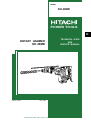
DH 40MR
POWER TOOLS
D
ROTARY HAMMER
DH 40MR
LIST No. E467
TECHNICAL DATA
AND
SERVICE MANUAL
Sep. 2002
SPECIFICATIONS AND PARTS ARE SUBJECT TO CHANGE FOR IMPROVEMENT
REMARK:
Throughout this TECHNICAL DATA AND SERVICE MANUAL, a symbol(s)
is(are) used in the place of company name(s) and model name(s) of our
competitor(s). The symbol(s) utilized here is(are) as follows:
Competitors
Symbols Utilized
Company Name
Model Name
B
BOSCH
GBH5-40DE
D
HILTI
TE55
C
MAKITA
HR4000C
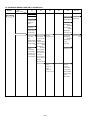
CONTENTS
Page
1. PRODUCT NAME ...........................................................................................................................1
2. MARKETING OBJECTIVE .............................................................................................................1
3. APPLICATIONS ..............................................................................................................................1
4. SELLING POINTS ..........................................................................................................................1
4-1. Selling Point Descriptions .............................................................................................................. 2
5. SPECIFICATIONS ..........................................................................................................................3
5-1. Specifications ................................................................................................................................. 3
5-2. Optional Accessories ..................................................................................................................... 4
6. COMPARISONS WITH SIMILAR PRODUCTS ..............................................................................8
6-1. Specification Comparisons ............................................................................................................ 8
6-2. Drilling Speed Comparisons .......................................................................................................... 9
6-3. Chiseling Performance Comparison ............................................................................................ 10
6-4. Comparison of Drilling Speed Change by Pushing Force ........................................................... 10
6-5. Drilling Speed and Quantity of Body Jumping .............................................................................. 11
7. PRECAUTIONS IN SALES PROMOTION ................................................................................... 11
7-1. Handling Instructions .................................................................................................................... 11
7-2. Caution Plate ............................................................................................................................... 12
8. REFERENCE INFORMATION ......................................................................................................12
8-1. Grease Replacement ................................................................................................................... 12
8-2. O-Ring Replacement ................................................................................................................... 12
8-3. Structure of DH 40MR Rotary Hammer ....................................................................................... 13
9. REPAIR GUIDE ............................................................................................................................18
9-1. Disassembly ................................................................................................................................ 18
9-2. Reassembly ................................................................................................................................. 20
9-3. Screw Locking Agent TB1401 ...................................................................................................... 23
9-4. Tightening Torque ........................................................................................................................ 23
9-5. Internal Wiring .............................................................................................................................. 24
9-6. Insulation Tests ............................................................................................................................ 25
9-7. No-load Current Value ................................................................................................................. 25
10. STANDARD REPAIR TIME (UNIT) SCHEDULES .....................................................................26
Assembly Diagram for DH 40MR
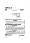
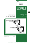
1. PRODUCT NAME
Hitachi Rotary Hammer, Model DH 40MR
2. MARKETING OBJECTIVE
The Model DH 40MR is an upgraded version of the current Models DH 40MA and DH 40MB, which feature the
use of SDS-max shank tools. The performance, durability and operability are greatly improved. With this
competitive Model DH 40MR, we aim to enhance the share of SDS-max type rotary hammers.
The main specifications are as follows:
(1) High drilling speed with low vibration and noise level
(2) Self-drilling (Good feeling)
(3) Internal double-insulation construction with sturdy aluminum frame
(4) Constant speed with variable speed control
(5) Soft-touch grip for easier handling
(6) Variabel lock mechanism for easy working-angle adjustment of chisels etc.
(7) A very original design
3. APPLICATIONS
Drilling holes in concrete and drilling anchor holes
Demolishing and chiseling of concrete. Edging, gravel road digging, compacting and tamping, grooving,
cutting, stripping and roughing, etc.
[Application examples]
Air conditioning
Piping and wiring
Electric fixtures
Sanitary facilities
Interior finishing
Other building, construction and repair work
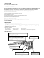
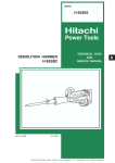
4. SELLING POINTS
High drilling speed with low vibration and noise level
Self-drilling (Good feeling)
A very original design
Change lever for switching between "Rotation +
Hammering" (for drilling), "Neutral" (for positioning
the tool tip) and "Hammering only" (for chiseling
and chipping)
Soft-touch grip handle
for easier handling
Soft-touch grip side-handle
for easier handling
Needle-pin type slip clutch
Internal double-insulation construction
with sturdy aluminum frame
--- 1 ---
Constant speed with
variable speed control
4-1. Selling Point Descriptions
4-1-1. High drilling speed with low vibration and noise level
The drilling speed is 10 % faster than that of similar products thanks to efficient striking energy transmission and
speed setting. Even so, the Model DH 40MR produces lower vibration and noise levels than those of similar
products.
Maker • Model
HITACHI
DH 40MR
HITACHI
DH 40MA/MB
B
D
C
Ratio of drilling speed
%
100
64
85
64
74
Full-load vibration level
dB (VL)
m/s2
116.8
118.0
119.8
116.1
118.5
6.9
7.9
9.8
6.4
8.4
Full-load noise level
dB (A)
92.4
94.6
93.7
93.2
93.5
No-load noise level
dB (A)
79.5
89.4
85.0
83.0
80.3
* Ratio of drilling speed: A 28-mm dia. drill bit is used.
Full-load vibration and noise levels: A 20-mm dia. drill bit is used.
4-1-2. Self-drilling (Good feeling)
Thanks to the computer-simulated optimum striking characteristics, the quantity of body jumping is less than that
of the current Model DH 40MA and the working tool smoothly penetrates into the workpiece with a light pressing
force. The Model DH 40MR realizes quicker self-drilling with better impact feeling.
Impact efficiency
About 10 % up
Maximum compressed air force (piston force)
About 50 % down
Quantity of body jumping
About 25 % down
4-1-3. Internal double-insulation construction with sturdy aluminum frame
The aluminum die-cast outer frame is very sturdy (same as the Models H 45MR/H 45SR). In addition, a plastic
internal S holder is adopted to realize double-insulation construction. Thus the housing has greater rigidity and
the double-insulated motor has greater durability. The Model DH 40MR is heavy-duty and the service life of the
carbon brush is greatly prolonged (1.5 times longer than the conventional one) minimizing disconnection of the
armature, deviation of the core and grease leakage.
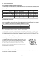
4-1-4. Dial type, constant speed with variable speed control
The Model DH 40MR is equipped with a built-in electronic control circuit
that can adjust the number of hammering steplessly between 1320 and
2650 min-1 with the dial. Even though the load varies, the Model
DH 40MR provides better operability and stable and efficient drilling
performance because the constant speed control minimizes changes in
Speed-adjust dial
number of rotation and hammering.
4-1-5. Soft-touch grip for easier handling
The double-layer molded handle consists of a nylon resin base covered with a soft plastic layer to ensure a soft
touch and firm, non-slip grip of the handles.
--- 2 ---
4-1-6. Change lever for switching between "Rotaion + Hammering", "Neutral" and "Hammering only"
The Model DH 40MR provides three functions, "rotation + hammering"
function (for drilling), "neutral" function (for positioning the tool tip) and
"hammering only" function (for chiseling and chipping).
These function modes can be easily switched by using the change lever.
The tool angle can be easily changed in 12 steps by turning the grip
with the change lever positioned at "Neutral".
4-1-7. Needle-pin type slip clutch
The Model DH 40MR is equipped with a needle-pin type slip clutch for higher slip torque accuracy and enhanced
safety (same as the Model DH 40MA).
5. SPECIFICATIONS
5-1. Specifications
Capacity
Drill bit (Max. diameter): 40 mm (1-9/16")
Core bit (Max. diameter): 105 mm (4-1/8")
Power source
AC single phase 50 Hz or 60 Hz
Voltage
110 V
120 V
220 V
230 V
240 V
Current
10 A
9.2 A
5A
4.8 A
4.6 A
Power input
950 W
Motor type
AC single-phase series commutator motor
Insulation structure
Double insulation
Enclosure
Materials: Aluminum alloy die casting
Nylon resin (Handle, handle cover, tail cover and crank cover)
Paint
: Silver green metallic, black
Switch
Trigger switch
Type of handles
D-shaped handle and side handle
Rotation rate
No load and full load: 240 to 480 min-1
Impact rate
No load and full load: 1,320 to 2,650 min-1
Weight
Product: 6.5 kg (14.3 lbs.); excluding cord and side handle
Packed: 10.0 kg (22.1 lbs.)
Packaging
Corrugated cardboard box with plastic tool case
Standard accessories
• Plastic case
• Side handle
• Hex. bar wrench (for M6)
• Hex. bar wrench (for M5)
• Hex. bar wrench (for M4)
• Stopper
• Grease (A)
1
1
1
1
1
1
1
• • • • • • • • • • • • • • • • • • • • • • • • • • • • • • • • • • • • • • • • • • • • • • • • • • • • • • • • • • • • • • • • • • • • • • • • • • • • • • • • • • • • • • • • • • • • • • • • •
• • • • • • • • • • • • • • • • • • • • • • • • • • • • • • • • • • • • • • • • • • • • • • • • • • • • • • • • • • • • • • • • • • • • • • • • • • • • • • • • • • • • • • • • • • • • • •
• • • • • • • • • • • • • • • • • • • • • • • • • • • • • • • • • • • • • • • • • • • • • • • • • • • • • • • • • • • • • • • • • • • • • • • • • • • • • •
• • • • • • • • • • • • • • • • • • • • • • • • • • • • • • • • • • • • • • • • • • • • • • • • • • • • • • • • • • • • • • • • • • • • • • • • • • • • • •
• • • • • • • • • • • • • • • • • • • • • • • • • • • • • • • • • • • • • • • • • • • • • • • • • • • • • • • • • • • • • • • • • • • • • • • • • • • • • •
• • • • • • • • • • • • • • • • • • • • • • • • • • • • • • • • • • • • • • • • • • • • • • • • • • • • • • • • • • • • • • • • • • • • • • • • • • • • • • • • • • • • • • • • • • • • • • • • • • • • • • •
• • • • • • • • • • • • • • • • • • • • • • • • • • • • • • • • • • • • • • • • • • • • • • • • • • • • • • • • • • • • • • • • • • • • • • • • • • • • • • • • • • • • • • • • • • • • • • • • • •
--- 3 ---
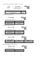
5-2. Optional Accessories
1. Drilling work for through-holes (Rotation + Hammering)
+
(1) Drill bit (SDS max shank)
Outer diameter
(mm)
16
19
22
25
28
32
38
40
(5/8")
(3/4")
(7/8")
(1")
(1-1/8")
(1-1/4")
(1-1/2")
(1-9/16")
Over length
(mm)
340
340
320
320
370
370
370
370
Code No.
Outer diameter
(mm)
313448
313449
313450
313451
313452
313453
313454
313455
(13-3/8")
(13-3/8")
(12-5/8")
(12-5/8")
(14-9/16")
(14-9/16")
(14-9/16")
(14-9/16")
16
19
22
25
28
32
38
40
(5/8")
(3/4")
(7/8")
(1")
(1-1/8")
(1-1/4")
(1-1/2")
(1-9/16")
Over length
(mm)
540
540
520
520
570
570
570
570
(21-1/4")
(21-1/4")
(20-15/32")
(20-15/32")
(22-7/16")
(22-7/16")
(22-7/16")
(22-7/16")
2. Drilling work for anchor holes (Rotation + Hammering)
1 Drill bit (Taper shank)
+
+
(1) Drill bit (taper shank)
(2) Taper shank adapter
(SDS max shank)
(3) Cotter
(1) Drill bit (Taper shank)
Outer diameter (mm)
11
12.3
12.7
14.3
14.5
17.5
(7/16")
(15/32")
(1/2")
(9/16")
(9/16")
(11/16")
(2) Taper shank adapter
(3) Cotter
Code No.
Taper dimension
Code No.
Code No.
944460
944461
993038
944462
944500
944463
Morse taper No. 1
313464
944477
2 SDS-plus shank bit adapter
+
+
(1) Drill bit (SDS-plus shank)
(2) SDS-plus shank
bit adapter
(SDS max shank)
Code No. 313465
--- 4 ---
Code No.
313456
313457
313458
313459
313460
313461
313462
313463
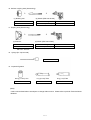
3. Boring work for large-diameter holes (Rotation + Hammering)
+
+
+
+
(1) Guide plate
(3) Core bit
(4) Core bit shank
(SDS max shank)
(2) Center pin
(1) Guide plate
Core bits with outer diameter of 32, 35, 38, 45, 50, 54, 60, 64, 70, 75, 79, 94, 100, 105 mm (1-1/4", 1-3/8",
1-1/2", 1-3/4", 2", 2-1/8", 2-3/8", 2-2/1", 2-3/4", 2-15/16", 3-1/8", 3-1/16", 3-15/16", 4-1/8")
[Guide plate is not used with core bits with outer diameter of 25 mm (1") and 29 mm (1-1/8")]
(2) Center pin
Code No. 956009 for core bits with outer diameter of 32, 35 mm (1-1/4", 1-3/8")
Code No. 955165 for core bits with outer diameter of 38, 45, 50, 54, 60, 64, 70, 75, 79, 94, 100, 105 mm
(1-1/2", 1-3/4", 2", 2-1/8", 2-3/8", 2-1/2", 2-3/4", 2-15/16", 3-1/8", 3-11/16", 3-15/16", 4-1/8")
[Center pin is not used with core bits with outer diameter of 25 mm (1") and 29 mm (1-1/8").]
(3) Core bit
Outer diameter (mm)
25
29
32
35
38
45
(1")
(1-1/8")
(1-1/4")
(1-3/8")
(1-1/2")
(1-3/4")
Code No. Outer diameter (mm)
955994
955995
955996
955998
956000
955154
50
54
60
64
70
75
Code No.
(2")
(2-1/8")
(2-3/8")
(2-1/2")
(2-3/4")
(2-15/16")
959706
955155
959707
956002
959708
959709
Outer diameter (mm)
79
94
100
105
(3-1/8")
(3-11/16")
(3-15/16")
(4-1/8")
Code No.
955157
956004
959710
955159
(4) Core bit shank (SDS max shank)
Code No. 313466 for core bits with outer diameter of 25, 29, 32, 35 mm (1", 1-1/8", 1-1/4", 1-3/8")
Code No. 313467 for core bits with outer diameter of 38, 45, 50, 54, 60, 64, 70, 75, 79, 94, 100, 105 mm
(1-1/2", 1-3/4", 2", 2-1/8", 2-3/8", 2-1/2", 2-3/4", 2-15/16", 3-1/8", 3-11/16", 3-15/16", 4-1/8")
4. Hole drilling .................................... For drilling steel and wood
+
(1) 13 mm drill chuck
(13VLA)
+
(2) Chuck adapter
(SDS max shank)
(3) Chuck wrench
(1) 13 mm drill chuck (13VLA)
(2) Chuck adapter
(3) Chuck wrench
Code No. 950272
Code No. 313468
Code No. 930515
--- 5 ---
5. Chemical anchor holes drilling work (Rotation + Hammering)
+
+
(1) Chemical anchor adapter
(SDS max shank)
(Socket)
Socket square size
Code No.
12.7 mm (1/2")
19.0 mm (3/4")
313469
313470
6. Demolition work (Hammering)
+
(1) Bull point (SDS max shank)
Overall length
Code No.
280 mm (11")
313471
400 mm (15-3/4")
313472
7. Grooving and edging (Hammering)
+
(1) Cold chisel (SDS max shank)
Overall length
Code No.
280 mm (11")
313473
400 mm (15-3/4")
313474
8. Cutting and stripping (Asphalt cutting etc.) (Hammering)
+
(1) Cutter (SDS max shank)
Overall length
Width
Code No.
400 mm (15-3/4")
50 mm (2")
313475
9. Digging (Substitute pick-ax) (Hammering)
+
(1) Scoop (SDS max shank)
Overall length
Code No.
400 mm (15-3/4")
313476
--- 6 ---
10. Surface roughing work (Hammering)
+
(1) Bushing tool
+
(2) Shank (SDS max shank)
Code No.
Overall length
Code No.
313477
220 mm (8-21/32")
313479
11. Tamping work (Hammering)
+
(1) Rammer
+
(2) Shank (SDS max shank)
Code No.
Overall length
Code No.
313478
220 mm (8-21/32")
313479
150 mm x 150 mm
12. Syringe (for chip removal)
Code No. 944575
13. Impact drill grease
500 g (1.1 lbs.) Can
Code No. 980927
70 g (2.5 oz) Tube
Code No. 308471
30 g (1 oz) Tube
Code No. 981840
(Note)
Code numbers listed above are subject to change without noitce. Please refer to periodic Technical News
Bulletins.
--- 7 ---
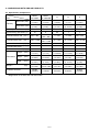
6. COMPARISONS WITH SIMILAR PRODUCTS
6-1. Specification Comparisons
Maker • Model
Hitachi
DH 40MR
Hitachi
DH 40MA/MB
B
D
C
Drill bit dia. (mm)
40
(1-9/16")
40
(1-9/16")
40
(1-9/16")
32
(1-1/4")
40
(1-9/16")
Core bit dia. (mm)
105
(4-1/8")
105
(4-1/8")
105
(4-1/8")
90
(3-17/32")
105
(4-1/8")
(W)
950
950
1,100
900
900
Impact energy per stroke (J)
10
8
8.5
7
7
Full-load rotation rate (min-1)
240 --- 480
360/
180 --- 360
0 --- 340
0 --- 480
230 --- 450
0 --- 3,300
0 --- 2,630
1,250 --- 2,500
Item
Capacity
Power input
Full-load impact rate
2,800/
(min-1) 1,320 --- 2,650
1,400 --- 2,800
Full-load vibration level (dB(VL))
116.8
118.0
119.8
116.1
118.5
Full-load noise level
(dB(A))
92.4
94.6
93.7
93.2
93.5
No-load noise level
(dB(A))
79.5
87.9
85.0
83.0
80.3
Length
(mm)
435
(17-1/8")
444
(17-1/2")
450
(17-23/32")
440
(17-11/32")
455
(17-15/16")
Dimensions Height
(mm)
255
(10-3/64")
252
(9-15/16")
255
(10-3/64")
230
(9-1/16")
250
(9-27/32")
(mm)
104
(4-7/64")
103
(4-1/16")
102
(4-1/64")
90
(3-17/32")
104
(4-1/8")
(kg)
6.5
(14.3 lbs.)
6.5/6.6
(14.3/14.6 lbs.)
6.2
(13.7 lbs.)
5.9
(13.0 lbs.)
6.2
(13.7 lbs.)
Double
insulation
Double
insulation
Double
insulation
Double
insulation
Double
insulation
Width
Weight *
Insulation structure
* Weight does not include cord and side handle.
--- 8 ---
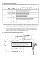
6-2. Drilling Speed Comparisons
Drilling speed varies considerably depending on the work conditions. Use the factory test results shown in Fig. 1
for comparison purposes only.
* Note that the data marked with asterisks are test results using drill bits which are beyond the tool's rated
capacity. Use the above data as a reference, for comparisons only.
Fig. 1
[Test conditions]
Direction
Pushing force
Test material
: Downward drilling
: 98 N (10 kgf)
: Concrete panel with a compression strength of 2,919 N/cm2 (240 kgf/cm2)
--- 9 ---
6-3. Chiseling Performance Comparison
Chiseling performance varies considerably depending on the work conditions. Use the factory test results shown
in Fig. 2 for comparison purposes only.
Fig. 2
(Note) B's chiseling amount is greater than the others because the circuit is controlled to make the number of
hammering in the "Hammering only" mode higher than that in the "Rotation + Hammering" mode.
However, B has inconveniences such as unbalanced hammering, heavy vibration, heavy tool shake,
and difficulty in positioning the tool because B increases only the number of hammering without
changing the weight of the striker (that is, hammering energy). The Model DH 40MR realizes selfchiseling in addition to self-drilling (4-1-2. Self-drilling (Good feeling)).
6-4. Comparison of Drilling Speed Change by Pushing Force
Drilling speed (mm/min.)
The graph shown in Fig. 3 illustrates the relationship between handle pushing force and drilling speed.
Pushing force
DH 40MR: Tool shake is not heavy in whole range. Good feeling.
DH 40MA/DH 40 MB: Tool shakes heavily at pushing force 50 N.
B: Tool shakes heavily at pushing force 50 N and 75 N.
D: Tool shake is not heavy in whole range, but the drilling
speed is slow and the feeling is not good.
Pushing force (N)
Fig. 3
--- 10 ---
Pushing force: 100 N
6-5. Drilling Speed and Quantity of Body Jumping
The graph shown in Fig. 4 illustrates the relationship between
drilling speed and quantity of body jumping. The quantity of
body jumping is less than the similar products and the working
tool quickly penetrates into the workpiece.
Ratio of
drilling speed
Ratio of quantity of
body jumping
Body jumping
is low !!
Tool shake is low.
Working tool quickly
penetrates into the
workpiece !!
Self drilling !!
Quantity of body jumping is
low and the tool smoothly
penetrates into the
workpiece with good feeling.
Fast
Fig. 4
--- 11 ---
7. PRECAUTIONS IN SALES PROMOTION
In the interest of promoting the safest and most efficient use of the Model DH 40MR Rotary Hammer by all of our
customers, it is very important that at the time of sale the salesperson carefully ensures that the buyer seriously
recognizes the importance of the contents of the Handling Instructions, and fully understands the meaning of the
precautions listed on the Caution Plate attached to each tool.
7-1. Handling Instructions
Although every effort is made in each step of design, manufacture and inspection to provide protection against
safety hazards, the dangers inherent in the use of any electric power tool cannot be completely eliminated.
Accordingly, general precautions and suggestions for the use of electric power tools, and specific precautions and
suggestions for the use of the Rotary Hammer are listed in the Handling Instructions to enhance the safe, efficient
use of the tool by the customer. Salespersons must be thoroughly familiar with the contents of the Handling
Instructions to be able to offer appropriate guidance to the customer during sales promotion.
7-2. Caution Plate
The Model DH 40MR unit is provided with a Caution Plate (illustrated below) which lists basic safety precautions
in use. Carefully ensure that the customer fully understands and follows these precautions before using tool.
For Australia and New Zealand
For the U.S.A. and Canada
--- 12 ---
8. REFERENCE INFORMATION
8-1. Grease Replacement
The striking portion and the speed reduction portion of the Model DH 40MR respectively use different types of
grease. It is not necessary to replenish the grease unless the tool is disassembled for repair or there is grease
leakage due to a damaged seal.
The striking portion uses special grease. To change the grease in the striking portion (inside the cylinder crank
case), carefully wipe the old grease off the parts, and re-lube with 50 g (1.8 oz) into the cylinder crank case
(connecting rod side). Take care not to overfill the grease as an excessive amount of grease can cause hammer
failure.
The speed reduction portion (inside the gear cover) uses Hitachi Motor Grease No. 29. The proper supply
volume is 30 g (1 oz). Never use the striking portion special grease in the speed reduction portion. Special
grease would leak into the motor portion and cause subsequent trouble.
Periodically replenish the inside of the slip clutch with Hitachi Motor Grease No. 29 to the full.
8-2. O-Ring Replacement
The O-rings (mounted on the striker and piston) are extremely important to ensure adequate sealing of the air
pressure. Although the O-rings are made of special rubber to give them a long service life, they do nonetheless
become worn, and should be replaced by new ones periodically depending on frequency of use of the tool. With
average use, it is recommended that the O-rings be replaced at least every six months to ensure maximum
effectiveness.
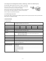
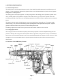
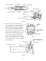
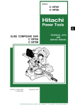
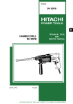
8-3. Structure of DH 40MR Rotary Hammer
Grip
Needle
holder
Second
hammer
Front cap
Retainer sleeve
Key rail
Needle pin
Needle roller
Air chamber Bevel gear
Crank shaft
Cylinder
Handle
Connecting rod
Clutch
Striker
First gear
Piston
O-ring
Second
gear
Bevel pinion
Armature
Control circuit ass'y
Fig. 5
--- 13 ---
Torque transmission
Armature revolution is transmitted to the second gear to rotate the bevel gear via the slip mechanism between
the second gear and bevel pinion axes. Rotation of the bevel gear is then transmitted to the cylinder keyed
thereto through the clutch. Cylinder rotation is conveyed to the retainer sleeve coupled together by means of
four needle pins and, then to the drill bit inserted into the retainer sleeve by way of three key rails and two
needle rollers which couple them together.
Striking operation
The rotation of the armature is transferred to the crank shaft and connecting rod, which in turn cause the
piston to reciprocate inside the cylinder. As the piston reciprocates, the changing air pressure inside the air
chamber between the piston and the striker causes the striker to continuously strike against the end of the
second hammer. At the same time, the air-cushion effect within the air chamber absorbs the impact of the
striker. Should the air escape from the air chamber, the air-cushion effect would cease, and the impact energy
would not be absorbed. Accordingly, the O-rings mounted on the striker and piston play an extremely
important role in sealing the air within the air chamber.
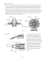
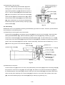
Mechanism to prevent idle hammering
The arrangement against idle hammering of this rotary hammer is about the same as for the DH 40MA in
which, when the drill bit or bull point is not longer pressed against the concrete or similar material, the second
hammer moves to a position shown in Fig. 6 so that the striker is displaced from its hammering position. This
opens the air hole so that piston movement causes no change in air pressure chamber, thus stopping the
hammering action.
Second hammer
Second hammer, striker movements distance
Fig. 6
--- 14 ---
Air chamber
Striker
Air hole
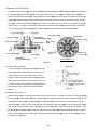
Slip clutch mechanism
The slip clutch mechanism is described below with reference to Fig. 7. The bevel pinion and the gear holder
are coupled together by the key and press-fitting. Spring (C) and needle pins are housed in elongated
grooves of the gear holder. The needle pin is pressed against the inner face of second gear by spring (C) to
allow idle rotation of the second gear relative to the gear holder. When an excess torque is exerted on the
bevel pinion shaft, the needle pin is raised upon the projection of the second gear against the load of spring
(C) to allow idle rotation of the second gear. With the arrangement, the clutch slips when an excessive torque
is applied to the working tool as when the drill bit contacts steel bar/wire in the concrete, protecting the
operator from unexpected motion of the side handle.
Bevel pinion
Gear holder
Needle pin
Spring (C)
Gear holder
Second gear
Bevel pinion
Key
Gear holder groove
Cross section A - A
Fig. 7
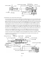
Tool holder
The tool inlet is covered with the front cap
(made of rubber) to prevent chips from
entering inside. Two needle rollers fall into
the round groove of the drill bit to retain the
Grip
working tool, and three key rails transmit the
Tool
rotation torque. To attach a working tool, align
the groove positions turning the working tool,
Needle roller (2 pieces)
then insert the working tool into the hole until
Forward
it contacts the innermost end of the hole.
Backward
Releasing the grip reverts the grip and
secures the tool in place. To remove the tool,
fully pull the grip backward and pull out the
Front cap
Grip
tool (Fig. 8).
Key rail (3 pieces)
Fig. 8
--- 15 ---
Handle and side handle
The handle section is of a two-layer structure. The base is made of glassfiber-reinforced plastic and the
outside layer is soft resin. They are molded in one piece.
The side handle also has a two-layer structure. The base is made of glassfiber-reinforced plastic base with a
steel nut and the outside layer is soft resin. They are molded in one piece. The newly designed handle and
side handle structure ensures more comfortable grip for improved operability.
Sealing and dust-proof structure
The cylinder crank case section is tightly sealed with three o-rings, three oil seals and rubber seal as shown in
Fig. 9. This prevents leakage of grease from the cases, while also protecting them against dust from outside.
The tool holder is also protected from foreign dust by means of a rubber front cap.
Rubber seal
O-ring
Front cap
O-ring
Oil seal
Oil seal
Fig. 9
--- 16 ---
Oil seal
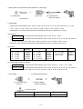
Switching between "Rotation + Hammering", "Neutral" and "Hammering only"
Lock sleeve
All the shanks of the SDS-max type working tools such as drill
Clutch
bits (for drilling) and bull points (for chiseling) have the same
Cylinder
shape. When chiseling or chipping with the Model DH 40MR,
it is necessary to stop the rotation and choose the
"Hammering only" mode by mean of the change lever to lock
the working tool against rotation.
Figure 10 is a cross-sectional view showing the "Rotation +
Hammering" mode, in which the bevel gear claw meshes with
the clutch claw to transmit rotation to the cylinder keyed to the
Bevel gear
clutch, so as to rotate the working tool.
Figure 11 is a cross-sectional view showing the "Neutral"
Change lever
Fig. 10
mode, in which, with the change lever turned 90˚, the bevel
gear is brought out of engagement with the clutch to cut off
Clutch
Lock sleeve
transmission of rotation. In this position, the tool holder grip
can be manually turned and the working tool (for chiseling or
Cylinder
chipping) is adjustable to the desired position in 12 steps
easily (Fig. 12).
Figure 13 is likewise a cross-sectional view showing the
"Hammering only" mode. With the change lever turned
another 90˚, the splines on the inner circumference of the lock
sleeve come into mesh with the splines on the outer
circumference of the clutch, so that the cylinder as well as the
Bevel gear
working tool are prevented from rotating.
Although the Model DH 40MR has three selectable modes as
Change lever
mentioned above, use of a working tool for chipping or
Fig. 11
chiseling in the "Rotation + Hammering" mode will result in an
accident. Be sure to instruct the customers to select the
Lock sleeve
Clutch
"Hammering only" mode when doing chiseling or chipping
work.
Cylinder
Grip
Fig. 12
Bevel gear
Change lever
Fig. 13
--- 17 ---
9. REPAIR GUIDE
The numbers in [Bold] correspond to the item numbers in the Parts List and exploded assembly diagrams.
9-1. Disassembly
(1) Disassembly of the tool holder
Pull the Grip [2] in the arrow direction to the full as
shown in Fig. 14. Remove the Front Cap [1]. (Front
Cap [1] is made of rubber and fitted securely. Pull
the Front Cap [1] forcefully to remove.) Thus the
Grip [2] can be removed from the Retainer Sleeve
Front Cap [1]
Grip [2]
[17].
Fig. 14
Stopper Ring [3]
Needle Roller [16]
Needle Holder [4]
Retainer Spring [5]
Spring Holder (A) [6]
Fig. 15
Remove the Stopper Ring [3] using a retaining ring puller. Then the Needle Holder [4], two Needle Rollers
D8 x 20 [16], Retainer Spring [5] and Spring Holder (A) [6] can be removed from the Retainer Sleeve [17]
(Fig. 15).
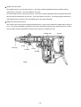
(2) Disassembly of the piston and the striker
Remove the Seal Lock Hex. Socket Hd. Bolt M4 x 12 [37] from the Crank Cover [39] then remove the Crank
Cover [39] from the Cylinder Crank Case [49]. Remove the Seal Lock Hex. Socket Hd. Bolt M6 x 45 [36] and
Seal Lock Hex. Socket Hd. Bolt M6 x 22 [89]. Remove the Gear Cover [66] from the Cylinder Crank Case
[49]. Remove the Bevel Pinion [50] (slip clutch) from the Cylinder Crank Case [49] (otherwise, Bevel Gear
[35] cannot be removed later). Remove the Seal Lock Hex. Socket Hd. Bolt M4 x 12 [37] from the Change
Lever [72] then remove the Change Lever [72]. Remove the Retaining Ring for D20 Hole [74] using a
retaining ring puller and remove the Lever Shaft [75] (otherwise, Bevel Gear [35] cannot be removed later).
Remove the Seal Lock Hex. Socket Hd. Bolt M6 x 25 [7] from the Front Cover [8]. Then the Retainer Sleeve
[17], Front Cover [8], Lock Sleeve [26], Lock Spring [25], Second Hammer [19], Clutch [31], Clutch Spring
[28], Cylinder [24], etc. can be removed from the Cylinder Crank Case [49] in an assembly state. Remove the
Bevel Gear [35] from the Cylinder Crank Case [49] by tapping the Front Cover [8] side with a plastic hammer.
Remove the Striker [29] from the Cylinder [24] by tapping with a plastic hammer. The Piston [32] remains in
the Cylinder Crank Case [49]. Remove the Retaining Ring for D10 Shaft [42] using a retaining ring puller and
remove the Connecting Rod [34] from the Crank Shaft [43] (Fig. 16).
--- 18 ---
Retainer Sleeve [17]
Lock Sleeve [26]
Clutch [31]
Cylinder [24]
Bevel Gear [35]
Piston [32]
Second Hammer [19]
Connecting
Rod [34]
Striker [29]
Cylinder Crank Case [49]
Crank Shaft [43]
Bevel Pinion [50]
Fig. 16
(3) Disassembly of the first gear and the crank shaft
Cylinder
Crank Case
[49]
Remove grease from the Connecting Rod [34] side and
the First Gear [64] side of the Cylinder Crank Case
[49]. Remove the Retaining Ring for D40 Hole [45]
from the Ball Bearing 6203DDCMPS2L [46] using a
Hole of Retaining
Ring for D40 Hole
[45]
retaining ring puller. At this time, shift the position of the
crank pin of the Crank Shaft [43] as shown in Fig. 17 so
that the hole of the retaining ring can be seen before
removal. Face the Connecting Rod [34] side of the
Crank Shaft [43]
Cylinder Crank Case [49] downward and place it on a
support. Press the end surface of the Crank Shaft [43]
Fig. 17
with a hand press to remove the First Gear [64] and the
Press the end surface of the
Crank Shaft [43] with a hand
press.
Crank Shaft [43] (Fig. 18).
Crank Shaft [43]
First Gear [64]
Cylinder Crank Case [49]
Support
Fig. 18
--- 19 ---
(4) Disassembly of the slip clutch
Press the end surface of
the Bevel Pinion with a
hand press.
Remove the Ball Bearing 629VVC2PS2L [61] with a
bearing puller. Place the assembly on a sleeve-type
support facing Washer (A) [55] downward as shown in
Bevel Pinion [50]
Fig. 19. Push the Spacer [60] side of the Bevel Pinion
Spacer [60]
[50] with a hand press to remove the Gear Holder [56]
and the Spacer [60] from the Bevel Pinion [50]. Before
removal of the Second Gear [59] from the Gear Holder
Washer (A) [55]
[56], put the assembly in a poly bag and disassemble it
inside the poly bag to prevent missing of Spring (C) [57]
Support
and the Needle [58].
Fig. 19
9-2. Reassembly
Reassembly can be accomplished by following the disassembly procedure in reverse. However, special attention
should be given to the following items.
(1) Reassembly of the first gear and the crank shaft
Press-fit Oil Seal (B) [48] into the Cylinder Crank Case [49] and mount O-ring (S-40) [47]. Press-fit the Ball
Bearing 6203DDCMPS2L [46]. Mount the Retaining Ring for D40 Hole [45] using a retaining ring puller.
Press-fit the Crank Shaft [43] into the Ball Bearing 6203DDCMPS2L [46]. Put the Feather Key 3 x 3 x 8 [44]
in the groove of the Crank Shaft [43] and press-fit the First Gear [64] with a suitable tool while holding the flat
portion of the Crank Shaft [43] with a steel bar. Before press-fitting, make sure that the Feather Key 3 x 3 x 8
[44] fits in the key groove of the First Gear [64] (Fig. 20).
First Gear [64]
Cylinder Crank Case [49]
Suitable tool
Feather Key 3 x 3 x 8 [44]
Oil Seal (B) [48]
O-ring (S-40) [47]
Ball Bearing
6203DDCMPS2L [46]
Retaining Ring for
D40 Hole [45]
Steel bar
Crank Shaft [43]
Fig. 20
(2) Reassembly of the piston
Insert the Piston Pin [33] into the 8-mm dia. hole (marked side) of the Piston [32] and the Connecting Rod [34]
then press-fit it. Mount the O-ring [30] to the Piston [32]. Be careful not to protrude the Piston Pin [33] from
the outside diameter of the Piston [32]. Move the crank pin of the Crank Shaft [43] to the bottom dead center
and mount the piston assembly to the Crank Shaft [43] from the front cover side of the Cylinder Crank Case
[49]. Mount the Retaining Ring for D10 Shaft [42] using a retaining ring puller (Fig. 21).
--- 20 ---
Cylinder Crank Case [49]
Piston Pin [33]
Retaining Ring
for D10 Shaft [42]
Mark
Crank Pin
Crank Shaft [43]
Connecting Rod [34]
O-ring [30]
Piston [32]
Fig. 21
(3) Reassembly of the cylinder and the retainer sleeve
Press-fit the Retainer Sleeve [17] into the Ball Bearing 6007DDUAV2S [14]. Secure it with the Retaining Ring
for D35 Shaft [13]. Mount the Second Hammer [19], Damper Washer [20], Damper [21] and Damper Holder
[22] to the Retainer Sleeve [17]. Mount the Damper Washer [20] aligning the R surface of the inside diameter
with the R surface of the Second Hammer [19]. Insert the Striker [29] into the Cylinder [24] then insert the
Cylinder [24] into the Retainer Sleeve [17]. Secure the Cylinder [24] and the Retainer Sleeve [17] with the
four Needle Pins D6 x 6 [23] and cover it with Spring Holder (B) [27]. Mount the Bearing Washer [15], Lock
Spring [25], Lock Sleeve [26], Clutch Spring [28], Clutch [31] and Bevel Gear [35] to the Cylinder [24]. Mesh
the claw of the Lock Sleeve [26] with the claw of the Clutch [31]. Insert the retainer sleeve assembly into the
Cylinder Crank Case [49] aligning the spline of the Lock Sleeve [26] with the spline groove at the inner
circumference of the Cylinder Crank Case [49]. If the slip clutch assembly and the Lever Shaft [75] are
mounted in the Cylinder Crank Case [49] first, the Bevel Gear [35] will be an obstacle to reassembly. Before
mounting the slip clutch assembly and the Lever Shaft [75], mount the retainer sleeve assembly to the
Cylinder Crank Case [49] (Fig. 22).
Retainer Sleeve [17]
Damper
Washer [20]
Lock Spring [25]
Striker [29]
Second Hammer [19]
Lock Sleeve [26]
Clutch [31]
Bevel Gear [35]
Cylinder [24]
Retaining Ring
for D35 Shaft [13]
Ball Bearing
6007DDUAV2S [14]
Bearing
Washer [15]
Cylinder Crank Case [49]
Clutch
Spring [28]
Damper [21]
Damper Holder [22]
Needle Pin D6 x 6 [23]
Spring Holder (B) [27]
Fig. 22
--- 21 ---
(4) Reassembly of the slip clutch
Press-fit the Bevel Pinion [50] into the Collar [51] and the Ball Bearing 6002DDCMPS2L [53] then insert it into
the Washer [54] and Washer (A) [55]. Mount the Feather Key 3 x 3 x 8 [44] to the Bevel Pinion [50] then
press-fit into the Gear Holder [56]. Mount the Second Gear [59] around the outer circumference of the Gear
Holder [56]. Before mounting, apply Hitachi Motor Grease No. 29 to the inner circumference of the Second
Gear [59]. Insert the ten Needles [58] being careful not to incline them, then push in ten Springs (C) [57] as
shown in Fig. 23. Fill the slots and the through holes of the Gear Holder [56] with Hitachi Motor Grease No.
29. Press-fit the Bevel Pinion [50] into the Spacer [60] and the Ball Bearing 629VVC2PS2L [61].
Bevel Pinion [50]
Washer (A) [55]
Gear Holder [56]
Second Gear [59]
Collar [51]
Gear Holder [56]
Ball Bearing
6002DDCMPS2L [53]
Needle [58]
Spring (C) [57]
Bevel Pinion
[50]
Washer [54]
Slot of gear
holder
Spacer [60]
Ball Bearing
629VVC2PS2L [61]
Feather Key
3 x 3 x 8 [44]
Cross section A - A
Fig. 23
(5) Carbon brush inspection
Wear limit
The motor employs Carbon Brushes [91] which are
consumable parts. When they become worn to or
73
near "wear limit" (7 mm), it could result in motor
trouble. Replace the Carbon Brushes [91] with new
7 mm
ones which are numbered "73" as shown in Fig. 24.
17 mm
In addition, always keep Carbon Brushes [91] clean
and ensure that they slide freely within the brush
No. of carbon brush
("73" means the last
two digits of the code
number.)
Fig. 24
holders.
(6) Application of lubricant
Apply special grease (for hammer and rotary hammer) to the inner circumference of the Connecting Rod [34],
the O-rings [30] of the Striker [29] and the Piston [32], the sliding portion of the Second Hammer [19], the Oil
Seal [10], Oil Seal (A) [52], Oil Seal (B) [48], the Damper [21] and inner and outer circumferences of the
Bevel Gear [35]. Fill 50 g of the special grease in the Cylinder Crank Case [49] on the Connecting Rod [34]
side and 20 g in the Cylinder Crank Case [49] on the Clutch [31] side. Apply Hitachi Motor Grease No. 29 to
the Needle Bearing (M661) [65], the pinion portion of the Armature [82] and the Needle Roller D8 x 20 [16].
Fill 30 g of the Hitachi Motor Grease No. 29 in the Cylinder Crank Case [49] on the First Gear [64] side and
the Gear Cover [66] side.
--- 22 ---
(7) Oil seal and others
Take care not to scratch or cut Oil Seal (A) [52] and Oil Seal (B) [48] of the Cylinder Crank Case [49], Oil Seal
[10] and O-ring (1AS-60) [9] of the Front Cover [8], O-ring (C) [18] of the Second Hammer [19], Rubber Seal
[41] of the Crank Cover [39] and the O-ring [30] of the Piston [32] and the Striker [29].
9-3. Screw Locking Agent TB1401
Apply screw locking agent TB1401 to all hex. socket head bolts M4, M5 and M6.
(Note) Be sure to apply screw locking agent ThreeBond TB1401 to the threads during reassembly, as the bolts
loosened with vibration may cause damage to the tool body.
9-4. Tightening Torque
Front cover mounting bolts ............................................................................... 13.7 +0.98
N• m (140
0
+10
0
kgf• cm)
(Hex. socket head bolt M6 x 25)
Tapping screw D5............................................................................................. 2.94
0.49 N• m (30
Hex. socket head bolt M6 x 45 ......................................................................... 9.8 +1.96
N• m (100
0
+20
0
5 kgf• cm)
kgf• cm)
Hex. socket head bolt M6 x 22
Tail cover mounting bolt ................................................................................... 4.41
0.49 N• m (45
5 kgf• cm)
0.49 N• m (45
5 kgf• cm)
Tapping screw (W/Flange) D4 .......................................................................... 1.96
0.49 N•m (20
5 kgf•cm)
Handle mounting bolt ....................................................................................... 4.41
0.49 N•m (45
5 kgf•cm)
(Hex. socket head bolt M5 x 10)
Crank cover mounting bolt ............................................................................... 4.41
Lever shaft mounting bolt
(Hex. socket head bolt M4 x 12)
(Hex. socket head bolt (W/Flange) M5x14)
--- 23 ---
9-5. Internal Wiring
Wiring diagram for products without noise suppressor
Switch
Stator
Controller
circuit ass'y
Armature
Plug
Connector
Wiring diagram for products with noise suppressor
Switch
Stator
Armature
Controller circuit
ass'y (include
noise suppressor)
Plug
Pillar terminal
Mounting diagram for products with noise suppressor
Case (B)
Control circuit ass'y
(include noise suppressor)
Housing
Lead wires of switch and
cord
Tab
Lead wire of stator
Lead wire of noise
suppressor
Tail cover
Fig. 25
--- 24 ---
9-6. Insulation Tests
On completion of disassembly and repair, measure the insulation resistance and dielectric strength.
Insulation resistance: 7 MΩ or more with DC 500 V Megohm Tester
Dielectric strength:
AC 4,000 V/1 minute, with no abnormalities .................. 220 V --- 240 V
(and 110 V for U.K. products)
AC 2,500 V/1 minute, with no abnormalities ................... 110 V --- 127 V
(except U.K. products)
9-7. No-load Current Value
After no-load operation for 30 minutes, the no-load current value should be as follows:
Voltage (V)
110
120
220
230
240
Current (A) (Max.)
6.4
5.9
3.2
3.1
2.9
--- 25 ---
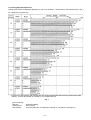
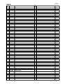
10. STANDARD REPAIR TIME (UNIT) SCHEDULES
MODEL
Variable
Fixed
10
20
30
40
50
60 min.
Work Flow
DH 40MR
Housing Ass'y
Gear Cover
Stator Ass'y
Needle Bearing
Handle Cover
Switch (C)
Cord
Armature
Ball Bearing
(6201DD)
Ball Bearing
(608VV)
Washer (A)
Tail Cover
Crank Cover
Rubber Seal
Dust Washer (B)
General Assembly
Handle
Front Cap
Grip
Needle Holder
Front Cover
Controller Circuit
O-ring (1AS-60)
Oil Seal
Retainer Spring Urethane Ring
Spring Holder Urethane Ring
Holder
(A)
Ball Bearing
(6007DD)
O-ring
Lever Shaft
Lever Holder
Change Lever
Lever Spring
Bearing Washer
Pushing Button
Second Hammer
Crank Shaft
Cylinder Crank
Case
Ball Bearing
(6203DD)
Oil Seal (B)
O-ring
First Gear
Slip Clutch Ass'y
Needle Roller
Retainer Sleeve
O-ring (C)
Damper Washer
Damper
Damper Holder
Striker
O-ring x 2
Piston
Piston Pin
Connecting Rod
--- 26 ---
Needle
Cylinder
Lock Spring
Lock Sleeve
Spring Holder
Clutch Spring
Clutch
Bevel Gear
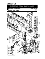
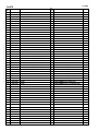
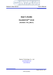
LIST NO. E467
ELECTRIC TOOL PARTS LIST
ROTARY HAMMER
Model DH 40MR
2002 • 9 • 30
(E1)
37
38
1
2
39
3
40
4
12
13
5
14
15
6
7
16
50
41
44
42
51
52
8
17
23
43
9
53
10
24
11
18
25
19
62
55
45
20
26
54
44
21
56
46
22
36
57
47
27
58
48
28
49
59
29
60
30
31
30
61
32
63
33
34
80
35
81
64
82
65
83
66
70
69
76
75
102
84
74
73
68
96
103
72
104
37
85
71
67
105
106
86
87
88
77
97
98
78
79
99 107
501
89
101
91
503
109
110
92
502
108
100
114
111
115
90
116
93
504
112
94
505
95
113
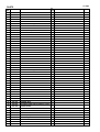
PARTS
ITEM
NO.
1
DH 40MR
CODE NO.
NO.
USED
DESCRIPTION
321-306
FRONT CAP
1
2
321-305
GRIP
1
3
318-590
STOPPER RING
1
4
321-304
NEEDLE HOLDER
1
5
321-303
RETAINER SPRING
1
6
321-302
SPRING HOLDER (A)
1
7
981-942
SEAL LOCK HEX. SOCKET HD. BOLT M6X25
4
8
321-300
FRONT COVER
1
9
956-996
O-RING (1AS-60)
1
10
321-301
OIL SEAL
1
11
981-859
URETHANE RING
1
12
315-868
URETHANE RING HOLDER
1
13
948-131
RETAINING RING FOR D35 SHAFT
1
14
600-7DD
BALL BEARING 6007DDUAV2S
1
15
321-297
BEARING WASHER
1
16
313-421
NEEDLE ROLLER D8X20
2
17
321-286
RETAINER SLEEVE
1
18
313-396
O-RING (C)
1
19
321-287
SECOND HAMMER
1
20
321-288
DAMPER WASHER
1
21
321-289
DAMPER
1
22
321-290
DAMPER HOLDER
1
23
313-057
NEEDLE PIN D6X6
4
24
321-291
CYLINDER
1
25
321-298
LOCK SPRING
1
26
321-299
LOCK SLEEVE
1
27
321-293
SPRING HOLDER (B)
1
28
321-294
CLUTCH SPRING
1
29
321-292
STRIKER
1
30
986-104
O-RING
2
31
321-295
CLUTCH
1
32
321-284
PISTON
1
33
980-708
PISTON PIN
1
34
321-285
CONNECTING ROD
1
35
321-296
BEVEL GEAR
1
36
986-940
SEAL LOCK HEX. SOCKET HD. BOLT M6X45
4
37
983-162
SEAL LOCK HEX. SOCKET HD. BOLT M4X12
5
HITACHI LABEL
1
CRANK COVER
1
HITACHI LABEL
1
38
39
321-315
40
41
321-314
RUBBER SEAL
1
42
939-540
RETAINING RING FOR D10 SHAFT (10 PCS.)
1
43
321-275
CRANK SHAFT
1
44
944-109
FEATHER KEY 3X3X8
2
45
948-391
RETAINING RING FOR D40 HOLE
1
46
620-3DD
BALL BEARING 6203DDCMPS2L
1
47
996-363
O-RING (S-40)
1
48
321-274
OIL SEAL (B)
1
49
321-273
CYLINDER CRANK CASE
1
50
321-278
BEVEL PINION
1
51
321-279
COLLAR
1
--- 2 ---
* ALTERNATIVE PARTS
REMARKS
9 -- 02
PARTS
ITEM
NO.
52
DH 40MR
CODE NO.
NO.
USED
DESCRIPTION
313-050
OIL SEAL (A)
1
53
600-2DD
BALL BEARING 6002DDCMPS2L
1
54
313-058
WASHER
1
55
313-053
WASHER (A)
1
REMARKS
56
321-281
GEAR HOLDER
57
321-282
SPRING (C)
10
1
58
320-343
NEEDLE
10
59
321-280
SECOND GEAR
1
60
321-283
SPACER
1
61
629-VVM
BALL BEARING 629VVC2PS2L
1
62
321-277
SLIP CLUTCH ASS’Y
1 INCLUD.44,50,51,53-61
63
944-525
BEARING WASHER (C)
1
64
321-276
FIRST GEAR
1
65
939-299
NEEDLE BEARING (M661)
1
66
321-319
GEAR COVER
1
67
313-078
SIDE HANDLE
1
68
313-079
HANDLE HOLDER
1
69
313-080
HANDLE BOLT
1
70
971-786
STOPPER ROD
1
LEVER LABEL
1
71
72
321-309
CHANGE LEVER
1
73
321-308
LEVER HOLDER
1
74
311-229
RETAINING RING FOR D20 HOLE
1
75
321-307
LEVER SHAFT
1
76
873-095
O-RING (P-16)
1
77
321-310
LEVER SPRING
1
78
321-311
PUSHING BUTTON
1
79
321-312
PIN D2X10
1
80
620-1DD
BALL BEARING 6201DDCMPS2L
1
81
302-429
DUST WASHER (B)
1
*
82
360-591U
ARMATURE ASS’Y 110V-120V
1 INCLUD.80,81,86,87
*
82
360-591E
ARMATURE 220V-230V
1
*
82
360-591F
ARMATURE 240V
1
83
321-320
FAN GUIDE
1
84
953-174
HEX. HD. TAPPING SCREW D5X55
2
*
85
340-542C
STATOR ASS’Y 110V
1 INCLUD.96
*
85
340-542G
STATOR ASS’Y 120V
1 INCLUD.96
*
85
340-542E
STATOR ASS’Y 220V-230V
1 INCLUD.96
*
85
340-542H
STATOR ASS’Y 220V
1 INCLUD.96 FOR HKG
*
85
340-542F
STATOR ASS’Y 240V
1 INCLUD.96
*
*
86
982-631
WASHER (A)
1
87
608-VVM
BALL BEARING 608VVC2PS2L
1
88
318-721
MAGNET
1
89
321-313
SEAL LOCK HEX. SOCKET HD. BOLT M6X22
2
90
935-829
BRUSH CAP
2
91
999-073
CARBON BRUSH (AUTO STOP TYPE) (1 PAIR)
2
91
999-043
CARBON BRUSH (1 PAIR)
2 FOR HKG
92
971-001
BRUSH HOLDER
2
93
938-477
HEX. SOCKET SET SCREW M5X8
2
94
321-321
TAIL COVER
1
95
877-839
SEAL LOCK HEX. SOCKET HD. BOLT M5X10
2
9 -- 02
* ALTERNATIVE PARTS
--- 3 ---
PARTS
ITEM
NO.
96
DH 40MR
CODE NO.
NO.
USED
DESCRIPTION
930-703
BRUSH TERMINAL
2
97
321-322
VINYL TUBE
1
98
321-318
HOUSING ASS’Y
1
99
321-317
CASE (B)
1
*
100
321-326
CONTROLLER CIRCUIT 110V
1
*
100
321-328
CONTROLLER CIRCUIT 120V
1
*
100
321-327
CONTROLLER CIRCUIT 220V-240V
1
*
101
317-113
INTERNAL WIRE
1
102
321-323
HANDLE
1
103
998-485
HEX. SOCKET HD. BOLT (W/FLANGE) M5X14
6
104
313-093
SWITCH (C) (2P SCREW TYPE W/O LOCK)
1
105
321-324
HANDLE COVER
1
106
301-653
TAPPING SCREW (W/FLANGE) D4X20 (BLACK)
2
SDS MAX LABEL
1
107
REMARKS
INCLUD.92,93
EXCEPT FOR HKG,USA,CAN
*
108
NAME PLATE
1
*
109
980-063
TERMINAL
1
*
109
930-804
TERMINAL M4.0 (10 PCS.)
1
FOR USA,CAN
*
110
981-373
TUBE (D)
2
FOR CORD
*
111
958-049
CORD ARMOR D8.2
1
*
111
940-778
CORD ARMOR D10.7
1
*
112
959-141
CONNECTOR 50092 (10 PCS.)
1
FOR HKG
*
113
938-307
PILLAR TERMINAL
1
EXCEPT FOR HKG
*
114
960-266
CORD CLIP
1
*
114
981-987Z
CORD CLIP
1
115
984-750
TAPPING SCREW (W/FLANGE) D4X16
2
*
116
500-390Z
CORD
1
(CORD ARMOR D10.7)
*
116
500-446Z
CORD
1
(CORD ARMOR D10.7) FOR GBR (230V)
*
116
500-454Z
CORD
1
(CORD ARMOR D10.7) FOR GBR (110V)
*
116
500-435Z
CORD
1
(CORD ARMOR D8.2) FOR HKG
*
116
500-391Z
CORD
1
(CORD ARMOR D10.7) FOR SUI
*
116
500-408Z
CORD
1
(CORD ARMOR D8.2) FOR NZL
*
116
500-439Z
CORD
1
(CORD ARMOR D8.2) FOR AUS
*
116
500-434Z
CORD
1
(CORD ARMOR D10.7) FOR USA,CAN
--- 4 ---
FOR SUI
* ALTERNATIVE PARTS
9 -- 02
DH 40MR
STANDARD ACCESSORIES
ITEM
NO.
501
CODE NO.
321-325
NO.
USED
DESCRIPTION
CASE
1
502
981-840
GREASE (A) FOR HAMMER.HAMMER DRILL (30G)
1
503
943-277
HEX. BAR WRENCH 3MM
1
504
944-458
HEX. BAR WRENCH 4MM
1
505
944-459
HEX. BAR WRENCH 5MM
1
REMARKS
OPTIONAL ACCESSORIES
ITEM
NO.
601
CODE NO.
NO.
USED
DESCRIPTION
313-448
DRILL BIT (SDS MAX) D16X340
1
602
313-456
DRILL BIT (SDS MAX) D16X540
1
603
313-449
DRILL BIT (SDS MAX) D19X340
1
604
313-457
DRILL BIT (SDS MAX) D19X540
1
605
313-450
DRILL BIT (SDS MAX) D22X320
1
606
313-458
DRILL BIT (SDS MAX) D22X520
1
607
313-451
DRILL BIT (SDS MAX) D25X320
1
608
313-459
DRILL BIT (SDS MAX) D25X520
1
609
313-452
DRILL BIT (SDS MAX) D28X370
1
610
313-460
DRILL BIT (SDS MAX) D28X570
1
611
313-453
DRILL BIT (SDS MAX) D32X370
1
612
313-461
DRILL BIT (SDS MAX) D32X570
1
613
313-454
DRILL BIT (SDS MAX) D38X370
1
614
313-462
DRILL BIT (SDS MAX) D38X570
1
615
313-455
DRILL BIT (SDS MAX) D40X370
1
616
313-463
DRILL BIT (SDS MAX) D40X570
1
617
944-460
TAPER SHANK DRILL BIT D11X100
1
618
944-461
TAPER SHANK DRILL BIT D12.3X110
1
619
993-038
TAPER SHANK DRILL BIT D12.7X110
1
620
944-462
TAPER SHANK DRILL BIT D14.3X110
1
621
944-500
TAPER SHANK DRILL BIT D14.5X110
1
622
944-463
TAPER SHANK DRILL BIT D17.5X120
1
623
313-464
TAPER SHANK ADAPTER ASS’Y (SDS MAX) NO.1
1
624
944-477
COTTER
1
625
313-465
ADAPTER (SDS MAX) FOR SDS PLUS SHANK BIT
1
626
955-994
CORE BIT 25MM
1
627
955-995
CORE BIT 29MM
1
628
955-996
CORE BIT 32MM
1
629
955-997
GUIDE PLATE (FOR CORE BIT 32MM)
1
630
955-998
CORE BIT 35MM
1
631
955-999
GUIDE PLATE (FOR CORE BIT 35MM)
1
9 -- 02
* ALTERNATIVE PARTS
REMARKS
INCLUD.624
INCLUD.629
INCLUD.631
--- 5 ---
DH 40MR
OPTIONAL ACCESSORIES
ITEM
NO.
632
CODE NO.
NO.
USED
DESCRIPTION
956-000
CORE BIT 38MM
1
633
956-001
GUIDE PLATE (FOR CORE BIT 38MM)
1
634
955-154
CORE BIT 45MM
1
635
955-166
GUIDE PLATE (FOR CORE BIT 45MM)
1
636
955-155
CORE BIT 54MM
1
637
955-167
GUIDE PLATE (FOR CORE BIT 54MM)
1
638
956-002
CORE BIT 64MM
1
639
956-003
GUIDE PLATE (FOR CORE BIT 64MM)
1
640
955-157
CORE BIT 79MM
1
641
955-168
GUIDE PLATE (FOR CORE BIT 79MM)
1
642
956-004
CORE BIT 94MM
1
643
956-005
GUIDE PLATE (FOR CORE BIT 94MM)
1
644
955-159
CORE BIT 105MM
1
645
955-169
GUIDE PLATE (FOR CORE BIT 105MM)
1
646
956-009
CENTER PIN (B) 147L FOR CORE BIT D32-35
1
647
955-165
CENTER PIN (A) 133L FOR CORE BIT D38-150
1
648
313-466
CORE BIT SHANK (B) SDS MAX D25-35
1
649
313-467
CORE BIT SHANK (A) SDS MAX D38-150
1
650
950-272
DRILL CHUCK 13VLA
1
651
930-515
CHUCK WRENCH 10G
1
652
313-468
CHUCK ADAPTER (SDS MAX)
1
653
313-469
CHEMICAL ANCHOR ADAPTER (SDS MAX) 12.7MM
1
654
313-470
CHEMICAL ANCHOR ADAPTER (SDS MAX)19MM
1
655
313-471
BULL POINT (SDS MAX) 280L
1
656
313-472
BULL POINT (SDS MAX) 400L
1
657
313-473
COLD CHISEL (SDS MAX) 280MM
1
658
313-474
COLD CHISEL (SDS MAX) 400MM
1
659
313-475
CUTTER (SDS MAX) W50X400L
1
660
313-476
SCOOP (SDS MAX) 400L
1
661
313-478
RAMMER (SDS MAX) 150MM X 150MM
1
662
313-477
BUSHING TOOL (SDS MAX)
1
663
313-479
SHANK (SDS MAX)FOR RAMMER,BUSHING TOOL
1
664
320-859
SYRINGE (BLOW-OUT BULB TYPE)
1
665
318-085
SYRINGE (BELLOWS TYPE)
1
666
308-471
GREASE FOR HAMMER.HAMMER DRILL (70G)
1
667
980-927
GREASE FOR HAMMER.HAMMER DRILL (500G)
1
--- 6 ---
* ALTERNATIVE PARTS
REMARKS
INCLUD.633
INCLUD.635
INCLUD.637
INCLUD.639
INCLUD.641
INCLUD.643
INCLUD.645
INCLUD.651
Printed in Japan
(020930N)
9 -- 02