1
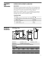
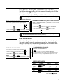
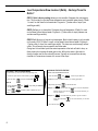
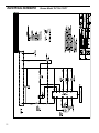
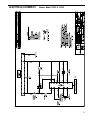
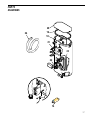
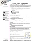
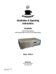
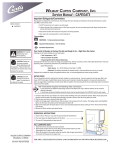
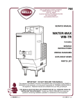
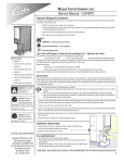
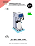
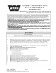
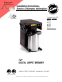
FIND OUT MORE
ON THE WEB.
WILBURCURTIS.COM
Installation Instructions,
Service & Warranty Information
Revised: Aug 2003
MODELS INCLUDED
• TLP10
• TLP15
• TLP20
• TLP30*
• TLP61
* 30 is Not UL Listed
TLP
DRAFT
COPY
DIGITAL
AIRPOT
BREWER
Not Released. This Version Exists as File No.
I:\DIAGRAMS\FRANK\FX-134.p65
C
UL
®
UL
®
WILBUR CURTIS COMPANY • Montebello, CA 90640
ISO 9001 REGISTERED
FOR THE LATEST SPEC INFORMATION GO TO WWW.WILBURCURTIS.COM
TABLE
OF
CONTENTS
IMPOR
IMPORTTANT
SAFEGUARDS/
CONVENTIONS
Important Safeguards / Conventions . . . . . . . . . . . . . . . . . . . . . . . . 2
Contents & Unpacking . . . . . . . . . . . . . . . . . . . . . . . . . . . . . . . . . . . 3
Rough-in Drawing . . . . . . . . . . . . . . . . . . . . . . . . . . . . . . . . . . . . . . 3
Quick Start & Setup . . . . . . . . . . . . . . . . . . . . . . . . . . . . . . . . . . . . 4
Brewing Instructions . . . . . . . . . . . . . . . . . . . . . . . . . . . . . . . . . . . . 5
Programming . . . . . . . . . . . . . . . . . . . . . . . . . . . . . . . . . . . . . . . . . 6
Brew Temperature . . . . . . . . . . . . . . . . . . . . . . . . . . . . . . . . . . .6
Brew Volume . . . . . . . . . . . . . . . . . . . . . . . . . . . . . . . . . . . . . . . 7
Brew Cycle Counter . . . . . . . . . . . . . . . . . . . . . . . . . . . . . . . . . 7
Low Temperature Brew “Delta” Lockout . . . . . . . . . . . . . . . . . .8.
Trouble Shooting . . . . . . . . . . . . . . . . . . . . . . . . . . . . . . . . . . . . . . . 9
High Temp Reset Thermostat . . . . . . . . . . . . . . . . . . . . . . . . . . . . . 10
Care & Maintenance . . . . . . . . . . . . . . . . . . . . . . . . . . . . . . . . . . . .10
Electrical Schematics
TLP10/12 . . . . . . . . . . . . . . . . . . . . . . . . . . . . . . . . . . . . . . . . .11
TLP15/17 . . . . . . . . . . . . . . . . . . . . . . . . . . . . . . . . . . . . . . . . .12
TLP20/22 . . . . . . . . . . . . . . . . . . . . . . . . . . . . . . . . . . . . . . . . .13
TLP30/32 . . . . . . . . . . . . . . . . . . . . . . . . . . . . . . . . . . . . . . . . .14
TLP61/63 . . . . . . . . . . . . . . . . . . . . . . . . . . . . . . . . . . . . . . . . .15
Illustrated Parts Diagram . . . . . . . . . . . . . . . . . . . . . . . . . . . . 16 – 17
Illustrated Parts List . . . . . . . . . . . . . . . . . . . . . . . . . . . . . . . . . . . . 18
Warranty . . . . . . . . . . . . . . . . . . . . . . . . . . . . . . . . . . . . . . . . . . . . 19
This appliance is designed for commercial use. Any servicing other than cleaning and
maintenance should be performed by an authorized Wilbur Curtis service center.
• Do NOT immerse the unit in water or any other liquid
• To reduce the risk of fire or electric shock, do NOT open top or side panel.
There are no user serviceable parts located inside.
Repair should be done only by authorized service personnel.
• Keep hands and other items away from hot parts of the appliance during
operation.
• Never clean with scouring powders or harsh implements (see Care &
Maintenance, page 10).
CONVENTIONS
WARNINGS - TO HELP A VOID PERSONAL INJUR
INJURYY
IMPOR
ACTOR
IMPORTTANT NOTES/CAUTIONS - FROM THE FFACTOR
ACTORYY
SANIT
ATION REQUIREMENTS
SANITA
2
CONTENTS
AND
UNPACKING
SHIPPING CARTON CONTENTS & UNPACKING
UNPACKING
All products manufactured by the Wilbur Curtis Company are
thoroughly inspected at the factory and are warranted to be
free of all defects and faulty workmanship. These brewers are
packaged for maximum protection during shipping.
Make sure the shipping carton is not damaged or punctured.
Unpack the carton, carefully inspecting the contents for any
damage that may have occurred in transit.
STANDARD ITEMS
Qty Item
Part Nº
1 Coffee Brewer, ThermoLogic Low Profile TLP
1
1
25
1
ROUGH-IN
DRAWINGS
Brew Cone
Elbow, ¼ x 3?8 Flare
WC-3621
WC-2401
Paper Filters
Service Manual, TLP
CR-10
F-3206
TLP10 Model Only
6½"
16½"
177 8 "
12
12
177 8"
13¼"
11¾"
2"
9"
11 8 "
6 7 8"
2¼"
TOP VIEW
7½"
BREW SETUP
HALF BREW, 1.1 LITER
FULL BREW, 2.2 LITERS
CORD & PLUG
6 Ft./NEMA 5-15P (120V Units Only)
WATER HOOK-UP ELBOW, FLARE 1/4 x 3/8 FITTING, WATER CONNECTION
ELECTRICAL
TLP Model Nº
TLP10
TLP20
TLP15
TLP30
TLP61
Volts
Watts
Amps
Hertz
Wires
120V
120V
220V
220V
120/220V
1700W
1500W
3600W
3600W
1700/3600W
14A
12.5A
16.5A
16.5A
14/16.5A
50/60 Hz
50/60 Hz
50/60 Hz
50/60 Hz
50/60 Hz
2W+G
2W+G
3W+G
2W+G
2W/3W+G
3
QUICK START
& SET-UP
Your Curtis ADS System is Factory Pre-Set and Ready to Go...
Right from the Carton.
Following are the Factory Settings for the TLP Coffee Brewer:
• Brew Temperature = 200°F
• Brew Volume = Set to dispensing vessel requirements (2.2 Liters)
Generally there will never be a reason to change your ADS programming. However, should you
need to make slight adjustments to meet your brewing needs, programming instructions are
provided later in this manual.
SYSTEM REQUIREMENTS
• Water Source
20 - 100 PSI (Minimum Flow Rate of 1 GPM)
CAUTION: DO NOT connect this brewer to hot water. The inlet valve is not rated for hot water.
• Electrical
See attached schematic for your model.
This equipment is to be installed to comply with the applicable federal, state, or local plumbing and electrical
codes having jurisdiction.
SETUP STEPS
The unit should be level (left to right and front to back), located on a solid counter top. Connect a
water line from the water filter to the brewer. (NOTE: Some type of water filtration device must be
used to maintain a trouble-free operation). In areas with extremely hard water, we suggest that a
sedimentary and taste & odor filter be installed. These will prolong the life of your brewing system
and enhance coffee quality.
The National Sanitation Foundation requires the following water connection:
1. A quick disconnect or additional coiled tubing (at least 2x the depth of the unit) so that the machine can be
moved for cleaning underneath.
2. In some areas an approved backflow prevention device may be required between the brewer and the
water supply. (Check local plumbing codes)
1. A ¼ flare water inlet fitting has been supplied for water line connection. Use tubing sized
sufficiently to provide a minimum of 1.0 GPM,
2. Connect the unit to an appropriate electrical power circuit.
3. Turn on the toggle (STANDBY/ON) switch behind the unit. The heating tank will start to fill.
When the water level in the tank rises to the correct volume, the heating elements will energize automatically. With ADS Systems there is no danger of element burnout caused by an
empty tank.
4. Turn on the control panel by pressing the ON/OFF button.
5. The heating tank will require 20 to 30 minutes to reach operating temperature (200°F) as
indicated by the READY-TO-BREW indicator.
6. Prior to brewing, dispense 12 ounces of hot water through the hot water faucet.
7. Run brew cycle of at least 16 ounces to purge the water line of any air that may be trapped in
the lines after filling.
4
BREWING
INSTRUCTIONS
1. Brewer should be ON (Confirm rear toggle switch is on, then press ON/
OFF button).
2. Place an empty airpot in position, under the sprayhead.
WARNING: To avoid
scalding, do NOT
remove brew cone
while brew indicator
light is flashing.
3. Place a filter and ground coffee in the brewcone. Slide the brewcone into
position on brew rails.
4. Wait until the READY-TO-BREW light comes on and then press the desired
BREW button. The indicator light above the selected brew will begin flashing
when the brewcycle starts.
IMPORTANT: The brewcycle is adjusted at the factory to fill a standard 2.5 liter airpot with
2.2 liters of brewed coffee.
The duration of the brewcycle is set between 2 minutes, 40 seconds and 3 minutes.
5
Your Curtis ADS System is Factory Pre-Set for Optimum PerSTEPS TO
PROGRAMMING formance. Generally, There Will Not be a Need to Change
Programming.
HOT WATER Dispense
Button (Orange)
READY TO BREW
Indicator Light (Red)
ON/OFF Button
(Yellow)
12
12
F12
ULL
BREW
ON/OFF
~
~
READY TO BREW
I/O
12
12
HALF
BREW
HOT
WATER
HALF BREW Button
(Green)
FULL BREW
Button (Green)
Changing the ADS System Program
WARNING: These
steps will involve
working with hot
water. Scalding
may occur if care
is not taken
against spilling.
Your ADS System features a dynamic memory. In the event of a power loss, it will
remember ALL program settings.
Brew Temperature - Factory Pre-set to 200º F
This programming function allows you to set brew temperature from 170º to 204ºF.
Brew temperature will be indicated by the READY TO BREW light blinking (see
chart). Simply follow the steps indicated.
CONFIRM/RESET BREW TEMPERATURE - Factory Preset to 200º
ENTERING THE PROGRAM MODE
ENTER THE PROGRAMMING MODE #1:
For ALL functions you must first enter the programming mode.
Turn OFF the power from the Control Panel by pressing
Press and HOLD
MODE #1
Continue HOLDING
and press and RELEASE
until
READY TO BREW
I/O
ON/OFF
I/O
ON/OFF
.
Press
for two seconds, then RELEASE.
.
starts blinking; RELEASE.
READY TO BREW will start blinking. Each blink equals 2º F, starting at 170º (max.
temp. 204º F or 18 blinks).
To change Temperature, press and HOLD
READY TO BREW
.
will start QUICK flashing. Each QUICK flash equals 2º F.
After reaching 204º, temperature starts over at 170º.
RELEASE
Temperature Table
No. of
Blinks
Temp.
1
170ºF
2
172ºF
3
174ºF
4
176ºF
5
178ºF
6
180ºF
7
182ºF
8
184ºF
9
186ºF
* Factory Setting
6
when the desired temperature is reached. The newly set
temperature will now be displayed. To set and exit, press
No. of
Blinks
10
11
12
13
14
15
16
17
18
Temp.
188ºF
190ºF
192ºF
194ºF
196ºF
198ºF
200ºF*
202ºF
204ºF
I/O
ON/OFF
.
Brew Volume - Factory Pre-set Full Brew to 2.2 Liters
The Half Brew button
is always half of the brewtime of the setting of the Full Brew
button. You cannot program the Half Brew.
Change the brew volume of your ADS System by following these steps.
Before changing the brew volume, wait until unit reaches brew temperature (Ready to Brew light
comes on), insert the brewcone into place on the brewer, then place a measuring container centered
beneath the brewcone.
CHANGE BREW VOLUME - Factory Preset to Brewer Requirements
ENTER THE PROGRAM MODE
ENTER THE PROGRAMMING MODE #1: (CAUTION: Be sure to have brewcone
and vessel in position).
For ALL functions you must first enter the programming mode.
Turn OFF the power from the Control Panel by pressing
Press and HOLD
MODE #1
Continue HOLDING
and press and RELEASE
I/O
ON/OFF
I/O
ON/OFF
.
Press and HOLD
.
until hot water starts running; then RELEASE.
When desired volume is reached, press
until
READY TO BREW
starts blinking; RELEASE.
To set and exit, press
I/O
ON/OFF
again to stop flow.
.
(When programming the brewer for volume, it is important to realize that after you program the unit, it
must reach full brew temperature before it will allow you to brew.)
Brew Cycle Counter
This function allows you to see exactly how many brew cycles occurred on the system.
This feature is ideal for preventive maintenance programs (i.e., changing water filters,
cleaning the sprayhead, etc.) and determining profitability. To view the number of brew
cycles on the unit, follow these steps:
TO ACCESS BREW CYCLE COUNTER
ENTER THE PROGRAM MODE
ENTER THE PROGRAMMING MODE #2:
For ALL functions you must first enter the programming mode.
Turn OFF the power from the Control Panel by pressing
Press and HOLD
MODE #2
Continue HOLDING
and press and RELEASE
until
READY TO BREW
I/O
ON/OFF
I/O
ON/OFF
.
.
READY TO BREW
will now start a pattern of LONG and SHORT blinks.
This pattern identifies the number of brew cycles. SHORT blinks indicate the
brew number from one [1] to nine [9]. LONG blinks separate the 1’s, 10’s,
1,000’s and 10,000’s.
STOPS blinking; RELEASE.
BREW COUNT EXAMPLE
Sets
1st
2nd
3rd
4th
5th
Pattern
Factor
1’s
10’s
100’s
1,000’s
Total
4
20
300
10,000’s
1,000
0
Total Brews
01,324
7
Low Temperature Brew Lockout (Delta) - Factory Preset to
Delta 1
DELTA 1 (this is factory setting) allows you to brew within 5 degrees from set temperature. This provides for consistent brew temperature and consistent water density. If Delta
1 is used, run half brew first, discard water. Program to ½" below collar of airpot (one
small finger width).
DELTA 2 allows you to brew within 10 degrees from set temperature. If Delta 2 is used,
run half brew first and discard water. Program to ¾" below collar of airpot (between one
and two small finger widths).
DELTA 3 will allow you to brew at any temperature. Back to back brewing is only possible
in this mode (120V). If Delta 3 is used, run half brew first and discard water. Program to
1” below collar of airpot (two small finger widths). The brew cone must be empty without
a filter. This will ensure proper operation at all brew rates.
During back to back brew cycles the water temperature in the tank will start to drop, as
these brew cycles increase the water gets cooler. With cooler water in the tank the
density changes and the flow rate will increase. Typically an increased flow rate may
translate in to a maximum increase of 4 ounces in the airpot.
CHANGING THE DELTA FEATURE
ENTERING THE PROGRAM MODE
ENTER THE PROGRAMMING MODE #3:
For ALL functions you must first enter the programming mode.
Turn OFF the power from the Control Panel by pressing
Press and HOLD
and press and RELEASE
I/O
ON/OFF
I/O
ON/OFF
.
.
Press and HOLD
until
READY TO BREW
shows one quick flash, then
RELEASE. You have now added a blink to your blinking light pattern.
MODE #3
Continue HOLDING
ON. RELEASE.
Release
three.
until
stops blinking and REMAINS
READY TO BREW
will blink a pattern of flashes from one to
READY TO BREW
By pressing and holding
Example 1:
READY TO BREW
you add another blink.
has two blinks and you want to remove the temperature
limitation entirely, press and hold
can brew at Delta 3.
Example 2:
for one more blink. Now you
has three blinks and you want to go back to Delta 1
READY TO BREW
setting. Press and HOLD
at Delta 1.
To set and exit, press
8
I/O
ON/OFF
.
for one more blink. Now you can brew
TROUBLESHOOTING
GUIDE
IMPOR
IMPORTTANT
ANT::
Error codes are
indicated by the
red READY TO
BREW light. If and
Error Code occurs,
the unit will shut
down all functions
including heating,
water inlet, water
delivery. ALWAYS
confirm Error
Code three times.
ERROR CODES
Curtis ADS Systems contain various safety features in the electronic circuitry that will
shut down the functions of the unit in the event of systems faiolures. Error codes are
signalled by the red READY-TO-BREW light blinking.
INTERPRETING THE CODES
ADS ERROR CODES
ADS technology features a state-of-the-art error code system. This is designed to quickly advise you of any problems the
system may experience expediting service or repair. Occasionally, an error reported may be a problem with the water
supply or electrical power; NOT directly associated with a fault of the Curtis system itself. An example of this includes a
clogged water filter — indicated by a water level error code.
Error Codes are indicated by
The code pattern is as follows:
READY TO BREW
blinking.
= Long Flash
= Short Flash
WATER LEVEL PROBLEM
TEMPERATURE PROBLEM
Error Codes are reset by turning the rear toggle switch to Standby for a minimum of 10 seconds, then returning
the switch to ON. Any service required for your Curtis system must be performed by a qualified service
technician.
SYMPTOM: WATER DOES NOT FLOW INTO HEA
TING TANK
HEATING
POSSIBLE CAUSE
SOLUTION
1. Water line has been turned OFF
Turn ON Water Line; confirm unit is turned on
2. Insufficient Water Supply;
Water Line Pinched
3. Clogged Water Filter
4. Defective Inlet Valve
5. Grounded Probe
6. Defective Control Board
and water is flowing into heating tank.
Straighten Wafer Line; confirm unit is turned on
and water is flowing into heating tank.
Replace filter; confirm unit is turned on and water
is flowing into heating tank.
Contact Factory.
Contact Factory.
Contact Factory.
SYMPTOM: W ATER HEA
TING TANK OVERFLOWING
HEATING
Water Level
ERROR CODE
POSSIBLE CAUSE
SOLUTION
7. Defective Water Inlet Valve
Turn power off and observe tank water level. If water continues to
flow Inlet Valve must be cleaned, rebuilt or replaced.
Clean and/or replace.
8. Limed-Up Probe
9. Non-grounded or loose terminal
connections at control board or
tank.
10. Defective Control Board.
IMPORTANT:
Heating function
may be SHUT
DOWN due to
Water Level Error
Code.
Water Level
ERROR CODE
The control board must be securely grounded for proper operation.
Check for loose connections at the terminals.
Contact Factory
SYMPTOM: WATER IN HEA
TING TANK DOES NOT GET HOT
HEATING
HOT;;
WATER TEMPERA
TURE LOW
TEMPERATURE
Temp Sensor
ERROR CODE
POSSIBLE CAUSE
SOLUTION
11. Defective or Loose Heat Sensor
Make sure there is a layer of silicone paste (Part No WC-5231)
between the sensor and tank body. The fastening nut should be
securely tightened, making a good connection. Check wire for
damage.
Contact factory.
Contact factory.
12. Defective Heating Element
13. Defective Control Board
9
SYMPTOM: WATER NOT FLOWING FROM SPRA
YHEAD
SPRAYHEAD
POSSIBLE CAUSE
14. Obstructed Sprayhead
15. Water level is too low in heating
tank
16. Defective Pump
17. Defective Control Board
SOLUTION
Remove and inspect sprayhead. Clean and reinstall.
Check water level in tank. If water is not flowing into tank, review
steps 1 through 4.
Contact factory.
Contact factory.
SYMPTOM: WATER IN HEA
TING TANK OVERHEA
TING
HEATING
OVERHEATING
HIGH TEMP
THERMOSTAT
WARNING: Turn off
all power to unit
before removing
side panel to reset
the thermostat.
CARE &
MAINTENANCE
CAUTION: Do not
use cleansers,
liquid bleach ,
powders or any
other substance
containing chlorine.
These products will
promote corrosion
and will pit stainless
steel. USE OF
THESE PRODUCTS
WILL VOID YOUR
WARRANTY.
10
Water Level
ERROR CODE
POSSIBLE CAUSE
18. Temperature set too high for
elevation
19. Loose or defective heat sensor
20. Defective triac
SOLUTION
Re-program to lower temperature.
21. Defective control board
Contact factory.
Temp Sensor
ERROR CODE
Contact factory.
Contact factory.
HIGH TEMPERATURE RESET THERMOSTAT
The High Temperature Reset Thermostat (p/n WC-523) protects the unit by cutting off
power in the event of an overheated condition. This may be caused by a low water level.
When this occurs, the heating element may be exposed, causing an excessively HOT
condition. Power will be cut off by the reset thermostat, indicated when the red reset button
pops out.
When the high temperature condition has been corrected and after the temperature drops,
reset the thermostat by pushing in the red button. You can find the reset thermostat,
located on the heating tank.
PREVENTIVE MAINTENANCE OF TLP
1. Remove the sprayhead from brewer and clean it once a week; more often in heavy lime
areas.
2. Inside of the heating tank may occasionally require removing of lime build-up. The
frequency is determined by local water conditions.
CLEANING
Daily cleaning of the external parts of the unit will maintain the appearance of the TLP and
improve the flavor of the coffee.
1. Wipe off any spills, dust or debris that may fall on exterior surfaces.
2. Slide out the brew cone and rinse.
3. Clean sprayhead and dome around the sprayhead. Use a non-toxic cleaner.
4. Clean the brew cone slide rails with a brush or damp cloth. Dry thoroughly.
NOTE - On stainless steel units clean the outside surfaces with stainless steel
polish. This is to prevent scratching of the stainless steel surfaces.
ELECTRICAL SCHEMATIC
Brewer Model TLP10 & TLP12
11
1/31/00 9.1 I:Diagrams\Fx-134.p65.p12
ELECTRICAL SCHEMATIC
12
Brewer Model TLP15 & TLP17
ELECTRICAL SCHEMATIC
Brewer Model TLP20 & TLP22
13
ELECTRICAL SCHEMATIC
14
Brewer Model TLP30 & TLP32
ELECTRICAL SCHEMATIC
Brewer Model TLP61 & TLP63
15
PARTS
DIAGRAMS
2
6
1
11
16 10
7
3
13
5
17 A
15
8
A
16
12
9
PARTS
DIAGRAMS
20
19
18
24
21
23
22
B
1234
1234
1234
1234
B
4
123
123
123
123
123
12
123
12
14
17
PARTS LIST
18
GENERAL PARTS
ITEM N º PART N º
DESCRIPTION
1
1A
2
3
4
5
6
7
8
9
10
11
11A
12
12A
13
13A
14
15
16
16A
17
17A
18
18A
18B
18C
19
20
21
22
23
23A
23B
24
WC-3621
WC-3316
WC-5450
WC-39321
WC-1438-101
WC-29030
WC-2962
WC-29037
WC-3765
WC-58085
WC-8556
WC- 761
WC- 771
WC-1040
WC-1042
WC- 889
WC- 860
WC-5231
WC-3503
WC- 102
WC- 103
WC- 826
WC- 856
WC-54107
WC-54123
WC-54124
WC-54127
WC-43062
WC-5851
WC-5502
WC- 523
WC- 904
WC- 917
WC- 922
WC-5310
CONE, UNIVERSAL BREW 7 1/8 BLK PLASTIC
BREWCONE W/BASKET, S/S STD 7 1/8
COVER, TOP
MEMBRANE, CONTROL PANEL CURTIS
SENSOR, TEMPERATURE TANK
SPRAYHEAD ASSY, ADVANCED FLOW ORANGE
FITTING, SPRAYHEAD ASSY
RESTRICTOR, ELBOW PP RED
KIT, INLET VALVE REPAIR (FOR WC-826, WC-856)
COVER, SIDE
HEATSINK ASSY
CONTROL BOARD, 120V TLP (Models 10, 20, 15, 61)
CONTROL BOARD, 220V TLP (Model 30)
PUMP, WATER CENTRIFUGAL 120V 60 Hz (Models 10, 20, 15, 61)
PUMP, WATER CENTRIFUGAL 220V 60 Hz (Model 30)
VALVE, LIQUID DISPENSING LEFT 120V 12W (Models 10, 20, 15, 61)
VALVE, LIQUID DISPENSING LEFT 220VAC 12W (MODEL 30)
COMPOUND, SILICONE 5 OZ TUBE
LEG, SCREW BUMPER 3/8” - 16 STUD
SWITCH, TOGGLE SPST 25A 250VAC RESISTIVE (Models 10, 20)
SWITCH, TOGGLE DPST 25A 125/250 VAC RESISTIVE (Models 15, 30, 61)
VALVE INLET 1.15 GPM 120V 10W (Models 10, 20, 15, 61)
VALVE, INLET 1.15 GPM 240V 10W (Model 30)
TANK, COMPLETE W/1600W HEATER (Model 10)
TANK, COMPLETE W/1450W HEATER (Model 20)
TANK, COMPLETE W/3500W HEATER (Models 15 & 30)
TANK, COMPLETE W/1600W AND 3500W HEATER (Model 61)
GASKET, TANK LID
COVER, TANK W/NOTCHES
PROBE ASSY, WATER LEVEL
THERMOSTAT, MANUAL RESET 120/220 VAC 25A 220 DEG F MAX
ELEMENT, HEATING 1,600W 120V (Model 10 & 61)
ELEMENT, HEATING 1,450W 120V (Model 20)
ELEMENT, HEATING 3,500W 220V (Models 15, 30 & 61)
TUBE, 5/16 ID x 1/8W SILICONE
25
WC-8591
CAPACITOR, X2
WARRANTY
We hereby certify that the products manufactured by the Wilbur Curtis Company, Inc., are, to the
best of our knowledge, free from all defects and faulty workmanship. The following warranties and
conditions are applicable:
• 90 Days for Labor and 1 Year Parts from Date of Purchase from Factory: This warranty
covers all electrical parts, fittings and tubing.
• 40 Months or 40, 000 Pounds of Coffee on a set of Grinding Burrs. (ADS Grinders)
• 2 Years from Date of Purchase: This warranty covers electronic control boards and leaking
or pitting of a stainless steel body of a Brewer or Urn.
• 90 Days from Date of Purchase: On replacement parts that have been installed on out of
warranty equipment
All in-warranty service calls must have prior authorization from the manufacturer. For an
RMA (Return Merchandise Authorization) number, call the Technical Service Department at
1-800-995-0417. The Wilbur Curtis Company will allow up to 100 miles, round trip, per
in-warranty service call.
CONDITIONS & EXCEPTIONS
The warranty covers original equipment at time of purchase only. The Wilbur Curtis Company, Inc.,
assumes no responsibility for substitute replacement parts installed on Curtis equipment that have
not been purchased from the Wilbur Curtis Company. Inc
The Wilbur Curtis Company will not accept any responsibility if the following conditions are
not met. The warranty does not cover and is void under these circumstances:
1) Improper operation of equipment. The equipment must be used for its designed and intended
purpose and function.
2) Improper installation of equipment. This equipment must be installed by a professional, certified
technician and must comply with all local electrical, mechanical and plumbing codes.
3) Wilbur Curtis Company will not be responsible for the operation of equipment at other than the
stated voltages on the serial plate.
4) Abuse or neglect (including failure to periodically clean or remove lime accumulations).
Manufacturer is not responsible for variation in equipment operation due to excessive lime or
local water conditions.
5) Replacement of items subject to normal use and wear. This shall include, but is not limited to,
light bulbs, shear disks, “0” rings, gaskets, canister assemblies. whipper chambers and plates,
mixing bowls, agitation assemblies and whipper propellers.
6) Any faults resulting from inadequate water supply. This includes, but is not limited to, excessive
or low water pressure, and inadequate or fluctuating water flow rate.
7) All repairs and/or replacements are subject to our decision that the workmanship or parts were
faulty and the defects showed up under normal use.
8) All labor shall be performed during regular working hours. Overtime charges are the
responsibility of the owner.
9) Charges incurred by delays, waiting time, or operating restrictions that hinder the service
technician’s ability to perform service is the responsibility of the owner of the equipment.
This includes institutional and correctional facilities.
10) All claims under this warranty must be submitted to the Wilbur Curtis Company Technical
Service Department before return of the unit to the factory.
11) All equipment returned to us must be repackaged properly in the original carton. No units
will be accepted if they are damaged in transit due to improper packaging.
12) Damaged in transit.
13) The resetting of safety thermostats and circuit breakers, programming and temperature
adjustments are the responsibility of the equipment owner.
NO UNITS OR PARTS WILL BE ACCEPTED WITHOUT A RETURN MERCHANDISE
AUTHORIZATION (RMA). RMA NUMBER MUST BE MARKED ON THE CARTON
OR SHIPPING LABEL.
All in-warranty service calls must be performed by an authorized service center, where service is
available. Call the factory for location near you.
19
WILBUR CURTIS CO., INC.
6913 Acco St., Montebello, CA 90640-5403 U.S.A.
Phone: 800/421-6150 (M-F 5:30A - 4:00P PST)
Fax: 323-837-2410
Technical Support Phone: 800/995-0417
E-Mail: [email protected]
Web Site: www.wilburcurtis.com
Printed in U.S.A.
8/03
FOR THE LATEST SPEC INFORMATION GO TO WWW.WILBURCURTIS.COM
4/3/01 ecn 4180 RevA
5/29/01 ecn 4283 RevB
F-3206 rev C