1
Model 3012 Service Manual
Theory of Operation
General
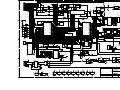
All of the functions of the 3012 are under control of microprocessors U4 and U5 which contain the firmware
operating system and interfaces to the rest of the hardware. U4 and U5 communicate with each other over a high
speed SPI (3-wire) data bus. U4 handles the radio interface, MSK signal processing, text messages, and LCD
display. U5 handles the keyboard input, the 5 status inputs, GPS receiver and storage, and PC programming.
MSK Data
U20 provides the MSK encoding/decoding as well as signal filtering. Microprocessor U4 communicates with U20
on pins 4 and 5. MSK transmit audio is generated by U20 output on pin 23 then amplified by U7A. Level control
is achieved with RV3. After amplification the audio is routed to the mobile radio for modulation.
Audio enters the 3012 on pin 6 of P1 and is high pass filtered by U6A which has a cut off frequency of 500 Hz and
a slope of 12db/octave. U6B and U6C are a 4 pole low pass filter with a cut off frequency of 2500 Hz and a slope
of 24db/octave. The filtered audio goes into U20 pin 13 an op-amp inverter with a gain of 0-20dB as determined
by RV1. U20 pin 7 sends an interrupt request to microprocessor U4 when data arrives for processing.
LCD Display
U4 sends data to the LCD on an 8 bit parallel data bus and 4 control pins. Data direction is controlled by pins
5 & 6 of the LCD. Device select and Command/Data are selected on pins 7 & 8 of the LCD. The LCD has an LED
backlight and requires 4VDC at 600mA. U22 is a step down converter that supplies a regulated 4V output from
an unregulated 12V input. Contrast control is accomplished by a negative voltage from inverter U8 and digital
pot U25 which is under control of µP U5.
Serial Data
The MDT communicates with the outside world on a number of data buses. The 3012 interfaces with a PC or printer
on P2 and with a mobile radio or CentryII data bus on P1. U21 changes the data level from RS232 to TTL level
for communications with the PC or printer. U1 selects the data path between the PC and U4 or U5 and is under
control of J6 (flash programming) or U5 (PC personalization). U5 also communicates with the GPS receiver and
U2 changes the data path from the PC to the GPS. U4 can communicate with the mobile radio data bus or the PC
and U3 selects the data path. The mobile radio data path can be either RS232 (U9 installed) or 5V TTL level
(U9 removed, J9 & J10 installed).
Keyboard Decoder
The 19 button keypad as used on the 3012 is decoded by U17. This chip will take the ROW and COLUMN lines
of the keypad and present a 5 bit parallel word to µP U5. The decoder is monitored by the STROBE line indicating
that a button has been pressed.
Memory
Six on-board E²PROMS provide data retention of programming information, text messages received and GPS
position history. Non-volatile data storage is contained in U18 (personalization data), U15 (text messages) and
U11-U14 (GPS data).
Page 21