1
THE DOCUMENT COMPANY
XEROX
Phaser 790/DocuColor 2006
Service Manual
October 2000
701P35949
CAUTION
Certain components in the Phaser 790/DocuColor
2006 are susceptible to damage from electrostatic
discharge. Observe all ESD procedures to avoid
component damage.
Prepared by:
Xerox Corporation
Global Knowledge & Language Services
800 Phillips Road Bldg. 845-17S
Webster, New York 14580-9791
USA
© 2000 by Xerox Corporation. All rights reserved. Copyright protection
claimed includes all forms and matters of copyrightable material and information now allowed by statutory or judicial law or hereinafter granted,
including without limitation, material generated from the software programs
that are displayed on the screen such as styles, templates, icons, screen
displays, looks, etc.
***XEROX DocuLock Protect Until Forever***
XEROX®, The Document Company®, the stylized X and the identifying
product names and numbers herein are trademarks of XEROX CORPORATION. Other company trademarks are also acknowledged.
NOTICE
While every care has been taken in the preparation of this manual, no liability will be accepted by Xerox Corporation arising out of any inaccuracies or
omissions.
NOTICE
All service documentation is supplied to Xerox external customers for informational purposes only. Xerox service documentation is intended for use by
certified product trained service personal only. Xerox does not warrant or
represent that such documentation is complete, nor does Xerox represent
or warrant that it will notify or provide to such customer any future changes
to this documentation. Customer performed service of equipment, or modules, components or parts of such equipment may affect the warranty
offered by Xerox with respect to such equipment. You should consult the
applicable warranty for its terms regarding customer or third party provided
service. If the customer services such equipment, modules, components or
parts thereof, the customer releases Xerox from any and all liability for the
customer actions, and the customer agrees to indemnify, defend and hold
Xerox harmless from any third party claims which arise directly or indirectly
from such service.
WARNING
This equipment generates, uses and can radiate radio frequency
energy, and if not installed and used in accordance with the instructions documentation, may cause interference to radio communications. It has been tested and found to comply with the limits for a
Class A computing device pursuant to subpart J of part 15 of FCC
rules, which are designed to provide reasonable protection against
such interference when operated in a commercial environment. Operation of this equipment in a residential area is likely to cause interference in which case the user, at his own expense, will be required to
correct the interference.
WARNING
This machine contains an invisible laser. There is no visual indication
that the laser beam is present. During servicing, the machine is a
Class 3B product because of the invisible laser. the laser beam could
cause eye damage if looked at directly. Service procedures must be
followed exactly as written without change. The service representative
must observe the established local laser safety precautions when servicing the machine. Do not place tools with a reflective surface into
the ROS opening. Do not look in the area of the ROS window if the
power is On and the laser is energized.
Introduction
About this Manual ...........................................................................................................
Organization ....................................................................................................................
How to Use this Documentation ......................................................................................
Symbology ......................................................................................................................
Initial Issue
Phaser 790/DocuColor 2006
iii
iii
iii
iii
10/00
i
Introduction
Introduction
10/00
ii
Initial Issue
Phaser 790/DocuColor 2006
About this Manual
Adjustments
This Service Manual is part of the multinational documentation system for the Phaser 790
Printer and DC 2006 Copier./Printer The Service Documentation is used in order to diagnose
machine malfunctions, adjust components and has information which is used to maintain the
product in superior operating condition. It is the controlling publication for a service call. Information on its use is found in the Introduction of the Service Documentation.
Adjustments include procedures for adjusting the parts that must be within specification for the
correct operation of the system.
Use the adjustment procedures for the correct sequence of operation for specifications, warnings, cautions and notes.
Section 5: Parts Lists
This manual contains information that applies to NASG and ESG copiers.
This section contains the Printer/Copier Parts List.
Service Manual Revision
The Service Manual will be updated as the machine changes or as problem areas are identified.
Section 6: General Procedures/Information
Organization
Section 7: Wiring Data
This Service Manual is divided into nine sections. The titles of the sections and a description of
the information contained in each section are contained in the following paragraphs:
This section contains drawings, lists of plug/jack locations, and diagrams of the power distribution wire networks in the machine. Individual wire networks are shown in the Circuit Diagrams
contained in Section 2. This section also contains the Block Schematic Diagrams.
This section contains General Procedures, Diagnostic Programs, and Copier Information.
Section 1 Service Call Procedures
This section contains procedures that determine what actions are to be taken during a service
call on the machine and in what sequence they are to be completed. This is the entry level for
all service calls.
How to Use this Documentation
Section 2 Status Indicator RAPs
Use of the Circuit Diagrams
This section contains the diagnostic aids for troubleshooting the Fault Code and non-Fault
Code related faults (with the exception of copy quality problems).
Circuit Diagrams (CDs) are included in Sections 2 (Status Indicator RAPs) and 3 (Image Quality RAPs) of the Service Manual. All wirenets, with the exception of power distribution wirenets,
are shown on the CDs. Power distribution wirenets are shown in Section 7 (Wiring Data) of the
Service Manual. The power distribution wirenets on the CDs will end at the terminal board for
the power being distributed. Find the wirenet for that power and locate the terminal board on
the wirenet. Use the wirenet to troubleshoot any power distribution wiring not shown on the
CD.
Section 3 Image Quality
This section contains the diagnostic aids for troubleshooting any copy quality problems, as well
as copy quality specifications and copy defect samples.
Section 4 Repairs/Adjustments
The Service Call Procedures in Section 1 describe the sequence of activities used during the
service call. The call must be entered using these procedures.
Use of the Block Schematic Diagrams
This section contains all the Adjustments and Repair procedures.
Repairs
Repairs include procedures for removal and replacement of parts which have the following
special conditions:
When removal or replacement cannot be determined from the exploded view of the
Parts List.
When there is a cleaning or a lubricating activity associated with the procedure.
Block Schematic Diagrams (BSDs) are included in Section 7 (Wiring Data) of the Service Manual. The BSDs show the functional relationship of the electrical circuitry to any mechanical, or
non-mechanical, inputs or outputs throughout the machine. Inputs and outputs such as motor
drive, mechanical linkages, operator actions, and air flow are shown. The BSDs will provide an
overall view of how the entire subsystem, such as ADF, works.
It should be noted that the BSDs no longer contain an Input Power Block referring to Chain 1. It
will be necessary to refer to the Wirenets in order to trace a wire back to its source.
When the part requires an adjustment after replacement.
Symbology
When a special tool is required for removal or replacement.
Use the repair procedures for the correct order of removal and replacement, for warnings, cautions, and notes.
Initial Issue
Phaser 790/DocuColor 2006
The following reference symbols are used throughout the documentation.
10/00
iii
Introduction
Warnings, Cautions, and Notes
Machine Safety Icons
Warnings, Cautions, and Notes will be found throughout the Service Documentation. The
words WARNING or CAUTION may be listed on an illustration when the specific component
associated with the potential hazard is pointed out; however, the message of the WARNING or
CAUTION is always located in the text. Their definitions are as follows:
The following safety icons are displayed on the machine:
WARNING
A Warning is used whenever an operating or maintenance procedure, a practice, condition, or statement, if not strictly observed, could result in personal injury.
CAUTION
A Caution is used whenever an operating or maintenance procedure, a practice, condition, or
statement, if not strictly observed, could result in damage to the equipment.
NOTE: A Note is used whenever it is necessary to highlight an operating or maintenance procedure, practice, condition, or statement.
Flags
The Flag symbol indicates a reference point into a Circuit Diagram from a RAP. Instructions will
be given to check for an open circuit, a short circuit, or an intermittent condition.
WARNING
The Phaser 790/Dc 2006 contains an invisible laser. There is no visual indication that the
laser beam is present. During servicing, the machine is a Class 3B product because of
the invisible laser. the laser beam could cause eye damage if looked at directly. Service
procedures must be followed exactly as written without change. The service representative must observe the established local laser safety precautions when servicing the
machine. Do not place tools with a reflective surface in the area of the Charge Corotron
or the ROS opening. Do not look in the area of the ROS window if the power is On and
the laser is energized.
The following symbol and statement appear on a label in the machine. The symbol by
itself, or the symbol and the statement may also appear in the service documentation
and in the training program. When this symbol appears, the service representative is
warned that conditions exist that could result in exposure to the laser beam.
WARNING
Do not try to bypass any laser interlocks for any reason. Permanent eye damage could
result if the laser is accidentally directed into your eye.
Note
This symbol refers to notes which are found on the same page as the Circuit Diagram.
Parts List
In this symbol, example (PL2.1), refers to the Parts List on which the part can be found.
Figure 1 Laser Hazard Symbol
Laser Hazard Statement
Adjustments
The adjustment symbol refers to an procedure in the Adjustment section of this Manual.
DANGER INVISIBLE LASER RADIATION WHEN OPEN. AVOID DIRECT EXPOSURE TO
BEAM.
Test Points, Test Stakes, Test Holes
This symbol is used to indicate that a test point, test stake, or test hole is available for accessing a signal line. The prefix before the identification number indicates whether the access is a
test point (TP), a test stake (TS), or a test hole (TH).
CAUTION
The use of controls or adjustments other than those specified in the Laser Safety Training Program may result in an exposure to dangerous laser radiation.
For additional information, review the Laser Safety Training program.
Bracket
The bracket symbol indicates a Component Control Code selection in a Diagnostic Program.
An arrow points to the location to install, to gain access to, or to release an object.
This symbol indicates that a surface can be hot. Use caution when reaching in the machine to
avoid touching the hot surfaces.
Introduction
10/00
iv
Initial Issue
Phaser 790/DocuColor 2006
Danger label indicates where electrical currents exist when the machine is closed and operating. Use caution when reaching in the machine.
These symbols indicate components that may be damaged by Electrostatic Discharge (ESD).
Electrostatic Discharge (ESD) Field Service Kit
The purpose of the ESD Protection Program is to preserve the inherent reliability and quality of
electronic components that are handled by the Field Service Personnel. This program is being
implemented now as a direct result of advances in microcircuitry technology, as well as a new
acknowledgment of the magnitude of the ESD problem in the electronics industry today.
This program will reduce Field Service costs that are charged to PWB failures. Ninety percent
of all PWB failures that are ESD related do not occur immediately. Using the ESD Field Service
Kit will eliminate these delayed failures and intermittent problems caused by ESD. This will
improve product reliability and reduce callbacks.
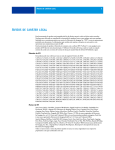
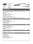
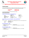
Figure 2 Signal Nomenclature
The ESD Field Service Kit should be used whenever Printed Wiring Boards or ESD sensitive
components are being handled. This includes activities like replacing or reseating of circuit
boards or connectors. The kit should also be used in order to prevent additional damage when
circuit boards are returned for repair.
The instructions for using the ESD Field Service Kit can be found in ESD Field Service Kit
Usage in the General Procedures section of the Service Documentation.
Signal Nomenclature
Refer to Figure 2 for an example of Signal Nomenclature.
Initial Issue
Phaser 790/DocuColor 2006
10/00
v
Introduction
Voltage Measurement and Specifications
DC Voltage Measurements in RAPs
Measurements of DC voltage must be made with reference to the specified DC Common,
unless some other point is referenced in a diagnostic procedure. All measurements of AC voltage should be made with respect to the adjacent return or ACN wire.
The RAPs have been designed so that when it is required to use the DMM to measure a DC
voltage, the first test point listed is the location for the red (+) meter lead and the second test
point is the location for the black meter lead. For example, the following statement may be
found in a RAP:
Table 1 Voltage Measurement and Specifications
VOLTAGE
There is +5 VDC from TP7 to TP68.
SPECIFICATION
INPUT POWER 220 V
198 VAC TO 242 VAC
INPUT POWER 100 V
90 VAC TO 135 VAC
INPUT POWER 120 V
90 VAC TO 135 VAC
+5 VDC
+4.75 VDC TO +5.25 VDC
+24 VDC
+23.37 VDC TO +27.06 VDC
In this example, the red meter lead would be placed on TP7 and the black meter lead on TP68.
Another example of a statement found in a RAP might be:
There is -15 VDC from TP21 to TP33.
Logic Voltage Levels
In this example, the red meter lead would be placed on TP21 and the black meter lead would
be placed on TP33.
Measurements of logic levels must be made with reference to the specified DC Common,
unless some other point is referenced in a diagnostic procedure.
If a second test point is not given, it is assumed that the black meter lead may be attached to
the copier frame.
Table 2 Logic Levels
VOLTAGE
H/L SPECIFICATIONS
+5 VDC
H= +3.00 TO +5.25 VDC
L= 0.0 TO 0.8 VDC
+24 VDC
H= +23.37 TO +27.06 VDC
L= 0.0 TO 0.8 VDC
Introduction
10/00
vi
Initial Issue
Phaser 790/DocuColor 2006
1 Service Call Procedures
Service Call Procedures..................................................................................................
Initial Actions Procedure .................................................................................................
Call Flow Procedure ........................................................................................................
Cleaning Procedures.......................................................................................................
Final Actions....................................................................................................................
Initial Issue
Phaser 790/DocuColor 2006
1-3
1-3
1-4
1-5
1-5
10/00
1-1
Service Call Procedures
Service Call Procedures
10/00
1-2
Initial Issue
Phaser 790/DocuColor 2006
Service Call Procedures
Initial Actions Procedure
Service Strategy
Purpose
The service strategy for the Phaser 790 Printer and the DC 2006 Copier/Printer is to run to failure. The Repair Analysis Procedures (RAPs) will be used to diagnose and repair any problems.
The purpose of the Initial Actions section of the Service Call Procedures is to determine the
reason for the service call and to identify and organize the actions which must be performed.
Procedure
Problems that occur in the Basic Printer mode will be repaired before problems that occur
when using the accessories.
1.
Gather the information about the service call and the condition of the copier/printer.
a.
Question the operator(s). Ask about the location of the most recent paper jams. Ask
about the image quality and the general performance of the copier/printer, including
any unusual sounds or other indications (if applicable).
Service Call Procedures
b.
The Service Call Procedures are a guide for performing any service on the Phaser 790
Printer and the DC 2006 Copier/Printer. The procedures are designed to be used with the
Phaser 790 Printer and the DC 2006 Copier/Printer Service Manual. Perform each step in
order.
Check that the power cords are in good condition, correctly plugged into the power
source, and free from any defects that would be a safety hazard. Repair or replace
the power cords as required. Check that the circuit breakers are not tripped.
c.
Ensure that all paper trays are loaded with paper.
d.
Inspect any rejected copies. Inquire as to, or otherwise determine, the paper quality
and weight. The specified paper for optimum image quality for the Phaser 790
Printer is Hammermill Laser Print 24. The specified paper for optimum image quality
for the DC 2006 Copier/Printer is 24# Xerox COLOR Xpressions or Colotech + 90
gms. Look for any damage to the copies, oil marks, image quality defects, or other
indications of a problem.
Call Flow
e.
Record the billing meter readings.
Call Flow summarizes the sequence of the Service Call Procedures.
f.
Check the Service Log for any recent activities that are related to the problem that
caused the service call or any secondary problem.
Image quality problems should be repaired after all other problems are repaired.
Initial Actions
The Initial Actions gather information about the condition of the machine and the problem that
caused the service call.
2.
Cleaning Procedures
The cleaning procedures list what needs to be cleaned at each service call.
Final Actions
The Final Actions will test the copier/printer and return it to the customer. Administrative activities are also performed in the Final Actions.
Initial Issue
Phaser 790/DocuColor 2006
Check the Image Quality by performing the Visual Calibration (GP 16).
a.
Run four copies of the 82E13030 Test Pattern.
b.
Check the image quality. If the customer has identified any Image Quality Defects or
problems, go to the IQ1 Image Quality Entry RAP.
3.
If there is a problem in the Basic Printer Mode, go to the Call Flow Procedure.
4.
If there are no problems in the Basic Printer Mode, go to the Final Actions.
10/00
1-3
Service Call Procedures
Service Call Procedures, Initial Actions Procedure
A
Call Flow Procedure
This procedure should be performed at every service call.
C
D
E
F
Go to the area where the noise is being generated and troubleshoot
that area.
If a sorter fault code is present, go to the RAP associated with that fault
code.
If a sorter message is present, go to the Section 2, Fault Message/RAP
Cross-Reference Table.
Procedure
The copier/printer is capable of making a copy/print to the Output Tray.
Y
N
The copier/printer is capable of making a copy/print to the Top Tray.
Y
N
The problem is in the paper path.
Y
N
A Fault Code or a message is constantly displayed.
Y
N
The Display is blank or garbled.
Y
N
If one or more of the buttons or LEDs does not function, go to the
002-702 IOT Control Panel Button/LED RAP.
Check for mechanical binding.
Check the ADF Document Sensors for debris or damage.
Check that the document mechanical drives and feed rolls are free from wear, damage, contamination, and binding.
Check the paper path sensors for debris or damage. Check that paper is loaded in all
trays correctly.
Check the paper path mechanical drives and rolls for contamination, glazing, wear, damage, or binding.
Go to the IQ1 Image Quality Entry RAP.
Go to the 002-701 Blank/Garbled IOT Display RAP.
If a fault code is displayed, go to the Fault Code RAP for the Fault Code that is
displayed.
If a message is displayed, go to the Fault Message/RAP Cross-Reference in
Section 2.
B
If a fault code is displayed, go to the Fault Code RAP for the Fault Code that is displayed.
If a message is displayed, go to the Fault Message/RAP Cross-Reference in Section 2.
Check the paper path sensors for debris or damage. Check that paper is loaded in
all trays correctly.
Check the paper path mechanical drives and rolls for contamination, glazing, wear, damage, or binding.
The copier is capable of making a copy/print to the Top Tray.
Y
N
Check the paper path mechanical drives and rolls for contamination, glazing, wear, damage, or binding.
A Fault Code or message is constantly displayed.
Y
N
The problem is Image Quality.
Y
N
The problem is in the ADF.
Y
N
The problem is in the Scanner.
Y
N
The problem is in the Sorter.
Y
N
The problem is noise.
Y
N
The problem is intermittent. Go to the BSD and perform a resistance check of the wires in question. Gently pull on the wires to
ensure that they are properly connected.
A
B
C
D
E
F
Service Call Procedures
Call Flow Procedure
10/00
1-4
Initial Issue
Phaser 790/DocuColor 2006
Cleaning Procedures
Final Actions
Purpose
Purpose
The purpose is to provide cleaning procedures to be performed at every call.
The intent of this procedure is to be used as a guide to follow at the end of every service call.
Procedure
Procedure
CAUTION
1.
Ensure that the exterior of the copier/printer and the adjacent area are clean. Use a dry
cloth or a cloth moistened with water to clean the copier/printer. Do not use solvents.
General Cleaning
2.
Check the supply of consumables. Ensure that an adequate supply of consumables is
available according to local operating procedures.
Use a dry lint free cloth or a lint free cloth moistened with water for all cleaning unless directed
otherwise by the Service Manual. Wipe with a dry lint free cloth if a moistened cloth is used.
3.
Conduct any operator training that is needed. Ensure that the operator understands that
the VisualCal procedure in the Operator Manual should be used to adjust the colors.
Ensure that the operator can perform the VisualCal procedure (reference the GP 16
Visual Calibration procedure).
Do not use any solvents unless directed to do so by the Service Manual.
1.
2.
3.
Feed Components (Rolls and Pads)
Follow the General Cleaning procedure above.
4.
Complete the Service Log.
Dry Ink Dispense Units
5.
Vacuum the Dry Ink Dispense units.
Perform the following steps to make a copy of the Demonstration Original for the Customer:
Jam Sensors
a.
Load Paper in Tray 1 with 8-1/2 x 11 inch (A4) or 11 x 17 inch, 24# Xerox COLOR
Xpressions or Colotech + 90 gms for the DC 2006 Copier/Printer, or Hammermill
Laser Print 24 for the Phaser 790
b.
Place Test Pattern 82E13030 on the glass with the short edge of the test pattern registered to the left edge of the glass. Select Tray 1 and make a single copy.
Clean the sensors with a dry cotton swab.
4.
IBT Cleaning
Check the IBT Belt surface and wipe with a dry lint free cloth. If the surface is excessively
dirty, replace the IBT Belt (PL 7.2).
5.
Fuser Components (best cleaned when hot).
Wipe with a lint free cloth.
6.
7.
Scanner
a.
Switch off the power and allow the Exposure Lamp to cool off.
b.
Using the optical Cleaning Cloth, clean the front and rear of the Document Glass,
Document Cover, White Reference Strip, Reflector, and Mirror.
c.
Clean the Exposure Lamp with a clean cloth and Film Remover.
c.
Print a Configuration Page (GP 14).
d.
Print a test page (for the printer only).
e.
Present the copies to the customer.
6.
Issue copy credits as needed.
7.
Discuss the service call with the customer to ensure that the customer understands what
has been done and is satisfied with the results of the service call.
ADF
Check the paper path for debris or damage. Clean the rolls with a clean cloth and Film
Remover as required.
8.
Sorter
Check the paper path for debris or damage. Clean the Sorter with a dry lint free cloth.
Initial Issue
Phaser 790/DocuColor 2006
10/00
1-5
Service Call Procedures
Cleaning Procedures, Final Actions
Service Call Procedures
Cleaning Procedures, Final Actions
10/00
1-6
Initial Issue
Phaser 790/DocuColor 2006
2 Status Indicator RAPs
Fault Message Cross-reference
Fault Message/RAP Cross-Reference ............................................................................
2-3
Standby Power
001-701 AC Power RAP .................................................................................................
001-702 +5 VDC Power RAP..........................................................................................
001-703 +24 VDC Interlocked Power RAP .....................................................................
001-704 Front Cover Open RAP .....................................................................................
001-705 ROS +5 VDC Switched Voltage RAP ...............................................................
001-706 Area 1 Open RAP .............................................................................................
001-707 Area 2 Open RAP .............................................................................................
001-708 Area 3 Open RAP .............................................................................................
001-709 Area 4 Open RAP .............................................................................................
001-710 Area 5 Open RAP .............................................................................................
001-711 Area 6 Open RAP .............................................................................................
001-712 IIT DC Power RAP ............................................................................................
2-5
2-7
2-9
2-11
2-13
2-15
2-17
2-19
2-21
2-23
2-25
2-27
User Interface
002-310 IIT Control Panel Failure RAP...........................................................................
002-701 Blank/Garbled IOT Display RAP .......................................................................
002-702 IOT Control Panel Button/LED RAP .................................................................
2-29
2-29
2-31
Machine Run Control
003-310 Feeder Communications Failure RAP ..............................................................
003-311 Duplex Communications Failure RAP...............................................................
003-312 Sorter Communications Failure RAP ................................................................
003-333 Foreign Interface RAP ......................................................................................
003-334 Foreign Interface Compatibility RAP.................................................................
003-356 IOT NVM RAM Error RAP.................................................................................
003-400 IOT Firmware Error RAP...................................................................................
003-701 Copy/Print Cartridge Error RAP ........................................................................
2-33
2-35
2-37
2-39
2-41
2-43
2-45
2-45
Start Print Power
004-320 Paper Handling Motor RAP...............................................................................
004-322 Fuser Motor RAP ..............................................................................................
2-47
2-49
Document Transportation
005-210 Nudger Home RAP ...........................................................................................
005-211 ADF Power RAP ...............................................................................................
005-220/221 ADF Communications RAP........................................................................
005-700 ADF Fault Entry RAP ........................................................................................
005-701 ADF Entrance Jam RAP ...................................................................................
005-702 ADF Exit Jam RAP............................................................................................
005-703 ADF No Feed RAP............................................................................................
005-704 Unfinished Copy Job RAP ................................................................................
2-51
2-53
2-55
2-57
2-58
2-60
2-62
2-64
Imaging
006-310 IIT Registration RAP .........................................................................................
006-311 Exposure Lamp RAP ........................................................................................
Initial Issue
Phaser 790/DocuColor 2006
2-67
2-69
006-312 FPC CCD RAP..................................................................................................
006-313 IIT Cooling Fans RAP .......................................................................................
006-372 Start of Scan Error RAP ....................................................................................
006-701 Angle Sensor RAP ............................................................................................
006-702 Platen Switch RAP ............................................................................................
006-703 Scanner Error RAP ...........................................................................................
006-704 System Error (093-XXX) RAP ...........................................................................
006-906/907/908/909 RAP..............................................................................................
2-70
2-71
2-73
2-75
2-77
2-79
2-79
2-80
Paper Supply
007-324 Environment Sensor RAP .................................................................................
007-340 Feeder Motor Fail RAP .....................................................................................
007-341 Inverter Motor Fail RAP.....................................................................................
007-700 Tray 1 Open RAP..............................................................................................
007-701 Tray 2 Open RAP..............................................................................................
007-702 Tray 3 Open RAP..............................................................................................
007-703 Tray 1 Empty RAP ............................................................................................
007-704 Tray 2 Empty RAP ............................................................................................
007-705 Tray 3 Empty RAP ............................................................................................
007-706 Bypass Tray Empty RAP...................................................................................
007-707 Paper Length Mismatch RAP............................................................................
007-708 Bypass Tray Lift RAP ........................................................................................
007-709 Tray 2 Lift Up RAP ............................................................................................
007-710 Tray 3 Lift Up RAP ............................................................................................
007-711 Tray 1 Paper Size Not Detected RAP ...............................................................
007-712 Tray 2 Paper Size Not Detected RAP ...............................................................
007-713 Tray 3 Paper Size Not Detected RAP ...............................................................
2-81
2-83
2-85
2-87
2-89
2-91
2-93
2-95
2-97
2-99
2-101
2-102
2-104
2-107
2-110
2-112
2-114
Paper Transportation
008-700 Area 1 Jam RAP ...............................................................................................
008-701 Area 2 Jam RAP ...............................................................................................
008-702 Area 3 Jam RAP ...............................................................................................
008-703 Area 4 Jam RAP ...............................................................................................
008-704 Area 6 Jam RAP ...............................................................................................
008-705 Top Tray Full RAP.............................................................................................
008-706 OHP Sensor RAP..............................................................................................
008-707 Duplex Tray Open RAP.....................................................................................
2-117
2-120
2-123
2-125
2-127
2-130
2-132
2-134
Xerographics
009-321 TR0 Sensor RAP...............................................................................................
009-323 Process Motor RAP...........................................................................................
009-326 Rotary Motor RAP .............................................................................................
009-340 ADC Cleaning Failure RAP ...............................................................................
009-341 ADC Sensor Background RAP..........................................................................
009-342 Patch Error RAP................................................................................................
009-343 PCDC Error RAP...............................................................................................
009-344 Image Density Error RAP..................................................................................
009-358 BTR 2 Home Position RAP ...............................................................................
10/00
2-1
2-137
2-139
2-141
2-143
2-145
2-147
2-149
2-149
2-150
Status Indicator RAPs
009-359 BTR 2 Bias RAP ...............................................................................................
009-360 Developer Fan RAP ..........................................................................................
009-700 Toner Cartridge Detached RAP ........................................................................
009-701 Toner Cartridge Empty RAP .............................................................................
009-702 Waste Container Full RAP ................................................................................
009-703 Waste Container Detached RAP ......................................................................
009-704 Belt Cleaner RAP..............................................................................................
2-152
2-154
2-156
2-158
2-160
2-162
2-164
Fusing and Copy Transportation
010-317 Temperature Sensor Circuit Error RAP ............................................................
010-353/356/357 Fuser Low/Under Temperature Condition RAP ..................................
010-354 Fuser Temperature Not Detected RAP.............................................................
010-355 Fuser Overheat Error RAP................................................................................
010-358 Fuser Fan Error RAP ........................................................................................
010-359 Exit Chute Fan Failure RAP ..............................................................................
010-700 Area 5 Jam RAP ...............................................................................................
010-701 Faulty Temperature Sensor RAP ......................................................................
010-702 Faulty Entrance Sensor RAP ............................................................................
010-703 Faulty Fuser Exit Sensor RAP ..........................................................................
010-704 Faulty Fuser Chute Fan RAP............................................................................
010-705 Faulty Exchange Solenoid RAP........................................................................
2-167
2-168
2-170
2-172
2-174
2-176
2-178
2-180
2-182
2-184
2-186
2-188
Sorter
011-700 Sorter Not In Correct Position RAP...................................................................
011-701 Sorter Bin Jam RAP ..........................................................................................
011-702 Sorter Cover Open RAP ...................................................................................
011-703 Sorter Transport Jam RAP................................................................................
011-704 Sorter Noise RAP..............................................................................................
011-705 Full Sensor RAP ...............................................................................................
011-706 Cannot Select Sorter RAP ................................................................................
2-191
2-193
2-196
2-198
2-200
2-202
2-204
Imaging Control
016-310 Font ROM Checksum Error RAP ......................................................................
016-312 ESS Hard Drive Error RAP ...............................................................................
016-313 ASIC Access Error RAP....................................................................................
016-315 ESS RAM (Bank 1) RAP...................................................................................
016-316 ESS RAM (Bank 2) RAP...................................................................................
016-317 ESS ROM RAP .................................................................................................
016-323/324/325 ESS NVM RAM Failure RAP ..............................................................
016-330/331/332/333/334/335/336 Interface Error RAP.................................................
016-370 IOT to ESS Communication Failure RAP .........................................................
2-207
2-207
2-208
2-208
2-209
2-209
2-210
2-210
2-211
IIT Communications
033-210 Printer Detection RAP.......................................................................................
033-211/212 IOT/IIT Disconnection RAP........................................................................
033-221/222/223/224/225/226/226/227/228 IOT/IIT Communication RAP ....................
033-330/331/332 Software Error RAP ............................................................................
033-340/341/342/343/344/345/350 ASIC Error RAP ......................................................
033-360/361/370/371 Memory Error RAP.......................................................................
033-380/390 1394 Failure RAP.......................................................................................
033-921/922/930/934/935/936/937 IOT/IIT Communication RAP ..................................
033-940/941/943/944/945 SCSI Error RAP ....................................................................
Status Indicator RAPs
2-213
2-213
2-214
2-214
2-215
2-215
2-216
2-216
2-217
10/00
2-2
Initial Issue
Phaser 790/DocuColor 2006
Fault Message/RAP Cross-Reference
Table 1
NOTE: For all ADF Jam messages displayed on the Scanner Display, go to the 005-700 RAP.
For all Scanner Error messages displayed on the Scanner Display, which do not have an
associated Fault Code RAP, go to the 006-703 RAP.
For all System Error (093-XXX) messages displayed on the Scanner Display, go to the 006704 RAP.
If the message on the IOT display contains a numeric fault code, go to the RAP for that code.
To find the appropriate RAP for an unclearable message that does not contain a fault code, go
to Table 1. Locate the message in column one, and go to the RAP listed in column two.
Table 1
If this message is displayed
Go to this RAP
Check Loading of <tray> In Use
007-707 Paper Length Mismatch RAP
Check Sorter Position
011-700 Sorter Not In Correct Position RAP
Clear Jam In Area 1
008-700 Area 1 Jam RAP
Clear Jam In Area 2
008-701 Area 2 Jam RAP
Clear Jam In Area 3
008-702 Area 3 Jam RAP
Clear Jam In Area 4
008-703 Area 4 Jam RAP
Clear Jam In Area 5
010-700 Area 5 Jam RAP
Clear Jam In Area 6
008-704 Area 6 Jam RAP
Clear Jam In Duplex Tray
008-707 Duplex Tray Jam RAP
Close Area 1
001-706 Area 1 Open RAP
Close Area 2
001-707 Area 2 Open RAP
Close Area 3
001-708 Area 3 Open RAP
Close Area 4
001-709 Area 4 Open RAP
Close Area 5
001-710 Area 5 Open RAP
Close Area 6
001-711 Area 6 Open RAP
Close Duplex Tray
008-707 Duplex Tray Open RAP
Close Front Cover
001-704 Front Cover Open RAP
Close Paper Tray 1
007-700 Tray 1 Open RAP
Close Paper Tray 2
007-701 Tray 2 Open RAP
Close Paper Tray 3
007-702 Tray 3 Open RAP
Close Sorter Cover
011-702 Sorter Top Cover Open RAP
Empty Sorter Bins
011-701 Sorter Bin Jam RAP
Empty Stacker Tray
011-705 Full Sensor RAP
Empty Top Tray
008-705 Top Tray Full RAP
Install <color> Ink Cartridge
009-700 Toner Cartridge Detached RAP
Install Copy/Print Cartridge
003-701 Copy/Print Cartridge Error RAP
Install Waste Container
009-703 Waste Container Detached RAP
Jam in Sorter
011-701 Sorter Bin Jam RAP
Load <size>
007-711 Tray 1 Paper Size Not Detected RAP
007-712 Tray 2 Paper Size Not Detected RAP
007-713 Tray 3 Paper Size Not Detected RAP
Initial Issue
Phaser 790/DocuColor 2006
10/00
2-3
If this message is displayed
Go to this RAP
Load <size> In Bypass Tray
007-706 Bypass Tray Empty RAP
Load <size> In Tray 1
007-703 Tray 1 Empty RAP
Load <size> In Tray 2
007-704 Tray 2 Empty RAP
Load <size> In Tray 3
007-705 Tray 3 Empty RAP
Order Copy/Print Cartridge
003-701 Copy/Print Cartridge Error RAP
Reload <size> in Bypass Tray
007-708 Bypass Tray Lift RAP
Reload <size> in Tray 2
007-709 Tray 2 Lift Up RAP
Reload <size> In Tray 3
007-710 Tray 3 Lift Up RAP
Replace Copy/Print Cartridge
003-701 Copy/Print Cartridge Error RAP
Waste Container Full
009-702 Waste Container Full RAP
Status Indicator RAPs
Fault Message/RAP Cross-Reference
Status Indicator RAPs
Fault Message/RAP Cross-Reference
10/00
2-4
Initial Issue
Phaser 790/DocuColor 2006
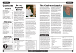
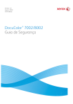
001-701 AC Power RAP
Initial Actions
•
Ensure AC Power is available at the wall receptacle.
•
Ensure the Power Cord is good. Replace the Power Cord if it is defective (PL 11.1).
Procedure
Switch off the power. Remove the Rear Cover. Switch on the power. If AC Power is not measured at J34-2 to terminal N on the Low Voltage Power Supply, replace the Low Voltage Power
Supply (PL 11.1).
Initial Issue
Phaser 790/DocuColor 2006
10/00
2-5
Status Indicator RAPs
001-701
Figure 1 001-701 Circuit Diagram
Status Indicator RAPs
001-701
10/00
2-6
Initial Issue
Phaser 790/DocuColor 2006
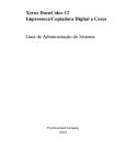
001-702 +5 VDC Power RAP
Initial Actions
•
Ensure AC Power is available at the wall receptacle.
•
Ensure the Power Cord is good. Replace the Power Cord if it is defective (PL 11.1).
Procedure
Switch off the power. Remove the Rear Cover. Switch on the power. +5 VDC is measured
between J33-1 and J33-4.
Y
N
Switch off the power. Disconnect J32 and J33 from the Low Voltage Power Supply. Switch
on the power. +5 VDC is measured between P33-1 and P33-4 on the Low Voltage
Power Supply.
Y
N
Replace the Low Voltage Power Supply (PL 11.1).
Switch off the power. Reconnect J32 to the Low Voltage Power Supply. Switch on the
power. +5 VDC is measured between P33-1 and P33-4 on the Low Voltage Power
Supply.
Y
N
Go to Flag 2. Refer to the +5 VDC Wirenet to troubleshoot a short circuit in the wires
from P32.
Go to Flag 1. Refer to the +5 VDC Wirenet to troubleshoot a short circuit in the wires from
P33.
The Low Voltage Power Supply appears to be operating correctly.
Initial Issue
Phaser 790/DocuColor 2006
10/00
2-7
Status Indicator RAPs
001-702
Figure 1 001-702 Circuit Diagram
Status Indicator RAPs
001-702
10/00
2-8
Initial Issue
Phaser 790/DocuColor 2006
001-703 +24 VDC Interlocked Power RAP
Initial Actions
Ensure the Left Front Cover, the Registration/Bypass Tray Drawer, and the Main Fuser Assembly are closed and in the correct position.
Ensure that the actuator for the Left Front Cover Interlock is not broken.
Procedure
Switch off the power. Remove the Rear Cover. Switch on the power. +24 VDC is measured
between J32-5 on the Low Voltage Power Supply and machine frame.
Y
N
+5.0 VDC is measured between J32-18 and machine frame.
Y
N
Approximately +4.4 VDC is measured between J32-16 and machine frame.
Y
N
Go to Flag 6. Check the wire for an open circuit. If the wire is good, replace the
MCU PWB (PL 11.2).
Replace the Low Voltage Power Supply (PL 11.1).
+5.0 VDC is measured between J33-9 on the Low Voltage Power Supply and
machine frame.
Y
N
+5.0 VDC is measured between J199-1 (brown wire) on the Left Front Cover
Interlock and machine frame.
Y
N
Go to Flag 5. Check the wire for an open circuit.
+5.0 VDC is measured between J198-1 (yellow wire) on the Left Front Cover
Interlock and machine frame.
Y
N
Replace the Left Front Cover Interlock (PL 11.1).
Check the following:
•
Go to Flag 2, Flag 3, and Flag 4. Check the wires for an open circuit.
•
If the wires are good, check the connectors between the Low Voltage Power
Supply and the Left Front Cover Interlock for bent or broken pins or for damaged connectors (P/J70, P/J71, P/J97, and P/J91).
Replace the Low Voltage Power Supply (PL 11.1).
The Low Voltage Power Supply appears to be operating correctly.
Initial Issue
Phaser 790/DocuColor 2006
10/00
2-9
Status Indicator RAPs
001-703
Figure 1 001-703 Circuit Diagram
Status Indicator RAPs
001-703
10/00
2-10
Initial Issue
Phaser 790/DocuColor 2006
001-704 Front Cover Open RAP
Initial Actions
Ensure the Right Front Cover is closed and that the actuator for the interlock is not damaged.
Procedure
Access the Digital Input (DI) test from the Control Panel. Enter code [73]. Press the Item/Enter
button. The display indicates 0.
Y
N
Go to Flag 1 and Flag 2 and check the wires for an open circuit. If the wires are good,
replace the Right Front Cover Interlock (PL 11.2). If the problem continues, replace the
MCU PWB (PL 11.2).
The problem may be intermittent. Go to Flag 1 and Flag 2 and check for loose or damaged
connections or damaged wires. If the problem persists, replace the Right Front Cover Interlock
(PL 11.2). If the problem continues, replace the MCU PWB (PL 11.2).
Initial Issue
Phaser 790/DocuColor 2006
10/00
2-11
Status Indicator RAPs
001-704
Figure 1 001-704 Circuit Diagram
Status Indicator RAPs
001-704
10/00
2-12
Initial Issue
Phaser 790/DocuColor 2006
001-705 ROS +5 VDC Switched Voltage RAP
Initial Actions
Check the following:
•
Ensure the Right Front Cover is closed.
•
Ensure the Top Cover is correctly positioned and is actuating the Top Cover Interlock.
Procedure
Switch off the power. Remove the Rear Cover. Switch on the power. +5 VDC is measured
between J32-22 on the Low Voltage Power Supply and machine frame.
Y
N
Replace the Low Voltage Power Supply (PL 11.1).
Remove the Top Cover. Actuate the Top Cover Interlock. +5 VDC is measured between
J125-1 on the ROS Assembly and machine frame.
Y
N
With the Top Cover Interlock still actuated, +5 VDC is measured between FS2 (blue
wire) on the Top Cover Interlock and machine frame.
Y
N
+5 VDC is measured between FS1 (blue wire) on the Top Cover Interlock and
machine frame.
Y
N
+5 VDC is measured between J194-1 (blue wire) on the Right Front Cover
Interlock and machine frame.
Y
N
+5 VDC is measured between J193-1 (brown wire) on the Right Front
Cover Interlock and machine frame.
Y
N
Go to Flag 3. Check the wire for an open circuit.
Replace the Right Front Cover Interlock (PL 11.2).
Go to Flag 2. Check the wire for an open circuit.
Replace the Top Cover Interlock (PL 11.1).
Go to Flag 1. Check the wire for an open circuit.
The ROS +5 VDC Switched circuit appears to be functioning correctly.
Initial Issue
Phaser 790/DocuColor 2006
10/00
2-13
Status Indicator RAPs
001-705
Figure 1 001-705 Circuit Diagram
Status Indicator RAPs
001-705
10/00
2-14
Initial Issue
Phaser 790/DocuColor 2006
001-706 Area 1 Open RAP
Initial Actions
Perform the following:
•
Check the actuator for the Bypass Tray Interlock. Ensure it is not broken or damaged.
•
Ensure the Bypass Tray is closed and is in the operating position.
Procedure
Access the Digital Input (DI) test from the Control Panel. Enter code [77]. Press the Item/Enter
button. The display indicates 0.
Y
N
Go to Flag 1 and Flag 2. Check the wires for an open circuit. If the wires are good, replace
the Bypass Tray Interlock (PL 4.1). If the problem continues, replace the MCU PWB (PL
11.2).
The problem may be intermittent. Go to Flag 1 and Flag 2 and check for loose or damaged
connections or damaged wires. If the problem persists, replace the Bypass Tray Interlock (PL
4.1). If the problem continues, replace the MCU PWB (PL 11.2).
Initial Issue
Phaser 790/DocuColor 2006
10/00
2-15
Status Indicator RAPs
001-706
Figure 1 001-706 Circuit Diagram
Status Indicator RAPs
001-706
10/00
2-16
Initial Issue
Phaser 790/DocuColor 2006
001-707 Area 2 Open RAP
Initial Actions
Perform the following:
•
Check the actuator for the Turn Chute Interlock. Ensure it is not broken or damaged.
•
Ensure the Turn Chute is closed.
Procedure
Access the Digital Input (DI) test from the Control Panel. Enter code [84]. Press the Item/Enter
button. The display indicates 0.
Y
N
Go to Flag 1 and Flag 2. Check the wires for an open circuit. If the wires are good, replace
the Turn Chute Interlock (PL 3.3). If the problem continues, replace the MCU PWB (PL
11.2).
The problem may be intermittent. Go to Flag 1 and Flag 2 and check for loose or damaged
connections or damaged wires. If the problem persists, replace the Turn Chute Interlock (PL
3.3). If the problem continues, replace the MCU PWB (PL 11.2).
Initial Issue
Phaser 790/DocuColor 2006
10/00
2-17
Status Indicator RAPs
001-707
Figure 1 001-707 Circuit Diagram
Status Indicator RAPs
001-707
10/00
2-18
Initial Issue
Phaser 790/DocuColor 2006
001-708 Area 3 Open RAP
Initial Actions
Perform the following:
•
Ensure the Right Cover is fully closed.
•
Check the actuators for both Feeder Right Cover Switches. Ensure they are not broken or
damaged.
Procedure
Access the Digital Input (DI) test from the Control Panel. Enter code [C0]. Press the Item/Enter
button. The display indicates 0.
Y
N
Remove the Feeder Rear Cover (PL 13.2). Less than +1.0 VDC is measured between
J217-8 on the Feeder PWB and machine frame.
Y
N
Go to Flag 1. Check the wires for an open circuit. If the wires are good, replace the
Feeder Right Cover Interlock 1 (PL 13.2).
Replace the Feeder PWB (PL 13.4).
Enter code [C1]. Press the Item/Enter button. The display indicates 0.
Y
N
Remove the Feeder Rear Cover. Less than +1.0 VDC is measured between J217-10
on the Feeder PWB and machine frame.
Y
N
Go to Flag 2. Check the wires for an open circuit. If the wires are good, replace the
Feeder Right Cover Interlock 2 (PL 13.2).
Replace the Feeder PWB (PL 13.4).
The problem may be intermittent. Go to Figure 1 and check for loose or damaged connections
or damaged wires. If the problem persists, replace the Feeder Right Cover Interlock 1 and 2
(PL 13.2). If the problem continues, replace the Feeder PWB (PL 13.4).
Initial Issue
Phaser 790/DocuColor 2006
10/00
2-19
Status Indicator RAPs
001-708
Figure 1 001-708 Circuit Diagram
Status Indicator RAPs
001-708
10/00
2-20
Initial Issue
Phaser 790/DocuColor 2006
001-709 Area 4 Open RAP
Initial Actions
Perform the following:
•
Check the actuator for the Exit Chute Interlock. Ensure it is not broken or damaged.
•
Ensure the Exit Chute is closed.
Procedure
Access the Digital Input (DI) test from the Control Panel. Enter code [74]. Press the Item/Enter
button. The display indicates 0.
Y
N
Go to Flag 1 and Flag 2. Check the wires for an open circuit. If the wires are good, replace
the Exit Chute Interlock (PL 9.2). If the problem continues, replace the MCU PWB (PL
11.2).
The problem may be intermittent. Go to Flag 1 and Flag 2 and check for loose or damaged
connections or damaged wires. If the problem persists, replace the Exit Chute Interlock (PL
9.2). If the problem continues, replace the MCU PWB (PL 11.2).
Initial Issue
Phaser 790/DocuColor 2006
10/00
2-21
Status Indicator RAPs
001-709
Figure 1 001-709 Circuit Diagram
Status Indicator RAPs
001-709
10/00
2-22
Initial Issue
Phaser 790/DocuColor 2006
001-710 Area 5 Open RAP
The Control Logic detected that the Fuser Drawer in not fully closed.
Initial Actions
Perform the following:
•
Ensure that the Fuser Assembly is fully closed.
•
Ensure that the Fuser Assembly is mounted correctly and securely. Repair any obvious
defects.
Procedure
Access the Digital Input (DI) test from the Control Panel. Enter code [62]. Press the Item/Enter
button. The display indicates 0.
Y
N
Go to Flag 1 and check the wire for a open circuit. If the wire is good, replace the MCU
PWB (PL 11.2).
The problem may be intermittent. Go to Flag 1 and check for loose or damaged connections or
damaged wires. If the problem persists, replace the MCU PWB (PL 11.2).
Initial Issue
Phaser 790/DocuColor 2006
10/00
2-23
Status Indicator RAPs
001-710
Figure 1 001-710 Circuit Diagram
Status Indicator RAPs
001-710
10/00
2-24
Initial Issue
Phaser 790/DocuColor 2006
001-711 Area 6 Open RAP
The Control Logic has detected that area 6 is open.
Initial Actions
Perform the following:
•
Ensure that the Inverter Chute (PL 15.5) is fully closed.
•
Ensure that the actuator for the CAB Interlock is not broken. Repair any obvious defects.
Procedure
Access the Digital Input (DI) test from the Control Panel. Enter code [93]. Press the Item/Enter
button. The display indicates 0.
Y
N
Go to Flag 1 and Flag 2. Check the wires for a open circuit. If the wires are good, replace
the Duplex Controller PWB (PL 15.6).
The problem may be intermittent. Go to Flag 1 and Flag 2 and check for loose or damaged
connections or damaged wires. If the problem persists, replace the replace the Duplex Controller PWB (PL 15.6).
Initial Issue
Phaser 790/DocuColor 2006
10/00
2-25
Status Indicator RAPs
001-711
Figure 1 001-711 Circuit Diagram
Status Indicator RAPs
001-711
10/00
2-26
Initial Issue
Phaser 790/DocuColor 2006
001-712 IIT DC Power RAP
Initial Actions
Ensure AC power is available at the wall outlet.
Ensure that the AC Power Cord is securely connected to the system.
Procedure
Remove the Rear Cover (REP 6.4) from the IIT. Check the following voltages at P91 (Figure 1)
on the IIT LVPS:
•
P91-1 (Orange Wire) for +24 VDC
•
P91-2 (Orange Wire) for +24 VDC
•
P91-3 (Gray Wire) for +5 VDC
•
P91-4 (Gray Wire) for +3.5 VDC
All of the voltage are available.
Y
N
All of the voltages are missing.
Y
N
Check the pins on connector P/J91. Look for loose or damaged pins. If the connector
is OK, replace the IIT LVPS (PL 16.1).
Check the Fuse (Figure 1) on the IIT LVPS. The Fuse is defective.
Y
N
AC line voltage is available between JN1-1 and JN1-2 (Figure 1).
Y
N
Replace the AC Switch/Harness (PL 16.6).
Replace the IIT LVPS (PL 16.1).
Replace the Fuse. If the Fuse blows again, replace the IIT LVPS (PL 16.1).
Go to the wirenets to check for any wires that may be open.
Check the IIT LVPS connectors for any loose or damaged pins.
Initial Issue
Phaser 790/DocuColor 2006
10/00
2-27
Status Indicator RAPs
001-712
Figure 1 001-712 Circuit Diagram
Status Indicator RAPs
001-712
10/00
2-28
Initial Issue
Phaser 790/DocuColor 2006
002-310 IIT Control Panel Failure RAP
002-701 Blank/Garbled IOT Display RAP
The IIT Control Panel has failed.
Initial Actions
Procedure
Remove the Right Cover (REP 14.9) in order to check the LEDs on the ESS PWB (Figure 1).
LED D5 (red LED) should not be lit and LED D4 (green LED) should be lit. If LED D5 is lit, or is
flashing, replace the ESS PWB (PL 12.1).
Check the cable between the ICM Main PWB and the Control Panel for any pinched wires.
Check the connectors for any loose or damaged pins. If the harness and connectors are good,
replace the Control Panel Assembly (PL 16.6).
Procedure
The Control Panel is blank.
Y
N
Reseat the Panel Harness between the ESS PWB and the Control Panel. If the problem
continues, replace the following components in the order listed until the problem is
resolved:
•
Panel Harness (PL 12.1)
•
Control Panel (PL 1.2)
•
ESS PWB (PL 12.1)
NOTE: The following voltage measurement is made at the solder points for J11 on the ESS
PWB. Refer to the Circuit Diagram for the correct location to make the measurements.
+5 VDC is measured between J11 pins A1, A2, B1, and B2 on the ESS PWB to machine
frame.
Y
N
Go to the 001-702 +5 VDC Power RAP.
Reseat the Panel Harness between the ESS PWB and the Control Panel. If the problem continues, replace the following components in the order listed until the problem is resolved:
•
Panel Harness (PL 12.1)
Initial Issue
Phaser 790/DocuColor 2006
•
Control Panel (PL 1.2)
•
ESS PWB (PL 12.1)
10/00
2-29
Status Indicator RAPs
002-310, 002-701
Figure 1 002-701 Circuit Diagram
Status Indicator RAPs
002-701
10/00
2-30
Initial Issue
Phaser 790/DocuColor 2006
002-702 IOT Control Panel Button/LED RAP
Initial Actions
Reseat the connectors on the cable between the ESS PWB and the Control Panel (P/J34 and
P/J 317. Check for any loose or damaged pins in the harness connectors.
Procedure
Ensure that the Initial Actions has been performed. If the problem continues, replace the Control Panel (PL 1.2). If the problem continues, replace the ESS PWB (PL 12.1).
Initial Issue
Phaser 790/DocuColor 2006
10/00
2-31
Status Indicator RAPs
002-702
Status Indicator RAPs
002-702
10/00
2-32
Initial Issue
Phaser 790/DocuColor 2006
003-310 Feeder Communications Failure RAP
The Control Logic detected a communication failure with the Feeder PWB.
Initial Actions
•
Ensure that connector P/J 212 is properly seated on the Feeder PWB.
•
Remove the ESS PWB (REP 1.9) and check the P/J 22 on the MCU PWB. Ensure that it
is properly seated on the PWB.
Procedure
Perform the following:
•
Go to Flag 1. Check the wires between the Feeder PWB and the MCU PWB for an open
circuit.
•
If the previous check is OK, replace the Feeder PWB (PL 13.4).
•
If the problem continues, replace the MCU PWB (PL 11.2).
Initial Issue
Phaser 790/DocuColor 2006
10/00
2-33
Status Indicator RAPs
003-310
Figure 1 003-310 RAP Circuit Diagram
Status Indicator RAPs
003-310
10/00
2-34
Initial Issue
Phaser 790/DocuColor 2006
003-311 Duplex Communications Failure RAP
The Control Logic detected a communication failure with the Duplex Controller PWB.
Initial Actions
•
Ensure that connector P/J 142 is properly seated on the Duplex Controller PWB.
•
Remove the ESS PWB (REP 1.9) and check the P/J 22 on the MCU PWB. Ensure that it
is properly seated on the PWB.
Procedure
Perform the following:
•
Go to Flag 1. Check the wires between the Duplex Controller PWB and the MCU PWB for
an open circuit.
•
If the previous check is OK, replace the Duplex Controller PWB (PL 15.6).
•
If the problem continues, replace the MCU PWB (PL 11.2).
Initial Issue
Phaser 790/DocuColor 2006
10/00
2-35
Status Indicator RAPs
003-311
Figure 1 003-311 RAP Circuit Diagram
Status Indicator RAPs
003-311
10/00
2-36
Initial Issue
Phaser 790/DocuColor 2006
003-312 Sorter Communications Failure RAP
The Sorter Control Logic did not successfully receive the Start signal from the MCU PWB.
Procedure
Go to Flag 1 and check the wires for an open or short circuit. The wires are good.
Y
N
Repair the wires.
Replace the Sorter Control PWB (PL 19.1). If the problem continues, replace the MCU PWB
(PL 11.2)
Initial Issue
Phaser 790/DocuColor 2006
10/00
2-37
Status Indicator RAPs
003-312
Figure 1 003-311 RAP Circuit Diagram
Status Indicator RAPs
003-312
10/00
2-38
Initial Issue
Phaser 790/DocuColor 2006
003-333 Foreign Interface RAP
This Fault Code indicates that a communications failure was detected between the ESS PWB
and the Foreign Interface.
Procedure
Switch the IOT power off, then on. Fault Code 003-333 is still present.
Y
N
If intermittent performance is suspected, perform the following:
•
Check the connections between the ESS PWB and the Foreign Interface and the
interconnecting harness.
•
Reseat the P/J 17 connector on the ESS PWB and P/J 905 on the Foreign Interface.
Go to Flag 1 and check the wires for an open or short circuit. The wires are good.
Y
N
Repair the wires.
There is +5 VDC between J905-8 and machine frame.
Y
N
There is +5 VDC between J 17-7 and machine frame.
Y
N
Replace the ESS PWB (PL 12.1).
Go to Flag 2 and check the wire for an open circuit.
Go to Flag 3 and check the wires for an open or short circuit. The wires are good.
Y
N
Repair the wires.
Replace the ESS PWB (PL 12.1). If the problem continues, replace the Foreign Interface.
Initial Issue
Phaser 790/DocuColor 2006
10/00
2-39
Status Indicator RAPs
003-333
Figure 1 003-333 RAP Circuit Diagram
Status Indicator RAPs
003-333
10/00
2-40
Initial Issue
Phaser 790/DocuColor 2006
003-334 Foreign Interface Compatibility RAP
This Fault Code indicates that a compatibility problem was detected between the ESS PWB
and the Foreign Interface (an incorrect Foreign Interface device may be installed).
Procedure
Switch the IOT power off, then on. Fault Code 003-334 is still present.
Y
N
If intermittent performance is suspected, perform the following:
•
Check the connections between the ESS PWB and the Foreign Interface and the
interconnecting harness.
•
Reseat the P/J 17 connector on the ESS PWB and P/J 905 on the Foreign Interface.
The Foreign Interface device is the correct device for the P790/DC2006.
Y
N
Install the correct Foreign Interface.
Go to Flag 1 and check the wires for an open or short circuit. The wires are good.
Y
N
Repair the wires.
Replace the Foreign Interface.
Initial Issue
Phaser 790/DocuColor 2006
10/00
2-41
Status Indicator RAPs
003-334
Figure 1 003-334 RAP Circuit Diagram
Status Indicator RAPs
003-334
10/00
2-42
Initial Issue
Phaser 790/DocuColor 2006
003-356 IOT NVM RAM Error RAP
The system detected an IOT NV RAM error at power on.
Procedure
Switch the power off then switch the power on. The fault code occurs.
Y
N
If the problem seems to be intermittent, reseat all connectors on the MCU PWB. If the
problem occurs again, replace the MCU PWB (PL 11.2).
Go to Flag 1. Check the wires for an open or short circuit. If the wires are good, replace the
Communication PWB. If the problem continues, replace the MCU PWB (PL 11.2).
Initial Issue
Phaser 790/DocuColor 2006
10/00
2-43
Status Indicator RAPs
003-356
Figure 1 003-356 RAP Circuit Diagram
Status Indicator RAPs
003-356
10/00
2-44
Initial Issue
Phaser 790/DocuColor 2006
003-400 IOT Firmware Error RAP
003-701 Copy/Print Cartridge Error RAP
The system detected an IOT firmware error.
The Control Logic detected an error with the Copy/Print Cartridge CRUM.
Procedure
Initial Actions
Switch the power off then switch the power on. The Fault Code occurs.
Y
N
If the problem seems to be intermittent, reseat all connectors on the MCU PWB. If the
problem occurs again, Perform GP 8, IOT Software Installation. If the problem is still not
resolved, replace the MCU PWB (PL 11.2).
•
If the Copy/Print Cartridge is due to be replaced, refer to REP 9.1 and replace the cartridge.
•
Check the CRUM connector on the Copy/Print Cartridge. Ensure that the contacts are
clean and not damaged. Replace the Copy/Print Cartridge if required (PL 5.1).
Perform GP 8, IOT Software Installation. If the problem continues, replace the MCU PWB (PL
11.2).
Perform the following:
•
Go to Flag 1 and check the connectors on the MCU PWB, P/J 84, and on the CRUM Connector.
Procedure
•
Initial Issue
Phaser 790/DocuColor 2006
10/00
2-45
If the previous check is OK, replace the MCU PWB (PL 11.2).
Status Indicator RAPs
003-400, 003-701
Figure 1 003-701 RAP Circuit Diagram
Status Indicator RAPs
003-701
10/00
2-46
Initial Issue
Phaser 790/DocuColor 2006
004-320 Paper Handling Motor RAP
The Control Logic detected that the Paper Handling Motor is not functioning.
Initial Actions
Check the connectors on the Drive Motor PWB. Ensure that they are correctly seated.
Procedure
Switch off the power then switch on the power. The 04-320 fault code is declared at the end
of self-test.
Y
N
Go to Flag 2 and check the harness between the Drive Motor PWB and the Paper Handling Motor for damaged wires or connector pins. If the wires are OK, replace the Paper
Handling Motor (PL 10.1). If the problem continues, replace the Drive Motor PWB (PL
10.1).
Access the Digital Output (DO) test from the Control Panel. Enter code [53]. Press the Item/
Enter button. The Paper Handling Motor energizes.
Y
N
Access the DO Stop Test from the Control Panel. Enter code [53]. Press the Item/Enter
button. +5 VDC is measured between J50-2 on the Drive Motor PWB and machine
frame.
Y
N
Go to Flag 3 and check the wires for an open circuit. If the wires are good, replace
the MCU PWB (PL 11.2).
Access the Digital Output (DO) test from the Control Panel. Enter code [53]. Press the
Item/Enter button. The voltage at J50-2 goes to less than +1.0 VDC
Y
N
Replace the MCU PWB (PL 11.2).
+24 VDC is measured between J49-2 on the Drive Motor PWB and machine frame.
Y
N
Go to Flag 4 and check the wires for an open circuit (refer to the +24 VDC Interlocked Wirenet).
Go to Flag 2 and check the harness between the Drive Motor PWB and the Paper Handling Motor for damaged wires or connector pins. If the wires are OK, replace the Paper
Handling Motor (PL 10.1). If the problem continues, replace the Drive Motor PWB (PL
10.1). If the problem can not be resolved, replace the MCU PWB (PL 11.1)
Check the following:
•
Go to Flag 1 and check the wire for an open circuit.
•
Go to Flag 2 and check the harness between the Drive Motor PWB and the Paper Handling Motor for damaged wires or connector pins.
•
The problem may be intermittent. Go to Figure 1 and check for loose or damaged connections or damaged wires. If the problem persists, replace the replace the MCU PWB (PL
11.2).
Initial Issue
Phaser 790/DocuColor 2006
10/00
2-47
Status Indicator RAPs
004-320
Figure 1 004-320 RAP Circuit Diagram
Status Indicator RAPs
004-320
10/00
2-48
Initial Issue
Phaser 790/DocuColor 2006
004-322 Fuser Motor RAP
The Control Logic detected that the Fuser Motor is not functioning.
Initial Actions
Check the connectors on the Drive Motor PWB and the Fuser Motor. Ensure that they are correctly seated.
Procedure
Switch off the power then switch on the power. The 04-322 fault code is declared at the end
of self-test.
Y
N
Go to Flag 2 and check the harness between the Drive Motor PWB and the Fuser Motor
for damaged, or loose, wires or connector pins. If the wires are OK, replace the Fuser
Motor (PL 10.1). If the problem continues, replace the Drive Motor PWB (PL 10.1).
Access the Digital Output (DO) test from the Control Panel. Enter code [53]. Press the Item/
Enter button. The Fuser Motor energizes.
Y
N
Go to Flag 2 and check the harness between the Drive Motor PWB and the Fuser Motor
for damaged wires or connector pins. If the wires are OK, replace the Fuser Motor (PL
10.1). If the problem continues, replace the Drive Motor PWB (PL 10.1). If the problem
can not be resolved, replace the MCU PWB (PL 11.1)
Check the following:
•
Go to Flag 1 and check the wire for an open circuit.
•
Go to Flag 2 and check the harness between the Drive Motor PWB and the Fuser Motor
for damaged wires or connector pins.
•
The problem may be intermittent. Go to Figure 1 and check for loose or damaged connections or damaged wires. If the problem persists, replace the replace the MCU PWB (PL
11.2).
Initial Issue
Phaser 790/DocuColor 2006
10/00
2-49
Status Indicator RAPs
004-322
Figure 1 004-322 RAP Circuit Diagram
Status Indicator RAPs
004-322
10/00
2-50
Initial Issue
Phaser 790/DocuColor 2006
A
Check that the Actuator for the Nudger Home Sensor (PL 17.3) is installed correctly and is free
from damage. If the Actuator is OK, replace the ADF Control PWB (PL 17.2).
005-210 Nudger Home RAP
The signal, Nudger Home (L), is not detected within 1 second after ADF Drive Motor is energized.
Procedure
Switch off the power. Remove the ADF Rear Cover. Observe the Nudger Roll as the power is
switched on. The Nudger Roll Rotates.
Y
N
The ADF Drive Motor energized.
Y
N
Switch off the power. Disconnect the belt from the ADF Drive Motor. Switch on the
power The ADF Drive Motor energizes.
Y
N
There is +24 VDC from pin 1 and from pin 6 of J 812 to frame ground.
Y
N
Replace the ADF Control PWB (PL 17.2).
Go to Flag 3. Check for broken wires, or damaged pins at J 812. If the wires
and connector are OK, replace the ADF Control PWB (PL 17.2). If the problem
continues, replace the ADF Drive Motor (PL 17.2).
Check for binding or damage to the one-way Pulleys (PL 17.2).
Check for loose or damaged Belts or Pulleys (PL 17.2, PL 17.3).
Remove the ADF Front Cover (PL 17.1). Block and unblock the Nudger Home Sensor as you
monitor the voltage from J 814 pin 8 to frame ground. The voltage is +5 VDC when the sensor is blocked and less than 1 VDC when the sensor is not blocked.
Y
N
The voltage is always less than 1 VDC
Y
N
Disconnect P/J 713. There is +5 VDC from pin 1 to pin 3 on J 713.
Y
N
There is +5 VDC from pin 9 to pin 7 on J 814
Y
N
Go to Flag 2. Check for a short circuit. If the wires are OK, replace the
ADF Control PWB (PL 17.2).
Go to Flag 2. Check for an open circuit.
Replace the Nudger Home Sensor (PL 17.3).
Disconnect P/J 713. The voltage changes to +5 VDC.
Y
N
Go to Flag 1. Check for a short circuit to ground. If the wire is OK, replace the ADF
Control PWB (PL 17.2).
Replace the Nudger Home Sensor (PL 17.3).
A
Initial Issue
Phaser 790/DocuColor 2006
10/00
2-51
Status Indicator RAPs
005-210
NUDGER ROLL
Figure 1 005-210 RAP Circuit Diagram
Status Indicator RAPs
005-210
10/00
2-52
Initial Issue
Phaser 790/DocuColor 2006
005-211 ADF Power RAP
ADF Motor Power Error
Procedure
Remove the ADF Rear Cover. There is +24 VDC from pin 11 to pin 12 on J811.
Y
N
Go to Flag 1. Check for an open circuit. If the wires are OK, go to the 001-712 RAP.
Check the fuse on the ADF Control PWB (PL 17.2). If the Fuse is OK, replace the ADF Control
PWB (PL 17.2).
Initial Issue
Phaser 790/DocuColor 2006
10/00
2-53
Status Indicator RAPs
005-211
Figure 1 005-211 RAP Circuit Diagram
Status Indicator RAPs
005-211
10/00
2-54
Initial Issue
Phaser 790/DocuColor 2006
005-220/221 ADF Communications RAP
ADF Communication Error
Procedure
There is +5 VDC from pin 9 to pin 10 on J811.
Y
N
Go to Flag 4. Check for an open circuit. If the wires are OK, replace the ICM Main PWB
(PL 16.2).
Switch off the power. Remove the ADF Rear Cover. Switch on the power. The red LED (CR2)
flashes when power is switched on.
Y
N
Go to Flag 3. Check for an open circuit. If the wire is OK, replace the ADF Control PWB
(PL 17.2). If the problem persists, replace the ICM Main PWB (PL 16.2).
Switch off the power then switch on the power. The green LED (CR3) flashes when power is
switched on.
Y
N
Go to Flag 1. Check for an open circuit. If the wires are OK, replace the ADF Control PWB
(PL 17.2). If the problem persists, replace the ICM Main PWB (PL 16.2).
Go to Flag 2. Check for an open circuit. If the wires are OK, replace the ADF Control PWB (PL
17.2). If the problem persists, replace the ICM Main PWB (PL 16.2).
Initial Issue
Phaser 790/DocuColor 2006
10/00
2-55
Status Indicator RAPs
005-220/221
Figure 1 005-220/221 RAP Circuit Diagram
Status Indicator RAPs
005-220/221
10/00
2-56
Initial Issue
Phaser 790/DocuColor 2006
005-700 ADF Fault Entry RAP
Procedure
Use the following table to troubleshoot ADF problems that do not generate a fault code.
Table 1
Problem description
Troubleshooting
ADF not recognized. Copies made from Platen
Glass even with documents in the Entrance Tray
Go to the 005-703 RAP
Entrance Jam. First sheet of set jammed in Registra- Go to the 005-701 RAP
tion Chute.
Exit Jam. First Sheet of set stalled on glass or
jammed in Exit Chute.
Go to the 005-702 RAP
Incomplete copy job. Copy job is never finished.
Documents may or may not recirculate. IIT display
never returns to READY TO COPY.
Go to the 005-704 RAP
Initial Issue
Phaser 790/DocuColor 2006
10/00
2-57
Status Indicator RAPs
005-700
A
There is +5 VDC from pin 3 to pin 1 of J814.
Y
N
Replace the ADF Control PWB (PL 17.2).
005-701 ADF Entrance Jam RAP
Procedure
The green LED of the Document Set Indicator is always lit.
Y
N
Remove the ADF Rear Cover. There is +5 VDC from J 814 pin 5 to frame ground.
Y
N
Disconnect P/J 712. There is +5 VDC from J 814 pin 5 to frame ground.
Y
N
Go to Flag 4. Check for a short circuit. If the wire is OK, replace the ADF Control PWB (PL 17.2).
There is +5 VDC from pin 1 to pin 3 of J 711.
Y
N
Go to Flag 2. Check for an open circuit.
Disconnect P/J 711. There is +5 VDC from J 814 pin 2 to frame ground.
Y
N
Go to Flag 1. Check for a short circuit. If the wire is OK, replace the ADF Control PWB (PL
17.2).
Replace the ADF Registration Sensor (PL 17.5).
Replace the Document Set Sensor (PL 17.5).
Open the Upper Chute Cover. Insert a sheet of paper into the Registration Chute until it
blocks the ADF Registration Sensor. There is less than 1 VDC from J 814 pin 5 to
frame ground.
Y
N
There is +5 VDC from pin 6 to pin 4 of J814.
Y
N
Replace the ADF Control PWB (PL 17.2).
There is +5 VDC from pin 1 to pin 3 of J 712.
Y
N
Go to Flag 5. Check for an open circuit.
Replace the ADF Registration Sensor (PL 17.5)
The Gear (PL 17.3) on the outboard end of the Feed Roll (REP 5.4) and the Pulley (PL
17.2) on the inboard end of the Nudger Roll (REP 5.5) contain one-way clutches. Ensures
that these parts are installed correctly, and that the clutch functions per the descriptions in
the repair procedures. The Gear and Pulley are OK.
Y
N
Clean, repair, reinstall or replace as required.
Check the following for wear, damage, or dirt:
•
Drive Belts (PL 17.2)
•
Feed Roll (PL 17.3)
•
Registration Roll (PL 17.3)
•
Retard Rolls (PL 17.4)
•
Platen Belt, Bearings, and Drive Gear (PL 17.6).
•
Ensure that the Nudger Chute (PL 17.4) moves freely.
The checks are good.
Y
N
Clean, repair, or replace as required.
Go to Flag 3. Check for broken wires or loose pins. If the problem continues replace the
ADF Control PWB (PL 17.2).
If the problem remains, replace the ADF Drive Motor (PL 17.2).
A
Status Indicator RAPs
005-701
10/00
2-58
Initial Issue
Phaser 790/DocuColor 2006
Figure 1 005-701 RAP Circuit Diagram
Initial Issue
Phaser 790/DocuColor 2006
10/00
2-59
Status Indicator RAPs
005-701
005-702 ADF Exit Jam RAP
Procedure
Remove the ADF Rear Cover. Enter Copy mode. Place a sheet of paper into the Entrance
Tray. Press the Start button. The ADF Exit Motor energizes.
Y
N
Switch off the power. Disconnect the belt from the ADF Exit Motor. Switch on the power
The ADF Exit Motor energizes.
Y
N
There is +24 VDC from pin 1 and from pin 6 of J 813 to frame ground.
Y
N
Replace the ADF Control PWB (PL 17.2).
Go to Flag 3. Check for broken wires, or damaged pins at J 813. If the wires and
connector are OK, replace the ADF Control PWB (PL 17.2). If the problem continues, replace the ADF Exit Motor (PL 17.7).
Check for binding or damage to the Upper and Lower Exit Rolls and Bearings.(PL 17.7).
There is +5 VDC from J 815 pin 2 to frame ground.
Y
N
Disconnect P/J 718. There is +5 VDC from J 815 pin 2 to frame ground.
Y
N
Go to Flag 1. Check for a short circuit. If the wire is OK, replace the ADF Control
PWB (PL 17.2).
Replace the ADF Exit Sensor (PL 17.7).
Remove the Exit Chute Cover (PL 17.7). Press and hold the actuator for the ADF Exit Sensor.
There is less than 1 VDC from J 815 pin 2 to frame ground.
Y
N
There is +5 VDC from pin 3 to pin 1 of J 815.
Y
N
Replace the ADF Control PWB (PL 17.2).
There is +5 VDC from pin 1 to pin 3 of J 718.
Y
N
Go to Flag 2. Check for an open circuit.
Replace the ADF Exit Sensor (PL 17.7).
Check for the following conditions (PL 17.7):
•
Worn or dirty Exit Rolls
•
Damaged or missing Pinch Rolls
•
Damaged or incorrectly installed Antistatic Brush
•
Blockage or damage to the Exit Chute.
•
Wear or damage to the Exit Roll Pulleys or Belt
Status Indicator RAPs
005-702
10/00
2-60
Initial Issue
Phaser 790/DocuColor 2006
EXIT SENSOR
EXIT MOTOR
Figure 1 005-702 RAP Circuit Diagram
Initial Issue
Phaser 790/DocuColor 2006
10/00
2-61
Status Indicator RAPs
005-702
005-703 ADF No Feed RAP
Procedure
Open, then close the Upper Chute Cover. The ADF Drive Motor cycles.
Y
N
Go to Flag 3. Check for an open circuit. If the wire is OK, replace the ADF Control PWB
(PL 17.2). If the problem remains, replace the ICM Main PWB (PL 16.2).
Use a test lead or a jumper wire to short J 814 pin 2 to ground. The Document Set Indicator lights.
Y
N
Replace the ADF Control PWB (PL 17.2).
Disconnect P/J 711. There is +5 VDC from pin 2 of J711 to frame ground.
Y
N
Go to Flag 1. Check for an open circuit.
There is +5 VDC from pin 1 to pin 3 of J711.
Y
N
Go to Flag 2. Check for an open circuit.
Replace the Document Set Sensor (PL 17.5).
Status Indicator RAPs
005-703
10/00
2-62
Initial Issue
Phaser 790/DocuColor 2006
Figure 1 005-703 RAP Circuit Diagram
Initial Issue
Phaser 790/DocuColor 2006
10/00
2-63
Status Indicator RAPs
005-703
005-704 Unfinished Copy Job RAP
Procedure
Go to Flag 1 and Flag 2. Check the wires for an open circuit. If the wires are OK, replace the
ICM Main PWB (PL 16.2).
Status Indicator RAPs
005-704
10/00
2-64
Initial Issue
Phaser 790/DocuColor 2006
Figure 1 005-704 RAP Circuit Diagram
Initial Issue
Phaser 790/DocuColor 2006
10/00
2-65
Status Indicator RAPs
005-704
Status Indicator RAPs
005-704
10/00
2-66
Initial Issue
Phaser 790/DocuColor 2006
006-310 IIT Registration RAP
The Control Logic has not detected the signal IIT Registration Sensor Sensed (H) +5 VDC at
the correct time.
Initial Actions
Check the Carriage Motor drive components, including the Belt (PL 16.4) and the Front and
Rear Cables (PL 16.4).
Procedure
Switch off the power. Disconnect the power cord. Remove the IIT Rear Cover (REP 6.4).
Remove the IIT Right Cover (REP 6.2). Disconnect P/J 110 (Carriage Motor connector) from
the ICM Main PWB. Turn the bronze flywheel on the Carriage Motor ia a CW direction in order
to drive the Carriage all the way to the right (as viewed from the rear of the IIT). Connect the
power cord and switch on the power. +5 VDC is measured at P 130-8 to frame.
Y
N
Go to Flag 1. Check the wire for a short circuit to ground. If the wire is good, replace the
IIT Registration Sensor (PL 16.1).
While monitoring the voltage a P/J 130-8, turn the flywheel CCW. The voltage at P/J130-8
goes to less than +1.0 VDC.
Y
N
Go to Flag 1 and Flag 2. Check the wires for an open circuit. If the wires are good, replace
the IIT Registration Sensor (PL 16.1).
Switch off the power. Disconnect the power cord. Reconnect P/J 110. Switch on the power.
+24 VDC is measured at P/J110-1 and P/J110-2 to frame.
Y
N
Replace the ICM Main PWB (PL 16.2).
+24 VDC is measured at P/J 130-3, P/J130-4, P/J130-5, and P/J130-6 to frame.
Y
N
Go to Flag 3. Check the wires for an open circuit. If the wires are good, replace the Carriage Motor.
The problem seems to be intermittent. Go to Flag 1, Flag 2, and Flag 3. Check all connectors
for loose or damaged pins. If the problem continues, replace the IIT Registration Sensor (PL
16.1). If the problem continues, replace the ICM Main PWB (PL 16.2).
Initial Issue
Phaser 790/DocuColor 2006
10/00
2-67
Status Indicator RAPs
006-310
Figure 1 006-310 RAP Circuit Diagram
Status Indicator RAPs
006-310
10/00
2-68
Initial Issue
Phaser 790/DocuColor 2006
006-311 Exposure Lamp RAP
The CCD does not detect any light from the Lamp.
Initial Actions
Ensure that Mirrors 1, 2, and 3 (PL 16.5) are in place and not damaged or blocked with debris.
Procedure
Access IIT Diagnostics from the IIT control panel. Enter code [330-001] and enter a value of 1
for parameter 1. Press the Start button. The Lamp lights normally.
Y
N
Inspect the Ribbon Cable between the ICM Main and the FLPS PWB (PL 16.5). The
connections are good and the cable is not damaged.
Y
N
Re-seat the connectors. If the problem persists, replace the Ribbon Cable (PL 16.5).
Ensure that the Lamp’s connector J535, is seated on the FLPS PWB (PL 16.5, item 17).
The Lamp Connector J535 is seated correctly.
Y
N
Re-seat the Lamp Connector J535. If the problem persists, replace the FLPS PWB
(PL 16.5).
Inspect connector P/J 140 on the FPC CCD. The connector appears securely connected and undamaged.
Y
N
Re-seat the connector. If the problem persists, replace the FPC Cable (PL 16.3).
Perform the following:
•
Replace the Lamp (PL 16.5).
•
Replace the ICM Main PWB (PL 16.2).
•
Replace the FLPS PWB (PL 16.2).
•
Replace the Scanner (PL TBD).
The problem may be intermittent. Check all cable and P/J connections between the ICM Main
PWB and the other components in the circuit (Lamp, FLPS PWB, and CCD). Look for loose or
damaged connectors or damaged wiring. Repair as required. If all connections and wiring
appear in good condition, undamaged, and securely connected,
perform the following:
•
Replace the Lamp (PL 16.5).
•
Replace the ICM Main PWB (PL 16.2).
•
Replace the FLPS PWB (PL 16.2).
•
Replace the Scanner.
Initial Issue
Phaser 790/DocuColor 2006
10/00
2-69
Status Indicator RAPs
006-311
006-312 FPC CCD RAP
The FPC CCD does not provide the correct output when originals are scanned.
Procedure
NOTE: The CCD is not field replaceable.
If this Fault Code occurs, replace the following parts in the order shown:
1. The FPC Cable (PL 16.3).
2.
The ICM Main PWB (PL 16.2).
3.
The Scanner.
Status Indicator RAPs
006-312
10/00
2-70
Initial Issue
Phaser 790/DocuColor 2006
006-313 IIT Cooling Fans RAP
The Front or Rear Cooling Fan (or both Fans) failed to operate correctly. A Fan Fail error has
been declared.
Procedure
Remove the Right Cover REP 6.2. Access the IIT Self Diagnostics from the IIT control panel.
Enter code [330-001], and enter a value of 4 for parameter 1. Press the Start button. The
Rear Fan operates normally.
Y
N
Disconnect connector J 151 from the ICM Main PWB. +24 VDC is measured between
J151 pin 1 (+) and pin 3 (-) on the ICM Main PWB,
Y
N
Replace the ICM Main PWB (PL 16.2).
Replace the Rear Fan (PL 16.1).
The Front Fan operates normally.
Y
N
Disconnect connector J 150 (Blue) on the ICM Main PWB. +24
between J150 pin 1 (+) and pin 3 (-) on the ICM Main PWB,
Y
N
Replace the ICM Main PWB (PL 16.2).
VDC
is
measured
NOTE: Remove the Platen Cover for easier access to intermediate connector J 150A/B.
Reconnect connector J 150 on the ICM Main PWB. Disconnect connector J150A. +24
VDC is measured between J150A pin 1 (+) and pin 3 (-).
Y
N
Go to Flag 1. Check for an open circuit or a short circuit to ground. Repair or replace
the wiring as required.
Replace the Front Fan (PL 16.1).
If both Fans operate normally, but the Fault Code persists, go to Flag 2. +5 VDC is measured between J 151-2 and GND.
Y
N
Go to Flag 3. +5 VDC is measured between J 150-2 (Grey wire) and GND.
Y
N
The problem may be intermittent. Go to Figure 1. Check for loose or damaged connections or damaged wires. If the wiring is OK, replace the Fans (PL 16.1) one at a
time. If the problem persists, replace the ICM Main PWB (PL 16.2).
Replace the Front Fan (PL 16.1). If the problem persists, replace the ICM Main PWB (PL
16.2).
Replace the Rear Fan (PL 16.1). If the problem persists, replace the ICM Main PWB (PL 16.2).
Initial Issue
Phaser 790/DocuColor 2006
10/00
2-71
Status Indicator RAPs
006-313
Figure 1 006-313 RAP Circuit Diagram
Status Indicator RAPs
006-313
10/00
2-72
Initial Issue
Phaser 790/DocuColor 2006
006-372 Start of Scan Error RAP
During or after warm-up, the Start of Scan (SOS) signal is longer than specified.
Procedure
Switch off the power. Remove the IOT Top Cover Assembly (REP 14.4). Remove the Controller Chassis (REP 1.11). Switch on the power. Cheat the Top Cover Interlock.
Approximately +4 VDC is measured between J 14-11 and J14-10 on the MCU PWB.
Y
N
Go to Flag 1 and check the wire for a short circuit to ground. If the wire is good, replace
the MCU PWB (PL 11.2).
+24 VDC is measured between J 14-13 and J14-10 on the MCU PWB.
Y
N
Replace the MCU PWB (PL 11.2).
Switch off the power. Remove the ROS Cover. Disconnect J 123 from the ROS. Measure the
resistance between the following plug/jack pins:
•
P/J 14-11 on the MCU PWB to J123-3
•
P/J14-13 on the MCU PWB to J123-1
•
P/J14-12 on the MCU PWB to J123-2
•
P/J14-10 on the MCU PWB to J123-4
All the measurements are less than 1.0 Ohm.
Y
N
Go to Flag 1 and Flag 2. Check the wires for an open circuit.
Reconnect J 123. Switch on the power. +5 VDC is measured at J 125-1 on the ROS.
Y
N
Go to the 001-705 ROS +5 VDC Switched Voltage RAP.
Switch off the power. Disconnect J 121 from the ROS. Measure the resistance between the following plug/jack pins:
•
J 14-5 on the MCU PWB to J121-3
•
J14-4 on the MCU PWB to J121-4
•
J14-7 on the MCU PWB to J121-1
All measurements are less than 1.0 Ohm.
Y
N
Go to Flag 3 and check the wires for an open or short circuit.
Replace the ROS (PL 5.1). If the problem continues, replace the MCU PWB (PL 11.2).
Initial Issue
Phaser 790/DocuColor 2006
10/00
2-73
Status Indicator RAPs
006-372
Figure 1 006-372 RAP Circuit Diagram
Status Indicator RAPs
006-372
10/00
2-74
Initial Issue
Phaser 790/DocuColor 2006
006-701 Angle Sensor RAP
The Angle Sensor circuit has failed to operate correctly.
Initial Actions
Procedure
Remove the Rear Cover REP 6.4. Disconnect connector J 130 from the ICM Main PWB. +5
VDC is measured between J130 pin 2 and pin 1 on the ICM Main PWB.
Y
N
Replace the ICM Main PWB (PL 16.2).
Reconnect connector J 130 to the ICM Main PWB. +5 VDC is measured between J130 pin
2 and pin 1.
Y
N
Go to Flag 2. Check for a short circuit to ground. If the wiring is OK, replace the Angle
Sensor (PL 16.1).
Actuate the Angle Sensor. The measured voltage drops to approximately +1.2 VDC or
less.
Y
N
Go to Flag 1. Check for an open circuit or a short circuit to ground. If the wiring is OK,
replace the angle sensor (PL 16.1). If the problem persists, replace the replace the ICM
Main PWB (PL 16.2).
The problem may be intermittent. Go to Figure 1. Check for loose or damaged connections or
damaged wires. If the wiring is OK, replace the Angle Sensor (PL 16.1). Of the problem persists, replace the ICM Main PWB (PL 16.2).
Initial Issue
Phaser 790/DocuColor 2006
10/00
2-75
Status Indicator RAPs
006-701
Figure 1 006-701 RAP Circuit Diagram
Status Indicator RAPs
006-701
10/00
2-76
Initial Issue
Phaser 790/DocuColor 2006
006-702 Platen Switch RAP
The Platen Switch circuit has failed to operate correctly.
Initial Actions
Visually check to ensure that the magnet that actuates the Platen Switch is securely in place.
Procedure
Remove the Rear Cover REP 6.4. Disconnect connector P/J 719. +5 VDC is measured
between P/J 719 pin 1 GND (DC Common).
Y
N
Go to Flag 1. Check for an open circuit or a short circuit to ground. If the wiring is OK,
replace the ICM Main PWB (PL 16.2).
Continuity is measured between J 719 pins 1 and 2 with the Platen Open.
Y
N
Replace the Platen Switch (PL 16.1).
An open circuit is measured between J 719 pins 1 and 2 with the Platen Closed.
Y
N
Replace the Platen Switch (PL 16.1).
Go to Flag 2. Continuity is measured between J 719 pin 2 and J130 pin 10 on the ICM
Main PWB.
Y
N
Repair or replace the wiring as required. If the problem persists, replace the Platen Switch
(PL 16.1). If the problem still persists, replace the ICM Main PWB (PL 16.2).
The problem may be intermittent. Go to Figure 1. Check for loose or damaged connections or
damaged wires. If the wiring is OK, replace the Angle Sensor (PL 16.1). Of the problem persists, replace the ICM Main PWB (PL 16.2).
Initial Issue
Phaser 790/DocuColor 2006
10/00
2-77
Status Indicator RAPs
006-702
Figure 1 006-702 RAP Circuit Diagram
Status Indicator RAPs
006-702
10/00
2-78
Initial Issue
Phaser 790/DocuColor 2006
006-703 Scanner Error RAP
006-704 System Error (093-XXX) RAP
Procedure
Procedure
Switch the power off, then on. If the fault remains, replace the IPS PWB (PL 16.2). If this does
not resolve the problem, replace the ICM Main PWB (PL 16.2).
Initial Issue
Phaser 790/DocuColor 2006
Ensure that the correct levels of firmware are installed for all components of the system.
Reload if required (GP 8, GP 9, and GP 10). If reloading firmware does not resolve the problem, replace the ICM Main PWB (PL 16.2).
10/00
2-79
Status Indicator RAPs
006-703, 006-704
006-906/907/908/909 RAP
006-906: Control Logic detected an AOC1 error at job start or initialization.
006-907: Control Logic detected an AGC error.
006-908: Control Logic detected an OE Pixel Judgement error.
006-909: Control Logic detected an Auto Gradation correction error.
Procedure
Check the wiring and connections to the IIT Lamp (PL 16.5). If the wires are OK, replace the
Lamp. If the fault remains, replace the ICM Main PWB (PL 16.2).
Status Indicator RAPs
006-906/907/908/909
10/00
2-80
Initial Issue
Phaser 790/DocuColor 2006
007-324 Environment Sensor RAP
The control logic has detected an open circuit in the Environment Sensor.
Initial Actions
•
Ensure that the Environment Sensor is free of dust and dirt.
Procedure
Switch off the power. Disconnect the power cord. Go to REP 1.8, and remove the Duplex Tray
Assembly from the copier/printer. Check that the P/J 105 connector on the Environment Sensor board is properly connected. The P/J 105 connector is good.
Y
N
Connect the P/J 105 connector. Connect the power cord and switch on the power.
Go to REP 1.11, and remove the Controller Chassis to gain access to the MCU PWB connectors. Go to Flag 1. Check the wires for an open or a short circuit to ground. The wires are
good.
Y
N
Repair the wires. Connect the power cord and switch on the power.
Replace the Environment Sensor (PL 11.2). Connect the power cord and switch on the power.
If the problem continues, replace the MCU PWB (PL 11.2).
Initial Issue
Phaser 790/DocuColor 2006
10/00
2-81
Status Indicator RAPs
007-324
Figure 1 007-324 RAP Circuit Diagram
Status Indicator RAPs
007-324
10/00
2-82
Initial Issue
Phaser 790/DocuColor 2006
007-340 Feeder Motor Fail RAP
The control logic has detected the signal, Feeder Motor Fail (H) +5 VDC.
Procedure
Enter [DO-B8]. The Feeder Motor is operating.
Y
N
There is +24 VDC from J 213 pin 1 on the Feeder PWB to printer frame.
Y
N
Go to Flag 1. Check the wires for an open or a short circuit to ground. Repair the
wires.
Enter [DO-B8]. There is 0 VDC from J 217 pin 12 to printer frame.
Y
N
Replace the Feeder PWB (PL 13.4).
Replace the Feeder Motor (PL 13.4). If the problem continues, replace the Feeder PWB
(PL 13.4).
There is 0 VDC from J 239 pin 4 to printer frame.
Y
N
Go to Flag 2. Check the wire for an open circuit. If the wire is bad, repair it. If the wire is
good, replace the Feeder Motor (PL 13.4), (REP 8.20).
Replace the Feeder PWB (PL 13.4).
Initial Issue
Phaser 790/DocuColor 2006
10/00
2-83
Status Indicator RAPs
007-340
Figure 1 007-340 RAP Circuit Diagram
Status Indicator RAPs
007-340
10/00
2-84
Initial Issue
Phaser 790/DocuColor 2006
007-341 Inverter Motor Fail RAP
The Control Logic has detected an Inverter Motor Fail (H) +5 VDC signal.
Initial Actions
Ensure that the Upper and the Lower Inverter Assemblies are properly closed.
Procedure
Enter diagnostic code [DO-A0]. The Inverter Motor operates.
Y
N
There is +24 VDC from J 139 pin 9 to printer frame.
Y
N
There is +24 VDC from J 142 Pin 16 to printer frame.
Y
N
Go the Flag 2. Check the wires for an open or short circuit to ground. If the
wires are good, replace the MCU PWB (PL 11.2).
Go to Flag 1. Check the wires for an open or a short circuit to ground. If the wires are
good, replace the Duplex Controller PWB (PL 15.6). If the problem continues,
replace the Inverter Motor (PL 15.6).
There is 0 VDC from J 139 pin 7 to printer frame.
Y
N
Replace the Duplex Controller PWB (PL 15.6).
Go to Flag 1. Check the wires for and open circuit. The wires are good.
Y
N
Repair the wires.
Replace the Inverter Motor (PL 15.5).
There is 0 VDC from Inverter Motor J 147 pin 4 to the printer frame.
Y
N
Replace the Duplex Controller PWB (PL 15.6).
Check the Drive Mechanism, gears and pulleys for missing teeth and proper function. If the
gears are good, Replace the Inverter Motor (PL 15.5).
Initial Issue
Phaser 790/DocuColor 2006
10/00
2-85
Status Indicator RAPs
007-341
Figure 1 007-341 RAP Circuit Diagram
Status Indicator RAPs
007-341
10/00
2-86
Initial Issue
Phaser 790/DocuColor 2006
A
007-700 Tray 1 Open RAP
The Control Logic detected the absence of the analog signal Size Switch Sensed Voltage for
Tray 1.
Initial Actions
Ensure that Paper Tray 1 is closed.
Procedure
The Paper Tray is properly seated and fully closed.
Y
N
Perform the following:
•
Inspect the paper tray rails and cavity for obstructions.
•
B
Replace the Size Switch PWB (PL 3.1).
Press and hold switch number SW2 and SW4 on the Size Switch PWB. There is +2.43 ±0.10
VDC from J 102 pin 1 on the Size Switch PWB to ground.
Y
N
There is +5 VDC from J 102 pin 2 on the Size Switch PWB to ground.
Y
N
Go to Flag 2. Check the wire for an open or short circuit to ground. The wires are
good.
Y
N
Repair the wires. Ensure the connector PJ 102 is properly connected.
Replace the MCU PWB (PL 11.2).
Inspect the paper tray paper end guide for proper operation. If the end guide does
not operate the Size Actuator replace the Paper Tray (PL 2.1).
Remove the Size Switch PWB REP 7.1. Do not disconnect the connectors on the Size Switch
PWB. Place the Size Switch PWB so that it does not short circuit to the machine frame. Reinstall the Tray 1 Size Switch Bracket (PL 3.1). Reinstall the Low Voltage Power Supply. Connect
the Power Cord. Switch on the power. There is +0.24 VDC from J 102 pin 1 on the Size
Switch PWB and GND.
Y
N
Go to Flag 1. Check the wires for an open or a short circuit to ground. The wires are
good.
Y
N
Repair the wires. Ensure that PJ 16 on the MCU PWB and PJ 102 on the Size
Switch PWB are properly connected.
Replace the Size Switch PWB (PL 3.1).
Replace the MCU PWB (PL 11.2).
There is +5 VDC from J 102 pin 2 on the Size Switch PWB to ground.
Y
N
Go to Flag 2. Check the wire for an open or short circuit to ground. The wires are
good.
Y
N
Repair the wires.
Replace the MCU PWB (PL 11.2).
Replace the Size Switch PWB (PL 3.1).
Press and hold switch number SW1 and SW3 on the Size Switch PWB. There is +2.67 ±
0.10 VDC from J 102 pin 1 on the Size Switch PWB to GND.
Y
N
There is +5 VDC from J 102 pin 2 on the Size Switch PWB to ground.
Y
N
Go to Flag 2. Check the wire for an open or short circuit to ground. The wires are
good.
Y
N
Repair the wires. Ensure the connector PJ 102 is properly connected.
Replace the MCU PWB (PL 11.2).
A
B
Initial Issue
Phaser 790/DocuColor 2006
10/00
2-87
Status Indicator RAPs
007-700
Figure 1 007-700 RAP Circuit Diagram
Status Indicator RAPs
007-700
10/00
2-88
Initial Issue
Phaser 790/DocuColor 2006
A
007-701 Tray 2 Open RAP
The Control Logic detected the absence of the analog signal Size Switch Sensed Voltage for
Tray 2.
Ensure that Paper Tray 2 is closed.
Procedure
The Paper Tray is properly seated and fully closed.
Y
N
Perform the following:
•
Inspect the paper tray rails and cavity for obstructions.
Replace the Size Switch PWB (PL 13.3).
Inspect the paper tray paper end guide for proper operation. If the end guide does
not operate the Size Actuator replace the Paper Tray (PL 13.9).
Remove the Size Switch PWB REP 8.19. Do not disconnect the connectors on the Size Switch
PWB. Place the Size Switch PWB so that it does not short to the machine frame. Connect the
Power Cord. Switch on the power. There is +4.76 ±0.10 VDC from J 235 pin 2 on the Size
Switch PWB and GND.
Y
N
Go to Flag 1. Check the wires for an open or a short circuit to ground. The wires are
good.
Y
N
Repair the wires. Ensure that PJ 217 on the Feeder PWB and PJ 235 on the Size
Switch PWB are properly connected.
A
There is +5 VDC from J 235 pin 1 on the Size Switch PWB to ground.
Y
N
Go to Flag 2. Check the wire for an open or short circuit to ground. The wires are
good.
Y
N
Repair the wires.
B
C
Table 1 Tray 2 Size Sensing Size Switch PWB
PAPER SIZE
C
Replace the Feeder PWB (PL 13.4).
Press and hold switch number SW1 and SW3 on the Size Switch PWB. There is +1.57 ±
0.10 VDC from J 235 pin 2 on the Size Switch PWB to GND.
Y
N
There is +5 VDC from J 235 pin 1 on the Size Switch PWB to ground.
Y
N
Go to Flag 2. Check the wire for an open or short circuit to ground. The wires are
good.
Y
N
Repair the wires. Ensure the connector PJ 235 is properly connected.
Initial Actions
•
B
Replace the Feeder PWB (PL 13.4).
Replace the Size Switch PWB (PL 13.3).
Press and hold switch number SW2 and SW4 on the Size Switch PWB. There is +3.13 ±0.10
VDC from J 235 pin 2 on the Size Switch PWB to ground.
Y
N
There is +5 VDC from J 235 pin 1 on the Size Switch PWB to ground.
Y
N
Go to Flag 2. Check the wire for an open or short circuit to ground. The wires are
good.
Y
N
Repair the wires. Ensure the connector PJ 235 is properly connected.
Replace the Feeder PWB (PL 13.4).
Replace the Size Switch PWB (PL 13.3).
Replace the Feeder PWB (PL 13.4).
ANALOG
VOLTAGE OUT
PAPER SIZE SW
SW1
SW2
SW3
Tray Out
OFF
OFF
OFF
SW4
OFF
(+) 4.76 VDC
Ledger (SEF)
OFF
ON
OFF
OFF
(+) 3.45 VDC
A3 (SEF)
ON
OFF
ON
OFF
(+) 1.57 VDC
Letter (LEF)
OFF
ON
ON
ON
(+) 2.49 VDC
B5 (LEF)
OFF
ON
OFF
ON
(+) 3.13 VDC
Legal (SEF)
OFF
OFF
ON
OFF
(+) 4.09 VDC
A4 (LEF)
OFF
OFF
ON
ON
(+) 3.77 VDC
B4 (SEF)
OFF
ON
ON
OFF
(+) 2.81 VDC
Initial Issue
Phaser 790/DocuColor 2006
10/00
2-89
Status Indicator RAPs
007-701
Figure 1 007-701 RAP Circuit Diagram
Status Indicator RAPs
007-701
10/00
2-90
Initial Issue
Phaser 790/DocuColor 2006
A
007-702 Tray 3 Open RAP
The Control Logic detected the absence of the analog signal Size Switch Sensed Voltage for
Tray 3.
Ensure that Paper Tray 3 is closed.
Procedure
The Paper Tray is properly seated and fully closed.
Y
N
Perform the following:
•
Inspect the paper tray rails and cavity for obstructions.
Replace the Size Switch PWB (PL 13.3).
Inspect the paper tray paper end guide for proper operation. If the end guide does
not operate the Size Actuator replace the Paper Tray (PL 14.2).
Switch off the power. Disconnect the Power Cord. Remove the Size Switch PWB (PL 13.3). Do
not disconnect the connectors on the Size Switch PWB. Place the Size Switch PWB so that it
does not short circuit to the machine frame. Connect the Power Cord. Switch on the power.
There is +4.76 ±0.10 VDC from J 236 pin 2 on the Size Switch PWB and GND.
Y
N
Go to Flag 1. Check the wires for an open or a short circuit to ground. The wires are
good.
Y
N
Repair the wires. Ensure that PJ 217 on the Feeder PWB and PJ 236 on the Size
Switch PWB are properly connected.
A
There is +5 VDC from J 236 pin 1 on the Size Switch PWB to ground.
Y
N
Go to Flag 2. Check the wire for an open or short circuit to ground. The wires are
good.
Y
N
Repair the wires.
B
C
Table 1 Tray 3 Size Sensing Size Switch PWB
PAPER SIZE
C
Replace the Feeder PWB (PL 13.4).
Press and hold switch number SW1 and SW3 on the Size Switch PWB. There is +1.57 ±
0.10 VDC from J 236 pin 2 on the Size Switch PWB to GND.
Y
N
There is +5 VDC from J 236 pin 1 on the Size Switch PWB to ground.
Y
N
Go to Flag 2. Check the wire for an open or short circuit to ground. The wires are
good.
Y
N
Repair the wires. Ensure the connector J 236 is properly connected.
Initial Actions
•
B
Replace the Feeder PWB (PL 13.4).
Replace the Size Switch PWB (PL 13.3).
Press and hold switch number SW2 and SW4 on the Size Switch PWB. There is +3.13 ±0.10
VDC from J 236 pin 2 on the Size Switch PWB to ground.
Y
N
There is +5 VDC from J 236 pin 1 on the Size Switch PWB to ground.
Y
N
Go to Flag 2. Check the wire for an open or short circuit to ground. The wires are
good.
Y
N
Repair the wires. Ensure the connector PJ 236 is properly connected.
Replace the Feeder PWB (PL 13.4).
Replace the Size Switch PWB (PL 13.3).
Replace the Feeder PWB (PL 13.4).
ANALOG
VOLTAGE OUT
PAPER SIZE SW
SW1
SW2
SW3
Tray Out
OFF
OFF
OFF
SW4
OFF
(+) 4.76 VDC
Ledger (SEF)
OFF
ON
OFF
OFF
(+) 3.45 VDC
A3 (SEF)
ON
OFF
ON
OFF
(+) 1.57 VDC
Letter (LEF)
OFF
ON
ON
ON
(+) 2.49 VDC
B5 (LEF)
OFF
ON
OFF
ON
(+) 3.13 VDC
Legal (SEF)
OFF
OFF
ON
OFF
(+) 4.09 VDC
A4 (LEF)
OFF
OFF
ON
ON
(+) 3.77 VDC
B4 (SEF)
OFF
ON
ON
OFF
(+) 2.81 VDC
Initial Issue
Phaser 790/DocuColor 2006
10/00
2-91
Status Indicator RAPs
007-702
Figure 1 007-702 RAP Circuit Diagram
Status Indicator RAPs
007-702
10/00
2-92
Initial Issue
Phaser 790/DocuColor 2006
007-703 Tray 1 Empty RAP
The Tray 1 No Paper Sensed signal is detected by the control logic.
Initial Actions
•
Check that the Tray 1 Lift Plate functions without binding.
•
Ensure the Tray 1 is filled with 250 sheets of paper.
•
Ensure paper is properly loaded in the Tray.
•
Ensure the paper Tray is closed.
Procedure
Check that the actuator on the No Paper Sensor for Tray 1 functions properly. The Actuator is
good.
Y
N
Replace the Tray 1 No Paper Actuator (PL 3.1).
Enter diagnostic code [DI-60]. The display indicates a “1”.
Y
N
There is +5 VDC from J 101-3 to J 101-4.
Y
N
Go to Flag 1. Check the wires and connector PJ 101 from the No Paper Sensor to
the MCU PWB for and open circuit or a short circuit to ground. replace the MCU
PWB (PL 11.2). The wires are good.
Y
N
Repair the wires.
Replace the No Paper Sensor (PL 4.3). If the problem continues, replace the MCU
PWB (PL 11.2).
Replace the MCU PWB (PL 11.2).
Go to Flag 1. Check the wires from the MCU PWB to the No Paper Sensor for an open or a
short circuit to ground. If the wires are good, replace the MCU PWB (PL 11.2).
Initial Issue
Phaser 790/DocuColor 2006
10/00
2-93
Status Indicator RAPs
007-703
Figure 1 007-703 RAP Circuit Diagram
Status Indicator RAPs
007-703
10/00
2-94
Initial Issue
Phaser 790/DocuColor 2006
007-704 Tray 2 Empty RAP
The Control Logic detected the signal, No Paper Sensed (H) +5VDC.
Initial Actions
•
Put paper into Tray 2 and ensure that the paper is loaded properly.
Procedure
Remove paper from Tray 2. Check that the No Paper actuator is operating properly. The
actuator is present and operates smoothly.
Y
N
Replace the No Paper Sensor Actuator (PL 13.5).
Access the Digital Input (DI) Test from the control panel. Enter code [DI-A4]. Press the Enter
button. The display is “1”.
Y
N
Check the following:
•
Go to Flag 1. Check the wires for an open circuit
•
Go to Flag 2. Check the wires for an open or a short circuit to ground.
•
If the wires are good, replace the No Paper Sensor (PL 13.5).
Put 200 sheets of paper into Tray 2. Close the paper tray. Access the Digital Input (DI) Test
from the control panel. Enter code [DI-A4]. Press the Enter button. The display is “0”.
Y
N
Replace the No Paper Sensor (PL 13.5). If the problem continues, replace the Feeder
PWB (PL 13.4).
Replace the Feeder PWB (PL 13.4).
Initial Issue
Phaser 790/DocuColor 2006
10/00
2-95
Status Indicator RAPs
007-704
Figure 1 007-704 RAP Circuit Diagram
Status Indicator RAPs
007-704
10/00
2-96
Initial Issue
Phaser 790/DocuColor 2006
007-705 Tray 3 Empty RAP
The Control Logic detected the signal, No Paper Sensor Sensed (H) +5VDC.
Initial Actions
•
Put paper into Tray 3 and ensure that the paper is loaded properly.
Procedure
Remove Paper Tray 3. Check that the No Paper Actuator is operating properly. The
tor is present and operates smoothly.
Y
N
Replace the No Paper Sensor Actuator (PL 13.5).
Actua-
Access the Digital Input (DI) Test from the control panel. Enter code [DI-B4]. Press the Enter
button. The display is “1”.
Y
N
Check the following:
•
Go to Flag 1. Check the wires for an open circuit
•
Go to Flag 2. Check the wires for an open or a short circuit to ground.
•
If the wires are good, replace the No Paper Sensor (PL 13.5).
Actuate the No Paper Actuator. Access the Digital Input (DI) Test from the control panel. Enter
code [DI-B4]. Press the Enter button. The display is “0”.
Y
N
Replace the No Paper Sensor (PL 13.5). If the problem continues, replace the Feeder
PWB (PL 13.4).
Replace the Feeder PWB (PL 13.4).
Initial Issue
Phaser 790/DocuColor 2006
10/00
2-97
Status Indicator RAPs
007-705
Figure 1 007-705 RAP Circuit Diagram
Status Indicator RAPs
007-705
10/00
2-98
Initial Issue
Phaser 790/DocuColor 2006
007-706 Bypass Tray Empty RAP
The Control Logic has detected a Tray Empty Sensor Sensed (H) +5 VDC.
Initial Actions
•
Load paper into the Bypass Tray.
•
Check the Bypass Tray and ensure that the Tray Empty Actuator is present and functions
properly.
Procedure
Load paper into the Bypass Tray. Access the Digital Input (DI) Test from the Control Panel.
Enter code [DI-66]. Press the Enter button. The display indicates “0”.
Y
N
Go to Flag 1. Check the wires for an open or a short circuit to ground. The wires are
good.
Y
N
Repair the wires.
Check the Bypass tray and ensure that the Tray Empty Actuator is present and functions
properly. The Tray Empty Sensor Actuator is good.
Y
N
Repair or replace the Tray Empty Actuator (PL 4.3).
Replace the Tray Empty Sensor (PL 4.3). If the problem continues, replace the MCU
PWB (PL 11.2).
Replace the MCU PWB (PL 11.2).
Initial Issue
Phaser 790/DocuColor 2006
10/00
2-99
Status Indicator RAPs
007-706
Figure 1 007-706 RAP Circuit Diagram
Status Indicator RAPs
007-706
10/00
2-100
Initial Issue
Phaser 790/DocuColor 2006
007-707 Paper Length Mismatch RAP
Initial Actions
Ensure that the paper tray is properly loaded with paper and the side guides are in the proper
position.
Procedure
Determine which paper tray is being used when the problem occurs. Remove all the paper
from that tray and reload with fresh paper. Ensure that all the paper in the tray is of the same
size. The problem continues.
Y
N
Instruct the customer how to properly load the paper trays.
Select Copy mode. Select the paper Tray in which the fresh paper was loaded. The
paper
size indicated on the display is the same as the paper size loaded in the paper Tray.
Y
N
Go to the appropriate RAP:
•
007-711 Tray 1 Paper Size Not Detected RAP
•
007-712 Tray 2 Paper Size Not Detected RAP
•
007-713 Tray 3 Paper Size Not Detected RAP
Go to 008-701 Area 2 Jam RAP.
Initial Issue
Phaser 790/DocuColor 2006
10/00
2-101
Status Indicator RAPs
007-707
007-708 Bypass Tray Lift RAP
Initial Actions
Ensure that paper is placed in the Bypass Tray.
Procedure
Enter the diagnostic mode. Enter [DO-23]. The Lift Plate goes up.
Y
N
Check the following:
•
Check the lift mechanism gears for broken teeth or broken gears.
•
Go to Flag 1. Check the wires for an open or short circuit to ground.
•
Replace the Lift Motor (PL 4.2).
•
Replace the MCU PWB (PL 11.2).
Go to Flag 2, Flag 3. Check the wires for an open or short to ground. If the wires are good,
replace the Lift Plate Sensor (PL 4.2). If the problem continues, replace the MCU PWB (PL
11.2).
Status Indicator RAPs
007-708
10/00
2-102
Initial Issue
Phaser 790/DocuColor 2006
Figure 1 007-708 RAP Circuit Diagram
Initial Issue
Phaser 790/DocuColor 2006
10/00
2-103
Status Indicator RAPs
007-708
A
There is + 5 VDC from J 214 pin 5 to ground on the Feeder PWB.
Y
N
Go to Flag 3 and Flag 4. Check the wires for an open circuit. The wires are good.
Y
N
Repair the wires. Ensure that PJ 241, PJ 221, and PJ 214 are properly connected.
007-709 Tray 2 Lift Up RAP
The Control Logic has detected that Tray 2 is not in position to feed paper.
Initial Actions
Check that the tray lift mechanism, within paper Tray 2, functions correctly.
Check the Nudger Solenoid linkage to the Nudger Roll for proper operation. The linkage
is good.
Y
N
Replace the Paper Feeder Assembly for Tray 2 (PL 13.3).
Procedure
Switch off the power. Pull out and reinstall Tray 2. Remove the Upper Rear Cover and the
Lower Rear Cover. Observe the Feed Motor. Switch on the power. The Feed Motor operates
when the machine starts self test.
Y
N
There is +24 VDC from PJ 217 pin 14 to ground on the Feeder PWB.
Y
N
There is +24 VDC from PJ 213 pin 1 to ground on the Feeder PWB.
Y
N
Go to Flag 5. Ensure that the connectors PJ 32, PJ 211 and PJ 213 are properly connected. Check the wires for an open or a short circuit to ground.
Switch off the power. Disconnect the power cord. Replace the Feeder PWB (PL
15.4).
Replace the Nudger Sensor (PL 15.5).
Enter diagnostic code [DO-B6]. The Nudger Solenoid energizes.
Y
N
There is +24 VDC from J 214 pin 11 to ground on the Feeder PWB.
Y
N
There is +24 VDC from J 214 pin 10 to ground on the Feeder PWB.
Y
N
Replace the Feeder PWB (PL 13.4).
Go to Flag 7. Check the wires for an open or a short circuit to ground. The
wires
are good.
Y
N
Repair the wires. Ensure that PJ 241, PJ 225, and PJ 214 are properly connected.
There is +24 VDC from PJ 217 pin 12 to ground on the Feeder PWB.
Y
N
Go to Flag 1 and Flag 2. Check for an open circuit or a short circuit to ground. The
wires are good.
Y
N
Repair the wires.
Inspect the Nudger Solenoid plunger for contamination. Clean as required. Inspect
the Nudger linkage for damage or binding. If damaged replace the Nudger Solenoid
(PL 13.6) or replace the Paper Feeder Assembly (PL 13.3).
Replace the Feeder Motor (PL 13.4).
Switch off the power. Pull out and reinstall Tray 2. Switch on the power. There is 0 VDC
from PJ 217 pin 12 to ground.
Y
N
Replace the Feeder PWB (PL 15.4).
Switch off the power. Disconnect the power cord. Check the Feeder Drive Unit for worn,
bound, or damaged gears in the Feeder Motor drive train. The gears are good.
Y
N
Replace the Feeder Drive Unit (PL 15.4).
Replace the Feeder PWB (PL 13.4).
There is +24 VDC from J 216 pin 8 to ground on the Feeder PWB.
Y
N
There is +24 VDC from J 216 pin 7 to ground on the Feeder PWB.
Y
N
Replace the Feeder PWB (PL 13.4).
Go to Flag 6. Check for an open circuit. The wires are good.
Y
N
Repair the wires.
Replace the Feeder Motor (PL 13.4).
The Lift Plate in Tray 2 moved up.
Y
N
Switch off the power. Disconnect the power cord. Check the Feeder Drive Unit for worn,
bound, or damaged gears in the Feeder Motor drive train. The gears are good.
Y
N
Replace the Feeder Drive Unit (PL 15.4).
Replace the Feeder PWB (PL 13.4).
Replace the Feeder Drive Unit (PL 13.4).
Replace the Feeder Motor (PL 13.4).
A
Status Indicator RAPs
007-709
10/00
2-104
Initial Issue
Phaser 790/DocuColor 2006
Figure 1 007-709 RAP Circuit Diagram (1 of 2)
Initial Issue
Phaser 790/DocuColor 2006
10/00
2-105
Status Indicator RAPs
007-709
Figure 2 007-709 RAP Circuit Diagram (2 of 2)
Status Indicator RAPs
007-709
10/00
2-106
Initial Issue
Phaser 790/DocuColor 2006
A
There is + 5 VDC from J 215 pin 5 to ground on the Feeder PWB.
Y
N
Go to Flag 3 and Flag 4. Check the wires for an open circuit. The wires are good.
Y
N
Repair the wires. Ensure that PJ 242, PJ 222, and PJ 215 are properly connected.
007-710 Tray 3 Lift Up RAP
The Control Logic has detected that Tray 3 is not in position to feed paper.
Initial Actions
Check that the tray lift mechanism, within paper Tray 3, functions correctly.
Check the Nudger Solenoid linkage to the Nudger Roll for proper operation. The linkage
is good.
Y
N
Replace the Paper Feeder Assembly for Tray 2 (PL 13.3).
Procedure
Switch off the power. Pull out and reinstall Tray 3. Remove the Upper Rear Cover and the
Lower Rear Cover. Observe the Feed Motor. Switch on the power. The Feed Motor operates
when the machine starts self test.
Y
N
There is +24 VDC from PJ 217 pin 14 to ground on the Feeder PWB.
Y
N
There is +24 VDC from PJ 213 pin 1 to ground on the Feeder PWB.
Y
N
Go to Flag 5. Ensure that the connectors PJ 32, PJ 211 and PJ 213 are properly connected. Check the wires for an open or a short circuit to ground.
Switch off the power. Disconnect the power cord. Replace the Feeder PWB (PL
15.4).
Replace the Nudger Sensor (PL 15.5).
Enter diagnostic code [DO-B7]. The Nudger Solenoid energizes.
Y
N
There is +24 VDC from J 215 pin 11 to ground on the Feeder PWB.
Y
N
There is +24 VDC from J 215 pin 10 to ground on the Feeder PWB.
Y
N
Replace the Feeder PWB (PL 13.4).
Go to Flag 7. Check the wires for an open or a short circuit to ground. The
wires
are good.
Y
N
Repair the wires. Ensure that PJ 242, PJ 226, and PJ 215 are properly connected.
There is +24 VDC from PJ 217 pin 12 to ground on the Feeder PWB.
Y
N
Go to Flag 1 and Flag 2. Check for an open circuit or a short circuit to ground. The
wires are good.
Y
N
Repair the wires.
Inspect the Nudger Solenoid plunger for contamination. Clean as required. Inspect
the Nudger linkage for damage or binding. If damaged replace the Nudger Solenoid
(PL 13.6) or replace the Paper Feeder Assembly (PL 13.3).
Replace the Feeder Motor (PL 13.4).
Switch off the power. Pull out and reinstall Tray 2. Switch on the power. There is 0 VDC
from PJ 217 pin 12 to ground.
Y
N
Replace the Feeder PWB (PL 15.4).
Switch off the power. Disconnect the power cord. Check the Feeder Drive Unit for worn,
bound, or damaged gears in the Feeder Motor drive train. The gears are good.
Y
N
Replace the Feeder Drive Unit (PL 15.4).
Replace the Feeder PWB (PL 13.4).
There is +24 VDC from J 216 pin 10 to ground on the Feeder PWB.
Y
N
There is +24 VDC from J 216 pin 9 to ground on the Feeder PWB.
Y
N
Replace the Feeder PWB (PL 13.4).
Go to Flag 6. Check for an open circuit. The wires are good.
Y
N
Repair the wires.
Replace the Feeder Motor (PL 13.4).
The Lift Plate in Tray 3 moved up.
Y
N
Switch off the power. Disconnect the power cord. Check the Feeder Drive Unit for worn,
bound, or damaged gears in the Feeder Motor drive train. The gears are good.
Y
N
Replace the Feeder Drive Unit (PL 15.4).
Replace the Feeder PWB (PL 13.4).
Replace the Feeder Drive Unit (PL 13.4).
Replace the Feeder Motor (PL 13.4).
A
Initial Issue
Phaser 790/DocuColor 2006
10/00
2-107
Status Indicator RAPs
007-710
Figure 1 007-710 RAP Circuit Diagram (1 of 2)
Status Indicator RAPs
007-710
10/00
2-108
Initial Issue
Phaser 790/DocuColor 2006
Figure 2 007-710 RAP Circuit Diagram (2 of 2)
Initial Issue
Phaser 790/DocuColor 2006
10/00
2-109
Status Indicator RAPs
007-710
007-711 Tray 1 Paper Size Not Detected RAP
The Control Logic detected that the wrong size paper is feeding from Tray 1.
Initial Actions
Ensure that the paper in Tray 1 is properly installed and that the tray side and end guides are
positioned to touch the paper in the tray.
A
Connect PJ 102 on the Size Switch PWB. Actuate and hold switches SW1 and SW2 on the
Size Switch PWB. There is +3.15 ±0.10 VDC from J 102 pin 1 to machine ground.
Y
N
Go go Flag 1. Check the wires for an open or a short circuit to ground. The wires are
good.
Y
N
Repair the wires.
Procedure
Replace the Size Switch PWB (PL 3.1).
Switch off the power. Disconnect the Power Cord. Remove the High Voltage Power Supply (PL
11.1). Remove the Tray 1 Size Bracket Assembly (PL 3.1). Remove the Size Switch PWB (PL
3.1) from the Bracket Assembly. Place the Size Switch PWB so that it does not short circuit to
the machine frame. Install the Tray 1 Size Switch Bracket. Install the High Voltage Power Supply. Connect the Power Cord. Disconnect PJ 102 from the Size Switch PWB. Switch on the
power. There is +5 VDC from J 102 pin 2 to machine ground.
Y
N
Go to Flag 2. Check the wires for an open or a short circuit to ground. The wires are
good.
Y
N
Repair the wires.
Actuate and hold switches SW3 and SW4 on the Size Switch PWB. There is +0.97 ±0.10
VDC from J 102 pin 1 to ground.
Y
N
Go go Flag 1. Check the wires for an open or a short circuit to ground. The wires are
good.
Y
N
Repair the wires.
Replace the Size Switch PWB (PL 3.1).
Replace the MCU PWB (PL 11.2).
Replace the MCU PWB (PL 11.2).
A
Table 1 Tray 1 Size Sensing Switch PWB
PAPER SIZE
ANALOG
VOLTAGE OUT
PAPER SIZE SW
SW1
SW2
SW3
SW4
Tray Out
OFF
OFF
OFF
OFF
(+) 0.24 VDC
B5 (LEF)
ON
ON
OFF
OFF
(+) 3.15 VDC
A4 (LEF)
OFF
ON
OFF
OFF
(+) 1.21 VDC
Letter (LEF)
ON
OFF
ON
OFF
(+) 2.67 VDC
A4 (SEF)
OFF
ON
ON
ON
(+) 1.94 VDC
Legal 14” (SEF)
ON
ON
ON
OFF
(+) 3.64 VDC
B4 (SEF)
OFF
ON
OFF
ON
(+) 2.45 VDC
A3 (SEF)
OFF
OFF
ON
OFF
(+) 0.73 VDC
12” x 18” (SEF)
OFF
OFF
OFF
ON
(+) 0.48 VDC
Ledger (SEF)
OFF
OFF
ON
ON
(+) 0.97 VDC
Status Indicator RAPs
007-711
10/00
2-110
Initial Issue
Phaser 790/DocuColor 2006
Figure 1 007-711 RAP Circuit Diagram
Initial Issue
Phaser 790/DocuColor 2006
10/00
2-111
Status Indicator RAPs
007-711
007-712 Tray 2 Paper Size Not Detected RAP
The Control Logic detected that the wrong size paper is feeding from Tray 2.
Initial Actions
Ensure that the paper in Tray 2 is properly installed and that the tray side and end guides are
positioned to touch the paper in the tray.
A
Connect PJ 235 on the Size Switch PWB. Actuate and hold switches SW1 and SW3 on the
Size Switch PWB. There is +1.57 ±0.10 VDC from J 235 pin 2 to machine ground.
Y
N
Go to Flag 1. Check the wires for an open or a short circuit to ground. The wires are
good.
Y
N
Repair the wires.
Procedure
Replace the Size Switch PWB (PL 13.3).
Switch off the power. Disconnect the Power Cord. Remove the Size Switch PWB (PL 13.3).
Place the Size Switch PWB so that it does not short circuit to the machine frame. Connect the
Power Cord. Disconnect PJ 235 from the Size Switch PWB. Switch on the power. There is +5
VDC from J 235 pin 1 to machine ground.
Y
N
Go to Flag 2. Check the wires for an open or a short circuit to ground. The wires are
good.
Y
N
Repair the wires.
Replace the MCU PWB (PL 11.2).
Actuate and hold switches SW2 and SW4 on the Size Switch PWB. There is +3.13 ±0.10
VDC from J 235 pin 2 to machine ground.
Y
N
Go to Flag 1. Check the wires for an open or a short circuit to ground. The wires are
good.
Y
N
Repair the wires.
Replace the Size Switch PWB (PL 13.3).
Replace the MCU PWB (PL 11.2).
A
Table 1 Tray 2 Size Sensing Switch PWB
PAPER SIZE
ANALOG
VOLTAGE OUT
PAPER SIZE SW
SW1
SW2
SW3
SW4
Tray Out
OFF
OFF
OFF
OFF
(+) 4.76 VDC
Ledger (SEF)
OFF
ON
OFF
OFF
(+) 3.45 VDC
A3 (SEF)
ON
OFF
ON
OFF
(+) 1.57 VDC
Letter (LEF)
OFF
ON
ON
ON
(+) 2.49 VDC
B5 (LEF)
OFF
ON
OFF
ON
(+) 3.13 VDC
Legal (SEF)
OFF
OFF
ON
OFF
(+) 4.09 VDC
A4 (LEF)
OFF
OFF
ON
ON
(+) 3.77 VDC
B4 (SEF)
OFF
ON
ON
OFF
(+) 2.81 VDC
Status Indicator RAPs
007-712
10/00
2-112
Initial Issue
Phaser 790/DocuColor 2006
Figure 1 007-712 RAP Circuit Diagram
Initial Issue
Phaser 790/DocuColor 2006
10/00
2-113
Status Indicator RAPs
007-712
007-713 Tray 3 Paper Size Not Detected RAP
The Control Logic detected that the wrong size paper is feeding from Tray 3.
Initial Actions
Ensure that the paper in Tray 3 is properly installed and that the tray side and end guides are
positioned to touch the paper in the tray.
A
Connect PJ 236 on the Size Switch PWB. Actuate and hold switches SW1 and SW3 on the
Size Switch PWB. There is +1.57 ±0.10 VDC from J 236 pin 2 to machine ground.
Y
N
Go to Flag 1. Check the wires for an open or a short circuit to ground. The wires are
good.
Y
N
Repair the wires.
Procedure
Replace the Size Switch PWB (PL 13.3).
Switch off the power. Disconnect the Power Cord. Remove the Size Switch PWB (PL 13.3).
Place the Size Switch PWB so that it does not short circuit to the machine frame. Connect the
Power Cord. Disconnect PJ 236 from the Size Switch PWB. Switch on the power. There is +5
VDC from J 236 pin 1 to machine ground.
Y
N
Go to Flag 2. Check the wires for an open or a short circuit to ground. The wires are
good.
Y
N
Repair the wires.
Replace the MCU PWB (PL 11.2).
Actuate and hold switches SW2 and SW4 on the Size Switch PWB. There is +3.13 ±0.10
VDC from J 236 pin 2 to machine ground.
Y
N
Go to Flag 1. Check the wires for an open or a short circuit to ground. The wires are
good.
Y
N
Repair the wires.
Replace the Size Switch PWB (PL 13.3).
Replace the MCU PWB (PL 11.2).
A
Table 1 Tray 3 Size Sensing Switch PWB
PAPER SIZE
ANALOG
VOLTAGE OUT
PAPER SIZE SW
SW1
SW2
SW3
SW4
Tray Out
OFF
OFF
OFF
OFF
(+) 4.76 VDC
Ledger (SEF)
OFF
ON
OFF
OFF
(+) 3.45 VDC
A3 (SEF)
ON
OFF
ON
OFF
(+) 1.57 VDC
Letter (LEF)
OFF
ON
ON
ON
(+) 2.49 VDC
B5 (LEF)
OFF
ON
OFF
ON
(+) 3.13 VDC
Legal (SEF)
OFF
OFF
ON
OFF
(+) 4.09 VDC
A4 (LEF)
OFF
OFF
ON
ON
(+) 3.77 VDC
B4 (SEF)
OFF
ON
ON
OFF
(+) 2.81 VDC
Status Indicator RAPs
007-713
10/00
2-114
Initial Issue
Phaser 790/DocuColor 2006
Figure 1 007-713 RAP Circuit Diagram
Initial Issue
Phaser 790/DocuColor 2006
10/00
2-115
Status Indicator RAPs
007-713
Status Indicator RAPs
007-713
10/00
2-116
Initial Issue
Phaser 790/DocuColor 2006
008-700 Area 1 Jam RAP
The Registration Sensor or the OHP Sensor in the Bypass Tray Assembly transport, has
detected a Registration Sensed (L) +5 VDC or an OHP Sensed (L) +5 VDC, at the incorrect
time.
Initial Actions
•
Check for any obstructions in the paper path in the Bypass Tray Assembly and the Registration transport (PL 4.6).
Procedure
Pull out the Bypass Tray Assembly. Place a strip of paper over the left sensor (Registration
Sensor) (PL 4.6). Push in the Bypass Tray Assembly. Enter diagnostic component control code
[DI-29], Registration Sensor. The display indicates “0”.
Y
N
Pull out the Bypass Tray Assembly and remove the strip of paper from the Registration
Sensor. Push in the Bypass Tray Assembly. Enter diagnostic component control code [DI29]. The display indicates “1”.
Y
N
Remove the Bypass Tray / Registration Assembly (REP 8.6). There is +5 VDC
from P91 pin B9 to pin B11.
Y
N
Go to Flag 1. Check the wire for an open circuit. If the wire is good, replace the
MCU PWB (PL 11.2).
A
NOTE: Listen close to the Bypass Tray in order to hear the clutches engage when the diagnostic output codes are entered. It may be necessary to stop a diagnostic output code and start it
again several times in order to hear the clutches energize.
Enter [DO-1F]. The Pre-Registration Clutch engaged.
Y
N
Remove the Bypass Tray Assembly from the machine. Disconnect P 95 located on the
underside of the Registration Transport. There is 180 Ohms or less from P 95 pin 2 to
pin 1.
Y
N
Replace the Pre Registration Clutch Assembly (PL 4.6).
Go to Flag 8 and Flag 5. Check the wires for an open or short circuit to ground. If the
wires are good, replace the MCU PWB (PL 11.2).
Clean the Pre Registration Roll, the Registration Metal Roll and the Registration Rubber Roll
(PL 4.7). Install the Bypass Tray Assembly. Enter [DO-1E]. The
Registration
Clutch
engaged.
Y
N
Remove the Bypass Tray Assembly from the machine. Disconnect P 94 located on the
underside of the Registration Transport. There is 180 Ohms or less from P 94 pin 2 to
pin 1.
Y
N
Replace the Registration Clutch Assembly (PL 4.7).
Go to Flag 9 and Flag 6. Check the wires for an open or short circuit to ground. If the
wires are good, replace the MCU PWB (PL 11.2).
Go to Flag 2. Check the wires for an open or a short circuit to ground. If the wires are
good, replace the Registration Sensor (PL 4.6).
Go to Flag 2. Check the wires for an open or a short circuit to ground. If the wires are
good, replace the Registration Sensor (PL 4.6).
Pull out the Bypass Tray Assembly. Place a strip of paper over the right sensor (OHP Sensor)
(PL 4.6). Push in the Bypass Tray Assembly. Enter diagnostic component control code [DI-27].
The display indicates “0”.
Y
N
Pull out the Bypass Tray Assembly and remove the strip of paper from the OHP Sensor.
Push in the Bypass Tray Assembly. Enter diagnostic component control code [DI-27].
The display indicates “1”.
Y
N
Pull out the Bypass Tray Assembly and remove it from the machine (REP 8.6).
There is +5 VDC from P91 pin B12 to Pin B14.
Y
N
Go to Flag 3. Check the wire for an open circuit. If the wire is good, replace the
MCU PWB (PL 11.2).
Install the Bypass Tray Assembly. Enter [DO-30]. The Feed Clutch engaged.
Y
N
Remove the Bypass Tray Assembly from the machine. Disconnect P 202. There is 180
Ohms or less from P 202 pin 2 to pin 1.
Y
N
Replace the Feed Clutch (PL 4.5).
Go to Flag 10 and Flag 7. Check the wires for an open or short circuit to ground. If the
wires are good, replace the MCU PWB (PL 11.2).
Check that there are no obstructions on the Turn Roll Chute (PL 3.3). Clean the Turn Roll.
Clean the Nudger Roll, the Retard Roll and the Friction Clutch rubber roll (PL 4.4).
Go to Flag 4. Check the wires for an open or a short circuit to ground. If the wires are
good, replace the OHP Sensor (PL 4.6).
Go go Flag 4. Check the wires for an open or a short circuit to ground. If the wires are
good, replace the OHP Sensor (PL 4.6).
A
Initial Issue
Phaser 790/DocuColor 2006
10/00
2-117
Status Indicator RAPs
008-700
Figure 1 008-700 RAP Circuit Diagram (1 of 2)
Status Indicator RAPs
008-700
10/00
2-118
Initial Issue
Phaser 790/DocuColor 2006
Figure 2 008-700 RAP Circuit Diagram (2 of 2)
Initial Issue
Phaser 790/DocuColor 2006
10/00
2-119
Status Indicator RAPs
008-700
008-701 Area 2 Jam RAP
The Control Logic has detected the signal, Duplex Entrance Sensor (L) +5 VDC or the Control
Logic did not detect the signal, Registration Sensed (L) +5 VDC within the set time limit.
Initial Actions
•
Pull out the Duplex Tray Assembly and remove all papers.
•
Open the Right Duplex Cover and remove any paper from this area.
Procedure
Ensure that there are no bits of paper or other obstructions on the Duplex Entrance Sensor (PL
15.3). Enter the diagnostic mode and enter [DI-91]. The display indicates a “1”.
Y
N
Go to Flag 4. Check the wire for a short circuit to ground. If the wire is good, replace the
Duplex Entrance Sensor (PL 15.3). If the problem continues, replace the Duplex Controller PWB (PL 15.6).
Insert a piece of paper over the Duplex Entrance Sensor. Close the Duplex Tray. Enter the
diagnostic code [DI-91]. The display indicates a “0”.
Y
N
Go to Flag 1. Check the wires for a short circuit to ground. If the wires are good, replace
the Duplex Entrance Sensor (PL 15.3). If the problem continues, replace the Duplex Controller PWB (PL 15.6).
Ensure that there are not bits of paper or other obstructions on the Registration Sensor (PL
4.6). Enter the diagnostic mode and enter [DI-29]. The display indicates a “1”.
Y
N
Go to Flag 5. Check the wire for a short circuit to ground. If the wire is good, replace the
Registration Sensor (PL 4.6). If the problem continues, replace the MCU PWB (PL 11.2).
Insert a piece of paper over the Registration Sensor. Close the Bypass Tray/ Paper Transport.
Enter the diagnostic code [DI-29]. The display indicates a “0”.
Y
N
Go to Flag 2. Check the wires for a short circuit to ground. If the wires are good, replace
the Registration Sensor (PL 4.6). If the problem continues, replace the MCU PWB (PL
11.2).
Check the Duplex Entrance and Exit Chute for obstructions. Clean the Duplex Entrance Roll
and Exit Roll (PL 15.3). Enter the diagnostic mode and enter [DO-A2]. There is 0 VDC from
J 141 pin 9 to ground.
Y
N
Replace the Duplex Controller PWB (PL 15.6).
To to Flag 3. Check the wires for an open or a short circuit to ground. If the wires are good,
replace the Duplex Drive Clutch (PL 15.4).
Status Indicator RAPs
008-701
10/00
2-120
Initial Issue
Phaser 790/DocuColor 2006
Figure 1 008-701 RAP Circuit Diagram (1 of 2)
Initial Issue
Phaser 790/DocuColor 2006
10/00
2-121
Status Indicator RAPs
008-701
Figure 2 008-701 RAP Circuit Diagram (2 of 2)
Status Indicator RAPs
008-701
10/00
2-122
Initial Issue
Phaser 790/DocuColor 2006
008-702 Area 3 Jam RAP
The Control Logic has detected the signal Feed Out Sensed (L) +5 VDC at an incorrect time.
This signal can originate from the Tray 2 Feed Out Sensor or the Tray 3 Feed Out Sensor.
Initial Actions
•
Open the Feeder Chute on the lower right side of the machine and remove any paper.
•
Ensure that the front and rear Feeder Chute magnets are present.
•
Check that the Feeder Chute closes completely.
Procedure
Put a sheet of paper in the Paper Feeder for Tray 2 to cover the Feed Out Sensor. Close the
Feeder Chute. Enter diagnostic code [DI-A6]. The display indicates a “0”.
Y
N
Go to Flag 3. Check the wires for an open or a short circuit to ground. The wires are
good.
Y
N
Repair the wires.
Go to Flag 1. Check the wires for an open or a short circuit to ground. If the wires are
good, Replace Feed Out Sensor for Tray 2 Paper Feeder (PL 13.5). If the problem continues, replace the Feeder PWB (PL 13.4).
Remove the paper from the Paper Feeder for Tray 2. Put a sheet of paper in the Paper Feeder
for Tray 3 to cover the Feed Out Sensor. Close the Feeder Chute. Enter diagnostic code [DIB6]. The display indicates a “0”.
Y
N
Go to Flag 4. Check the wires for an open or a short circuit to ground. The wires are
good.
Y
N
Repair the wires.
Go to Flag 2. Check the wires for an open or a short circuit to ground. If the wires are
good, replace the Feed Out Sensor for Tray 3 Paper Feeder (PL 13.5). If the problem continues, replace the Feeder PWB (PL 13.4).
Go to Flag 1. Check the wires for an open or short circuit to ground. The wires are good.
Y
N
Repair the wires.
Replace the Feed Out Sensor for Tray 2 Paper Feeder (PL 13.5). If the problem continues,
replace the Feeder PWB (PL 13.4).
Initial Issue
Phaser 790/DocuColor 2006
10/00
2-123
Status Indicator RAPs
008-702
Figure 1 008-702 RAP Circuit Diagram
Status Indicator RAPs
008-702
10/00
2-124
Initial Issue
Phaser 790/DocuColor 2006
008-703 Area 4 Jam RAP
The Control Logic has detected the signal Paper at Top Exit Sensor (L) +5 VDC at the incorrect
time.
Initial Actions
•
Open the Top Left Cover and remove any paper from area 4.
•
Ensure that the Top Left Cover is securely closed.
•
Ensure that the Top Left Cover front and rear magnets are in position.
•
Ensure that the Top Exit Sensor Actuator operates correctly.
Procedure
Enter diagnostic code [DI-16]. The display indicates a “1”.
Y
N
Go to Flag 2. Check the wire for a short circuit to ground. The wire is good.
Y
N
Repair the wire.
There is +5 VDC from J 161 pin 6 to ground.
Y
N
Replace the Top Exit Sensor (PL 9.2). If the problem continues, replace the MCU
PWB (PL 11.2).
Replace the MCU PWB (PL 11.2).
Go to Flag 1. Check the wires for an open or a short circuit to ground. If the wires are good,
replace the Top Exit Sensor (PL 9.2). If the problem continues, replace the MCU PWB (PL
11.2).
Perform the following:
•
Check that the Exit Transport Assembly is mounted to the machine properly and that the
Exit Transport gears (front and rear) are properly engaged and free from damage (PL
9.2).
•
Check that the Upper and Lower Exit Rolls clean and the gears are free from damage (PL
9.2).
•
Check that the pinch rolls on the Exit Transport Cover are functioning properly (PL 9.2).
Initial Issue
Phaser 790/DocuColor 2006
10/00
2-125
Status Indicator RAPs
008-703
Figure 1 008-703 RAP Circuit Diagram
Status Indicator RAPs
008-703
10/00
2-126
Initial Issue
Phaser 790/DocuColor 2006
A
008-704 Area 6 Jam RAP
The Control Logic had detected the signal, Inverter Sensor Sensed (L) +5 VDC at an incorrect
time.
Check for worn, bound or damaged gears in the Inverter drive train. Replace as necessary (PL
15.6).
Initial Actions
•
Clear the jam from the Lower Inverter Assembly.
•
Check that the Lower Inverter Door Assembly is closed properly.
•
Check for contamination on the Inverter Rolls.
B
Go to Flag 3. Check the wires for an open or short circuit to ground. If the wires are good,
replace the Inverter Entrance Clutch (PL 15.6). If the problem continues, replace the
Duplex Controller PWB (PL 15.6).
Procedure
Switch off the power. Remove the Lower Inverter Assembly (REP 8.35). Remove the Inverter
Rear Cover. Install the Inverter Assembly. Check that the Inverter Sensor Actuator is operating
properly. Close the Inverter Chute. Enter diagnostic code [DI-90]. The display indicates a
“1”.
Y
N
Go to Flag 1 and Flag 2. Check the wire for a short circuit to ground. If the wire is good,
replace the Duplex Controller PWB (PL 15.6). If the problem continues, replace the
Inverter Sensor (PL 15.5).
Enter [DO-A3]. The Forward Clutch actuates.
Y
N
There is 0 VDC from J 139 pin 11 on the Duplex Controller PWB to ground.
Y
N
Replace the Duplex Controller PWB (PL 15.6).
Go to Flag 5. Check the wires for an open or short circuit to ground. If the wires are good,
replace the Forward Clutch (PL 15.7). If the problem continues, replace the Duplex Controller PWB (PL 15.6).
Enter [DO-A0]. The Inverter Motor operates.
Y
N
Go to Flag 4. Check that the connectors J 139 and PJ 147 are properly connected. Check
the wires for an open or a short circuit to machine frame. The wires and the connectors are good.
Y
N
Repair the wires or the connectors.
Go to the Inverter Motor Assembly. There is +24 VDC from PJ 147 pin 1 and pin 3.
Y
N
Go to Flag 6.Check the wire for an open or a short circuit to GND. If the wires are
good, replace the Duplex Controller PWB (PL 15.6).
Replace the Inverter Motor Assembly (PL 15.5). If the problem continues, replace the
Duplex Controller PWB (PL 15.6).
Enter [DO-A1]. The Inverter Entrance Clutch actuates.
Y
N
There is 0 VDC from J 139 pin 15 and machine frame.
Y
N
Replace the Duplex Controller PWB (PL 15.6).
A
B
Initial Issue
Phaser 790/DocuColor 2006
10/00
2-127
Status Indicator RAPs
008-704
Figure 1 008-704 RAP Circuit Diagram (1 of 2)
Status Indicator RAPs
008-704
10/00
2-128
Initial Issue
Phaser 790/DocuColor 2006
Figure 2 008-704 RAP Circuit Diagram (2 of 2)
Initial Issue
Phaser 790/DocuColor 2006
10/00
2-129
Status Indicator RAPs
008-704
008-705 Top Tray Full RAP
The Control Logic has sensed the signal, Top Tray Full (L) +5 VDC.
Initial Actions
•
Remove any paper from the Top Tray.
•
Unlock the Full Stack Sensor Actuator, so that the Actuator will operate properly.
•
Ensure that the Sensor and Actuator are properly installed into the Sensor Bracket.
Procedure
Enter the diagnostic mode. Enter Code [DI-15]. The display indicates a “1”.
Y
N
Go to Flag 2. Check the wire for a short circuit to ground. The wire is good.
Y
N
Repair the wire. Ensure that PJ 17, PJ 161 and PJ 167 are properly connected.
Replace the Full Stack Sensor (PL 9.2). If the problem continues, replace the MCU PWB
(PL 11.2).
Actuate the Full Stack Sensor Actuator. The display indicates a “0”.
Y
N
Go to Flag 1and Flag 2. Check the wires for an open circuit. The wires are good.
Y
N
Repair the wires.
Replace the Full Stack Sensor (PL 9.2).
Replace the PWB (PL 11.2).
Status Indicator RAPs
008-705
10/00
2-130
Initial Issue
Phaser 790/DocuColor 2006
Figure 1 008-705 RAP Circuit Diagram
Initial Issue
Phaser 790/DocuColor 2006
10/00
2-131
Status Indicator RAPs
008-705
008-706 OHP Sensor RAP
The Control Logic has sensed the signal, OHP Sensed (L) +5 VDC at an incorrect time.
Initial Actions
Pull out the Bypass Tray/ Paper Transport Assembly and remove the OHP transparency from
the Registration Paper Transport.
Procedure
Enter the diagnostic mode. Enter code [DI-27]. The display indicates a “1”.
Y
N
Go to Flag 2. Check the wire for a short circuit to ground. The wire is good.
Y
N
Repair the wire. Ensure that PJ 20, PJ 91 and PJ 98 are properly connected.
Replace the OHP Sensor (PL 4.6). If the problem continues, replace the MCU PWB (PL
11.2).
Actuate the OHP Sensor by placing a white piece of paper over the OHP Sensor on the Paper
Transport. Close the Bypass Tray/ Paper Transport. Enter code [DI-27]. The display indicates a “0”.
Y
N
Go to Flag 1and Flag 2. Check for an open circuit. The wires are good.
Y
N
Repair the wires.
Ensure that the OHP Sensor is free from contamination. Clean as required. If the problem
continues, replace the OHP Sensor (PL 4.6).
Replace the MCU PWB (PL 11.2).
Status Indicator RAPs
008-706
10/00
2-132
Initial Issue
Phaser 790/DocuColor 2006
Figure 1 008-706 RAP Circuit Diagram
Initial Issue
Phaser 790/DocuColor 2006
10/00
2-133
Status Indicator RAPs
008-706
008-707 Duplex Tray Open RAP
The Control Logic did not detect a Duplex Tray Set (L) +5 VDC signal.
Initial Actions
Push in the Duplex Tray Assembly.
Procedure
Go to Flag 1. Check the wires for an open. Check the pins in the connectors for proper connection. The connector J 154 has a wire loop from J 154 pin 1 to pin 2. The connector J 154 is
located in the Duplex Tray. If the wires and the connectors are good, replace the Duplex Control PWB (PL 15.6).
Status Indicator RAPs
008-707
10/00
2-134
Initial Issue
Phaser 790/DocuColor 2006
Figure 1 008-707 RAP Circuit Diagram
Initial Issue
Phaser 790/DocuColor 2006
10/00
2-135
Status Indicator RAPs
008-707
Status Indicator RAPs
008-707
10/00
2-136
Initial Issue
Phaser 790/DocuColor 2006
009-321 TR0 Sensor RAP
The TR0 Sensor did not detect the IBT Belt in the home position within the specified time.
Procedure
Access the Digital Output Test (GP 2). Enter code 54. Press the Item/Enter button. The Process Motor energizes.
Y
N
Go to the 009-323 RAP.
Access the Digital Output Stop routine. Enter code 54. Press the Item/Enter button. Remove
the Copy/Print Cartridge. Cheat the Left Front Cover Interlock. Access the Digital Output Test
(GP 2). Reenter code 54. Press the Item/Enter button. The IBT Belt rotates.
Y
N
Switch off the power. Remove the Process Drive Unit. Check the gear on the IBT Drive
Roll (PL 7.3) for damage or contamination. If the gear is OK, replace the Process Drive
Unit (PL 10.1).
NOTE: Ensure that the reflective patch on the IBT Belt is not blocking the TR0 Sensor. Use the
DO component control code 54 to move the Belt if required.
Access the DO Stop routine. Enter code 54. Press the Item/Enter button. Access the Digital
Input Test (GP 2). Enter code 42. Press the Item/Enter button. The display is 1.
Y
N
Disconnect J 57 from the TR0 Sensor. There is +5 VDC from pin 1 to pin 2 of J 57.
Y
N
Go to Flag 1. Check for an open circuit or a short circuit to frame ground. If the wire
is OK, replace the MCU PWB (PL 11.2).
Clean the TR0 Sensor and the reflective strip on the IBT Belt. If the problem persists,
replace the TR0 Sensor (PL 7.3).
Use a reflective surface (such as an extendable inspection mirror) to block the TR0 Sensor.
Re-enter code 42. Press the Item/Enter button. The display is 0.
Y
N
Disconnect J 57 from the TR0 Sensor. There is +5 VDC from pin 1 to pin 3 of J 57.
Y
N
Go to Flag 2. Check for an open circuit or a short circuit to frame ground. If the wires
are OK, replace the MCU PWB (PL 11.2).
Clean the TR0 Sensor and the reflective strip on the IBT Belt. If the problem persists,
replace the TR0 Sensor (PL 7.3).
The problem appears to be intermittent. Check Flag 1 and Flag 2 for loose connections. If the
wires are OK, replace the TR0 Sensor (PL 7.3). If the condition persists replace the MCU PWB
(PL 11.2).
Initial Issue
Phaser 790/DocuColor 2006
10/00
2-137
Status Indicator RAPs
009-321
Figure 1 009-321 RAP Circuit Diagram
Status Indicator RAPs
009-321
10/00
2-138
Initial Issue
Phaser 790/DocuColor 2006
A
009-323 Process Motor RAP
Control Logic detected the signal, Process Motor Fail (H) +5VDC.
B
Replace the Process Drive Unit (PL 10.1).
The problem appears to be intermittent. Check Flag 1, Flag 2, Flag 3, and Flag 4 for loose connectors or damaged wires. If the wires are OK, replace the Process Drive Unit (PL 10.1). If the
condition persists replace the MCU PWB (PL 11.2).
Procedure
Access the Digital Output Test (GP 2). Enter code 54. Press the Item/Enter button. The Process Motor energizes.
Y
N
There is less than 1 VDC from J 52 pin 2 to J 52 pin 5 on the Process Drive Unit (PL
10.1).
Y
N
Go to Flag 2. Check for an open circuit or a short circuit to frame ground. If the wires
are OK, replace the MCU PWB (PL 11.2).
There is +24 VDC from J 51 pin 2 to J 51 pin 1.
Y
N
There is +24 VDC from J 32 pin 7 to J 32 pin 11.
Y
N
Go to the 001-703 RAP.
Go to Flag 1. Check for an open circuit.
Go to Flag 2. Check for an open circuit or a short circuit to frame ground. If the wires are
OK, replace the Process Drive Unit (PL 10.1).
Access the Digital Output Stop routine. Enter code 54. Press the Item/Enter button. Remove
the Print/Copy Cartridge. Cheat the Left Front Cover Interlock. Access the Digital Output Test
(GP 2). Reenter code 54. Press the Item/Enter button. The IBT Belt rotates.
Y
N
Switch off the power. Remove the Process Drive Unit. Check the gear on the IBT Drive
Roll (PL 7.3) for damage or contamination. If the gear is OK, replace the Process Drive
Unit (PL 10.1).
There is less than 1 VDC from J 52 pin 1 to J 52 pin 5 on the Process Drive Unit (PL 10.1).
Y
N
Disconnect P/J 52 from the Process Drive Unit. There is +5 VDC from J 52 pin 1 to J
52 pin 5 on the harness.
Y
N
Go to Flag 3. Check for an open circuit. If the wire is OK, replace the MCU PWB (PL
11.2).
Replace the Process Drive Unit (PL 10.1).
There is between 1.5 and 3.5 VAC from J52 pin 6 to J52 pin 5 on the Process Drive Unit
(PL 10.1).
Y
N
Disconnect P/J52 from the Process Drive Unit. There is +5 VDC from J 52 pin 6 to J52
pin 5 on the harness.
Y
N
Go to Flag 4. Check for an open circuit or a short circuit to frame ground. If the wire
is OK, replace the MCU PWB (PL 11.2).
A
B
Initial Issue
Phaser 790/DocuColor 2006
10/00
2-139
Status Indicator RAPs
009-323
Figure 1 009-323 RAP Circuit Diagram
Status Indicator RAPs
009-323
10/00
2-140
Initial Issue
Phaser 790/DocuColor 2006
A
009-326 Rotary Motor RAP
B
Y
One of the following situations occurred:
•
The Rotary Sensor did not detect the Rotary Frame Assy. in the home position within 6
seconds from the signal, Rotary Motor On.
•
During a print job, the speed of rotation deviated by more than the allowable amount.
Replace the Rotary Motor PWB (PL 10.1). If the problem persists, replace the Rotary
Motor (PL 10.1).
Initial Actions
Ensure that the Rotary Frame Assembly can be rotated manually. Ensure that there are no
obstructions before attempting to test the motor under power.
Procedure
Remove the rear cover. Monitor the Rotary Motor as the power-on selftest executes. The
Developer Frame rotates.
Y
N
The Rotary Motor energized.
Y
N
There is +24 VDC from J 246 pin 3 to J 246 pin 1 on the Rotary Motor PWB.
Y
N
There is +24 VDC from J 33 pin 7 to J 33 pin 8 on the Low Voltage Power
Supply.
Y
N
Go to the 001-703 RAP.
Go to Flag 1. Check for an open circuit.
There is +5 VDC from pin 5 to pin 4 on J 245.
Y
N
Go to Flag 4. Check for an open circuit. If the wires are OK, replace the MCU
PWB(PL 11.2).
Switch off the power. Connect the DVM from pin 2 to pin 4 on J 245. Switch on the
power. Monitor the voltage as the power-on selftest executes. The voltage is +5
VDC when power is switched on, and drops to less than 1 VDC for approximately 5 seconds.
Y
N
Go to Flag 6. Check for an open circuit or a short circuit to ground. If the wire is
OK, replace the MCU PWB (PL 11.2).
Switch off the power. Connect the DVM from pin 3 to pin 4 on J 245. Switch on the
power. Monitor the voltage as the power-on selftest executes. The voltage is +5
VDC when power is switched on, and drops to between +2 and +3 VDC for
approximately 5 seconds.
Y
N
Go to Flag 5. Check for an open circuit or a short circuit to ground. If the wire is
OK, replace the MCU PWB (PL 11.2).
N
Go to Flag 7. Check for an open circuit or a short circuit to ground. If the wire is
OK, replace the MCU PWB (PL 11.2).
Check the gears on the Rotary Motor (PL 10.1) and the Rotary Frame (PL 6.1) for damage or contamination. Clean, repair, or replace as required.
Remove the Top Cover. Connect the DVM from J 58 pin 2 to frame ground. Rotate the Rotary
Frame until the actuator on the rear of the frame is blocking the Rotary Sensor (PL 7.2). +5
VDC is measured.
Y
N
Disconnect P 58 from the Rotary Sensor. There is +5 VDC from J 58 pin 2 on the
Rotary Sensor Harness to frame ground.
Y
N
Go to Flag 4. Check for a short circuit to frame ground. If the wire is OK, replace the
MCU PWB (PL 11.2).
Replace the Rotary Sensor (PL 6.1).
Rotate the Rotary Frame until the actuator is no longer blocking the Rotary Sensor. Less than
1 VDC is measured.
Y
N
There is +5 VDC from J 58 pin 1 to J 58 pin 3 on the Rotary Sensor.
Y
N
Go to Flag 2. Check for an open circuit. If the wires are OK, replace the MCU PWB
(PL 11.2).
There is less than 1 VDC from P58 pin 2 to P58 pin 3.
Y
N
Replace the Rotary Sensor (PL 6.1).
Go to Flag 3. Check for an open circuit. If the wire is OK, replace the MCU PWB (PL
11.2).
Check for obstructions between the Base Frame and the Rotary Frame.
Examine the Front and Rear Bearings for the Rotary Frame (PL 6.1) for wear or contamination
that may inhibit rotation. Clean or replace as required.
If the problem persists, replace the Rotary Motor PWB (PL 10.1). If the problem remains unresolved, replace the Rotary Motor (PL 10.1).
If the problem remains unresolved, or if erratic or intermittent operation is observed, go to Figure 1 and check the harnesses shown for loose or damaged connectors. If the wires are OK,
replace the MCU PWB (PL 11.2).
Switch off the power. Connect the DVM from pin 1 to pin 4 on J 245. Switch on the
power. Monitor the voltage as the power-on selftest executes. The voltage is +5
VDC when power is switched on, and drops to less than 1 VDC for approximately 5 seconds.
A
B
Initial Issue
Phaser 790/DocuColor 2006
10/00
2-141
Status Indicator RAPs
009-326
Figure 1 009-326 RAP Circuit Diagram
Status Indicator RAPs
009-326
10/00
2-142
Initial Issue
Phaser 790/DocuColor 2006
009-340 ADC Cleaning Failure RAP
•
Output of ADC sensor is below limit immediately after cleaning.
Examine the wiper attached to the ADC Solenoid. make sure that it is intact, and free from
damage or contamination
If the problem remains, replace the ADC Sensor (PL 5.1). If this does not resolve the fault,
replace the MCU PWB (PL 11.2).
Procedure
Access the Digital Output Test (GP 2). Enter code 67. Press the Item/Enter button. There is
an audible click from the ADC Solenoid approximately every second.
Y
N
Access the DO Stop Test. Enter code 67. Press the Item/Enter button. There is +24
VDC from J 81 pin 1 to frame ground.
Y
N
There is +24 VDC from J 81 pin 2 to frame ground.
Y
N
Go to Flag 2. Check for an open circuit. If the wire is OK, replace the MCU PWB
(PL 11.2).
Replace the ADC Sensor (PL 5.1).
Access the Digital Output Test (GP 2). Enter code 67. Press the Item/Enter button.
There is less than 1 VDC from J 81 pin 1 to frame ground.
Y
N
Go to Flag 1. Check for an open circuit. If the wire is OK, replace the MCU PWB (PL
11.2).
Replace the ADC Sensor (PL 5.1).
Access the DO Stop Test. Enter code 67. Press the Item/Enter button.
Remove the IBT Inner Cover (PL 1.1) in order to access P/J 81.
Reinstall the Copy/Print Cartridge.
Access the Digital Input Test (GP 2). Enter code 72. Press the Item/Enter button.
Monitor the voltage from J 81 pin 4 to frame ground as the Copy/Print Cartridge is removed.
The voltage changes from between +3 and +4 VDC when the Copy/Print Cartridge is
installed to less than 1 VDC when the Copy/Print Cartridge is removed.
Y
N
There is +5 VDC from pin 6 to pin 3 on J 81.
Y
N
Go to Flag 3. Check for an open circuit. If the wires are OK, replace the MCU PWB
(PL 11.2).
There is less than 1 VDC from J 81 pin 5 to frame ground.
Y
N
Go to Flag 4. Check for an open circuit. If the wire is OK, replace the MCU PWB (PL
11.2).
Go to Flag 5. Check for an open circuit or a short circuit to ground. If the wire is OK,
replace the ADC Sensor (PL 5.1). If the problem remains, replace the MCU PWB (PL
11.2).
The circuit appears to be functioning correctly. Check the following:
•
Go to Figure 1. Check for loose or damaged connectors.
•
Ensure that the ADC Sensor is mounted correctly.
Initial Issue
Phaser 790/DocuColor 2006
10/00
2-143
Status Indicator RAPs
009-340
Figure 1 009-340 RAP Circuit Diagram
Status Indicator RAPs
009-340
10/00
2-144
Initial Issue
Phaser 790/DocuColor 2006
009-341 ADC Sensor Background RAP
Control Logic has determined that the ADC sensor output while measuring non-imaged area is
higher than specification.
Procedure
WARNING
HIGH VOLTAGE!
Exercise care when making the voltage check in the following step.
CAUTION
Do not allow [DO-0E] to run for more than 10 seconds. As soon as the measurement is complete, use the DO Stop Test to cancel switch off the bias.
Access the Digital Output Test (GP 2). Enter code 0E. Press the Item/Enter button. There is
between -400 and -600 VDC from the A terminal of the HVPS to frame ground.
Y
N
There is between -250 VDC and -350 VDC present.
Y
N
There is +24 VDC from pin 1 to pin 3 on J41.
Y
N
Go to Flag 4. Check for an open circuit. If the wire is OK, go to the 001-703
RAP
Access the Digital Output Test (GP 2). Enter code 0E. Press the Item/Enter button.
There is less than 1 VDC from pin 1 to pin 13 of J 42 on the HVPS.
Y
N
Go to Flag 2. Check for an open circuit. If the wire is OK, replace the MCU PWB
(PL 11.2).
Go to Flag 3. Check for an open circuit or a short circuit to ground. If the wires are
OK, replace the HVPS (PL 11.1). If the problem persists, replace the MCU PWB (PL
11.2).
Go to Flag 3. Check for an open circuit or a short circuit to ground. Go to Flag 5. Check for
an open circuit. If the wires are OK, check the BCR connector (PL 5.1) and the bias connector on the Copy/Print Cartridge for damage or contamination. Clean, repair or replace
as required.
If the problem persists, replace the Copy/Print Cartridge (PL 5.1).
The ADC Sensor is dirty.
Y
N
Go to Flag 1. Check for an open circuit. If the wire is OK, replace the ADC Sensor (PL
5.1). If the problem persists, replace the MCU PWB (PL 11.2).
Go to the 009-340 RAP.
Initial Issue
Phaser 790/DocuColor 2006
10/00
2-145
Status Indicator RAPs
009-341
Figure 1 009-341 RAP Circuit Diagram
Status Indicator RAPs
009-341
10/00
2-146
Initial Issue
Phaser 790/DocuColor 2006
009-342 Patch Error RAP
ADC sensor output measuring Cin 50% patch area is lower than spec. after adjustment
Procedure
Access the Digital Output Test (GP 2). Enter code 53. Press the Item/Enter button. Enter code
56. Press the Item/Enter button. The Dispense Clutch energizes.
Y
N
Access the DO Stop Test. Enter code 56. Press the Item/Enter button. There is +24
VDC from J 55 pin 1 to frame ground.
Y
N
There is +24 VDC from J 55 pin 2 to frame ground.
Y
N
Go to Flag 9. Check for an open circuit. If the wire is OK, replace the MCU PWB
(PL 11.2).
A
Run a copy of the Test Page. Switch off the power while the print is being developed. Pull out
the Print/Copy Cartridge. Examine the surface of the drum for a developed image. Part of a
developed image is present on the drum.
Y
N
Access the Digital Output Test (GP 2). Enter code 0E. Press the Item/Enter button.
There is between -400 and -700 VDC from the A terminal of the HVPS to frame
ground.
Y
N
There is between -250VDC and -350VDC present.
Y
N
Access the Digital Output Test (GP 2). Enter code 0E. Press the Item/Enter
button. There is less than 1 VDC from pin 1 to pin 13 of J 42 on the HVPS.
Y
N
Go to Flag 2. Check for an open circuit. If the wire is OK, replace the MCU
PWB (PL 11.2).
Replace the Dispense Clutch (PL 10.1).
Go to Flag 3. Check for an open circuit or a short circuit to ground. If the wires
are OK, replace the HVPS (PL 11.1). If the problem persists, replace the MCU
PWB (PL 11.2).
Access the Digital Output Test (GP 2). Enter code 56. Press the Item/Enter button.
There is less than 1 VDC from J 55 pin 1 to frame ground.
Y
N
Go to Flag 8. Check for an open circuit. If the wire is OK, replace the MCU PWB (PL
11.2).
Go to Flag 3. Check for an open circuit or a short circuit to ground. Go to Flag 10.
Check for an open circuit. If the wires are OK, check the BCR connector (PL 5.1) and
the bias connector on the Copy/Print Cartridge for damage or contamination. Clean,
repair, or replace as required.
If the problem persists, replace the Copy/Print Cartridge (PL 5.1).
Replace the Dispense Clutch (PL 10.1).
WARNING
The ADC Sensor is dirty.
Y
N
Go to Flag 1. Check for an open circuit. If the wire is OK, replace the ADC Sensor
(PL 5.1). If the problem persists, replace the MCU PWB (PL 11.2).
HIGH VOLTAGE!
Exercise care when making the voltage checks in the following steps.
Access the Digital Output Test (GP 2). Enter code 0C. Press the Item/Enter button. There is
between -450 and -600 VDC from the C terminal on the HVPS to frame ground.
Y
N
There is less than 1 VDC from J 42 pin 4 to frame ground.
Y
N
Go to Flag 5 and Flag 12. Check for an open circuit. If the wire is OK, replace the
MCU PWB (PL 11.2).
Go to the 009-340 RAP.
Go to Flag 1. Check for an open circuit. If the wire is OK, replace the ADC Sensor (PL 5.1).
Go to Flag 4. Check for an open circuit. If the wire is OK, replace the HVPS (PL 11.1). If
the problem persists, replace the MCU PWB (PL 11.2).
Access the DO Stop Test. Enter code 0C. Press the Item/Enter button. Re-access the DO
Test. Enter code 0D. Press the Item/Enter button. There is between 600 and 700 VAC from
the C terminal on the HVPS to frame ground.
Y
N
There is less than 1 VDC from J 42 pin 3 to frame ground.
Y
N
Go to Flag 5 and Flag 12. Check for an open circuit. If the wire is OK, replace the
MCU PWB (PL 11.2).
Go to Flag 4. Check for an open circuit. If the wire is OK, replace the HVPS (PL 11.1). If
the problem persists, replace the MCU PWB (PL 11.2).
A
Initial Issue
Phaser 790/DocuColor 2006
10/00
2-147
Status Indicator RAPs
009-342
Figure 1 009-342 RAP Circuit Diagram
Status Indicator RAPs
009-342
10/00
2-148
Initial Issue
Phaser 790/DocuColor 2006
009-343 PCDC Error RAP
009-344 Image Density Error RAP
PCDC cal count below 100
Image density (measured by PCDC method) of first 70 mm of lead edge of image exceeds
design spec (280%).
Procedure
Switch off the power, then switch on the power. If the fault is still present, replace the MCU
PWB (PL 11.2).
Initial Issue
Phaser 790/DocuColor 2006
Procedure
Switch off the power, then switch on the power. If the fault is still present, replace the MCU
PWB (PL 11.2).
10/00
2-149
Status Indicator RAPs
009-343, 009-344
009-358 BTR 2 Home Position RAP
Y
The BTR 2 Cam Sensor does not detect the cam in the home position within the specified time
N
Replace the BTR 2 Cam Clutch (PL 7.4).
Go to Flag 3. Check for a short circuit to ground. If the wire is OK, replace the MCU PWB (PL
11.2).
Procedure
The BTR 2 Cam Clutch is always energized
Y
N
Access the Digital Output Test (GP 2). Enter code 53. Press the Item/Enter button. Enter
code 70. Press the Item/Enter button. The BTR 2 Cam Clutch energizes.
Y
N
Disconnect P/J 64. There is +24 VDC from pin 4 to pin 1 on J 64.
Y
N
There is +24 VDC from pin 4 to frame ground.
Y
N
Go to Flag 4. Check for an open circuit. If the wire is OK, replace the MCU
PWB (PL 11.2).
Go to Flag 3. Check for an open circuit. If the wire is OK, replace the MCU PWB
(PL 11.2).
Replace the BTR 2 Cam Clutch (PL 7.4).
Access the DO Stop Test. Enter code 53. Press the Item/Enter button. Enter code 70.
Press the Item/Enter button.
Remove the BTR 2 Assembly (REP 9.18) in order to access the BTR 2 Cam. Rotate the
cam so that the BTR 2 Cam Sensor is not blocked.
Access the Digital Input Test (GP 2). Enter code 76. Press the Item/Enter button. The
display is 1.
Y
N
Disconnect P/J 100. Reenter code 76. The display is 1.
Y
N
Go to Flag 1. Check for a short circuit to ground. If the wire is OK, replace the
MCU {PWB (PL 11.2).
Replace the BTR 2 Cam Sensor (PL 7.4).
Rotate the cam so that the BTR 2 Cam Sensor is blocked. Reenter code 76. The
display is 0.
Y
N
Disconnect P/J 100. There is +5 VDC from pin 1 to pin 3 on J 100.
Y
N
Go to Flag 2. Check for an open circuit. If the wires are OK, replace the MCU
{PWB (PL 11.2).
Replace the BTR 2 Cam Sensor (PL 7.4).
The circuit appears to be operating correctly. Go to Figure 1. Check for loose connections,
dirty sensor, or damage to the gears, cam, or sensor actuator. Clean, repair, or replace as
required (PL 7.4).
Disconnect P/J 64. The BTR 2 Cam Clutch deenergized.
Status Indicator RAPs
009-358
10/00
2-150
Initial Issue
Phaser 790/DocuColor 2006
Figure 1 009-358 RAP Circuit Diagram
Initial Issue
Phaser 790/DocuColor 2006
10/00
2-151
Status Indicator RAPs
009-358
009-359 BTR 2 Bias RAP
The output current monitor value for BTR 2 bias is outside of the allowable range.
Procedure
There is +24 VDC from J 42 pin 10 to J 42 pin 13 on the High Voltage Power Supply.
Y
N
Go to Flag 1 and Flag 5. Check for an open circuit or a short circuit to frame ground. If the
wires are OK, replace the MCU PWB (PL 11.2).
Access the Digital Output Test (GP 2). Enter code 0A. Press the Item/Enter button. There
less than 1 VDC from pin 10 to pin 13 on J 42.
Y
N
Replace the MCU PWB (PL 11.2).
is
Remove the BTR 2 Assembly (PL 7.5). Check the following:
•
Check for dirt or damage to the BTR 2 Roll.
•
Ensure that the BTR 2 Cleaner is correctly installed.
•
Check for damage or corrosion on the Ground Contact Spring.
Clean, repair, or replace as required. The fault code is still declared.
Y
N
The problem is resolved.
Remove the IBT Assembly (PL 7.2). Check the following:
•
Go to Flag 4. Check for continuity.
•
Check for contamination of, or damage to the Contact Roll and the Backup Roll
•
Check for toner buildup on the IBT Belt, and between the Contact Roll and the Backup
Roll.
Clean, repair, or replace as required. The fault code is still declared.
Y
N
The problem is resolved.
Go to Flag 2, Flag 3, and Flag 5. Check for an open circuit or a short circuit to ground. If the
wires are OK, replace the High Voltage Power Supply (PL 11.1). If the problem continues,
replace the MCU PWB (PL 11.2).
Status Indicator RAPs
009-359
10/00
2-152
Initial Issue
Phaser 790/DocuColor 2006
Figure 1 009-359 RAP Circuit Diagram
Initial Issue
Phaser 790/DocuColor 2006
10/00
2-153
Status Indicator RAPs
009-359
009-360 Developer Fan RAP
Control Logic detects the signal, Fan Alarm (L) +5 VDC.
Procedure
Access the Digital Output Test (GP 2). Enter code 61. Press the Item/Enter button. The
Developer Fan energizes.
Y
N
There is +24 VDC from pin 4 to pin 1 on J 82.
Y
N
Disconnect J 82. There is +24 VDC from pin 4 to pin 1 on J 82.
Y
N
Go to Flag 1. Check for an open circuit. If the wires are OK, replace the MCU
PWB (PL 11.2).
Replace the Developer Fan (PL 11.1).
Replace the Developer Fan (PL 11.1).
Access the Digital Output Test (GP 2). Enter code 60. Press the Item/Enter button. The
Developer Fan runs faster.
Y
N
Go to Flag 2. Check for an open circuit. If the wire is OK, replace the MCU PWB (PL
11.2).
There is less than 1 VDC from pin 2 to pin 1 on the Developer Fan Connector, J 82.
Y
N
The problem appears to be intermittent. Go to Figure 1. Check the wiring for loose or
damaged connectors, pinched wires, or contamination. If the wires are OK, replace the
Developer Fan (PL 11.1). If the problem continues, replace the MCU PWB (PL 11.2).
Disconnect J 82. There is +5 VDC from pin 2 to pin 1 on J 82.
Y
N
Go to Flag 3. Check for a short circuit to frame ground. If the wire is OK, replace the MCU
PWB (PL 11.2).
Replace the Developer Fan (PL 11.1).
Status Indicator RAPs
009-360
10/00
2-154
Initial Issue
Phaser 790/DocuColor 2006
Figure 1 009-360 RAP Circuit Diagram
Initial Issue
Phaser 790/DocuColor 2006
10/00
2-155
Status Indicator RAPs
009-360
009-700 Toner Cartridge Detached RAP
Control Logic does not detect the presence of one or more Dry Ink cartridges.
Initial Actions
If the fault is reported for a single cartridge, check the outboard end of the cartridge for dirt or
debris. If the fault is displayed for all cartridges, continue with this RAP.
Procedure
NOTE: The output of the Cartridge Sensor is high when blocked and low when unblocked.
Access the Digital Output Test (GP 2). Enter code 75. Press the Item/Enter button. Access the
Digital Input Test (GP 2). Enter code 67. Press the Item/Enter button. The display is 1.
Y
N
CAUTION
Do not allow the UI PWB to come in contact with the metal frame of the machine.
Remove the Top Cover but keep the UI connected to the ESS. Disconnect J 87.
Access the Digital Output Test (GP 2). Enter code 75. Press the Item/Enter button.
Access the Digital Input Test (GP 2). Enter code 67. Press the Item/Enter button. The
display is 1.
Y
N
Go to Flag 2. Check for a short circuit. If the wire is OK, replace the MCU PWB (PL
11.2).
Replace the Cartridge Sensor (PL 6.1).
Remove a Dry Ink cartridge. Turn the Rotary Assembly until the space for the missing cartridge
is under the sensor (approximately 15 degrees past vertical). Enter code 75. Press the Item/
Enter button. The display is 0.
Y
N
Remove the Top Cover but keep the UI connected to the ESS. Disconnect J 87.
Access the Digital Output Test (GP 2). Enter code 75. Press the Item/Enter button.
There is + VDC from J 87 pin 1 to J 87 pin 3.
Y
N
Go to Flag 1. Check for an open circuit. If the wires are OK, replace the MCU PWB
(PL 11.2).
Replace the Cartridge Sensor (PL 6.1).
The problem appears to be intermittent. Check for correct mounting of the sensor. Go to Figure
1. Check for loose or damaged connections. If the wires are OK, go to the 009-701 RAP.
Status Indicator RAPs
009-700
10/00
2-156
Initial Issue
Phaser 790/DocuColor 2006
FRONT
Figure 1 009-700 RAP Circuit Diagram
Initial Issue
Phaser 790/DocuColor 2006
10/00
2-157
Status Indicator RAPs
009-700
A
B
009-701 Toner Cartridge Empty RAP
C
Replace the Developer Clutch (PL 10.1).
ADC sensor detects a drop in Toner Concentration (TC) that is not restored by dispense operation.
WARNING
HIGH VOLTAGE!
Initial Actions
Exercise care when making the voltage checks in the following steps.
Access the Digital Output Test (GP 2). Enter code 0C. Press the Item/Enter button.
There is between -450 and -600 VDC from the C terminal on the HVPS to frame
ground.
Y
N
There is less than 1 VDC from J 42 pin 4 to frame ground.
Y
N
Go to Flag 8 and Flag 10. Check for an open circuit. If the wire is OK, replace
the MCU PWB (PL 11.2).
If a single color is declaring the fault, replace the Dry Ink cartridge. If the problem persists, or if
the fault is declared for all colors, proceed with this RAP.
Procedure
The problem exists for a single color only
Y
N
Access the Digital Output Test (GP 2). Enter code 53. Press the Item/Enter button. Enter
code 56. Press the Item/Enter button. The Dispense Clutch energizes.
Y
N
Access the DO Stop Test. Enter code 56. Press the Item/Enter button. There
is
+24 VDC from J 55 pin 1 to frame ground.
Y
N
There is +24 VDC from J 55 pin 2 to frame ground.
Y
N
Go to Flag 5. Check for an open circuit. If the wire is OK, replace the MCU
PWB (PL 11.2).
Go to Flag 9. Check for an open circuit. If the wire is OK, replace the HVPS (PL
11.1). If the problem persists, replace the MCU PWB (PL 11.2).
Access the DO Stop Test. Enter code 0C. Press the Item/Enter button. Re-access the
DO Test. Enter code 0D. Press the Item/Enter button. There is between 600 and 700
VAC from the C terminal on the HVPS to frame ground.
Y
N
There is less than 1 VDC from J 42 pin 3 to frame ground.
Y
N
Go to Flag 6. Check for an open circuit. If the wire is OK, replace the MCU PWB
(PL 11.2).
Replace the Dispense Clutch (PL 10.1).
Access the Digital Output Test (GP 2). Enter code 56. Press the Item/Enter button.
There is less than 1 VDC from J 55 pin 1 to frame ground.
Y
N
Go to Flag 4. Check for an open circuit. If the wire is OK, replace the MCU PWB
(PL 11.2).
Go to Flag 5. Check for an open circuit. If the wire is OK, replace the HVPS (PL
11.1). If the problem persists, replace the MCU PWB (PL 11.2).
Perform the following actions in the sequence shown:
Replace the Dispense Clutch (PL 10.1).
Access the Digital Output Test (GP 2). Enter code 53. Press the Item/Enter button. Enter
code 21. Press the Item/Enter button. The Developer Clutch energizes.
Y
N
Access the DO Stop Test. Enter code 21. Press the Item/Enter button. There
is
+24 VDC from J 56 pin 1 to frame ground.
Y
N
There is +24 VDC from J 56 pin 2 to frame ground.
Y
N
Go to Flag 3. Check for an open circuit. If the wire is OK, replace the MCU
PWB (PL 11.2).
•
Go to Flag 11. Check for an open circuit.
•
Go to Flag 1. Check for an open circuit.
•
Replace the HVPS (PL 11.1).
•
Replace the ADC Sensor (PL 5.1)
•
Replace the MCU PWB (PL 11.2).
Remove the Developer Housing (PL 6.2) for the affected color. Check for damage to the drive
gears, debris, or clogs. Ensure that the bias contact is free from damage or contamination,
Clean, repair, or replace as required.
Replace the Developer Clutch (PL 10.1).
Access the Digital Output Test (GP 2). Enter code 21. Press the Item/Enter button.
There is less than 1 VDC from J 56 pin 1 to frame ground.
Y
N
Go to Flag 2. Check for an open circuit. If the wire is OK, replace the MCU PWB
(PL 11.2).
A
B
C
Status Indicator RAPs
009-701
10/00
2-158
Initial Issue
Phaser 790/DocuColor 2006
Figure 1 009-701 RAP Circuit Diagram
Initial Issue
Phaser 790/DocuColor 2006
10/00
2-159
Status Indicator RAPs
009-701
009-702 Waste Container Full RAP
Control Logic detects that the Waste Container is full.
Initial Actions
Check the Waste Container. Replace if required. If the message is displayed with an empty or
partially full Waste Container, or if the Waste Container is full but the message is not displayed,
continue with this RAP.
Procedure
Access the Digital Input Test (GP 2). Enter code 51. Press the Item/Enter button. The display
is 0.
Y
N
Disconnect J 116. There is +5 VDC from J 116 pin 4 to J 116 pin 6.
Y
N
Go to Flag 4. Check for an open circuit or a short circuit to ground. If the wires are
OK, replace the MCU PWB (PL 11.2).
There is +5 VDC from J 116 pin 5 to J 116 pin 6.
Y
N
Go to Flag 3. Check for an open circuit or a short circuit to ground. If the wire is OK,
replace the MCU PWB (PL 11.2).
Remove the Locating Rail (REP 9.5). Check the harness of the Waste Toner Sensor (Flag
1 and Flag 2). If the wires are OK, replace the Waste Toner Sensor (PL 5.1).
Remove the Waste Container. Block the Waste Toner Sensor. Access the DI Test. Enter code
51. Press the Item/Enter button. The display is 1.
Y
N
Disconnect P/J 116. Access the DI Test. Enter code 51. Press the Item/Enter button.
The display is 1.
Y
N
Go to Flag 3. Check for a short circuit. If the wire is OK, replace the MCU PWB (PL
11.2).
Remove the Locating Rail (REP 9.5). Check the harness of the Waste Toner Sensor (Flag
1 and Flag 2). If the wires are OK, replace the Toner Box Sensor (PL 5.1).
The problem appears to be intermittent. Go to Figure 1. Check for loose or damaged connections, or pinched wires. If the wires are OK, replace the Waste Toner Sensor (PL 5.1). If the
problem persists, replace the MCU PWB (PL 11.2).
Status Indicator RAPs
009-702
10/00
2-160
Initial Issue
Phaser 790/DocuColor 2006
Figure 1 009-702 RAP Circuit Diagram
Initial Issue
Phaser 790/DocuColor 2006
10/00
2-161
Status Indicator RAPs
009-702
009-703 Waste Container Detached RAP
Control Logic does not detect the presence of the Waste Container.
Initial Actions
Check that the Waste Container is present and is installed correctly.
Procedure
Access the Digital Input Test (GP 2). Enter code 52. Press the Item/Enter button. The display
is 0.
Y
N
Disconnect P/J 116. There is +5 VDC from J 116 pin 3 to J 116 pin 2.
Y
N
Go to Flag 4. Check for an open circuit or a short circuit to ground. If the wires are
OK, replace the MCU PWB (PL 11.2).
There is +5 VDC from J 116 pin 1 to J 116 pin 2.
Y
N
Go to Flag 3. Check for an open circuit or a short circuit to ground. If the wire is OK,
replace the MCU PWB (PL 11.2).
Remove the Locating Rail (REP 9.5). Check the harness of the Toner Box Sensor (Flag 1
and Flag 2). If the wires are OK, replace the Toner Box Sensor (PL 5.1).
Remove the Waste Container. Access the DI Test. Enter code 52. Press the Item/Enter button. The display is 1.
Y
N
Disconnect P/J 116. Access the DI Test. Enter code 52. Press the Item/Enter button.
The display is 1.
Y
N
Go to Flag 3. Check for a short circuit. If the wire is OK, replace the MCU PWB (PL
11.2).
Remove the Locating Rail (REP 9.5). Check the harness of the Toner Box Sensor (Flag 1
and Flag 2). If the wires are OK, replace the Toner Box Sensor (PL 5.1).
The problem appears to be intermittent. Go to Figure 1. Check for loose or damaged connections, or pinched wires. If the wires are OK, replace the Toner Box Sensor (PL 5.1). If the problem persists, replace the MCU PWB (PL 11.2).
Status Indicator RAPs
009-703
10/00
2-162
Initial Issue
Phaser 790/DocuColor 2006
Figure 1 009-703 RAP Circuit Diagram
Initial Issue
Phaser 790/DocuColor 2006
10/00
2-163
Status Indicator RAPs
009-703
009-704 Belt Cleaner RAP
Initial Actions
Open the Fuser Assembly. Check for wear or damage to the Cleaner Cam Followers (PL 8.6).
Ensure that the Belt Cleaner Assembly is installed correctly and freely moves up and down.
Check for obvious damage to the mylar shield or cleaning blade.
Procedure
Reinstall the Belt Cleaner Assembly and Fuser Assembly. Access the Digital Output Test (GP
2). Enter code 66. Listen for an audible click as the Item/Enter button is pressed. The
Cleaner Cam Solenoid energizes.
Y
N
Remove the Controller Chassis (REP 1.11). Disconnect J19 from the MCU PWB. There
is between 160 and 240 ohms from pin 13 to pin 12 on J19.
Y
N
There is between 160 and 240 ohms from pin B2 to pin B9 on J71.
Y
N
Go to Flag 1 and Flag 2. Check for an open circuit. If the wires are OK, replace
the Cleaner Cam Solenoid (PL 8.7).
Go to Flag 3 and Flag 4. Check for an open circuit.
Replace the Cleaner Cam Solenoid (PL 8.7). If the problem continues, replace the MCU
PWB (PL 11.2).
Remove the Fuser Assembly. Rotate the upper-most gear on the Input Bracket Assembly (PL
8.7) clockwise. Both Cleaner Cam Followers raise and lower as the gear is turned.
Y
N
Check the Input Bracket Assembly and the Cleaner Cam for binding or damage. Clean,
repair or replace as required (PL 8.1, PL 8.6, PL 8.7).
Rotate the gear counterclockwise. Both Cleaner Cam Followers lower and stay in the
down position as the gear is turned.
Y
N
Check the Input Bracket Assembly and the Cleaner Cam for binding or damage. Clean,
repair or replace as required (PL 8.1, PL 8.6, PL 8.7).
Pull in on the actuator of the Cleaner Cam Solenoid as you rotate the gear counterclockwise.
Both Cleaner Cam Followers raise and lower as the gear is turned.
Y
N
Check the Input Bracket Assembly and the Cleaner Cam for binding or damage. Clean,
repair or replace as required (PL 8.1, PL 8.6, PL 8.7).
The Belt Cleaner appears to be functioning correctly. Return to the RAP that sent you here.
Status Indicator RAPs
009-704
10/00
2-164
Initial Issue
Phaser 790/DocuColor 2006
Figure 1 009-704 RAP Circuit Diagram
Initial Issue
Phaser 790/DocuColor 2006
10/00
2-165
Status Indicator RAPs
009-704
Status Indicator RAPs
009-704
10/00
2-166
Initial Issue
Phaser 790/DocuColor 2006
010-317 Temperature Sensor Circuit Error RAP
A disconnection / open circuit has been detected in the Temperature Sensor circuit.
Initial Actions
Inspect the Fuser area for debris and other signs of wear, breakage or damage. Look for loose
or damaged connections or damaged wires.
Procedure
If the Fuser area is clean and without apparent damage, excessive wear or damaged connections or wires, go to 010-701 Faulty Temperature Sensor RAP to troubleshoot the problem.
Initial Issue
Phaser 790/DocuColor 2006
10/00
2-167
Status Indicator RAPs
010-317
A
010-353/356/357 Fuser Low/Under Temperature Condition
RAP
•
NOTE: Line Voltage = 110VAC for a 60 Hz System. Line Voltage = 220VAC for a 50 Hz
System.
Line Voltage is measured between J 34-1 and J34-2 on the LVPS.
Y
N
Access the Digital Output (DO) test from the Control Panel. Enter code [47]. Press
the Item/Enter button. The Display is 0.
Y
N
Check the wire between J 32-2 on the LVPS and J 21-3 on the MCU PWB for
an open circuit or a short circuit to ground. Repair or replace the Fuser Connector Harness or the Main Harness (PL 11.1) as required. If the wiring is OK,
replace the MCU PWB (PL 11.2).
010-353 - A Fuser low temperature error has been declared. One of the following conditions exist:
–
an abnormally low fuser temperature has been detected by the Temperature Sensor.
–
the Fuser On signal remains on too long - normal operating temperature cannot be
maintained.
•
010-356 - A Fuser Lamp error has been declared because both Fuser Lamps have been
turned on for more than 60 consecutive seconds in an effort to maintain a Ready Condition.
•
010-357 - The Temperature Sensor detected that the Fuser did not reach operating temperature within a specified period of time. A Fuser Warm-Up Timeout error has been
declared.
Replace the Low Voltage Power Supply (PL 11.1).
The problem may be intermittent. Go to Figure 1. Check for loose or damaged connections or damaged wires. If the wiring is OK, go to 010-701 Faulty Temperature Sensor
RAP to troubleshoot the problem. If the problem persists, replace the Main Fuser or the
Fuser Tray (PL 8.1).
Initial Actions
Inspect the Fuser area (especially around the Temperature Sensor) for any damage, foreign
material, debris or other signs of wear. Perform any necessary cleaning or maintenance in the
Fuser area. If the problem persists, continue with this RAP.
NOTE: Before beginning the Procedure below, remove the Inverter Upper Assembly REP 8.33
and the Fuser Tray Handle (PL 8.4).
The problem may be intermittent. Go to 010-701 Faulty Temperature Sensor RAP to troubleshoot the problem. If the problem persists, replace the Main Fuser or the Fuser Tray (PL 8.1).
Procedure
Switch on power to the copier/printer. A glow can be seen coming from the area of the Heat
Roll and Pressure Roll Heat Lamps when power is applied (viewed from the left side of
the copier/printer, just above the green Fuser Nip Handle).
Y
N
Remove the Rear Cover REP 14.6. Switch off power to the Copier/Printer and disconnect
the power cord. Continuity can be measured between J 34-1 and J34-2 on the Low
Voltage Power Supply (LVPS).
Y
N
Remove the Fuser Assembly REP 10.1. Continuity can be measured between P
79-1 and P79-2 on the Main Fuser Assembly.
Y
N
Remove the Upper Plate REP 10.4. Check for continuity directly across the
Pressure Roll Heat Lamp and the Heat Roll Heat Lamp. If continuity is NOT
measured, replace the Heat Lamps as required (PL 8.3). Also check for continuity directly across the Thermal Fuse and the Thermostat. If continuity is NOT
measured across either component, replace the Upper Plate (PL 8.2).
Go to Flag 1 and Flag 2. Check for an open circuit. The wiring is OK.
Y
N
Repair or replace the Fuser Connector Harness or the Main Harness (PL 11.1),
or the Fuser Harness (PL 8.5) as required.
Go to Flag 3 and Flag 4. Check for an open circuit. Repair or replace the Fuser Connector Harness or the Main Harness (PL 11.1), or the Fuser Harness (PL 8.5) as
required.
Reconnect the power cord and switch on power to the Copier/Printer.
A
Status Indicator RAPs
010-353/356/357
10/00
2-168
Initial Issue
Phaser 790/DocuColor 2006
Figure 1 010-353 RAP Circuit Diagram
Initial Issue
Phaser 790/DocuColor 2006
10/00
2-169
Status Indicator RAPs
010-353/356/357
010-354 Fuser Temperature Not Detected RAP
The Fuser Temperature cannot be correctly sensed by the Temperature Sensor. A Fuser Temperature error was declared.
Initial Actions
Inspect the Fuser area for debris and other signs of wear, breakage or excessive heat damage.Perform any necessary cleaning or maintenance in the Fuser area. If the problem persists,
continue with this RAP.
Procedure
Ensure that you have performed the Initial Actions above.
If the Fuser area is clean and without apparent damage or excessive wear, proceed by pulling
out Area 5. A resistance of approximately 200k ohms is measured between J71 pin B4
and J71 pin B6 when the Temperature Sensor is at room temperature.
Y
N
Disconnect P/J72. A resistance of approximately 200k ohms is measured between P
72 pin 2 and pin 4 when the Temperature Sensor is at approximately room temperature.
Y
N
Replace the Temperature Sensor (PL 8.2).
Reconnect P/J 72. A resistance of approximately 200k ohms is measured between
J71-B4 and B6 when the Temperature Sensor is at approximately room temperature.
Y
N
Go to Flag 1. Check the wiring for an open circuit or a short circuit to ground. Repair
or replace the Fuser Harness (PL 8.5) as required. If the problem persists, replace
the Temperature Sensor (PL 8.2). If the problem still persists, replace the MCU PWB
(PL 11.2).
Go to Flag 2. Check for an open circuit or a short circuit to ground. Repair or replace the
Main Harness (PL 11.1) as required. If the wiring is OK, replace the MCU PWB (PL 11.2).
The problem may be intermittent. Go to Figure 1. Check for loose or damaged connections or
damaged wires. Repair or replace the Fuser Harness (PL 8.5) or the Main Harness (PL 11.1)
as required. If the wiring is OK and the problem persists, replace the Temperature Sensor (PL
8.2). If the problem still persists, replace the MCU PWB (PL 11.2).
Status Indicator RAPs
010-354
10/00
2-170
Initial Issue
Phaser 790/DocuColor 2006
Figure 1 010-354 RAP Circuit Diagram
Initial Issue
Phaser 790/DocuColor 2006
10/00
2-171
Status Indicator RAPs
010-354
010-355 Fuser Overheat Error RAP
The sensed Fuser Temperature has exceeded the maximum allowable temperature. A Fuser
Overheat error was declared.
Initial Actions
Inspect the Fuser area (especially around the Temperature Sensor) for any damage, foreign
material, debris or other signs of wear, breakage or excessive heat damage. Perform any necessary cleaning or maintenance in the Fuser area. If the problem persists, continue with this
RAP.
NOTE: The Thermal Fuse and the Thermostat are physically located on the Upper Plate (PL
8.2).
Procedure
Remove the Rear Cover REP 14.6. Switch off the Copier/Printer and disconnect the power
cord. Continuity is measured between J 34-1 and J34-2 on the Low Voltage Power Supply.
Y
N
Continuity is measured between J71-1 and J71-2.
Y
N
Continuity is measured between J 79-1 and J79-2.
Y
N
Remove the Upper Plate REP 10.4. Check for continuity directly across the
Pressure Roll Heat Lamp and the Heat Roll Heat Lamp. If continuity is NOT
measured, replace the Heat Lamps as required (PL 8.3). Also check for continuity directly across the Thermal Fuse and the Thermostat. If continuity is NOT
measured across either component, replace the Upper Plate (PL 8.2).
Go to Flag 1. Check for an open circuit. Repair or replace the Fuser Harness (PL
8.5) as required.
Go to Flag 2. Check for an open circuit. Repair or replace the Fuser Connector Harness
or the Main Harness (PL 11.1) as required.
Disconnect the connector from J 32 on the Low Voltage Power Supply (LVPS). An open circuit (NO continuity) is measured between J32-2 of the disconnected connector and
GND.
Y
N
A short circuit is causing the ‘Heater On’ signal to be constantly available. Repair or
replace the Main Harness (PL 11.1) as required. If the problem persists, replace the MCU
PWB (PL 11.2).
Reconnect J 32 to the LVPS. Access the Digital Output (DO) test from the Control Panel. Enter
code [47]. Measure the voltage between J 32-2 of the LVPS and GND. Press the Item/Enter
button. The measured voltage is approximately +4.5VDC and momentarily goes to
approximately +3.2VDC, then recovers, when the Item/Enter button is pressed.
Y
N
Replace the MCU PWB (PL 11.2).
Go to 010-701 Faulty Temperature Sensor RAP to troubleshoot the problem.
Status Indicator RAPs
010-355
10/00
2-172
Initial Issue
Phaser 790/DocuColor 2006
Figure 1 010-355 RAP Circuit Diagram
Initial Issue
Phaser 790/DocuColor 2006
10/00
2-173
Status Indicator RAPs
010-355
010-358 Fuser Fan Error RAP
The Fuser Fan has failed to operate correctly. A Fuser Fan rotation error has been declared.
Initial Actions
Ensure that there are no obstructions or physical conditions that might inhibit normal fan operation.
Procedure
Access the Digital Output (DO) test from the Control Panel. Enter code [63]. Press the Item/
Enter button. The Fuser Fan rotates.
Y
N
+24VDC is measured between P 111-4 and frame ground (DC Common).
Y
N
Go to Flag 1 and Flag 4. Check for an open circuit. Repair or replace the Main Harness (PL 11.1) as required. If the wiring is OK, replace the MCU PWB (PL 11.2).
Go to Flag 1. Check for an open circuit. Repair or replace the Main Harness (PL 11.1) as
required. If the wiring is OK, replace the Fuser Fan (PL 9.2).
NOTE: By executing [DO-63] and [DO-65] at the same time, the Fuser Fan should rotate at a
higher speed.
From the Control Panel, enter code [65]. Press the Item/Enter button. The speed of the
Fuser Fan increases.
Y
N
Less than +1.0VDC is measured between P 111-3 and frame ground (DC Common).
Y
N
Go to Flag 2. Check for an open circuit. Repair or replace the Main Harness (PL
11.1) as required. If the wiring is OK, replace the MCU PWB (PL 11.2).
Replace the Fuser Fan (PL 9.2).
The Fault Code is still present or re-occurs.
Y
N
The problem may be intermittent. Go to Figure 1. Check for loose or damaged connections or damaged wires. Also check for continuity. If the wiring is OK, replace the Fuser
Fan (PL 9.2). If the problem persists, replace the MCU PWB (PL 11.2).
+5VDC is measured between P 111-2 and frame ground (DC Common).
Y
N
Go to Flag 3. Check for an open circuit. Repair or replace the Main Harness (PL 11.1) as
required. If the wiring is OK, replace the MCU PWB (PL 11.2).
Replace the Fuser Fan (PL 9.2).
Status Indicator RAPs
010-358
10/00
2-174
Initial Issue
Phaser 790/DocuColor 2006
Figure 1 010-358 RAP Circuit Diagram
Initial Issue
Phaser 790/DocuColor 2006
10/00
2-175
Status Indicator RAPs
010-358
010-359 Exit Chute Fan Failure RAP
The Exit Chute Fan has failed to operate correctly. An Exit Chute Fan rotation error has been
declared.
Initial Actions
Ensure that there are no obstructions or physical conditions that might inhibit normal fan operation.
Procedure
Access the Digital Output (DO) test from the Control Panel. Enter code [85]. Press the Item/
Enter button. The Exit Chute Fan rotates.
Y
N
+24VDC is measured between P 161-3 and frame ground (DC Common).
Y
N
Go to Flag 1. Check for an open circuit or a short circuit to ground. Repair or replace
the Main Harness (PL 11.1) as required. If the wiring is OK, replace the MCU PWB
(PL 11.2).
Go to Flag 3. Check for an open circuit. Repair or replace the Main Harness (PL 11.1) as
required. If the wiring is OK, replace the Exit Chute Fan (PL 9.2).
The Fault Code is still present or re-occurs.
Y
N
The problem may be intermittent. Go to Figure 1. Check for loose or damaged connections or damaged wires. Also check for continuity. If the wiring is OK, replace the Exit
Chute Fan (PL 9.2). If the problem persists, replace the MCU PWB (PL 11.2).
+5VDC is measured between P 161-2 and frame ground (DC Common).
Y
N
Go to Flag 2. Check for an open circuit. Repair or replace the Main Harness (PL 11.1) as
required. If the wiring is OK, replace the MCU PWB (PL 11.2).
Replace the Exit Chute Fan (PL 9.2).
Status Indicator RAPs
010-359
10/00
2-176
Initial Issue
Phaser 790/DocuColor 2006
Figure 1 010-359 RAP Circuit Diagram
Initial Issue
Phaser 790/DocuColor 2006
10/00
2-177
Status Indicator RAPs
010-359
010-700 Area 5 Jam RAP
One of the following conditions exists or was detected:
•
The Fuser Exit Sensor does not detect paper within a specified period of time after the
Reg Clutch is energized.
•
The trail edge of a sheet was not detected by the Fuser Exit Sensor within a specified
period of time after the lead edge was detected.
•
The Fuser Exit Sensor does not detect a sheet within a specified period of time after the
Fuser Entrance Sensor detects a sheet.
•
(Static Jam) A sheet remains over the Fuser Entrance Sensor or the Fuser Exit Sensor.
•
A problem in the Sorter has triggered an Area 5 Fault Message.
Initial Actions
•
Check the actuators for the Fuser Entrance Sensor and for both Fuser Exit Sensors.
Ensure that the actuators move freely and are not damaged.
•
Ensure that Area 5 is correctly and securely closed.
•
If no paper is present in the fuser, but the message “Clear Jam in Area 5” is displayed, go
to 010-702 Faulty Entrance Sensor RAP to troubleshoot the problem.
•
If Sorting has been selected for the copy/print job, and there is a jammed sheet that has
exited the Fuser and is entering the Sorter, go to 011-703 Sorter Transport Jam RAP to
troubleshoot the problem.
Procedure
1.
Check the paper in the paper trays for excessive curl or other damage. Load fresh paper
as required.
2.
Run a test print from the IOT Control Panel.
3.
•
If the jammed paper is entering Area 4, but the message “Clear Jam in Area 5” is
displayed, inspect the drive gears on the Exit Transport Assembly (Area 4), and
replace as required (PL 9.2). If the drives are OK but the problem continues, go to
the Faulty Fuser Exit Sensor RAP, 010-703.
•
If the copy/print exits to the lower exit tray (face up), or to the Sorter, but the message “Clear Jam in Area 4” is displayed, go to the Faulty Exchange Solenoid RAP,
010-705.
•
Examine the jammed copy/print.
–
If there is a streak/line/blur perpendicular to the process direction that occurs
95+/- 5 mm from the lead edge of the paper, inspect the drive gears to the fuser
area. Replace as required (PL 8.3).
–
If the output pages from the copier/printer are wrinkled or unevenly fused (topto-bottom), check/adjust ADJ 10.1 Fuser Nip. If the problem persists, replace
the Fuser Assembly (PL 8.1).
Inspect the Heat Roll and the Pressure Roll for damage or excessive wear. Replace as
required (PL 8.3).
Status Indicator RAPs
010-700
10/00
2-178
Initial Issue
Phaser 790/DocuColor 2006
Initial Issue
Phaser 790/DocuColor 2006
10/00
2-179
Status Indicator RAPs
010-700
010-701 Faulty Temperature Sensor RAP
The Temperature Sensor has failed to read the Fuser Temperature correctly. A Temperature
Sensor error has been declared.
Initial Actions
Inspect the Fuser area for debris and other signs of wear, breakage or excessive heat damage.
Procedure
Pull out Area 5. A resistance of approximately 200k ohms is measured between J71 pin
B4 and J71 pin B6 when the Temperature Sensor is at room temperature.
Y
N
Disconnect P/J 72. A resistance of approximately 200k ohms is measured between
P72 pin 2 and pin 4 when the Temperature Sensor is at approximately room temperature.
Y
N
Replace the Temperature Sensor (PL 8.2).
Reconnect P/J 72. A resistance of approximately 200k ohms is measured between
J71-B4 and B6 when the Temperature Sensor is at approximately room temperature.
Y
N
Go to Flag 1. Check the wiring for an open circuit or a short circuit to ground. Repair
or replace the Fuser Harness (PL 8.5) as required. If the problem persists, replace
the Temperature Sensor (PL 8.2). If the problem still persists, replace the MCU PWB
(PL 11.2).
Go to Flag 2. Check for an open circuit or a short circuit to ground. Repair or replace the
Main Harness (PL 11.1) as required. If the wiring is OK, replace the MCU PWB (PL 11.2).
The problem may be intermittent. Go to Figure 1. Check for loose or damaged connections or
damaged wires. Repair or replace the Fuser Harness (PL 8.5) or the Main Harness (PL 11.1)
as required. If the wiring is OK and the problem persists, replace the Temperature Sensor (PL
8.2). If the problem still persists, replace the MCU PWB (PL 11.2).
Status Indicator RAPs
010-701
10/00
2-180
Initial Issue
Phaser 790/DocuColor 2006
Figure 1 010-701 RAP Circuit Diagram
Initial Issue
Phaser 790/DocuColor 2006
10/00
2-181
Status Indicator RAPs
010-701
010-702 Faulty Entrance Sensor RAP
The Fuser Entrance Sensor did not detect paper within a specified period of time after a sheet
was available at the sensor. An Entrance Sensor error was declared.
Initial Actions
Check the actuator for the Fuser Entrance Sensor. Ensure that it moves freely and is not damaged.
Procedure
Access the Digital Input (DI) test from the Control Panel. Enter code [24]. Press the Item/Enter
button. The Display is 1.
Y
N
Go to Flag 1. Check for a short circuit to ground. Repair or replace the Fuser Harness (PL
8.5) as required. If the wiring is OK, replace the Fuser Entrance Sensor (PL 8.6). If the
problem persists, replace the MCU PWB (PL 11.2).
Open Area 5. Tape down the actuator of the Fuser Entrance Sensor. Close Area 5. Access the
Digital Input (DI) test from the Control Panel. Enter code [24]. Press the Item/Enter button.
The Display is 0.
Y
N
Go to Flag 2. Check for an open circuit. Repair or replace the Fuser Harness (PL 8.5) as
required. If the wiring is OK, replace the Fuser Entrance Sensor (PL 8.6). If the problem
persists, replace the MCU PWB (PL 11.2).
The problem may be intermittent. Go to Figure 1. Check for loose or damaged connections or
damaged wires. If the wiring is OK, replace the Fuser Entrance Sensor (PL 8.6). If the problem
persists, replace the MCU PWB (PL 11.2).
Status Indicator RAPs
010-702
10/00
2-182
Initial Issue
Phaser 790/DocuColor 2006
Figure 1 010-702 RAP Circuit Diagram
Initial Issue
Phaser 790/DocuColor 2006
10/00
2-183
Status Indicator RAPs
010-702
A
The problem may be intermittent. Go to Figure 1. Check for loose or damaged connections or
damaged wires. If the wiring is OK, replace the Front Fuser Exit Sensor (PL 8.2). If the problem continues, replace the Rear Fuser Exit Sensor (PL 8.2). If the problem still persists,
replace the MCU PWB (PL 11.2).
010-703 Faulty Fuser Exit Sensor RAP
One of the following conditions exists or was detected:
•
The Fuser Exit Sensor did not detect paper within a specified period of time after the Regi
Clutch was energized.
•
The Fuser Exit Sensor did not detect the absence of paper within a specified period of
time after it detected the presence of paper (sensor actuated too long).
Initial Actions
Check the actuators for both Fuser Exit Sensors. Ensure that they move freely and are not
damaged.
Procedure
Access the Digital Input (DI) test from the Control Panel. Enter code [25]. Press the Item/Enter
button. The Display is 1.
Y
N
Go to Flag 2 and Flag 8. Check for a short circuit to ground. Repair or replace the Main
Harness (PL 11.1), the Fuser Harness (PL 8.5), or the Temperature Sensor (PL 8.2)
(which includes a portion of the wiring for the Fuser Exit Sensors) as required. If the wiring
is OK, replace the MCU PWB (PL 11.2).
Open Area 5. Actuate the Front Fuser Exit Sensor by handcranking paper onto the actuator.
Close Area 5. Close Area 5. Access the Digital Input (DI) test from the Control Panel. Enter
code [25]. Press the Item/Enter button. The Display is 0.
Y
N
Go to Flag 1, Flag 3, and Flag 4. Check for an open circuit or a short circuit to ground.
Repair or replace the Main Harness (PL 11.1), the Fuser Harness (PL 8.5), or the Temperature Sensor (PL 8.2) (which includes a portion of the wiring for the Fuser Exit Sensors)
as required. If the wiring is OK, replace the Front Fuser Exit Sensor (PL 8.2). If the problem persists, replace the MCU PWB (PL 11.2).
Open Area 5. Remove paper from the Front Fuser Sensor actuator. Close Area 5. Access the
Digital Input (DI) test from the Control Panel. Enter code [4B]. Press the Item/Enter button.
The Display is 1.
Y
N
Go to Flag 5 and Flag 7. Check for a short circuit to ground. Repair or replace the Main
Harness (PL 11.1), the Fuser Harness (PL 8.5), or the Temperature Sensor (PL 8.2)
(which includes a portion of the wiring for the Fuser Exit Sensors) as required. If the wiring
is OK, replace the MCU PWB (PL 11.2).
Open Area 5. Actuate the Front Fuser Exit Sensor by handcranking paper onto the actuator.
Close Area 5. Close Area 5. Access the Digital Input (DI) test from the Control Panel. Enter
code [4B]. Press the Item/Enter button. The Display is 0.
Y
N
Go to Flag 6. Check for an open circuit or a short circuit to ground. Repair or replace the
Main Harness (PL 11.1), the Fuser Harness (PL 8.5), or the Temperature Sensor (PL 8.2)
(which includes a portion of the wiring for the Fuser Exit Sensors) as required. If the wiring
is OK, replace the Rear Fuser Exit Sensor (PL 8.2). If the problem persists, replace the
MCU PWB (PL 11.2).
A
Status Indicator RAPs
010-703
10/00
2-184
Initial Issue
Phaser 790/DocuColor 2006
Figure 1 010-703 RAP Circuit Diagram
Initial Issue
Phaser 790/DocuColor 2006
10/00
2-185
Status Indicator RAPs
010-703
010-704 Faulty Fuser Chute Fan RAP
Use this procedure to troubleshoot an intermittent or faulty Fuser Chute Fan. No Fault Code or
Error Message is associated with the failure of this component.
Initial Actions
Ensure that there are no obstructions or physical conditions that might inhibit normal fan operation.
Ensure that the Exit Transport Assembly (PL 9.2) is installed correctly and has mechanical
drive.
Procedure
Access the Digital Output (DO) test from the Control Panel. Enter code [64]. Press the Item/
Enter button. The Fuser Chute Fan energizes.
Y
N
Remove the Fuser Assembly REP 10.1. +5VDC is available from P71-A2 to P71-A1.
Y
N
Go to Flag 1. Check for an open circuit. Repair or replace the Fuser Harness (PL
8.5) as required. If the wiring is OK, replace the MCU PWB (PL 11.2).
Go to Flag 2. Check for an open circuit. Repair or replace the Fuser Harness (PL 8.5) as
required. If the wiring is OK, replace the Fuser Chute Fan (PL 8.6).
The problem may be intermittent. Go to Figure 1. Check for loose or damaged connections or
damaged wires. If the wiring is OK, replace the Fuser Chute Fan (PL 8.6). If the problem persists, replace the MCU PWB (PL 11.2).
Status Indicator RAPs
010-704
10/00
2-186
Initial Issue
Phaser 790/DocuColor 2006
Figure 1 010-704 RAP Circuit Diagram
Initial Issue
Phaser 790/DocuColor 2006
10/00
2-187
Status Indicator RAPs
010-704
010-705 Faulty Exchange Solenoid RAP
The Exchange Solenoid failed to operate correctly causing an error message or a Fault Code
to be displayed.
Initial Actions
NOTE: The resistance value of the Exchange Solenoid should measure approximately 45-50
ohms from the center (Blue) wire to either of the other two wires. The resistance value measured from the Red wire to the White wire should be approximately 90-95 ohms.
Procedure
CAUTION
Do not select more than one (1) Diagnostic Code at a time or damage to the solenoid will
occur.
Manually place the Exchange Chute in the DOWN position so that paper will be directed to the
Top Exit Tray (Solenoid in PUSH position). Access the Digital Output (DO) test from the Control
Panel. Enter code [18]. Press the Item/Enter button. The Exchange Solenoid pulls- in or
attempts to pull-in (the Exchange Chute makes an audible sound as it moves or
attempts to move).
Y
N
Remove the Fuser Assembly REP 10.1. Check the resistance between J71-B4 and J71B10. The resistance is between 45 and 50 ohms.
Y
N
Go to Flag 4. Check for an open circuit. Repair or replace the Fuser Harness (PL
8.5) as required. If the wiring is OK, replace the Exchange Solenoid Assembly (PL
8.5)
Go to Flag 3 and Flag 5. Check for an open circuit. Repair or replace the Main Harness
(PL 11.1) as required. If the wiring is OK, replace the MCU PWB (PL 11.2).
Enter [Stop DO Test] from the Control Panel. Enter code [18]. Press the Item/Enter button.
Select [DO-17] and press the Item/Enter button. The Exchange Solenoid pushes-out or
attempts to push-out (the Exchange Chute makes an audible sound as it moves or
attempts to move).
Y
N
Remove the Fuser Assembly REP 10.1. Check the resistance between J71-B8 and J71B9. The resistance is between 45 and 50 ohms.
Y
N
Go to Flag 2. Check for an open circuit. Repair or replace the Fuser Harness (PL
8.5) as required. If the wiring is OK, replace the Exchange Solenoid Assembly (PL
8.5).
Go to Flag 1. Check for an open circuit. Repair or replace the Main Harness (PL 11.1) as
required. If the wiring is OK, replace the MCU PWB (PL 11.2).
The problem may be intermittent. Go to Figure 1. Check for loose or damaged connections or
damaged wires. Also check for continuity. If the wiring is OK, replace the Exchange Solenoid
Assembly (PL 8.5). If the problem continues, replace the MCU PWB (PL 11.2).
Status Indicator RAPs
010-705
10/00
2-188
Initial Issue
Phaser 790/DocuColor 2006
Figure 1 010-705 RAP Circuit Diagram
Initial Issue
Phaser 790/DocuColor 2006
10/00
2-189
Status Indicator RAPs
010-705
Status Indicator RAPs
010-705
10/00
2-190
Initial Issue
Phaser 790/DocuColor 2006
011-700 Sorter Not In Correct Position RAP
Sorter Control PWB logic has detected that the Sorter is not docked correctly.
Initial Actions
•
Ensure that the Sorter is completely and correctly docked by pushing the Sorter all the
way against the IOT.
•
Ensure that the Rear Cart Support (PL 19.6) is secured to the Rail Plate (PL 19.6).
Procedure
NOTE: Prior to replacing a component, unplug the connectors to the components (Docking
Interlock Switch). Check the connectors for broken, bent and dirty pins. Unplug and plug-in the
connectors several times to remove contaminants due to oxidation.
Remove the Front and Rear Covers from the Sorter. Measure voltage between J 6-1 of the
Sorter Control PWB and GND. Ensure that the Sorter is pushed all the way against the IOT.
Then move the Sorter to the left. The meter changes state from a Low (0 VDC) to a High
(+5 VDC).
Y
N
The voltage remains Low (0 VDC).
Y
N
Go to Flag 1. Check the harness for an open circuit. If the harness is OK, replace the
Docking Interlock (PL 19.6).
Go to Flag 1. Check the harness for a short circuit. If the harness is OK, replace the Docking Interlock (PL 19.6).
The docking interlock appears to be operating normally. Check the alignment between the
docking mechanism and the Docking Interlock.
Initial Issue
Phaser 790/DocuColor 2006
10/00
2-191
Status Indicator RAPs
011-700
Figure 1 011-700 RAP Circuit Diagram
Status Indicator RAPs
011-700
10/00
2-192
Initial Issue
Phaser 790/DocuColor 2006
A
011-701 Sorter Bin Jam RAP
Y
Sorter Control PWB logic did not detect paper at the Sorter Path Sensor within 600 ms (the
same amount of time allowed for the bins to move one level) after the last sheet has left the
Sorter Path Sensor.
There is +5 VDC between J 8-10 and GND (-).
Y
N
Refer to the +5 VDC wirenet and check the wires for an open circuit to the Sorter
Control PWB.
Initial Actions
Check the Sorter Transport Motor Belt for damage and correct tension. Also check the Bin
Drive Motor Assembly for broken or worn gears.
Go to Flag 1 and check the wires for a short circuit. If the harness is OK, replace the Bin
Cam Switch (PL 19.4). If the problem persists, replace the Sorter Control PWB (PL 19.1).
Procedure
NOTE: Prior to replacing a component, unplug the connectors to the components (Bin Cam
Switch and Bin Drive Motor). Check the connectors for broken, bent and dirty pins. Unplug and
plug-in the connectors several times to remove contaminants due to oxidation. The resistance
created by the contaminants will change the Machine Timing (measured in ms) which is incapable of being observed with a multi meter.
Observe the Sorter Bins during power up and initialization of the Sorter. The Sorter Bins initialize correctly.
Y
N
Remove the Front and Rear Covers from the Sorter. Remove the two screws on the Bin
Home Switch from under the Bin Assembly so as to be able to actuate and deactuate the
switch. Measure the voltage between J 4-3 (+) of the Sorter Control PWB and GND (-).
Actuate and deactuate the switch. The meter changes state from a Low (0 VDC) to a
High (+5 VDC).
Y
N
The voltage remains Low (0 VDC).
Y
N
Go to Flag 2 and check the harness for an open circuit. If the harness is OK,
replace the Bin Home Switch (PL 19.4).
There is +5 VDC between J 8-10 (+) and GND (-).
Y
N
Refer to the +5 VDC wirenet and check the wires for an open circuit to the
Sorter Control PWB.
Go to Flag 2 and check the harness for an short circuit. If the harness is OK, replace
the Bin Home Switch (PL 19.4). If the problem persists, replace the Sorter Control
PWB (PL 19.1).
The Bin Home Switch appears to be working normally. Check the Bins for proper alignment. If the problem continues, replace the Sorter Control PWB (PL 19.1).
Reinstall the Bin Cam Switch. Access the Digital Output (DO) test from the Control Panel.
Enter code [C6]. Press the Item/Enter button. The Bin Drive Motor energizes and the Bins
move up one (1) Bin.
Y
N
There is +24 VDC between J9-3 (+) on the Sorter Control PWB and GND (-).
Y
N
Go to 011-702 Sorter Cover Open RAP.
Go to Flag 3 and check the wire for an open circuit. If OK, replace the Bin Drive Motor (PL
19.4).
Enter [Stop DO Test] from the Control Panel. Enter code [C6]. Press the Item/Enter button.
Access the Digital Output (DO) test from the Control Panel. Enter code [C5]. Press the Item/
Enter button. The Bin Drive Motor energizes and the Bins move down one (1) Bin.
Y
N
There is +24 VDC between J 9-3 (+) on the Sorter Control PWB and GND (-).
Y
N
Go to 011-702 Sorter Open RAP.
Go to Flag 4 and check the wire for an open circuit. If OK, replace the Bin Drive Motor (PL
19.4).
Enter [Stop DO Test] from the Control Panel. Enter code [C5]. Press the Item/Enter button.
Place a piece of paper in Bin 1. Access the Digital Output (DO) test from the Control Panel.
Enter code [D6]. Press the Item/Enter button. The Display is 1.
Y
N
There is +5 VDC between J 10-4 of the Sorter Control PWB and GND.
Y
N
Go to Flag 5. Check for a short circuit to ground. The wire is good.
Y
N
Repair the wire.
There is +5 VDC between J 5-1 of the Sorter Control PWB and GND.
Y
N
Go to Flag 6. Check for an open circuit or a short circuit to ground. The
is good.
Y
N
Repair the wire.
Remove the Front and Rear Covers from the Sorter. Remove the two screws on the Bin Cam
Switch from under the Bin Cam Assembly so as to be able to actuate and deactuate the switch.
Measure the voltage between J 4-1 (+) of the Sorter Control PWB and GND (-). Actuate and
deactuate the switch. The meter changes state from a Low (0 VDC) to a High (+5 VDC).
Y
N
The voltage remains Low (0 VDC).
A
Initial Issue
Phaser 790/DocuColor 2006
N
Go to Flag 1 and check the harness for an open circuit. If the harness is OK, replace
the Bin Cam Switch (PL 19.4).
wire
Replace the Sensor Receiver (PL 19.2).
B
10/00
2-193
C
D
Status Indicator RAPs
011-701
B
C
D
There is +5 VDC between P 10-3 and GND.
Y
N
Go to Flag 7. Check for an open circuit. The wire is good.
Y
N
Repair the wire.
Go to Flag 8. Check for an open circuit. The wires are good.
Y
N
Repair the wires.
Replace the Sorter Control PWB (PL 19.1).
Replace the Sensor Receiver (PL 19.2).
Replace the Sorter Control PWB (PL 19.1).
Remove the paper in Bin 1. Access the Digital Output (DO) test from the Control Panel. Enter
code [D6]. Press the Item/Enter button. The display is 0.
Y
N
Replace the Sensor Receiver (PL 19.2).
Replace the Sorter Control PWB (PL 19.1).
Status Indicator RAPs
011-701
10/00
2-194
Initial Issue
Phaser 790/DocuColor 2006
Figure 1 011-701 RAP Circuit Diagram
Initial Issue
Phaser 790/DocuColor 2006
10/00
2-195
Status Indicator RAPs
011-701
011-702 Sorter Cover Open RAP
Sorter Control PWB logic has detected that the Sorter Top Cover is open.
Initial Actions
Switch off the Copier/Printer then switch on the Copier/Printer to try and clear the “Close Sorter
Cover” Message. If the message does not clear or clears momentarily and then returns, continue with this RAP.
Procedure
Measure the voltage between J 7-1 (+) of the Sorter Control PWB and GND (-). Ensure that the
Top Cover is closed and then opened. The voltage is at first High (+24 VDC) and then
goes Low (0 VDC).
Y
N
The voltage between J7-1 of the Sorter Control PWB and GND remains High (+24
VDC).
Y
N
There is +24 VDC between J7-2 of the Sorter Control PWB and GND.
Y
N
There is +24 VDC between J 8-7 of the Sorter Control PWB and GND.
Y
N
Go to Flag 2. Check the wires for an open circuit.
The fuse may be blown. Replace the fuse (PL 19.1) on the Sorter Control PWB
with a fuse of the same rating. If the problem persists, replace the Sorter Control PWB (PL 19.1).
Go to Flag 1. Check the wires for an open circuit. If the wiring is OK, ensure that the
Top Cover physically actuates the Interlock. Replace the Top Cover (PL 19.1) as
required.
Replace the Sorter Control PWB (PL 19.1).
This indicates that the Top Cover and the Top Cover Interlock are working correctly. If the problem persists, replace the Sorter Control PWB (PL 19.1).
Status Indicator RAPs
011-702
10/00
2-196
Initial Issue
Phaser 790/DocuColor 2006
Figure 1 011-702 RAP Circuit Diagram
Initial Issue
Phaser 790/DocuColor 2006
10/00
2-197
Status Indicator RAPs
011-702
011-703 Sorter Transport Jam RAP
Sorter Control PWB logic did not detect paper at the Sorter Path Sensor within a specified time
after the Fuser Exit Sensor detected paper.
Initial Actions
•
Check for an obstruction in the Sorter paper path. Repair as required.
•
Check for contamination or damage on the Exit Rolls (PL 19.2). Clean or replace as
required.
Procedure
Access the Digital Output (DO) test from the Control Panel. Enter code [CO]. Press the Item/
Enter button. The Sorter Transport Motor runs.
Y
N
There is +24 VDC between J 1-1 of the Sorter Control PWB and GND.
Y
N
Replace the Sorter Control PWB (PL 19.1).
Replace the Sorter Transport Motor (PL 19.2).
Check that the Sorter Path Sensor actuator is operating correctly. The actuator is present
and actuating correctly.
Y
N
Replace the Sorter Path Sensor (PL 19.3).
Actuate the Sorter Path Sensor. There is +5 VDC between J 2-2 of the Sorter Control PWB
and GND.
Y
N
Go to Flag 2. Check the wires for a short circuit to ground. The wire is good.
Y
N
Repair the wire.
There is +5 VDC between J 2-1 of the Sorter Control PWB and GND.
Y
N
Replace the Sorter Control PWB (PL 19.1).
Go to Flag 1. Check for an open circuit. The wires are good.
Y
N
Repair the wires.
Replace the Sorter Path Sensor (PL 19.3). If the problem persists, replace the Sorter
Control PWB (PL 19.1).
Deactuate the Sorter Path Sensor actuator. There is 0 VDC between J 2-2 and GND
Y
N
Replace the Sorter Path Sensor (PL 19.3).
Replace the Sorter Control PWB (PL 19.1).
Status Indicator RAPs
011-703
10/00
2-198
Initial Issue
Phaser 790/DocuColor 2006
Figure 1 011-703 RAP Circuit Diagram
Initial Issue
Phaser 790/DocuColor 2006
10/00
2-199
Status Indicator RAPs
011-703
011-704 Sorter Noise RAP
There is noise emanating from the Sorter at power up.
Procedure
There is +5 VDC between J 8-10 of the Sorter Control PWB and GND.
Y
N
There is +5 VDC between J35-4 of the Low Voltage Power Supply and GND.
Y
N
Replace the LVPS (PL 11.1).
Go to Flag 1. Check for an open circuit.
Replace the Sorter Control PWB (PL 19.1).
Status Indicator RAPs
011-704
10/00
2-200
Initial Issue
Phaser 790/DocuColor 2006
Figure 1 011-704 RAP Circuit Diagram
Initial Issue
Phaser 790/DocuColor 2006
10/00
2-201
Status Indicator RAPs
011-704
011-705 Full Sensor RAP
The Sorter Control PWB incorrectly detected that the Stack Tray is full.
Procedure
Remove any paper from the Stack Tray. Access the Digital Input (DI) test from the Control
Panel. Enter code [D0]. Press the Item/Enter button. The display is 1.
Y
N
Go to Flag 2. Check the wires for a short circuit to ground. The wire is good.
Y
N
Repair the wire.
There is +5 VDC between J 2-4 of the Sorter Control PWB and GND.
Y
N
Replace the Sorter Control PWB (PL 19.1).
Go to Flag 1. Check for an open circuit. The wires are good.
Y
N
Repair the wires.
Replace the Full Sensor (PL 19.3). If the problem persists, replace the Sorter Control
PWB (PL 19.1).
Place 5 sheets of paper in the Stack Tray. Access the Digital Input (DI) test from the Control
Panel. Enter code [D0]. Press the Item/Enter button. The display is 0.
Y
N
Replace the Full Sensor (PL 19.3).
Replace the Sorter Control PWB (PL 19.1).
Status Indicator RAPs
011-705
10/00
2-202
Initial Issue
Phaser 790/DocuColor 2006
Figure 1 011-705 RAP Circuit Diagram
Initial Issue
Phaser 790/DocuColor 2006
10/00
2-203
Status Indicator RAPs
011-705
011-706 Cannot Select Sorter RAP
Control Logic did not detect the Sorter.
Procedure
Go to Flag 1. Check the wires for an open circuit. The wires are good.
Y
N
Repair the wires.
Replace the Sorter Control PWB (PL 19.1).
Replace the MCU PWB (PL 11.2).
Status Indicator RAPs
011-706
10/00
2-204
Initial Issue
Phaser 790/DocuColor 2006
Figure 1 011-706 RAP Circuit Diagram
Initial Issue
Phaser 790/DocuColor 2006
10/00
2-205
Status Indicator RAPs
011-706
Status Indicator RAPs
011-706
10/00
2-206
Initial Issue
Phaser 790/DocuColor 2006
016-310 Font ROM Checksum Error RAP
016-312 ESS Hard Drive Error RAP
Control Logic detected a Font ROM checksum error
Control Logic detected an ESS Hard Drive error
Procedure
Procedure
Switch off the power then switch on the power. If the problem still exists, replace the ESS PWB
(PL 12.1).
Switch off the power. Check for a loose connection at the HDD connector. Switch on the power.
If the fault remains, replace the Hard Disk Drive (PL 12.1). If the problem still exists, replace
the ESS PWB (PL 12.1).
Initial Issue
Phaser 790/DocuColor 2006
10/00
2-207
Status Indicator RAPs
016-310, 016-312
016-313 ASIC Access Error RAP
016-315 ESS RAM (Bank 1) RAP
Control Logic detected a ASIC Access error
Control Logic detected an ESS RAM Read/Write Check error from Bank 1
Procedure
Procedure
Switch off the power then switch on the power. If the problem still exists, replace the ESS PWB
(PL 12.1).
Switch off the power. Reseat the Memory module in Slot 1. Switch on the power. If the fault
remains, replace the Memory module in Slot 1 (PL 12.1). If the problem still exists, replace the
ESS PWB (PL 12.1).
Status Indicator RAPs
016-313, 016-315
10/00
2-208
Initial Issue
Phaser 790/DocuColor 2006
016-316 ESS RAM (Bank 2) RAP
016-317 ESS ROM RAP
Control Logic detected an ESS RAM Read/Write Check error from Bank 2
Control Logic detected a ESS Main Program ROM checksum error
Procedure
Procedure
Switch off the power. Reseat the Memory module in Slot 2. Switch on the power. If the fault
remains, replace the Memory module in Slot 2 (PL 12.1). If the problem still exists, replace the
ESS PWB (PL 12.1).
Switch off the power then switch on the power. If the problem still exists, replace the ESS PWB
(PL 12.1).
Initial Issue
Phaser 790/DocuColor 2006
10/00
2-209
Status Indicator RAPs
016-316, 016-317
016-323/324/325 ESS NVM RAM Failure RAP
016-330/331/332/333/334/335/336 Interface Error RAP
016-323: The Control Logic detected an ESS NVRAM1 (billing) failure.
016-330: Communication error between the ESS and Network Interface (1394) PWBs
016-324: The Control Logic detected an ESS NVRAM2 (billing) failure.
016-331: Network Interface (1394) PWB Flash ROM Boot Module checksum error
016-325: The Control Logic detected an ESS NVRAM3 (print log) failure.
016-332: Network Interface (1394) PWB RAM read/write test error
Procedure
016-333: Network Interface (1394) PWB Flash ROM Application Module checksum error
Replace the ESS PWB (PL 12.1).
016-334: Network Interface (1394) PWB MAC address checksum error
016-335: Network Interface (1394) PWB Ethernet RAM read/write parity error
016-336: Network Interface (1394) PWB internal loopback test error
Procedure
Switch off the power then switch on the power. If the fault remains, replace the 1394 PWB (PL
12.1). If the problem still exists, replace the ESS PWB (PL 12.1).
Status Indicator RAPs
016-323/324/325, 016-330/331/332/333/334/335/336
10/00
2-210
Initial Issue
Phaser 790/DocuColor 2006
016-370 IOT to ESS Communication Failure RAP
The Control Logic detected an IOT to ESS communication failure.
Procedure
Perform the following:
•
Switch off the power. Remove the Right Cover in order to access the ESS PWB.
•
Remove and reseat the ESS PWB.
•
Switch on the power. If the problem is still present, replace the ESS PWB (PL 12.1).
•
If the problem continues, replace the MCU PWB (PL 11.2).
Initial Issue
Phaser 790/DocuColor 2006
10/00
2-211
Status Indicator RAPs
016-370
Status Indicator RAPs
016-370
10/00
2-212
Initial Issue
Phaser 790/DocuColor 2006
033-210 Printer Detection RAP
033-211/212 IOT/IIT Disconnection RAP
Connection with the printer failed.
033-211: The Control Logic detects a disconnection.
Procedure
033-212: The Control Logic detects no printer.
Switch off the power, then switch on the power. If the fault is still present, replace the ICM Main
PWB (PL 16.2).
Initial Actions
Check the cables and connections between the IIT and the IOT. Ensure that the cables are
secure.
Exit, then re-enter the Copy mode. if this does not resolve the problem, switch the power off
then on. Verify that the problem still exists.
Procedure
Remove the Right Cover (REP 14.9). Verify that the 1394 PWB is correctly installed. If the
PWB is installed correctly and the problem still exists, replace the 1394 PWB (PL 12.1). If the
problem continues, replace the ICM Main PWB (PL 16.2).
Initial Issue
Phaser 790/DocuColor 2006
10/00
2-213
Status Indicator RAPs
033-210, 033-211/212
033-221/222/223/224/225/226/226/227/228 IOT/IIT
Communication RAP
033-330/331/332 Software Error RAP
An XPro software error was detected.
033-221: The Control Logic detects a 1394 PWB communication time-out.
Procedure
Replace the IPS PWB (PL 16.2). If the problem remains, replace the ICM Main PWB (PL 16.2).
033-222: The Control Logic detects a 1394 PWB communication error.
033-223: The Control Logic detects a 1394 PWB connection time-out.
033-224: The Control Logic detects a 1394 PWB reconnection time-out.
033-225: The Control Logic detects a 1394 PWB reconnection failure.
033-226: The Control Logic detects an Async transaction time-out.
033-227: The Control Logic detects an Async transaction retry error.
033-228: The Control Logic detects a 1394 PWB link chip error.
Initial Actions
Check the cables and connections between the IIT and the IOT. Ensure that the cables are
secure.
Exit, then re-enter Copy Mode. If this does not resolve the problem, switch the power off then
on. Verify that the problem still exists.
Procedure
Remove the Right Cover (REP 14.9). Verify that the 1394 PWB is correctly installed. If the
PWB is installed correctly and the problem still exists, replace the 1394 PWB (PL 12.1). If the
problem continues, replace the ICM Main PWB (PL 16.2).
Status Indicator RAPs
033-221/222/223/224/225/226/226/227/228, 033-330/
10/00
2-214
Initial Issue
Phaser 790/DocuColor 2006
033-340/341/342/343/344/345/350 ASIC Error RAP
033-360/361/370/371 Memory Error RAP
033-340: An ASIC_A read/write error was detected.
033-360: A std. SDRAM read/write error was detected.
033-341: An ASIC_B read/write error was detected.
033-361: An optional SDRAM read/write error was detected.
033-342: An ASIC_C read/write error was detected.
033-370: An EEPROM error was detected.
033-343: An ASIC_S read/write error was detected.
033-371: An SRAM error was detected.
033-344: An ASIC_Y read/write error was detected.
Procedure
033-345: An ASIC_M read/write error was detected.
Switch the power off, then on. If the fault remains, replace the ICM Main PWB (PL 16.2).
033-350: An SCSI_CHIP read/write error was detected.
Procedure
Switch the power off, then on. If the fault remains, replace the ICM Main PWB (PL 16.2).
Initial Issue
Phaser 790/DocuColor 2006
10/00
2-215
Status Indicator RAPs
033-340/341/342/343/344/345, 033-360/361/370/371
033-380/390 1394 Failure RAP
033-380: A 1394 PWB initilization error was detected.
033-380: A 1394 PWB hardware failure was detected.
Procedure
Switch the power off, then on. If the fault remains, replace the ICM Main PWB (PL 16.2).
033-921/922/930/934/935/936/937 IOT/IIT Communication
RAP
033-921: The Control Logic detects a disconnection.
033-922: The Control Logic detects no printer.
033-930: The Control Logic detects a 1394 PWB communication time-out.
033-934: The Control Logic detects a 1394 PWB reconnection failure.
033-935: The Control Logic detects an Async transaction time-out.
033-936: The Control Logic detects an Async transaction retry error.
033-937: The Control Logic detects a 1394 PWB link chip error.
Initial Actions
Check the cables and connections between the IIT and the IOT. Ensure that the cables are
secure.
Exit, then re-enter Copy Mode. If this does not resolve the problem, switch the power off then
on. Verify that the problem still exists.
Procedure
Remove the Right Cover (REP 14.9). Verify that the 1394 PWB is correctly installed. If the
PWB is installed correctly and the problem still exists, replace the 1394 PWB (PL 12.1). If the
problem continues, replace the ICM Main PWB (PL 16.2).
Status Indicator RAPs
033-380/390, 033-921/922/930/934/935/936/937
10/00
2-216
Initial Issue
Phaser 790/DocuColor 2006
033-940/941/943/944/945 SCSI Error RAP
033-940: The Control Logic detects a SCSI parity error.
033-941: The Control Logic detects that an About Message has been received.
033-943: The Control Logic detects a SCSI bus reset
033-944: The Control Logic detects a a message reject has been received
033-945: The Control Logic detects a SCSI DMA transmission failure
Initial Actions
Check the following:
•
Verify that the SCSI cable between the PC and the Scanner is installed correctly.
•
Verify that the terminator switch is in the correct position.
•
Switch the PC power off then on. Verify that the problem still exists.
Procedure
If the problem was not corrected in the Initial Actions of this RAP, replace the SCSI PWB. If the
problem still exists, replace the ICM Main PWB (PL 16.2).
Initial Issue
Phaser 790/DocuColor 2006
10/00
2-217
Status Indicator RAPs
033-940/941/943/944/945
Status Indicator RAPs
033-940/941/943/944/945
10/00
2-218
Initial Issue
Phaser 790/DocuColor 2006
3 Image Quality
IQ1 IOT Image Quality Entry RAP ..................................................................................
IQ2 IIT Image Quality Entry RAP ....................................................................................
IQ3 Low Image Density RAP ..........................................................................................
IQ4 High Density RAP.....................................................................................................
IQ5 Solid Black (or other Color) Sheet RAP ...................................................................
IQ6 Blank (or Nearly Blank) Sheet RAP..........................................................................
IQ7 Residual Image (Ghosting) RAP ..............................................................................
IQ8 IOT Background RAP...............................................................................................
IQ9 Deletions RAP ..........................................................................................................
IQ10 Color-to-Color Misregistration RAP ........................................................................
IQ11 IOT Skew RAP .......................................................................................................
IQ12 IIT Skew RAP .........................................................................................................
IQ13 Moire RAP ..............................................................................................................
IQ14 Process Direction Bands, Streaks, and Smears RAP ............................................
IQ15 Unfused Copy RAP ................................................................................................
IQ16 Repeating Bands, Streaks, Spots, and Smears RAP.............................................
IQ17 Uneven Density/Mottle RAP...................................................................................
IQ18 Spots RAP..............................................................................................................
Initial Issue
Phaser 790/DocuColor 2006
3-3
3-5
3-6
3-7
3-7
3-8
3-10
3-12
3-14
3-16
3-16
3-17
3-17
3-18
3-18
3-19
3-20
3-21
10/00
3-1
Image Quality
Image Quality
10/00
3-2
Initial Issue
Phaser 790/DocuColor 2006
IQ1 IOT Image Quality Entry RAP
Initial Actions
The purpose of this RAP is to serve as the entrance vehicle into the Image Quality RAPs section. All Image Quality RAPs must be accessed through this RAP.
Check for the presence of the defect in Copy mode and in Print mode. If the problem occurs in
Copy mode only, go to the IQ2 RAP.
The RAP will have you evaluate the copies made during the Call Flow procedure for image
quality defects. It will refer you to the Image Quality Analysis RAPs, the Image Quality Defect
section in order to diagnose and repair any image quality problems.
Procedure
Go to Table 1. Compare the prints for any of the listed defects. Perform the corrective action
that is listed.
Table 1 Image Quality Defects
Defect
Description
Corrective Action
ADC Patch printout
A residual image of one or more of the ADC patches that runs in the process direction.
Go to the 009-704 RAP
Background
Undesirable toner deposits on the copy or print. The toner deposits can be localized or may cover the entire copy or print.
Depending on the density of the background, it is referred to as low, medium, high, or very high background. It may occur in all
colors, single colors, or any combination of single colors.
Go to the IQ8 RAP
Black (or other Color) Prints
An image is reproduced as solid black (or color) from lead edge to trail edge and from front to rear. The ROS Border may or may Go to the IQ5 RAP
not be visible.
Blank Print
Virtually no toner developed onto the copy or print. This defect should not be confused with extremely low image density, where Go to the IQ6 RAP
some development actually occurs.
NOTE: None of the image from the original is visible in the copy or print.
Color Misregistration in Process Direction Multi-colored images that should be superimposed are offset in the process direction.
Go to the IQ10 RAP
Color Misregistration Perpendicular to
Process Direction
Multi-colored images that should be superimposed are offset perpendicular to process direction.
Go to the IQ10 RAP
Debris-Centered Deletions
Sections of low density or missing image in the areas surrounding Toner agglomerates.
Go to the IQ9 RAP
Deletions
The undesirable absence of toner from the copy or print. This defect can show as white, light, or untrue colored areas on the
Go to the IQ9 RAP
copy or print. The most common example is a deletion caused by the “tenting” of paper from mishandling or moisture, or by dents
or defects in the IBT.
Drum Defect
An image defect that has an appearance similar to a horizontal traffic light. The marks usually appear in a group of four, and each Replace the Copy/Print
mark is a different primary color, arranged in this sequence: yellow, magenta, cyan, and black.
Cartridge (PL 5.1)
Front-to-Rear Density Variation
The uneven development of toner on the copy or print from one area to another. Typically, this results in change in density from
front to rear and sometimes from lead edge to trail edge.
Go to the IQ17 RAP
Fuser Offset
Random or repeating spots or patches of toner with a corresponding set of white spots where toner has been lifted from the print. Go to the IQ18 RAP
High Frequency Bands
Repeating 1.2 mm interval bands that are most noticeable in low density (20-30%) halftone areas of the copy. These bands run
perpendicular to process direction.
Go to the IQ16 RAP
High Image Density
A condition that results when too much toner of a single color or combination of colors is developed on the copy or print. This
results in darker copies or prints for the single color toner or the color that results from the combination of colors.
Go to the IQ4 RAP
Hollow Spots
These defects are small, usually black, ring-shaped defects with hollow centers. They may be round or irregular, and may appear Go to the IQ18 RAP
randomly, on lead edge, trail edge or in center of page.
Irregular Streak or Deletion in Process
Direction
Streaks: Usually medium-width streaks of (or shifts in) color most noticeable in low density 20-30%) halftone areas of the copy.
A deletion in the form of a single streak that runs from the lead edge to the trail edge of the copy.
Go to the IQ14 RAP
Low Image Density
A condition that results when too little toner of a single color or combination of colors is developed on the copy or print. This
results in lighter copies or prints for the single-color toner or the color that results from the combination of color toners.
Go to the IQ3 RAP
Misregistration/Skew
The position of the image relative to the top edge and side edge of the paper is not within specification.
Go to the IQ11 RAP
Missing Colors
Only the black portions of a color image are printed
Go to the 009-704 RAP
Mottle
Areas of solid, or high density coverage that are reproduced with a surface that resembles marble.
Go to the IQ17 RAP
Initial Issue
Phaser 790/DocuColor 2006
10/00
3-3
Image Quality
IQ1
Table 1 Image Quality Defects
Defect
Description
Corrective Action
Regular (repeating) Bands, Streaks,
Spots or Smears
A defect that repeats at an interval from14 to 264 mm, is most noticeable in low density (20-30%) halftone areas of the copy, and Go to the IQ16 RAP
runs perpendicular to process direction. Lines and bands are generally uniform in shape from one end to the other. Streaks are
generally shorter than lines and are of nonuniform width along their length. They may have a more ragged or fuzzy appearance
than lines.
Residual Image
A toner image that remains on the photoreceptor or IBT after cleaning. The next image is placed on top of the residual image and Go to the IQ7 RAP
both images are transferred to the next copy.
Unfused prints
Image can be rubbed off with little or no pressure
Image Quality
IQ1
Go to the IQ15 RAP
10/00
3-4
Initial Issue
Phaser 790/DocuColor 2006
IQ2 IIT Image Quality Entry RAP
Initial Actions
This RAP is for troubleshooting IIT (Scanner/ADF) problems only. Before proceeding, verify
that the defect is present in Copy mode only. If the defect is present in Print mode, go to the
IQ1 RAP.
Clean the Lens, the top and bottom surface of the Platen Glass, and all Mirrors with Lens and
Mirror Cleaner and a soft, lint-free cloth.
Procedure
Compare the defective copies with the descriptions listed in Table 1. Perform the corrective
action listed for that defect.
Table 1
Defect
Corrective Action
Background
Clean the Platen Belt.
Perform the Auto-shading adjustment (ADJ 6.6).
Perform the B* adjustment (ADJ 6.7).
Blurred or Streaked Copy
Ensure that the Platen Glass is installed correctly.
Check/adjust the carriage alignment (ADJ 6.2).
R/E error
Check/adjust IIT magnification (ADJ 6.1).
Deletions
Clean the Lens, the top and bottom surface of the Platen Glass, and all Mirrors with Lens and Mirror Cleaner and a soft, lint-free cloth.
If the problem persists, replace the ICM Main PWB (PL 16.2).
Misregistration/Skew
Go to the IQ12 RAP.
Moire
Go to the IQ13 RAP.
Patterns in the image areas of the print that have the
appearance of a screen or grid overlaying the
image. The pattern may be uniform or nonuniform in
area or shape.
Newton Rings
Clean the Document Glass
Repetitive, irregular-shaped marks that occur when Place a transparency between the document and the glass
making copies of glossy photographs. These marks
are most noticeable in large low-density or highlight
areas.
Initial Issue
Phaser 790/DocuColor 2006
10/00
3-5
Image Quality
IQ2
A
IQ3 Low Image Density RAP
This RAP troubleshoots the causes of output images showing image density lower than specification
Initial Actions
•
Replace the paper in use with fresh, dry paper of the correct specification
•
Determine if the Copy/Print Cartridge or any of the Dry Ink Cartridges are approaching
end-of-life(GP 3). Replace if necessary.
•
Examine the ADC Sensor. If it is dirty, go to the 009-340 RAP.
•
Perform VisualCal. If this does not resolve the problem, continue with this RAP.
WARNING
HIGH VOLTAGE!
Exercise caution when measuring High Voltage in the following step.
Reinstall the ROS and Top covers. Remove the Rear Cover. Switch on the
power. Print the Configuration Page from the Main Menu. Measure the voltage
from terminal C on the HVPS to frame ground. The voltage cycles between
0 VDC and roughly -500 VDC.
Y
N
Go to the 009-342 RAP to troubleshoot the HVPS.
Make a print of the Test Page (GP 14). As the print is being processed, listen to the
Rotary Motor. Open the Front Door immediately after the 4th index is heard. Remove the
Copy/Print Cartridge and examine the image on the IBT Belt. The image on the belt has
acceptable density.
Y
N
Make a print of the Test Page (GP 14). As the print is being processed, open the
Front Door. Remove the Copy/Print Cartridge and examine the image on the drum.
The image on the drum has acceptable density.
Y
N
Access the Digital Output Test (GP 2). Enter code 53. Press the Item/Enter
button. Enter code 56. Press the Item/Enter button. The Dispense Clutch
energizes.
Y
N
Go to the 009-342 RAP to troubleshoot the Dispense Clutch.
A
B
C
D
Image Quality
IQ3
D
Open the Front Cover. Check the continuity between the Developer Contact
Plate (PL 6.1) and terminal C on the HVPS. There is continuity.
Y
N
Replace the Developer Wire (PL 11.1) and/or Developer Contact Plate (PL
6.1).
Remove the ROS. Examine the window for contamination. The ROS window
is clean.
Y
N
Remove contaminants using a soft, dry, lint-free cloth and minimal pressure. If the window is damaged, replace the ROS (PL 5.1).
Make a print of the Test Page (GP 14). The defect involves a single color.
Y
N
Make a print of the Test Page (GP 14). Open the Front Door when the lead edge of the
print begins to protrude from the Fuser Exit nip. Open the Fuser and examine the partially-fused sheet. The low density defect is present in both the fused and unfused
portion of the sheet.
Y
N
Perform the Fuser Nip Adjustment (ADJ 10.1). If the problem continues, replace the
Main Fuser Assembly (PL 8.1).
Switch off the power. Remove the Top Cover and the Copy/Print Cartridge.
Check the continuity between the BCR Contact (PL 5.1) and terminal A on the
HVPS. There is continuity.
Y
N
Replace the BCR Wire (PL 11.1) and/or the BCR Connector (PL 5.1).
C
Remove the ROS Cover. Reinstall the Copy/Print Cartridge. Check for continuity between the machine frame and the thin strip of uncoated metal at the
inboard edge of the xerographic drum. There is continuity.
Y
N
Replace the Copy/Print Cartridge (PL 5.1).
Procedure
Access the Digital Output Test (GP 2). Enter code 53. Press the Item/Enter
button. Enter code 21. Press the Item/Enter button. The Developer Clutch
energizes.
Y
N
Go to the 009-701 RAP to troubleshoot the Developer Clutch.
B
Replace the Copy/Print Cartridge (PL 5.1).
Replace the ADC Sensor (PL 5.1).
If the problem persists, replace the ROS (PL 5.1).
If this does not resolve the problem, replace the MCU PWB (PL 11.2).
Replace the IBT Belt (PL 7.2). If the problem remains, replace the IBT Assembly (PL
7.1).
Replace the BTR 2 Assembly (PL 7.1). If the problem continues, replace the IBT Assembly (PL 7.1).
Check the following:
•
Check the Developer Roll spacing (ADJ 9.1) for the affected developer.
•
Clean the HV contact for the developer in question.
•
Replace the Dry Ink Cartridge if not done previously.
•
Replace the Developer Housing (PL 6.2).
10/00
3-6
Initial Issue
Phaser 790/DocuColor 2006
IQ4 High Density RAP
IQ5 Solid Black (or other Color) Sheet RAP
Initial Actions
Procedure
•
•
Check the end-of-life counters for the Dry Ink Cartridges and the Copy/Print Cartridge
(GP 3). Replace if required.
WARNING
HIGH VOLTAGE!
Perform VisualCal. If this does not resolve the problem, continue with this RAP.
Exercise care when making the voltage check in the following step.
Procedure
CAUTION
The problem involves a single color only.
Y
N
Remove the Rear Cover. Observe the Dispense Clutch as a test print is being made.
The Dispense Clutch remains energized constantly.
Y
N
Go to the 009-340 RAP to check the functioning of the ADC Sensor.
Go to the 009-342 RAP to troubleshoot the Dispense Clutch.
Check the following:
•
Check the Developer Roll spacing (ADJ 9.1) for the affected developer.
•
Clean the HV contact for the developer in question.
•
Replace the Dry Ink Cartridge (PL 6.2) if not done previously
•
Replace the Developer Housing (PL 6.2).
Initial Issue
Phaser 790/DocuColor 2006
Do not allow [DO-0E] to run for more than 10 seconds. As soon as the measurement is complete, use the DO Stop Test to cancel switch off the bias.
Access the Digital Output Test (GP 2). Enter code 0E. Press the Item/Enter button. There
between -400 and -600 VDC from the A terminal of the HVPS to frame ground.
Y
N
Go to the 009-341 RAP to troubleshoot the BCR bias circuitry.
is
Remove the Copy/Print Cartridge. Use a folded sheet of paper to block the light from the ROS.
Reinstall the Copy/Print Cartridge. Make a test print. The defect remains.
Y
N
Replace the ROS (PL 5.1). If the problem persists, replace the MCU PWB (PL 11.2).
Replace the Copy/Print Cartridge (PL 5.1). If the problem remains, replace the MCU PWB (PL
11.2).
10/00
3-7
Image Quality
IQ4, IQ5
A
IQ6 Blank (or Nearly Blank) Sheet RAP
Y
Initial Actions
•
Check the end-of-life counters for the Dry Ink Cartridge and the Copy/Print Cartridge (GP
3). Replace if required.
Procedure
N
Go to Flag 4. Check for an open circuit. If the wire is OK, replace the MCU PWB.
Go to Flag 5. Check for an open circuit or a short circuit to ground. If the wire is OK,
replace the High Voltage Power Supply (PL 11.1).
Go to Flag 7. Check for an open circuit. If the wire is OK, examine the BTR 2 Assembly (PL
7.5) and the and the Backup Roll and Contact Roll in the IBT Assembly for damage or contamination. Clean, repair, or replace as required.(PL 7.2).
WARNING
HIGH VOLTAGE!
Exercise caution when performing the voltage checks in this procedure.
Remove the Rear Cover. Connect the DVM between frame ground and the C terminal on the
HVPS. Print the Test Page (GP 14). The voltage cycles between 0 VDC and roughly -500
VDC as the print is being made.
Y
N
Check the ROS for debris or dirt blocking the window. Replace the ROS (PL 5.1).
Print the Test Page (GP 14). After the third time that the Rotary Motor indexes, open the Front
Door. Remove the Copy/Print Cartridge. There is a partial toner image on the drum
Y
N
Go to the 009-342 RAP to troubleshoot the Developer bias.
Connect the DVM between the D terminal on the HVPS and frame ground. Access the Digital
Output Test (GP 2). Enter code 0B. Press the Item/Enter button. Roughly +80 VDC is measured.
Y
N
There is less than 1 VDC from J 42 pin 7 on the HVPS to ground.
Y
N
Go to Flag 1. Check for an open circuit. If the wire is OK, replace the MCU PWB.
Go to Flag 3. Check for an open circuit or a short circuit to ground. If the wires are OK,
replace the High Voltage Power Supply (PL 11.1).
Exit the diagnostic mode. Make a print of the Test Page (GP 14). Listen for the sound of the
Rotary Frame moving. Immediately after hearing the 4th indexing of the Rotary Frame, open
the Front Door and remove the Copy/Print Cartridge. Examine the IBT Belt. There is a toner
image of the Test Page on the belt.
Y
N
Check the installation and operation of the BTR 2 Cam Assembly and the Belt Cleaner
(PL 7.1). If these assemblies are OK, remove the IBT Assembly (PL 7.1). Check for dirt or
damage to the BTR 1 and BTR 1 Plate Wire (PL 7.3). Clean, repair, or replace as
required.
WARNING
HIGH VOLTAGE!
Exercise caution when performing the voltage checks in this procedure.
Connect the DVM between the F terminal on the HVPS and frame ground. Access the Digital
Output Test (GP 2). Enter code 0A. Press the Item/Enter button. Roughly -1000 VDC is
measured.
Y
N
There is less than 1 VDC from J 42 pin 10 on the HVPS to ground.
A
Image Quality
IQ6
10/00
3-8
Initial Issue
Phaser 790/DocuColor 2006
Figure 1 IQ6 RAP Circuit Diagram
Initial Issue
Phaser 790/DocuColor 2006
10/00
3-9
Image Quality
IQ6
IQ7 Residual Image (Ghosting) RAP
Initial Actions
•
Check the end-of-life counter for the Copy/Print Cartridge (GP 3). If the unit is at or near
end-of-life, replace the Copy/Print Cartridge (PL 5.1).
•
If the problem occurs only with certain types of media, ensure that the media in use is
within specification, and that the customer is aware of correct operation of print driver.
•
If the distance between the intended image and the residual image has a fixed rate of repetition, go to the IQ16 RAP. Return to this procedure if the problem persists.
Procedure
Access the Digital Output Test (GP 2). Enter code 71. Press the Item/Enter button. Remove
the Copy/Print Cartridge. The Erase lamp is lit.
Y
N
There is +5 VDC from pin 2 to pin 1 on J 86.
Y
N
There is + 5 VDC from J 86 pin 2 to frame ground.
Y
N
Go to Flag 1. Check for an open circuit. If the wire is OK, replace the MCU PWB
(PL 11.2).
Go to Flag 2. Check for an open circuit. If the wire is OK, replace the MCU PWB (PL
11.2).
Replace the Erase Lamp (PL 5.1).
Remove the Fuser. Examine the Heat Roll and Pressure Roll for evidence of toner offsetting.
There is Toner adhering to the Heat Roll or Pressure Roll.
Y
N
Check for a residual image on the IBT Belt. Ensure that the Belt Cleaner is operating correctly (go to the 009-704 RAP to troubleshoot Cleaner problems). If the problem persists,
replace the Copy/Print Cartridge (PL 5.1).
Clean the Rolls. Adjust the Fuser Nip (ADJ 10.1). If the problem persists, go to the 010-701
RAP to troubleshoot the Temperature Sensor. If this does not resolve the problem, replace the
Main Fuser assembly (PL 8.1).
Image Quality
IQ7
10/00
3-10
Initial Issue
Phaser 790/DocuColor 2006
Figure 1 IQ7 RAP Circuit Diagram
Initial Issue
Phaser 790/DocuColor 2006
10/00
3-11
Image Quality
IQ7
IQ8 IOT Background RAP
Initial Actions
•
Check the end-of-life counter (GP 3) for the Copy/Print Cartridge. If it is at or near end-oflife, replace it (PL 5.1).
•
Perform VisualCal (GP 16). If this does not resolve the problem, continue with this RAP.
•
Access the IOT PARAM SET menu (See GP 3). Reset the toner density for the affected
color to the default value (3). Perform VisualCal.
•
If the problem continues, examine the Developer Housing for the affected color. Check for
toner bridging, uneven brush, or loose High Voltage terminals. Clean, repair, or replace as
required (PL 6.2).
Procedure
The problem is Single Color Background
Y
N
Remove the Copy/Print Cartridge. Examine the face of the ADC Sensor. The ADC Sensor is clean.
Y
N
Go to the 009-340 RAP to troubleshoot the ADC Sensor Solenoid.
Examine the IBT Belt for excessive dirt, damage, or uncleaned toner. The IBT Belt is
clean.
Y
N
Go to the 009-704 Belt Cleaner RAP.
Remove the ROS (REP 9.3). Examine the ROS window. The ROS window is clean
and undamaged.
Y
N
Remove contaminants using a soft, dry, lint-free cloth. Use minimal pressure when
cleaning. If the window is scratched or damaged, replace the ROS (PL 5.1).
WARNING
HIGH VOLTAGE!
Exercise care when making the voltage check in the following steps.
Reinstall the ROS and the Copy/Print Cartridge. Remove the rear cover. Select Print
Configuration Page from the menu. Measure the voltage from the A terminal on the
HVPS to frame ground as the print is processing. The voltage cycles from 0 VDC to
roughly -500 VDC.
Y
N
Go to the 009-341 RAP to troubleshoot the BCR bias circuit.
Select Print Configuration Page from the menu. Measure the voltage from the C terminal on the HVPS to frame ground as the print is processing. The voltage cycles from 0
VDC to roughly -500 VDC.
Y
N
Go to the 009-342 RAP to troubleshoot the Developer bias circuit.
Replace the IBT Belt (PL 7.2). If this does not resolve the problem, replace the Copy/Print
Cartridge (PL 5.1). If the problem persists, replace the MCU PWB (PL 11.2).
Check the following:
•
Check the Developer Roll Spacing (ADJ 9.1) for the affected color.
•
Check the end-of-life counter (GP 3) for the Dry Ink Cartridge. If it is at or near end-of-life,
replace it (PL 6.2).
Image Quality
IQ8
10/00
3-12
Initial Issue
Phaser 790/DocuColor 2006
Initial Issue
Phaser 790/DocuColor 2006
10/00
3-13
Image Quality
IQ8
A
IQ9 Deletions RAP
Initial Actions
Reload the machine with fresh, dry paper of the correct specifications. If the problem occurs
when using heavyweight paper, ensure that the correct selections are being made on the print
driver. If the problem is not resolved, continue with this RAP.
C
D
Go to Flag 2. Check for an open circuit. If the wire is OK, replace the MCU PWB
(PL 11.2).
Replace the Erase Lamp (PL 5.1).
Examine the surface of the photoreceptor drum in the Copy/Print Cartridge. Check for
dents, scratches, or contamination such as fingerprints, etc. The drum is clean and free
from damage.
Y
N
Clean or replace the Copy/Print Cartridge (PL 5.1) as required.
NOTE: Small white deletions with a sharp edge are usually caused by Fuser offsetting. Go to
the IQ18 Spots RAP.
Procedure
The problem is debris-centered deletions (small-area deletions surrounding a dark
speck).
Y
N
Enter diagnostic mode (GP 1). Access the Pattern Printing routine. Print a copy of the
20% coverage pattern for all colors. The defect is present for all colors.
Y
N
Replace the Developer Housing (PL 6.2) for the affected color.
B
Remove the ROS. Examine the ROS window for dirt or damage. Clean or replace as
required.
If the problem remains, replace the Copy/Print Cartridge (PL 5.1). If this does not resolve
the problem, replace the ROS (PL 5.1).
Examine the spot in the center of the DCD. Check the Developer spacing (ADJ 9.1) for the
affected color. If the check is OK, replace the Developer Housing (PL 6.2) and Dry Ink Cartridge for the affected color.
Make several prints of the Test Page (GP 14). The defect is present in approximately
the same location on all letter-size prints.
Y
N
The defect is present in the same location on every A3/11 x 17 in. print, or on
every other letter-size print.
Y
N
Rotate the IBT Tension Lever back and forth as you examine the IBT Belt.
There is clearance between the Push In Shaft (PL 7.2) and IBT Belt when
the Tension Lever is in the locked position.
Y
N
Repair or replace the IBT Assembly (PL 7.2).
Reinstall the Copy/Print Cartridge. Connect the DVM between the D terminal
on the HVPS and frame ground. Access the Digital Output Test (GP 2). Enter
code 0B. Press the Item/Enter button. Roughly +80 VDC is measured.
Y
N
Go to the IQ6 RAP to troubleshoot the BTR 1 bias circuits.
Replace the IBT Belt (PL 7.2).
Replace the IBT Belt (PL 7.2).
Access the Digital Output Test (GP 2). Enter code 71. Press the Item/Enter button.
Remove the Copy/Print Cartridge. The Erase lamp is lit.
Y
N
There is +5 VDC from pin 2 to pin 1 on J 86.
Y
N
There is + 5 VDC from J 86 pin 2 to frame ground.
Y
N
Go to Flag 1. Check for an open circuit. If the wire is OK, replace the MCU
PWB (PL 11.2).
A
B
C
D
Image Quality
IQ9
10/00
3-14
Initial Issue
Phaser 790/DocuColor 2006
Figure 1 IQ9 RAP Circuit Diagram
Initial Issue
Phaser 790/DocuColor 2006
10/00
3-15
Image Quality
IQ9
IQ10 Color-to-Color Misregistration RAP
IQ11 IOT Skew RAP
Procedure
Initial Actions
The problem is misregistration in the process direction.
Y
N
Remove the Copy/Print Cartridge. Move the Tension Lever to the locked position. Check
that there is adequate tension on the IBT Belt to prevent inboard-to-outboard movement
of the belt. The IBT Belt is secure.
Y
N
Repair or replace the IBT Assembly as required (PL 7.2).
Reload fresh, dry paper of the correct specification in all trays. If the problem remains, continue
with this RAP.
Check that the ROS is securely mounted and that the ROS window is not dirty or damaged. If the problem persists, replace the ROS (PL 5.1).
The problem involves a single color.
Y
N
Check that the following components are securely mounted:
•
Rotary Sensor (PL 6.1)
•
TR0 Sensor (PL 7.3)
•
Process Drive Unit (PL 10.1)
•
Rotary Motor (PL 10.1)
Procedure
Make 5 prints from each tray, including the Bypass Tray. The defect is present on prints
from all trays.
Y
N
The skew is from Tray 1.
Y
N
The skew is from the Bypass Tray.
Y
N
Switch Tray 2 and Tray 3. The defect moves with the tray.
Y
N
Check the Feed Roll (PL 13.5), Nudger Roll (PL 13.5), and Retard Roll
(PL 13.7) of the affected feeder for wear, damage, or contamination.
Clean, repair, or replace as required.
Examine the Paper Tray from which the defect is printed. Ensure that the paper
guides and the Bottom Plate are free from damage. Clean, repair, or replace as
required (PL 13.9).
Check the mounting of the Developer Housing for the affected color. Ensure that it is installed
correctly and that it is free from damage. Repair or replace as required (PL 6.2).
Check the following:
•
Bottom Plate (PL 4.2) for damage or binding
•
Feed Roll (PL 4.4) for wear or contamination
•
Nudger/Retard Roll (PL 4.5) for wear or contamination
Check the Feed Roll Assembly (PL 3.3) and the Pinch Rolls (PL 3.2) for wear or contamination.
Select Print Configuration Page from the menu. Open the front door after the lead edge of
the print has passed the nip of the Registration Roll. Fully extend the Bypass Tray. Observe the
feed while manually rotating the drive components. The sheet is skewed at the Registration
Roll.
Y
N
Replace the ROS (PL 5.1).
Check the Registration Springs, Registration Rubber Roll, and Preregistration Roll for wear or
contamination (PL 4.7).
If the problem continues, replace the Main Paper Handling Frame Assembly (PL 4.1).
Image Quality
IQ10, IQ11
10/00
3-16
Initial Issue
Phaser 790/DocuColor 2006
IQ12 IIT Skew RAP
IQ13 Moire RAP
Procedure
This defect is defined as patterns on the copy that have the appearance of a screen or grid
overlaying the image. This pattern may be uniform or non-uniform in area and shape.
Make a copy in Platen mode. The defect is present.
Y
N
The problem is Skew.
Y
N
Check/adjust ADF Side Registration (ADJ 5.1) and ADF Lead Edge Registration
(ADJ 5.2).
Check/adjust the ADF Height (ADJ 5.3) and ADF Front-to-Rear Positioning (ADJ 5.4). If
the problem continues, check the Feed Roll and Registration Roll (PL 17.3) for wear or
contamination. Clean/replace as required.
Procedure
•
Switch between photo modes to determine which mode minimizes the defect.
•
Decrease the Sharpness level.
•
Reduce or enlarge the copy slightly.
•
Rotate the original on the platen by 90 degrees.
Check/adjust IIT Lead Edge Registration (ADJ 6.3) and IIT Side Registration (ADJ 6.4).
Initial Issue
Phaser 790/DocuColor 2006
10/00
3-17
Image Quality
IQ12, IQ13
IQ14 Process Direction Bands, Streaks, and Smears RAP
IQ15 Unfused Copy RAP
Procedure
Initial Actions
The defect occurs every print (letter size).
Y
N
The defect occurs every second print (letter size).
Y
N
If the defect occurs intermittently, examine the Developer Housings for evidence of
toner clumping. If clumping is found, replace the Developer Housing (PL 6.2).
Replace the paper in use with fresh, dry paper of the correct specification.
Remove the Belt Cleaner (PL 7.1). Inspect the cleaning blade and Mylar seal for damage.
Clean or replace as required.
Go to the 009-704 RAP to check the function of the Belt Cleaner.
If the Belt Cleaner is OK, check the IBT Belt (PL 7.2) for damage or contamination. Clean
or replace as required.
Procedure
Check the following:
•
Check the Temperature Sensor (PL 8.2) for contamination or incorrect mounting. Clean,
repair, or replace as required.
•
Check the Heat Roll and Pressure Roll (PL 8.3) for damage, toner offsetting, or incorrect
installation. Clean, repair, or replace as required.
•
Check/adjust the Fuser Nip (ADJ 10.1).
The defect is a process direction deletion.
Y
N
Remove the Fuser Assembly (PL 8.1). Examine the Heat Roll and Pressure Roll for damage or contamination. Clean or replace as required (PL 8.3).
Adjust the Fuser Nip (ADJ 10.1).
If the Fuser is OK, replace the Copy/Print Cartridge (PL 5.1).
Enter diagnostic mode (GP 1). Access the Pattern Printing routine. Print a copy of the 20%
coverage pattern for all colors. The defect is present for all colors.
Y
N
Replace the Developer Housing (PL 6.2) for the affected color.
Remove the ROS (PL 5.1). Check the ROS window for damage or contamination. Clean or
replace as required.
If the problem remains, replace the Copy/Print Cartridge (PL 5.1). If this does not resolve the
problem, replace the ROS (PL 5.1).
Image Quality
IQ14, IQ15
10/00
3-18
Initial Issue
Phaser 790/DocuColor 2006
IQ16 Repeating Bands, Streaks, Spots, and Smears RAP
Procedure
Measure the distance between the repeating defects. Locate the distance on the table below.
Perform the indicated repair actions
Table 1 Repeating Defects
Repetition
spacing
Component(s)
Repair Actions
<4 mm.
High Frequency Banding
Check/adjust the Developer Roll Spacing (ADJ 9.1).
Check for damage or contamination to gears on shafts
of Rotary Motor, Developer Clutch and Dispense
Clutch (PL 10.1).
28 mm.
Developer Magnet Roll
Check Developer roll bias for floating or shorting out.
Replace Developer Housing(PL 6.2) if required.
44 mm.
BCR Roll
Replace the Copy/Print Cartridge (PL 5.1).
59 mm.
BTR 1 Roll
Check for intermittent bias contact to Copy/Print Cartridge.
Replace the Copy/Print Cartridge (PL 5.1)
88 mm.
BTR 2 Backup Roll
Check the BTR 2 Assembly for damage or contamination. Clean, repair or replace as required (PL 7.1).
Replace the IBT Assembly (PL 7.1).
BTR 2 Roll
90 mm.
Feed Roll
TBD
134 mm.
Fuser Heat Roll
Fuser Pressure Roll
Remove the Fuser Assembly. Check the rolls for damage (nicks, wear, or cuts) or contamination. Clean or
replace as required (PL 8.1).
Check the Fuser Nip (ADJ 10.1).
Go to the 010-701 RAP.
264 mm.
Photoreceptor Drum
Check the surface of the drum for contamination or
damage. Clean or replace the Copy/Print Cartridge as
required. (PL 5.1)
Initial Issue
Phaser 790/DocuColor 2006
10/00
3-19
Image Quality
IQ16
A
IQ17 Uneven Density/Mottle RAP
B
C
Y
This RAP troubleshoots the causes of output images showing image density that varies from
inboard to outboard edges, or randomly throughout the print.
N
Remove contaminants using a soft, dry, lint-free cloth and minimal pressure. If the window is damaged, replace the ROS (PL 5.1).
WARNING
Initial Actions
HIGH VOLTAGE!
•
Replace the paper in use with fresh, dry paper of the correct specification
•
Determine if the Copy/Print Cartridge or any of the Dry Ink Cartridges are approaching
end-of-life(GP 3). Replace if necessary.
•
Perform VisualCal. If this does not resolve the problem, continue with this RAP.
Exercise caution when measuring High Voltage in the following step.
Reinstall the ROS and Top covers. Remove the Rear Cover. Switch on the
power. Print the Configuration Page from the Main Menu. Measure the voltage
from terminal C on the HVPS to frame ground. The voltage cycles between
0 VDC and roughly -500 VDC.
Y
N
Go to the 009-342 RAP to troubleshoot the HVPS.
Procedure
Make a print of the Test Page (GP 14). The defect involves a single color.
Y
N
Make a print of the Test Page. Open the Front Door when the lead edge of the print
begins to protrude from the Fuser Exit nip. Open the Fuser and examine the partiallyfused sheet. The defect is present in both the fused and unfused portion of the
sheet.
Y
N
Perform the Fuser Nip Adjustment (ADJ 10.1). If the problem continues, replace the
Main Fuser Assembly (PL 8.1).
Make a print of the Test Page (GP 14). As the print is being processed, listen to the
Rotary Motor. Open the Front Door immediately after the 4th index is heard. Remove the
Copy/Print Cartridge and examine the image on the IBT Belt. The image on the belt has
acceptable density.
Y
N
Make a print of the Test Page (GP 14). As the print is being processed, open the
Front Door. Remove the Copy/Print Cartridge and examine the image on the drum.
The image on the drum has acceptable density.
Y
N
Switch off the power. Remove the Top Cover and the Copy/Print Cartridge.
Check the continuity between the BCR Contact (PL 5.1) and terminal A on the
HVPS. There is continuity.
Y
N
Replace the BCR Wire (PL 11.1) and/or the BCR Connector (PL 5.1).
Replace the Copy/Print Cartridge (PL 5.1).
Replace the IBT Belt (PL 7.2). If the problem remains, replace the IBT Assembly (PL
7.1).
Replace the BTR 2 Assembly (PL 7.1). If the problem continues, replace the IBT Assembly (PL 7.1).
Check the following:
•
If there is a gradation in density from front to rear, check the Developer Roll spacing (ADJ
9.1) for the affected developer.
•
Clean the HV contact for the developer in question.
•
Replace the Dry Ink Cartridge if not done previously.
•
Replace the Developer Housing (PL 6.2).
Open the Front Cover. Check the continuity between the Developer Contact
Plate (PL 6.1) and terminal C on the HVPS. There is continuity.
Y
N
Replace the Developer Wire (PL 11.1) and/or Developer Contact Plate (PL
6.1).
Remove the ROS Cover. Reinstall the Copy/Print Cartridge. Check for continuity between the machine frame and the thin strip of uncoated metal at the
inboard edge of the xerographic drum. There is continuity.
Y
N
Replace the Copy/Print Cartridge (PL 5.1).
Remove the ROS. Examine the window for contamination. The ROS window
is clean.
A
B
C
Image Quality
IQ17
10/00
3-20
Initial Issue
Phaser 790/DocuColor 2006
IQ18 Spots RAP
Initial Actions
Ensure that the paper in use is fresh, dry, and within specification for weight and quality.
Compare the spots against the samples in the Image Quality Defects supplement. If the defect
matches the Debris Centered Deletions sample, go to the IQ9 RAP. If the defect matches the
Drum Defect sample, replace the Copy/Print Cartridge (PL 5.1).
Procedure
The defect occurs in Copy mode only.
Y
N
The spots occur at a fixed interval on each print.
Y
N
The spots occur in the same location on every letter size print.
Y
N
The spots occur in the same location on every other letter size print, or in
the same location on every 11 X17 in/A3 print.
Y
N
The problem is Fuser offset.
Y
N
CAUTION
Do not use a vacuum cleaner or any solvents in the following step.
Damage to the Belt Cleaner will result.
Remove the Belt Cleaner (REP 9.17). Carefully clean the cleaning
blade and the Mylar shield with a soft brush or a lint free cloth. Brush
away any accumulation of toner on the foam seal and the outside
surfaces. Wipe the surface of the IBT Belt with a lint free cloth.
If the problem continues, replace the Belt Cleaner (PL 7.1).
•
Check the Fuser Nip (ADJ 10.1).
•
Check the Heat Roll and Pressure Roll for dirt, damage, or toner
buildup. Clean or replace as required(PL 8.3).
Check the IBT Belt for dirt or damage. Clean or replace as required(PL 7.2).
Check the Copy/Print Cartridge for dirt or damage. Clean or replace as required(PL
5.1).
Go to the IQ16 RAP.
Ensure that the original is free from the defect.
Clean the Platen Glass and Lens.
Initial Issue
Phaser 790/DocuColor 2006
10/00
3-21
Image Quality
IQ18
Image Quality
IQ18
10/00
3-22
Initial Issue
Phaser 790/DocuColor 2006
4 Repairs and Adjustments
Electrical
REP 1.1 LVPS.................................................................................................................
REP 1.2 HVPS ................................................................................................................
REP 1.3 Top Cover Interlock ..........................................................................................
REP 1.4 Developer Fan ..................................................................................................
REP 1.5 MCU PWB ........................................................................................................
REP 1.6 Right Front Cover Interlock ...............................................................................
REP 1.7 Left Front Cover Interlock .................................................................................
REP 1.8 Environment Sensor .........................................................................................
REP 1.9 ESS PWB .........................................................................................................
REP 1.10 ESS Fan .........................................................................................................
REP 1.11 Controller Chassis ..........................................................................................
REP 1.12 Communication PWB......................................................................................
REP 1.13 Hard Disk Drive Assembly ..............................................................................
4-5
4-5
4-6
4-6
4-7
4-8
4-8
4-9
4-10
4-11
4-11
4-12
4-13
Drives
REP 4.1 Paper Handling Drive Unit ................................................................................
REP 4.2 Fuser Drive Unit ................................................................................................
REP 4.3 Fuser Motor ......................................................................................................
REP 4.4 Paper Handling Motor.......................................................................................
REP 4.5 Drive Motor PWB ..............................................................................................
REP 4.6 Process Drive Unit ............................................................................................
REP 4.7 Rotary Motor .....................................................................................................
REP 4.8 Rotary Motor PWB............................................................................................
REP 4.9 Dispense Clutch................................................................................................
REP 4.10 Developer Clutch ............................................................................................
4-15
4-16
4-17
4-17
4-18
4-19
4-20
4-20
4-21
4-21
ADF
REP 5.1 ADF Assembly ..................................................................................................
REP 5.2 ADF Drive Motor ...............................................................................................
REP 5.3 Counterbalance ................................................................................................
REP 5.4 Feed Roll ..........................................................................................................
REP 5.5 Nudger Roll.......................................................................................................
REP 5.6 Registration Roll ...............................................................................................
REP 5.7 Document Transport Assembly ........................................................................
REP 5.8 Platen Belt ........................................................................................................
REP 5.9 ADF Exit Motor .................................................................................................
REP 5.10 ADF Exit Sensor and Exit Tray Interlock ........................................................
4-23
4-24
4-24
4-25
4-26
4-29
4-31
4-32
4-33
4-34
Imaging
REP 6.1 Platen Glass .....................................................................................................
REP 6.2 Right Cover.......................................................................................................
REP 6.3 Left Cover .........................................................................................................
REP 6.4 Rear Cover .......................................................................................................
REP 6.5 Angle Sensor ....................................................................................................
REP 6.6 Platen Switch ....................................................................................................
REP 6.7 Registration Sensor ..........................................................................................
REP 6.8 IIT Low Voltage Power Supply (LVPS) .............................................................
Initial Issue
Phaser 790/DocuColor 2006
4-37
4-37
4-38
4-38
4-39
4-39
4-40
4-41
REP 6.9 Fan....................................................................................................................
REP 6.10 APS Sensor ....................................................................................................
REP 6.11 PWB Box.........................................................................................................
REP 6.12 PWB Box Cover ..............................................................................................
REP 6.13 IPS PWB .........................................................................................................
REP 6.14 ICM Main PWB ...............................................................................................
REP 6.15 Extension PWB ...............................................................................................
REP 6.16 Advanced Features Memory PWB..................................................................
REP 6.17 Front / Rear Cable Assembly..........................................................................
REP 6.18 Carriage Motor ................................................................................................
REP 6.19 Belt..................................................................................................................
REP 6.20 Lamp ...............................................................................................................
REP 6.21 Full-rate Carriage Assembly ...........................................................................
REP 6.22 FLPS PWB......................................................................................................
REP 6.23 Control Panel Assembly..................................................................................
4-41
4-42
4-43
4-45
4-45
4-46
4-47
4-47
4-48
4-49
4-50
4-50
4-51
4-51
4-52
Paper Supply
REP 7.1 Size Switch PWB ..............................................................................................
REP 7.2 Sensor Bracket .................................................................................................
REP 7.3 No Paper Sensor Assembly..............................................................................
REP 7.4 No Paper Sensor ..............................................................................................
REP 7.5 Low Paper Sensor ............................................................................................
REP 7.6 Tray 1 Assembly / Paper Tray Assembly / Oversize Tray Assembly................
REP 7.7 Tray 1 Front Snubber........................................................................................
REP 7.8 Oversize Tray Front Snubber............................................................................
4-53
4-53
4-54
4-54
4-55
4-55
4-56
4-56
Paper Feed
REP 8.1 Turn Roll ...........................................................................................................
REP 8.2 Feed Roll...........................................................................................................
REP 8.3 Feed Roll Assembly ..........................................................................................
REP 8.4 Turn Clutch .......................................................................................................
REP 8.5 Feed Solenoid...................................................................................................
REP 8.6 Bypass Tray/Registration Assembly .................................................................
REP 8.7 Bypass Tray Feed Assembly ............................................................................
REP 8.8 Tray Housing.....................................................................................................
REP 8.9 Main Paper Handling Frame Assembly ............................................................
REP 8.10 Lift Plate Sensor..............................................................................................
REP 8.11 Lift Frame Assembly .......................................................................................
REP 8.12 Tray Empty Sensor .........................................................................................
REP 8.13 Pitch Sensor....................................................................................................
REP 8.14 Stack Height Sensor .......................................................................................
REP 8.15 Preregistration Clutch .....................................................................................
REP 8.16 Preregistration Roll .........................................................................................
REP 8.17 Registration Clutch..........................................................................................
REP 8.18 Registration Rubber Roll.................................................................................
REP 8.19 Size Switch PWB ............................................................................................
REP 8.20 Feeder Motor ..................................................................................................
REP 8.21 Feeder PWB ...................................................................................................
10/00
4-1
4-59
4-60
4-61
4-62
4-63
4-64
4-64
4-65
4-65
4-66
4-66
4-67
4-67
4-68
4-69
4-69
4-70
4-70
4-71
4-72
4-72
Repairs and Adjustments
REP 8.22 Feeder Drive Unit/Low Paper Sensor .............................................................
REP 8.23 Paper Feeder Assembly .................................................................................
REP 8.24 Takeaway Clutch ............................................................................................
REP 8.25 Nudger Solenoid .............................................................................................
REP 8.26 Turn Clutch .....................................................................................................
REP 8.27 Duplex Tray Assembly ....................................................................................
REP 8.28 Duplex Entrance Sensor.................................................................................
REP 8.29 Duplex Exit Sensor .........................................................................................
REP 8.30 Duplex Drive Clutch ........................................................................................
REP 8.31 Front Belt ........................................................................................................
REP 8.32 Rear Belt .........................................................................................................
REP 8.33 Inverter Upper Assembly ................................................................................
REP 8.34 Exit Roll...........................................................................................................
REP 8.35 Inverter/Lower Assembly ................................................................................
REP 8.36 Inverter Motor .................................................................................................
REP 8.37 Inverter Sensor ...............................................................................................
REP 8.38 Duplex Controller PWB...................................................................................
REP 8.39 Duplex Nip Solenoid .......................................................................................
REP 8.40 Exit Transport Assembly .................................................................................
REP 8.41 Full Stack Sensor............................................................................................
REP 8.42 Exit Chute Interlock.........................................................................................
REP 8.43 Top Exit Sensor ..............................................................................................
4-73
4-74
4-75
4-75
4-76
4-76
4-77
4-78
4-80
4-80
4-81
4-81
4-82
4-83
4-83
4-85
4-86
4-87
4-88
4-89
4-89
4-90
Xerographics
REP 9.1 Copy/Print Cartridge .........................................................................................
REP 9.2 Waste Container ...............................................................................................
REP 9.3 ROS ..................................................................................................................
REP 9.4 ADC Sensor......................................................................................................
REP 9.5 Locating Rail .....................................................................................................
REP 9.6 Waste Toner Sensor.........................................................................................
REP 9.7 Toner Box Sensor .............................................................................................
REP 9.8 Erase Lamp ......................................................................................................
REP 9.9 Dry Ink Cartridge...............................................................................................
REP 9.10 Developer Housing .........................................................................................
REP 9.11 Rotary Sensor .................................................................................................
REP 9.12 Rotary Frame..................................................................................................
REP 9.13 Cartridge Sensor.............................................................................................
REP 9.14 Developer Tie Plate ........................................................................................
REP 9.15 Tension Lever .................................................................................................
REP 9.16 IBT Assembly..................................................................................................
REP 9.17 Belt Cleaner ....................................................................................................
REP 9.18 BTR 2 Assembly .............................................................................................
REP 9.19 BTR 2 Cam Assembly ....................................................................................
REP 9.20 Auger ..............................................................................................................
REP 9.21 IBT Belt ...........................................................................................................
REP 9.22 TR0 Sensor.....................................................................................................
REP 9.23 BTR 2 Cam Clutch ..........................................................................................
4-91
4-91
4-92
4-94
4-95
4-96
4-96
4-97
4-97
4-98
4-99
4-100
4-102
4-103
4-103
4-104
4-105
4-106
4-107
4-108
4-109
4-111
4-111
Fusing
REP 10.1 Fuser Assembly ..............................................................................................
REP 10.2 Main Fuser Assembly .....................................................................................
REP 10.3 Upper Guide Assembly ...................................................................................
Repairs and Adjustments
4-113
4-113
4-114
REP 10.4 Upper Plate .....................................................................................................
REP 10.5 Heat Roll Heat Lamp.......................................................................................
REP 10.6 Pressure Roll Heat Lamp................................................................................
REP 10.7 Lower Guide Assembly ...................................................................................
REP 10.8 Front Fuser Exit Sensor ..................................................................................
REP 10.9 Rear Fuser Exit Sensor...................................................................................
REP 10.10 Heat Roll .......................................................................................................
REP 10.11 Pressure Roll ................................................................................................
REP 10.12 Temperature Sensor .....................................................................................
REP 10.13 Exchange Chute ...........................................................................................
REP 10.14 Exchange Solenoid .......................................................................................
REP 10.15 Cleaner Cam Solenoid..................................................................................
REP 10.16 Cleaner Cam Shaft .......................................................................................
REP 10.17 Exit Roll.........................................................................................................
REP 10.18 Fuser Entrance Sensor .................................................................................
REP 10.19 Fuser Chute Fan ...........................................................................................
4-115
4-116
4-117
4-117
4-118
4-118
4-119
4-120
4-121
4-122
4-123
4-123
4-124
4-125
4-126
4-127
Sorter
REP 11.1 Sorter ..............................................................................................................
REP 11.2 Bottom Cover ..................................................................................................
REP 11.3 Sorter Control PWB ........................................................................................
REP 11.4 Sorter Transport Motor....................................................................................
REP 11.5 Sensor Receiver .............................................................................................
REP 11.6 Sensor Transmitter .........................................................................................
REP 11.7 Sorter Path Sensor .........................................................................................
REP 11.8 Full Sensor......................................................................................................
REP 11.9 Bin Drive Motor ...............................................................................................
REP 11.10 Front / Rear Gear Shaft ................................................................................
REP 11.11 Front / Rear Bin Cam ....................................................................................
REP 11.12 Bin Cam Switch.............................................................................................
REP 11.13 Bin Home Switch...........................................................................................
REP 11.14 Bin Tray(s) ....................................................................................................
REP 11.15 Docking Interlock ..........................................................................................
4-129
4-129
4-130
4-131
4-132
4-132
4-133
4-133
4-134
4-135
4-135
4-136
4-136
4-137
4-137
Covers
REP 14.1 Front Cover Assembly ....................................................................................
REP 14.2 Front Mid Cover ..............................................................................................
REP 14.3 Front Lower Cover ..........................................................................................
REP 14.4 Top Cover Assembly.......................................................................................
REP 14.5 Inner Covers ...................................................................................................
REP 14.6 Rear Cover......................................................................................................
REP 14.7 Filter ................................................................................................................
REP 14.8 Left Lower Cover.............................................................................................
REP 14.9 Right Cover .....................................................................................................
REP 14.10 Control Panel ................................................................................................
REP 14.11 Right Lower Cover ........................................................................................
4-139
4-139
4-140
4-141
4-142
4-143
4-144
4-144
4-145
4-145
4-146
Adjustments
ADJ 3.1 Hard Disk Drive Assembly.................................................................................
ADJ 3.2 ESS PWB Initialization ......................................................................................
ADJ 5.1 ADF Side Registration .......................................................................................
ADJ 5.2 ADF Lead Edge Registration.............................................................................
10/00
4-2
4-147
4-147
4-148
4-149
Initial Issue
Phaser 790/DocuColor 2006
ADJ 5.3 ADF Height ........................................................................................................
ADJ 5.4 ADF Front-to-Rear Positioning ..........................................................................
ADJ 6.1 IIT Magnification ................................................................................................
ADJ 6.2 IIT Half-Rate and Full-Rate Carriage Adjustment..............................................
ADJ 6.3 IIT Lead Edge Registration................................................................................
ADJ 6.4 IIT Side Registration ..........................................................................................
ADJ 6.5 ICM Main PWB Adjustment...............................................................................
ADJ 6.6 IIT Auto-Shading ...............................................................................................
ADJ 6.7 B* Correction .....................................................................................................
ADJ 8.1 Printer Registration............................................................................................
ADJ 9.1 Developer Spacing ............................................................................................
ADJ 10.1 Fuser Nip .........................................................................................................
ADJ 11.1 Sorter Bin Cam Position ..................................................................................
Initial Issue
Phaser 790/DocuColor 2006
4-150
4-151
4-153
4-154
4-157
4-158
4-159
4-159
4-160
4-161
4-162
4-164
4-165
10/00
4-3
Repairs and Adjustments
Repairs and Adjustments
10/00
4-4
Initial Issue
Phaser 790/DocuColor 2006
REP 1.1 LVPS
REP 1.2 HVPS
Parts List on PL 11.1
Removal
Parts List on PL 11.1
Removal
WARNING
WARNING
To avoid personal injury or shock, do not perform repair activities with the power switch
on or electrical power applied to the machine.
To avoid personal injury or shock, do not perform repair activities with the power switch
on or electrical power applied to the machine.
1.
Switch off the machine power and disconnect the machine Power Cord.
1.
2.
Remove the Rear Cover (REP 14.6).
2.
Remove the Rear Cover (REP 14.6).
3.
Remove the LVPS (Figure 1).
3.
Remove the HVPS (Figure 1).
Replacement
Switch off the machine power and disconnect the machine Power Cord.
Replacement
CAUTION
CAUTION
Be careful not to get the harness caught in the gears or damaged on sharp sheet metal when
installing the LVPS.
Be careful not to get the harness caught in the gears or damaged on sharp sheet metal when
installing the HVPS.
Be sure to hook the LVPS securely on the left side of the frame when Installing.
1.
1.
Reinstall the HVPS in the reverse order of removal.
Reinstall the LVPS in the reverse order of removal.
emove the
VPS
3
Remove the
HVPS
3
Remove the
upper screws (2)
1
Disconnect
the six connectors
1
Disconnect the
Connectors
2
2
Remove the screws
Loosen the lower
screws
Figure 1 Removing the HVPS
Figure 1 Removing the LVPS
Initial Issue
Phaser 790/DocuColor 2006
10/00
4-5
Repairs and Adjustments
REP 1.1, REP 1.2
REP 1.3 Top Cover Interlock
REP 1.4 Developer Fan
Parts List on PL 11.1
Removal
Parts List on PL 11.1
Removal
WARNING
WARNING
To avoid personal injury or shock, do not perform repair activities with the power switch
on or electrical power applied to the machine.
To avoid personal injury or shock, do not perform repair activities with the power switch
on or electrical power applied to the machine.
1.
Switch off the machine power and disconnect the machine Power Cord.
1.
2.
Remove the Top Cover Assembly (REP 14.4).
2.
Remove the Rear Cover (REP 14.6).
3.
Remove the Rear Cover (REP 14.6).
3.
Remove the Developer Fan (Figure 1).
4.
Remove the Top Cover Interlock (Figure 1).
Replacement
Switch off the machine power and disconnect the machine Power Cord.
Replacement
1.
CAUTION
Install the Developer Fan so that the manufacturer’s label on the surface faces towards the outside.
Reinstall the Top Cover Interlock in the reverse order of removal.
3
1.
Attach the harness securely when reinstalling the Developer Fan.
Remove the
Top Cover
Interlock
2.
Reinstall the Developer Fan in the reverse order of removal.
3
Remove the
Developer Fan
2
Remove the screw
1
2
Disconnect the
connector
Spread the fan
duct hooks
1
Disconnect the connector. Then, disengage the
harness from the duct
Figure 1 Removing the Top Cover Interlock
Figure 1 Removing the Developer Fan
Repairs and Adjustments
REP 1.3, REP 1.4
10/00
4-6
Initial Issue
Phaser 790/DocuColor 2006
REP 1.5 MCU PWB
Parts List on PL 11.2
Removal
2
Remove the four
screws
WARNING
To avoid personal injury or shock, do not perform repair activities with the power switch
on or electrical power applied to the machine.
1
Disconnect the 12
connectors
CAUTION
Before replacing the MCU PWB, record the machine values and then reload these values after
replacement, if required.
1.
If possible, record the values stored in the machine history (GP 3) and (GP 11).
2.
Switch off the machine power and disconnect the machine Power Cord.
3.
Remove the Top Cover Assembly (REP 14.4).
4.
Remove the Right Cover (REP 14.9).
5.
Remove the ESS PWB and Plate as a unit (REP 1.9) (figure 1 of the procedure only).
6.
Remove the Controller Chassis (REP 1.11).
3
Remove the
MCU PWB
CAUTION
Observe the ESD Procedures when removing the MCU PWB.
7.
Remove the MCU PWB (Figure 1).
Replacement
CAUTION
For proper machine operation, order and install a new MCU PWB from distribution. If a new
MCU PWB from distribution is installed and the machine still does not function correctly, you
must remove the EPROM at location U2 from the original MCU PWB, and install it on the new
MCU PWB. If a new MCU PWB is not available and you must use a PWB removed from
another machine, you must remove the EPROM from the original MCU PWB and install it on
the replacement MCU PWB.
1.
Figure 1 Removing the MCU PWB
Reinstall the MCU PWB in the reverse order of removal.
Initial Issue
Phaser 790/DocuColor 2006
10/00
4-7
Repairs and Adjustments
REP 1.5
REP 1.6 Right Front Cover Interlock
REP 1.7 Left Front Cover Interlock
Parts List on PL 11.2
Removal
Parts List on PL 11.2
Removal
WARNING
WARNING
To avoid personal injury or shock, do not perform repair activities with the power switch
on or electrical power applied to the machine.
To avoid personal injury or shock, do not perform repair activities with the power switch
on or electrical power applied to the machine.
1.
Switch off the machine power and disconnect the machine Power Cord.
1.
Switch off the machine power and disconnect the machine Power Cord.
2.
Remove the Top Cover Assembly (REP 14.4).
2.
Remove the Top Cover Assembly (REP 14.4).
3.
Remove the Right Cover (REP 14.9).
3.
Remove the Xerographics Cartridge (REP 9.1).
4.
Remove the ESS PWB (REP 1.9).
4.
Remove the Left Inner Cover Assembly (REP 14.5).
5.
Remove the Controller Chassis (REP 1.11).
5.
Remove the Left Front Cover Interlock (Figure 1).
6.
Remove the Right Front Cover Interlock (Figure 1).
Replacement
Replacement
CAUTION
Ensure that the harness is correctly routed when Installing the Left Front Cover Interlock.
NOTE: Ensure that the Right Front Cover Interlock is installed securely.
1.
1.
Reinstall the Left Front Cover Interlock in the reverse order of removal.
Reinstall the Right Front Cover Interlock in the reverse order of removal.
1
Disconnect the
connectors at the
interlock (Brown
is on top)
1
Disconnect the
connectors
3
Remove the
Right Front
Cover Interlock
3
Remove the
Left Front
Cover Interlock
2
Remove the
screw
2
Unhook the switch
from the frame
Figure 1 Removing the Left Front Cover Interlock
Figure 1 Removing the Right Front Cover Interlock
Repairs and Adjustments
REP 1.6, REP 1.7
10/00
4-8
Initial Issue
Phaser 790/DocuColor 2006
REP 1.8 Environment Sensor
Parts List on PL 11.2
Removal
WARNING
To avoid personal injury or shock, do not perform repair activities with the power switch
on or electrical power applied to the machine.
1.
Switch off the machine power and disconnect the machine Power Cord.
2.
Remove the Bypass Tray / Registration Assembly (REP 8.10).
CAUTION
Be careful not to touch the IBT Belt surface while removing the Environment Sensor.
3.
Remove the Environment Sensor (Figure 1).
Replacement
NOTE: The screw that secures the Environment Sensor also secures the ground wire.
1.
Reinstall the Environment Sensor in the reverse order of removal.
1
2
Compress the
standoffs
Disconnect the
connector
3
Remove the
Environment
Sensor
Figure 1 Removing the Environment Sensor
Initial Issue
Phaser 790/DocuColor 2006
10/00
4-9
Repairs and Adjustments
REP 1.8
REP 1.9 ESS PWB
CAUTION
Observe the ESD Procedures when removing the ESS PWB.
Parts List on PL 12.1
Removal
5.
Remove the ESS PWB (Figure 2).
Replacement
WARNING
CAUTION
To avoid personal injury or shock, do not perform repair activities with the power switch
on or electrical power applied to the machine.
2.
Remove the Right Cover (REP 14.9).
3.
If the machine is equipped with a Scanner, remove the 1394 PWB (PL 12.1).
The EPROMs at location U39 and U40 on the new ESS PWB will not be used. The EPROMs
from the ESS PWB removed from the machine will be installed on the new ESS PWB to maintain proper machine operation. The following steps direct you to remove and replace one
EPROM at a time, in order to avoid a mixup of the EPROMs and possible machine malfunction.
4.
Prepare to remove the ESS PWB (Figure 1).
1.
Remove the EPROM at location U39 from the old ESS PWB and install it onto the new
ESS PWB at location U39.
2.
Remove the EPROM at location U40 from the old ESS PWB and install it onto the new
ESS PWB at location U40.
3.
Reinstall the ESS PWB and the remaining components.
1.
Switch off the machine power and disconnect the machine Power Cord.
1
5
Disconnect the three
connectors
Remove the ESS PWB and Plate
4
3
Remove the
four screws
securing the
plate
Remove the ESS PWB
from the plate
3
Remove the
four upper
screws
2
Remove the four
screws
2
Remove the four lower
screws
1
Remove the screw
Figure 1 Preparing to Remove the ESS PWB
Figure 2 Removing the ESS PWB
Repairs and Adjustments
REP 1.9
10/00
4-10
Initial Issue
Phaser 790/DocuColor 2006
REP 1.10 ESS Fan
REP 1.11 Controller Chassis
Parts List on PL 12.1
Removal
Parts List on PL 12.1
Removal
WARNING
WARNING
To avoid personal injury or shock, do not perform repair activities with the power switch
on or electrical power applied to the machine.
To avoid personal injury or shock, do not perform repair activities with the power switch
on or electrical power applied to the machine.
1.
Switch off the machine power and disconnect the machine Power Cord.
1.
Switch off the machine power and disconnect the machine Power Cord.
2.
Remove the Top Cover Assembly (REP 14.4).
2.
Remove the Top Cover Assembly (REP 14.4).
3.
Remove the Right Cover (REP 14.9).
3.
Remove the Right Cover (REP 14.9).
4.
Remove the ESS Fan (Figure 1).
4.
Remove the ESS PWB (REP 1.9).
5.
Remove the Controller Chassis (Figure 1).
Replacement
Replacement
CAUTION
Ensure that the wire harness is not pinched when installing the harness.
1.
1.
Reinstall the Controller Chassis in the reverse order of removal.
Reinstall the ESS Fan in the reverse order of removal.
4
3
2
Remove the screws
1
Remove the five
upper screws
Lift to disengage,
then remove the
Controller Chassis
2
1
Loosen the
four lower
screws
Open the Bypass Tray /
Registration Assembly
Disconnect the
connector
3
Remove the
ESS Fan
Figure 1 Removing the Controller Chassis
Figure 1 Removing the ESS Fan
Initial Issue
Phaser 790/DocuColor 2006
10/00
4-11
Repairs and Adjustments
REP 1.10, REP 1.11
REP 1.12 Communication PWB
Parts List on PL 11.2
Removal
WARNING
To avoid personal injury or shock, do not perform repair activities with the power switch
on or electrical power applied to the machine.
1.
Switch off the machine power and disconnect the machine Power Cord.
2.
Remove the Bypass Tray / Registration Assembly (REP 8.10).
3.
Remove the Communication PWB (Figure 1).
2
Compress the
two standoffs
1
Disconnect the
connector
Replacement
1.
Reinstall the Communication PWB in the reverse order of removal.
3
Remove the
Communication
PWB
Figure 1 Removing the Communication PWB
Repairs and Adjustments
REP 1.12
10/00
4-12
Initial Issue
Phaser 790/DocuColor 2006
REP 1.13 Hard Disk Drive Assembly
Parts List on PL 12.1
Removal
WARNING
To avoid personal injury or shock, do not perform repair activities with the power switch
on or electrical power applied to the machine.
1.
Switch off the machine power and disconnect the machine Power Cord.
2.
Remove the Right Cover (REP 14.9).
3.
Remove the Hard Disk Drive Assembly.
a.
Disconnect the ribbon cable connector from the ESS PWB.
b.
Release the upper and lower tab locks.
c.
Slide the Hard Disk Drive Assembly toward the right, and remove the Hard Disk
Drive Assembly.
Replacement
1.
Reinstall the Hard Disk Drive Assembly in the reverse order of removal.
2.
Adjust the Hard Disk Drive Assembly (ADJ 3.1).
Initial Issue
Phaser 790/DocuColor 2006
10/00
4-13
Repairs and Adjustments
REP 1.13
Repairs and Adjustments
REP 1.13
10/00
4-14
Initial Issue
Phaser 790/DocuColor 2006
REP 4.1 Paper Handling Drive Unit
Parts List on PL 10.1
Removal
WARNING
To avoid personal injury or shock, do not perform repair activities with the power switch
on or electrical power applied to the machine.
1.
Switch off the machine power and disconnect the machine Power Cord.
2.
Remove the Rear Cover (REP 14.6).
3.
Remove the HVPS (REP 1.2).
4.
Remove the Drive Motor PWB (REP 4.5).
5.
Remove the Paper Handling Motor (REP 4.4).
6.
Remove the Paper Handling Drive Unit (Figure 1).
Replacement
1.
Reinstall the Paper Handling Drive Unit in the reverse order of removal.
2
Disengage the
wires from the
clamp
3
1
Remove the
screws (4)
Remove the
screw securing
the Motor PWB
Bracket
5
4
Remove the
Paper Handling
Drive Unit
Remove the two
supports from the
Paper Handling
Drive Unit
Figure 1 Removing the Paper Handling Drive Unit
Initial Issue
Phaser 790/DocuColor 2006
10/00
4-15
Repairs and Adjustments
REP 4.1
REP 4.2 Fuser Drive Unit
Parts List on PL 10.1
Removal
WARNING
To avoid personal injury or shock, do not perform repair activities with the power switch
on or electrical power applied to the machine.
1.
Switch off the machine power and disconnect the machine Power Cord.
2.
Remove the Rear Cover (REP 14.6).
3.
Remove the Fuser Assembly (REP 10.1).
4.
Remove the Fuser Motor (REP 4.3).
5.
Remove the LVPS (REP 1.1).
6.
Remove the Fuser Drive Unit (Figure 1).
4
Remove the
Fuser Drive
Unit
Replacement
CAUTION
Be careful not to pinch the harness when reinstalling the Fuser Drive Unit.
1.
Reinstall the Fuser Drive Unit in the reverse order of removal.
2
Remove the Kclip
3
Remove the five
screws
1
Remove the screw
securing the Drive
Clamp-N
Figure 1 Removing the Fuser Drive Unit
Repairs and Adjustments
REP 4.2
10/00
4-16
Initial Issue
Phaser 790/DocuColor 2006
REP 4.3 Fuser Motor
REP 4.4 Paper Handling Motor
Parts List on PL 10.1
Removal
Parts List on PL 10.1
Removal
WARNING
WARNING
To avoid personal injury or shock, do not perform repair activities with the power switch
on or electrical power applied to the machine.
To avoid personal injury or shock, do not perform repair activities with the power switch
on or electrical power applied to the machine.
1.
Switch off the machine power and disconnect the machine Power Cord.
1.
2.
Remove the Rear Cover (REP 14.6).
2.
Remove the Rear Cover (REP 14.6).
3.
Remove the Fuser Motor (Figure 1).
3.
Remove the Drive Motor PWB (REP 4.5).
Replacement
4.
Remove the Paper Handling Motor (Figure 1).
1.
Replacement
Reinstall the Fuser Motor in the reverse order of removal.
Switch off the machine power and disconnect the machine Power Cord.
1.
Reinstall the Paper Handling Motor in the reverse order of removal.
3
Remove the
Fuser Motor
2
2
Remove the
Paper Handling
Motor
Remove the
screws
1
Remove the
screws
1
Disconnect the connector
Figure 1 Removing the Fuser Motor
Figure 1 Removing the Paper Handling Motor
Initial Issue
Phaser 790/DocuColor 2006
10/00
4-17
Repairs and Adjustments
REP 4.3, REP 4.4
REP 4.5 Drive Motor PWB
Parts List on PL 10.1
Removal
WARNING
To avoid personal injury or shock, do not perform repair activities with the power switch
on or electrical power applied to the machine.
1.
Switch off the machine power and disconnect the machine Power Cord.
2.
Remove the Rear Cover (REP 14.6).
3.
Remove the Drive Motor PWB (Figure 1).
Replacement
1.
Reinstall the Drive Motor PWB in the reverse order of removal.
3
Remove the Drive
Motor PWB
2
Remove the
screws
1
Disconnect the
four connectors
Figure 1 Removing the Drive Motor PWB
Repairs and Adjustments
REP 4.5
10/00
4-18
Initial Issue
Phaser 790/DocuColor 2006
REP 4.6 Process Drive Unit
Parts List on PL 10.1
Removal
3
Remove the Process Drive Unit
WARNING
To avoid personal injury or shock, do not perform repair activities with the power switch
on or electrical power applied to the machine.
1.
Switch off the machine power and disconnect the machine Power Cord.
2.
Remove the Rear Cover (REP 14.6).
3.
Remove the Process Drive Unit (Figure 1).
Replacement
CAUTION
Failure to align the positioning boss of the printer frame with the positioning hole of the Process
Drive Unit during the replacement could cause problems.
1.
Align the positioning boss of the printer frame with the positioning hole of the Process
Drive Unit before securing the unit.
2
Remove the
screws
1
Disconnect the
connectors
Figure 1 Removing the Process Drive Unit
Initial Issue
Phaser 790/DocuColor 2006
10/00
4-19
Repairs and Adjustments
REP 4.6
REP 4.7 Rotary Motor
REP 4.8 Rotary Motor PWB
Parts List on PL 10.1
Removal
Parts List on PL 10.1
Removal
WARNING
WARNING
To avoid personal injury or shock, do not perform repair activities with the power switch
on or electrical power applied to the machine.
To avoid personal injury or shock, do not perform repair activities with the power switch
on or electrical power applied to the machine.
1.
Switch off the machine power and disconnect the machine Power Cord.
1.
Switch off the machine power and disconnect the machine Power Cord.
2.
Remove the Rear Cover (REP 14.6).
2.
Remove the Rear Cover (REP 14.6).
3.
Remove the Rotary Motor (Figure 1).
Replacement
CAUTION
Be careful not to pinch the harness when reinstalling the Rotary Motor.
1.
Reinstall the Rotary Motor in the reverse order of removal.
CAUTION
The Rotary Motor PWB and printer remain connected by a harness. Be careful not to pull too
far apart while performing the removal steps.
3.
Remove the Rotary Motor PWB (Figure 1).
Replacement
1.
Reinstall the Rotary Motor PWB in the reverse order of removal.
1
1
Disconnect the
connector
Remove the
screw
2
Separate the
Rotary Motor
PWB away
from the printer
2
Remove the
screws
3
Disconnect the
connectors
4
3
Remove the
Rotary Motor
PWB
Remove the Rotary
Motor
Figure 1 Removing the Rotary Motor
Figure 1 Removing the Rotary Motor PWB
Repairs and Adjustments
REP 4.7, REP 4.8
10/00
4-20
Initial Issue
Phaser 790/DocuColor 2006
REP 4.9 Dispense Clutch
REP 4.10 Developer Clutch
Parts List on PL 10.1
Removal
Parts List on PL 10.1
Removal
WARNING
WARNING
To avoid personal injury or shock, do not perform repair activities with the power switch
on or electrical power applied to the machine.
To avoid personal injury or shock, do not perform repair activities with the power switch
on or electrical power applied to the machine.
1.
Switch off the machine power and disconnect the machine Power Cord.
1.
2.
Remove the Rear Cover (REP 14.6).
2.
Remove the Rear Cover (REP 14.6).
3.
Remove the Fuser Motor (REP 4.3).
3.
Remove the Fuser Assembly (REP 10.1).
4.
Remove the Rotary Motor PWB (REP 4.8).
4.
Remove the Fuser Motor (REP 4.3).
5.
Remove the Dispense Clutch (Figure 1).
5.
Remove the Rotary Motor PWB (REP 4.8).
Replacement
6.
Remove the LVPS (REP 1.1).
1.
7.
Remove the Fuser Drive Unit (REP 4.2).
8.
Remover the Developer Clutch (Figure 1).
Reinstall the Dispense Clutch in the reverse order of removal.
Switch off the machine power and disconnect the machine Power Cord.
1
4
Replacement
Remove the
ground wire
screw
Slide the gear to the notch in the
frame hole and remove the Dispense Clutch
1.
Reinstall the Developer Clutch in the reverse order of removal.
1
2
Disconnect the connector and free the
harness
Disconnect the
connector
3
Remove the
screws
3
2
Remove the
screws
Figure 1 Removing the Dispense Clutch
Remove the
Developer
Clutch
Figure 1 Removing the Developer Clutch
Initial Issue
Phaser 790/DocuColor 2006
10/00
4-21
Repairs and Adjustments
REP 4.9, REP 4.10
Repairs and Adjustments
REP 4.9, REP 4.10
10/00
4-22
Initial Issue
Phaser 790/DocuColor 2006
REP 5.1 ADF Assembly
3.
Remove the ADF Assembly. (Figure 1)
Parts List on PL 17.1
Removal
WARNING
Slotted Hole
To avoid personal injury or shock, do not perform repair activities with the power switch
on or electrical power applied to the machine.
1.
Switch off the machine power and disconnect the machine Power Cord.
2.
Disconnect the ADF connector at the rear of the scanner.
1
Remove the two
Thumb Screws
WARNING
The ADF Assembly weighs about 11kg. Assistance may be required to move or remove
the ADF. Attempting to move the ADF without assistance could result in serious injury.
CAUTION
Handle the ADF by the front and rear sides. Handling the assembly by the left and right sides
will cause the ADF frame to be deformed.
2
CAUTION
See CAUTION - Remove the
ADF by moving it towards the
rear of the machine until the
slotted holes allow the ADF to
be lifted straight up off the
retaining pins
After the ADF is removed, orient the unit on a work surface, so the ADF weight is not applied
directly to the counter balances. Otherwise, the ADF frame could be deformed.
Figure 1 Removing the ADF
Replacement
Initial Issue
Phaser 790/DocuColor 2006
1.
Perform the procedure for removal in reverse.
2.
Perform an ADF Side Registration adjustment (ADJ 5.1)
3.
Perform an ADF Lead Edge Registration adjustment (ADJ 5.2)
4.
Perform an ADF Height adjustment (ADJ 5.3)
5.
Perform an ADF Front-to-rear Positioning adjustment (ADJ 5.4)
10/00
4-23
Repairs and Adjustments
REP 5.1
REP 5.2 ADF Drive Motor
REP 5.3 Counterbalance
Parts List on PL 17.2
Removal
Parts List on PL 17.2
Removal
WARNING
WARNING
To avoid personal injury or shock, do not perform repair activities with the power switch
on or electrical power applied to the machine.
To avoid personal injury or shock, do not perform repair activities with the power switch
on or electrical power applied to the machine.
1.
Switch off the machine power and disconnect the machine Power Cord.
2.
Remove the ADF Rear Cover.
3.
Remove the ADF Drive Motor. (Figure 1)
CAUTION
Different loads are applied to each side of the ADF. For this reason, the Counterbalance parts
are unique for each side. When replacing the Counterbalances, do not mix the left Counterbalance parts with the right.
2
Remove the
screw and
ground wire
1
Disconnect the connector
NOTE: Replacement steps are identical for both the left and the right sides of the Counterbalance.
1.
Switch off the machine power and disconnect the machine Power Cord.
2.
Remove the ADF Assembly. (REP 5.1)
3.
Remove the ADF Rear Cover.
4.
Remove the Counterbalance. (Figure 1)
1
3
Remove four screws retaining
the Counterbalance
Use a scribe
to mark off
the ADF Drive
Motor bracket
position
5
4
Remove the ADF
Drive Motor
2
Remove three screws and
remove the Drive Belt
Remove the
Counterbalance
Figure 1 Removing the ADF Drive Motor
Replacement
1.
Perform the procedure for removal in reverse.
2.
Install the motor, using the previously scribed marks to set the proper belt tension.
Figure 1 Removing the Counterbalance
Replacement
1.
Repairs and Adjustments
REP 5.2, REP 5.3
Perform the procedure for removal in reverse.
2.
Perform an ADF Side Registration adjustment. (ADJ 5.1)
3.
Perform an ADF Lead Edge Registration adjustment. (ADJ 5.2)
4.
Perform an ADF Height adjustment. (ADJ 5.3)
10/00
4-24
Initial Issue
Phaser 790/DocuColor 2006
REP 5.4 Feed Roll
5.
Remove the Feed Roll. (Figure 2)
Parts List on PL 17.3
Removal
1
WARNING
To avoid personal injury or shock, do not perform repair activities with the power switch
on or electrical power applied to the machine.
1.
Switch off the machine power and disconnect the machine Power Cord.
2.
Remove the ADF Front Cover.
3.
Remove the ADF Rear Cover.
4.
Remove the Lower Chute. (Figure 1)
2
3
Remove the
Gear
Remove the
KL-Clip
Remove the
KL-Clip
1
Open the Feeder
Cover
4
Remove the Feed Roll
(together with bearings) by
moving it in the direction
indicated
2
Figure 2 Removing the Feed Roll
Loosen the screw
3
Remove the Lower Chute by
moving the chute in the direction
indicated
Figure 1 Removing the Lower Chute
Initial Issue
Phaser 790/DocuColor 2006
10/00
4-25
Repairs and Adjustments
REP 5.4
Replacement
REP 5.5 Nudger Roll
1.
Perform the procedure for removal in reverse. During replacement, pay close attention to
the following step.
2.
The One Way Clutch is attached to the Gear. Install the Gear so that the shaft rotates
freely in counterclockwise (CCW) direction, and it is locked in the clockwise (CW) direction. (Figure 3)
Parts List on PL 17.3
Removal
WARNING
To avoid personal injury or shock, do not perform repair activities with the power switch
on or electrical power applied to the machine.
1.
Switch off the machine power and disconnect the machine Power Cord.
2.
Remove the ADF Front Cover.
3.
Remove the ADF Rear Cover.
4.
Reduce the tension of Nudger/Feed Roll Drive Belt. (Figure 1)
Rotates freely
in this direction
1
Use a scribe to mark the
motor position, then
remove the three screws on
the Drive Motor
Locked in
this direction
3
Loosen the screw
holding the Belt
Tension Idler Roll,
raise the Idler
Roll, and tighten
the screw
Figure 3 One Way Clutch Rotation
2
Move the Drive Motor in
the direction indicated
4
Loosen two
screws and
reduce the belt
tension
Figure 1 Reducing Drive Belt Tension
Repairs and Adjustments
REP 5.4, REP 5.5
10/00
4-26
Initial Issue
Phaser 790/DocuColor 2006
5.
Remove the Lower Chute. (Figure 2)
6.
1
Remove the Nudger Roll Assembly parts. (Figure 3)
2
Open the Feeder
Cover
Remove the E-Clip.
Sensor Actuator, Gear,
and Bearing
2
3
Loosen the screw
Remove the E-Clip,
Pulley Belt, Pulley
and Bearing
3
1
Remove the Lower Chute by
moving the chute in the direction
indicated
Remove the screw
retaining the Nudger
Home Sensor and
remove the sensor
Figure 3 Removing Nudger Roll Retaining Parts
Figure 2 Removing the Lower Chute
Initial Issue
Phaser 790/DocuColor 2006
10/00
4-27
Repairs and Adjustments
REP 5.5
7.
Remove the Nudger Roll. (Figure 4)
Replacement
1
Remove the two screws retaining
the Entrance Tray and move the
tray away from the Nudger Roll,
to allow room to remove
the Nudger Roll
1.
Perform the procedure for removal in reverse. Pay close attention to the following step.
2.
The One Way Clutch is attached to the Pulley at the rear end of shaft. Install the shaft so
it rotates freely in CCW direction, and it is locked in CW direction. (Figure 5)
Rotates freely
in this direction
Locked in
this direction
2
Remove the Nudger
Roll
Figure 5 One Way Clutch Rotation
Figure 4 Removing the Nudger Roll
Repairs and Adjustments
REP 5.5
10/00
4-28
Initial Issue
Phaser 790/DocuColor 2006
REP 5.6 Registration Roll
7.
Remove the ADF Registration Roll Drive Pulley/Gear (Figure 2)
Parts List on PL 17.3
Removal
2
WARNING
Reduce the belt tension,
and disengage the Belt
from the Pulley/Gear
To avoid personal injury or shock, do not perform repair activities with the power switch
on or electrical power applied to the machine.
1.
Switch off the machine power and disconnect the machine Power Cord.
2.
Remove the ADF Front Cover and Rear Cover
3.
Remove the Document Transport Assembly. (REP 5.7)
4.
Remove the ADF Assembly from the scanner. (REP 5.1)
5.
Remove the Feeder Lower Cover. (Figure 1)
Feeder Lower Cover
1
Loosen screws,
and raise the
Idler Pulley
3
Remove the E-Clip, Pulley/Gear and washer
Figure 2 Removing the Drive Pulley/Gear
1
Remove the two retaining screws, then
remove the Feeder Lower Cover
Figure 1 Removing the Feeder Lower Cover
6.
Remove the left Counterbalance. (REP 5.3)
Initial Issue
Phaser 790/DocuColor 2006
10/00
4-29
Repairs and Adjustments
REP 5.6
8.
Move the Registration Pinch Roll away from the Registration Roll.
CAUTION
Tension Springs are of different strengths for the front and rear. Be careful not to mix the front
and rear springs when removing them from the Registration Roll. (The front spring is the stronger (thicker) spring.)
9.
Remove the Registration Roll. (Figure 3)
4
Remove the Registration Roll
3
(Rear side) Remove
components in the
specified order: EClip, Gear, E-Clip,
and Bearing
2
(Front side) Remove
the E-Clip and Bearing
1
See CAUTION
Remove the front and rear Tension Springs
Figure 3 Removing the Registration Roll
Replacement
1.
Perform the procedure for removal in reverse.
2.
Perform an ADF Side Registration adjustment (ADJ 5.1)
3.
Perform an ADF Lead Edge Registration adjustment (ADJ 5.2)
Repairs and Adjustments
REP 5.6
10/00
4-30
Initial Issue
Phaser 790/DocuColor 2006
REP 5.7 Document Transport Assembly
Replacement
Parts List on PL 17.6
Removal
1.
Perform the procedure for removal in reverse.
2.
Perform an ADF Front-to-rear Positioning adjustment (ADJ 5.4)
WARNING
To avoid personal injury or shock, do not perform repair activities with the power switch
on or electrical power applied to the machine.
1.
Switch off the machine power and disconnect the machine Power Cord.
2.
Remove the ADF Front Cover.
3.
Remove the Document Transport Assembly. (Figure 1)
1
Loosen the
three screws
retaining the
Document
Transport
Assembly
2
Remove the Document
Transport Assembly by
moving it in the direction
indicated
Figure 1 Removing the Document Transport Assembly
Initial Issue
Phaser 790/DocuColor 2006
10/00
4-31
Repairs and Adjustments
REP 5.7
REP 5.8 Platen Belt
Replacement
Parts List on PL 17.6
Removal
1.
Perform the procedure for removal in reverse. Pay close attention to the following steps.
2.
Align the Shaft Support (Figure 2)
WARNING
1
To avoid personal injury or shock, do not perform repair activities with the power switch
on or electrical power applied to the machine.
1.
Install the shaft support so its hole aligns with
the raised dimple punched in the frame
Switch off the machine power and disconnect the machine Power Cord.
2.
Remove the ADF Front Cover.
3.
Remove the Document Transport Assembly. (REP 5.7)
4.
Remove the Platen Belt. (Figure 1)
1
Loosen the front and
rear screws
Figure 2 Alignment of the Shaft Support
3.
Both sides of Platen Belt must be set in Pulleys as shown in Figure 3.
2
3
Remove the Platen Belt
Move the front and
rear shaft supports
to reduce the
Platen Belt tension
Figure 1 Removing the Platen Belt
Proper belt positioning
Improper belt positioning
Figure 3 Proper Alignment of the Platen Belt
Repairs and Adjustments
REP 5.8
10/00
4-32
Initial Issue
Phaser 790/DocuColor 2006
REP 5.9 ADF Exit Motor
Replacement
Parts List on PL 17.7
Removal
1.
WARNING
Perform the procedure for removal in reverse. Pay close attention to the following steps.
2.
Install the motor by aligning the previously scribed mark.
3.
Make sure that the belt is properly engaged with the pulley and drive gear.
To avoid personal injury or shock, do not perform repair activities with the power switch
on or electrical power applied to the machine.
1.
Switch off the machine power and disconnect the machine Power Cord.
2.
Remove the ADF Front Cover and Rear Cover.
3.
Remove the ADF Exit Motor. (Figure 1)
1
Use a scribe
to mark the
Exit Motor
bracket (top
and bottom)
2
Disconnect
the connector
from the PWB
5
Remove one
screw
4
Loosen one
screw
3
6
Remove the ADF Exit Motor
(together with the Belt)
Remove the wire harness
from the clamps
Figure 1 Removing the ADF Exit Motor
Initial Issue
Phaser 790/DocuColor 2006
10/00
4-33
Repairs and Adjustments
REP 5.9
REP 5.10 ADF Exit Sensor and Exit Tray Interlock
4.
Remove the Exit Chute. (Figure 2)
Parts List on PL 17.7
Removal
WARNING
To avoid personal injury or shock, do not perform repair activities with the power switch
on or electrical power applied to the machine.
1.
Switch off the machine power and disconnect the machine Power Cord.
2.
Remove the ADF Front Cover and Rear Cover.
3.
Remove the Outer Exit Chute Assembly. (Figure 1)
2
Remove the
Exit Chute by
moving it in the
direction indicated
1
Remove four
screws
retaining the
Outer Exit
Chute
Assembly
1
Loosen the two retaining
screws
Figure 2 Removing the Exit Chute
2
Remove the Outer Exit Chute
Assembly by moving the assembly
in the direction indicated
Figure 1 Removing the Outer Exit Chute Assembly
Repairs and Adjustments
REP 5.10
10/00
4-34
Initial Issue
Phaser 790/DocuColor 2006
5.
Remove the Exit Tray Interlock or ADF Exit Sensor. (Figure 3)
Replacement
2
1.
Perform the procedure for removal in reverse. Pay close attention to the following step
2.
When replacing the Outer Exit Chute Assembly, tighten the screws while holding the
chute edge in arrow direction indicated in Figure 4.
If replacing the Exit Tray Interlock,
disconnect the connector and
remove the screw and the interlock
3
If replacing
the ADF Exit
Sensor, disconnect the
connector
and remove
the sensor
1
Remove the screw holding the Exit Tray Interlock
and ADF Exit Sensor mounting bracket
Figure 3 Removing the Exit Tray Interlock or ADF Exit Sensor
Figure 4 Replacing the Outer Exit Chute Assembly.
Initial Issue
Phaser 790/DocuColor 2006
10/00
4-35
Repairs and Adjustments
REP 5.10
Repairs and Adjustments
REP 5.10
10/00
4-36
Initial Issue
Phaser 790/DocuColor 2006
REP 6.1 Platen Glass
REP 6.2 Right Cover
Parts List on PL 16.1
Removal
Parts List on PL 16.6
Removal
1.
Remove the ADF (REP 5.1) or Platen Cover.
1.
2.
Remove the Platen Glass (Figure 1).
Remove the Right Cover (Figure 1).
1
Remove the screws (2)
and the Right Plate
2
Lift the Platen Glass
from the right-hand
side and remove
1
Remove the screws (3)
and the Right Cover
Figure 1 Removing the Right Cover
Figure 1 Removing the Platen Glass
Replacement
1.
Perform the procedure for removal in reverse.
Initial Issue
Phaser 790/DocuColor 2006
Replacement
1.
10/00
4-37
Perform the procedure for removal in reverse.
Repairs and Adjustments
REP 6.1, REP 6.2
REP 6.3 Left Cover
REP 6.4 Rear Cover
Parts List on PL 16.6
Removal
Parts List on PL 16.6
Removal
1.
1.
Remove the ADF (REP 5.1) or Platen Cover.
2.
Remove the Rear Cover (Figure 1).
Remove the Left Cover (Figure 1).
2
Remove the
plastic strips
(2)
1
3
Remove the screws
(4) and the Left Cover.
Remove the Rear
Cover
1
Remove the screws (6)
Figure 1 Removing the Left Cover
Replacement
1.
Perform the procedure for removal in reverse.
Repairs and Adjustments
REP 6.3, REP 6.4
Figure 1 Removing the Rear Cover
Replacement
1.
10/00
4-38
Perform the procedure for removal in reverse.
Initial Issue
Phaser 790/DocuColor 2006
REP 6.5 Angle Sensor
REP 6.6 Platen Switch
Parts List on PL 16.1
Removal
Parts List on PL 16.1
Removal
WARNING
WARNING
To avoid personal injury or shock, do not perform repair activities with the power switch
on or electrical power applied to the machine.
To avoid personal injury or shock, do not perform repair activities with the power switch
on or electrical power applied to the machine.
1.
Switch off the machine power and disconnect the machine Power Cord.
1.
Switch off the machine power and disconnect the machine Power Cord.
2.
Remove the Rear Cover (REP 6.4)
2.
Remove the Platen Glass (REP 6.1).
3.
Remove the Angle Sensor (Figure 1).
3.
Remove the Control Panel Assembly (REP 6.23)
4.
Remove the Platen Switch (Figure 1).
2
Remove the screw and
the Platen Switch
1
1
Disconnect
the connector
Disconnect the connector
and release the wires from
the clip
2
Remove the screw and the
Angle Sensor
Figure 1 Removing the Angle Sensor
Figure 1 Removing the Platen Switch
Replacement
1.
Perform the procedure for removal in reverse.
Replacement
1.
Initial Issue
Phaser 790/DocuColor 2006
10/00
4-39
Perform the procedure for removal in reverse.
Repairs and Adjustments
REP 6.5, REP 6.6
REP 6.7 Registration Sensor
5.
Remove the Registration Sensor (Figure 2).
Parts List on PL 16.1
Removal
3
Remove the Registration
Sensor
WARNING
To avoid personal injury or shock, do not perform repair activities with the power switch
on or electrical power applied to the machine.
1.
Switch off the machine power and disconnect the machine Power Cord.
2.
Remove the Left Cover (REP 6.3).
3.
Remove the Rear Cover (REP 6.4)
4.
Remove the bracket, containing the power receptacles. (Figure 1)
2
1
Disconnect the
connector
Remove the screws
(2) and the bracket,
containing the power
receptacles
1
Remove the screw
Figure 2 Removing the Registration Sensor
Replacement
1.
Perform the procedure for removal in reverse.
Figure 1 Removing the Bracket and Power Receptacles
Repairs and Adjustments
REP 6.7
10/00
4-40
Initial Issue
Phaser 790/DocuColor 2006
REP 6.8 IIT Low Voltage Power Supply (LVPS)
REP 6.9 Fan
Parts List on PL 16.1
Removal
Parts List on PL 16.1
Removal
WARNING
WARNING
To avoid personal injury or shock, do not perform repair activities with the power switch
on or electrical power applied to the machine.
To avoid personal injury or shock, do not perform repair activities with the power switch
on or electrical power applied to the machine.
1.
Switch off the machine power and disconnect the machine Power Cord.
1.
Switch off the machine power and disconnect the machine Power Cord.
2.
Remove the Rear Cover (REP 6.4)
2.
Remove the Platen Glass (REP 6.1).
3.
Remove the IIT LVPS (Figure 1).
3.
Remove the Right Cover (REP 6.2).
NOTE: The removal procedure is identical for both fans.
4.
Remove the Fan (Figure 1).
2
Remove the screws (2)
and the Fan/bracket
from the applicable fan
3
Remove the
screws (2) and the
Fan
1
Disconnect the
connectors (2)
2
Remove the
screws (6) and
the IIT LVPS
1
Disconnect the applicable
fan connector and release
the wires from the clips
Figure 1 Removing the IIT LVPS
Replacement
1.
Figure 1 Removing the Fan
Perform the procedure for removal in reverse.
Replacement
1.
Initial Issue
Phaser 790/DocuColor 2006
10/00
4-41
Perform the procedure for removal in reverse.
Repairs and Adjustments
REP 6.8, REP 6.9
REP 6.10 APS Sensor
4.
Remove the APS Sensor (Figure 2).
Parts List on PL 16.1
Removal
1
Release the locking
tabs and remove the
APS Sensor
WARNING
To avoid personal injury or shock, do not perform repair activities with the power
switch on or electrical power applied to the machine.
1.
Switch off the machine power and disconnect the machine Power Cord.
2.
Remove the Platen Glass (REP 6.1).
3.
Remove the Cover (Figure 1).
2
Disconnect the connector
Figure 2 Removing the APS Sensor
Replacement
1.
Perform the procedure for removal in reverse.
1
Remove the screws (8)
and the cover
Figure 1 Removing the Cover
Repairs and Adjustments
REP 6.10
10/00
4-42
Initial Issue
Phaser 790/DocuColor 2006
REP 6.11 PWB Box
8.
Parts List on PL 16.1
Removal
1
WARNING
To avoid personal injury or shock, do not perform repair activities with the power switch
on or electrical power applied to the machine.
1.
Switch off the machine power and disconnect the machine Power Cord.
2.
Remove the Platen Glass (REP 6.1).
3.
Remove the ADF Assembly (REP 5.1).
4.
Remove the Right Cover from the Scanner (REP 6.2).
5.
Remove the Rear Cover from the Scanner (REP 6.4).
6.
Remove the Advanced Features Memory PWB (REP 6.16).
7.
Remove the connector cover (Figure 1).
Disconnect five connectors from the ICM Main PWB (Figure 2).
On the right side of the
Scanner, disconnect
the Ribbon Cable and
connectors
2
3
At the rear of the
Scanner, disconnect
the connectors (3)
1
Loosen the screw
on the bracket
underneath the
Ribbon Cable
Figure 2 Disconnecting the Connectors
Remove the screws (2) and connector cover
Figure 1 Removing the Connector Cover
Initial Issue
Phaser 790/DocuColor 2006
10/00
4-43
Repairs and Adjustments
REP 6.11
9.
Disconnect the connectors from the ICM Main PWB (right rear) (Figure 3).
11. Slide the PWB Box from the IIT Frame (Figure 5).
1
Slide out and remove the PWB Box
from the IIT Frame
1
Disconnect the connectors (3) at
the rear of the right side
Figure 5 Removing the PWB Box
Figure 3 Disconnecting the IIT ICM PWB Connectors
10. Remove the screws holding the PWB Box to the IIT Frame (Figure 4).
Replacement
1.
1
2
Remove the screw
Remove the screw
Perform the procedure for removal in reverse.
Figure 4 Accessing the PWB Box
Repairs and Adjustments
REP 6.11
10/00
4-44
Initial Issue
Phaser 790/DocuColor 2006
REP 6.12 PWB Box Cover
REP 6.13 IPS PWB
Parts List on PL 16.2
Removal
Parts List on PL 16.2
Removal
WARNING
WARNING
To avoid personal injury or shock, do not perform repair activities with the power switch
on or electrical power applied to the machine.
To avoid personal injury or shock, do not perform repair activities with the power switch
on or electrical power applied to the machine.
1.
Switch off the machine power and disconnect the machine Power Cord.
1.
2.
Remove the PWB Box (REP 6.11)
2.
Remove the PWB Box (REP 6.11)
3.
Remove the PWB Box Cover (Figure 1).
3.
Remove the PWB Box Cover (REP 6.12)
Switch off the machine power and disconnect the machine Power Cord.
CAUTION
The PWB components are highly susceptible to damage from electrostatic discharge (ESD)
and extreme care should be used when handling these components. Use of the ESD Field
Service Kit is required.
4.
Remove the IPS PWB (Figure 1).
1
Remove the screws (4)
and the IPS PWB by moving it in the direction indicated
1
Remove the screws (14) and
the PWB Box Cover
Figure 1 Removing the PWB Box Cover
Replacement
1.
Perform the procedure for removal in reverse.
Figure 1 Removing the IPS PWB
Replacement
1.
Initial Issue
Phaser 790/DocuColor 2006
10/00
4-45
Perform the procedure for removal in reverse.
Repairs and Adjustments
REP 6.12, REP 6.13
REP 6.14 ICM Main PWB
Replacement
Parts List on PL 16.2
Removal
1.
Perform the procedure for removal in reverse.
2.
Perform ICM Main PWB Adjustment (ADJ 6.5).
WARNING
To avoid personal injury or shock, do not perform repair activities with the power switch
on or electrical power applied to the machine.
1.
Switch off the machine power and disconnect the machine Power Cord.
2.
Remove the PWB Box (REP 6.11)
3.
Remove the PWB Box Cover (REP 6.12)
CAUTION
The PWB components are highly susceptible to damage from electrostatic discharge (ESD)
and extreme care should be used when handling these components. Use of the ESD Field
Service Kit is required.
CAUTION
Be sure to record the current NVM values for IIT Lead Registration, IIT Side Registration, IIT
Magnification, and Auto Shading before replacing the ICM MAIN PWB. After replacing the ICM
MAIN PWB, enter the previously recorded data back into the machine.
4.
Remove the ICM Main PWB (Figure 1).
2
Remove the screws (11) and the ICM Main
PWB by moving it in the direction indicated
1
Remove the connector
screws (8)
Figure 1 Removing the ICM Main PWB
Repairs and Adjustments
REP 6.14
10/00
4-46
Initial Issue
Phaser 790/DocuColor 2006
REP 6.15 Extension PWB
REP 6.16 Advanced Features Memory PWB
Parts List on PL 16.2
Removal
Parts List on PL 16.1
Removal
WARNING
WARNING
To avoid personal injury or shock, do not perform repair activities with the power switch
on or electrical power applied to the machine.
To avoid personal injury or shock, do not perform repair activities with the power switch
on or electrical power applied to the machine.
1.
Switch off the machine power and disconnect the machine Power Cord.
1.
Switch off the machine power and disconnect the machine Power Cord.
2.
Remove the PWB Box (REP 6.11)
2.
Remove the Advanced Features Memory PWB Cover (Figure 1).
3.
Remove the PWB Box Cover (REP 6.12)
CAUTION
The PWB components are highly susceptible to damage from electrostatic discharge (ESD)
and extreme care should be used when handling these components. Use of the ESD Field
Service Kit is required.
4.
2
Remove the Extension PWB (Figure 1).
Remove the two
screws retaining the
Advanced Features
Memory PWB
1
Remove the four screws
and the Extension PWB by
moving it in the direction
indicated
1
Remove the Advanced Features
Memory PWB Cover
Figure 1 Removing the Advanced Features Memory Cover
Figure 1 Removing the Extension PWB
Replacement
1.
Perform the procedure for removal in reverse.
Initial Issue
Phaser 790/DocuColor 2006
10/00
4-47
Repairs and Adjustments
REP 6.15, REP 6.16
REP 6.17 Front / Rear Cable Assembly
CAUTION
The PWB components are highly susceptible to damage from electrostatic discharge (ESD)
and extreme care should be used when handling these components. Use of the ESD Field
Service Kit is required.
3.
Parts List on PL 16.4
Removal
WARNING
Remove the Advanced Features Memory PWB (Figure 2).
To avoid personal injury or shock, do not perform repair activities with the power switch
on or electrical power applied to the machine.
1.
Switch off the machine power and disconnect the machine Power Cord.
NOTE: The front and rear Cable Assemblies are mirror-image. Therefore, this procedure is
used for the removal / replacement of either of the assemblies.
2.
Remove the Platen Glass (REP 6.1).
3.
Remove the Right Cover. (REP 6.2).
4.
Remove the Left Cover (REP 6.3).
5.
Remove the Rear Cover (REP 6.4).
6.
Remove the Control Panel Assembly (REP 6.23).
7.
Remove the Full-Rate Carriage (REP 6.21).
8.
Remove the Front / Rear Cable Assembly (Figure 1).
1
Unhook the Spring
and remove the
Cable Assembly
1
Remove the Advanced Features
Memory PWB
Figure 2 Removing the Advanced Features Memory PWB
Replacement
1.
Perform the procedure for removal in reverse.
Figure 1 Removing the Front / Rear Cable Assembly
Repairs and Adjustments
REP 6.16, REP 6.17
10/00
4-48
Initial Issue
Phaser 790/DocuColor 2006
Replacement
REP 6.18 Carriage Motor
1.
Parts List on PL 16.4
Removal
Install the Front / Rear Cable Assembly (Figure 2).
3
1
Attach Spring to
the end of the
cable
Insert the cable end into
the groove in the
bracket and route the
cable as shown
WARNING
To avoid personal injury or shock, do not perform repair activities with the power switch
on or electrical power applied to the machine.
1.
Switch off the machine power and disconnect the machine Power Cord.
2.
Remove the Carriage Motor (Figure 1).
3
Remove the screws (3) and
the Carriage Motor by moving
it in the direction indicated
2
Wrap the cable around the pulley
five times. Make sure the sphere in
the middle of the cable is positioned
in the groove in the pulley
Figure 2 Routing the Cable Assembly
CAUTION
Verify that the cable is not twisted and that the Cable Assembly is not contacting any surrounding components or wires.
2
2.
Reinstall the Full-rate Carriage (REP 6.21).
1
3.
Move the Full-rate Carriage by hand to verify proper operation.
Disconnect the connector
4.
Perform a Full/Half-rate Carriage Parallel Adjustment (ADJ 6.2).
5.
Reinstall the Rear Cover (REP 6.4).
6.
Reinstall the Right Cover (REP 6.2).
7.
Reinstall the Left Cover (REP 6.3).
Replacement
8.
Reinstall the Control Panel Assembly (REP 6.23).
1.
9.
Reinstall the Platen Glass (REP 6.1).
Initial Issue
Phaser 790/DocuColor 2006
Disconnect the
Spring
Figure 1 Removing the Carriage Motor
10/00
4-49
Perform the procedure for removal in reverse.
Repairs and Adjustments
REP 6.17, REP 6.18
REP 6.19 Belt
REP 6.20 Lamp
Parts List on PL 16.4
Removal
Parts List on PL 16.5
Removal
WARNING
WARNING
To avoid personal injury or shock, do not perform repair activities with the power switch
on or electrical power applied to the machine.
To avoid personal injury or shock, do not perform repair activities with the power switch
on or electrical power applied to the machine.
1.
Switch off the machine power and disconnect the machine Power Cord.
1.
Switch off the machine power and disconnect the machine Power Cord.
2.
Remove the Carriage Motor (REP 6.18).
2.
Remove the Platen Glass (REP 6.1).
3.
Remove the Belt (Figure 1).
3.
Move the Full-rate Carriage so that it is aligned with the notches in the center of the scanner frame.
4.
Remove the Lamp (Figure 1).
1
Remove the Belt
Scanner
frame
Notches
1
Disconnect the
connector
2
Remove the screw and then remove the
Lamp by turning it in the direction indicated
Figure 1 Removing the Belt
Replacement
1.
Perform the procedure for removal in reverse.
Figure 1 Removing the Lamp
Replacement
1.
Repairs and Adjustments
REP 6.19, REP 6.20
10/00
4-50
Perform the procedure for removal in reverse.
Initial Issue
Phaser 790/DocuColor 2006
REP 6.21 Full-rate Carriage Assembly
REP 6.22 FLPS PWB
Parts List on PL 16.5
Removal
Parts List on PL 16.5
Removal
WARNING
WARNING
To avoid personal injury or shock, do not perform repair activities with the power switch
on or electrical power applied to the machine.
To avoid personal injury or shock, do not perform repair activities with the power switch
on or electrical power applied to the machine.
1.
Switch off the machine power and disconnect the machine Power Cord.
1.
Switch off the machine power and disconnect the machine Power Cord.
2.
Remove the Platen Glass (REP 6.1).
2.
Remove the Platen Glass (REP 6.1).
3.
Remove the Full-rate Carriage. (Figure 1)
CAUTION
The PWB components are highly susceptible to damage from electrostatic discharge (ESD)
and extreme care should be used when handling these components. Use of the ESD Field
Service Kit is required.
3
Remove the screws
(2) and the Full-rate
Carriage
3.
Remove the FLPS PWB (Figure 1).
2
1
Position the Full-rate Carriage to the
center position (near the frame cut-outs)
Disconnect the Ribbon
Cable
Figure 1 Removing the Full-rate Carriage Assembly
Replacement
1.
Perform the procedure for removal in reverse.
2.
Perform a Full/Half-rate Carriage Parallel Adjustment (ADJ 6.2).
1
Remove the screws (2)
and partially remove the
PWB by moving it in the
direction indicated
2
Disconnect the connectors (2) and
completely remove the PWB
Figure 1 Removing the FLPS PWB
Replacement
1.
Initial Issue
Phaser 790/DocuColor 2006
10/00
4-51
Perform the procedure for removal in reverse.
Repairs and Adjustments
REP 6.21, REP 6.22
REP 6.23 Control Panel Assembly
Parts List on PL 16.6
Removal
WARNING
To avoid personal injury or shock, do not perform repair activities with the power switch
on or electrical power applied to the machine.
1.
Switch off the machine power and disconnect the machine Power Cord.
2.
Remove the Right Cover (REP 6.2).
3.
Remove the Left Cover (REP 6.3).
4.
Remove the Control Panel Assembly (Figure 1).
2
Remove the four screws and
the Control Panel Assembly
by moving it in the direction
indicated
1
Disconnect the
connector
Figure 1 Removing the Control Panel Assembly
Replacement
1.
Perform the procedure for removal in reverse.
Repairs and Adjustments
REP 6.23
10/00
4-52
Initial Issue
Phaser 790/DocuColor 2006
REP 7.1 Size Switch PWB
REP 7.2 Sensor Bracket
Parts List on PL 3.1
Removal
Parts List on PL 3.1
Removal
WARNING
WARNING
To avoid personal injury or shock, do not perform repair activities with the power switch
on or electrical power applied to the machine.
To avoid personal injury or shock, do not perform repair activities with the power switch
on or electrical power applied to the machine.
1.
Switch off the machine power and disconnect the machine Power Cord.
1.
Switch off the machine power and disconnect the machine Power Cord.
2.
Remove the Rear Cover Assembly. (REP 14.6)
2.
Remove the Tray 1 Assembly. (REP 7.6)
3.
Remove the LVPS. (REP 1.1)
3.
Remove the Front Mid Cover (REP 14.2) or the Duplex Tray Assembly (REP 8.27).
4.
Remove the Sensor Bracket. (Figure 1)
CAUTION
The Size Switch Bracket and printer are connected by a harness. Handle the assembly carefully, to avoid damaging the harness.
4.
Remove the Size Switch Bracket. (Figure 1)
3
Release the
wires from
the clip
2
Disconnect
the connector
and release
the wires from
the wire clamp
on the frame
2
3
Disconnect the Size
Switch connector
Remove the screw and then
remove the Size Switch PWB
Remove
the Sensor
Bracket
1
Remove the screw securing the Sensor Bracket
1
Remove the two screws securing
the Size Switch Bracket
Figure 1 Removing the Size Switch PWB
4
Figure 1 Removing the Sensor Bracket
Replacement
1.
Replacement
Perform the procedure for removal in reverse.
NOTE: When installing dress the harness so it will not interfere with moving parts.
NOTE: Prior to replacement, partially pull out Tray 1 and (if present) the Duplex Tray.
1.
Perform the procedure for removal in reverse.
2.
Close Tray 1 and the Duplex Tray.
Initial Issue
Phaser 790/DocuColor 2006
10/00
4-53
Repairs and Adjustments
REP 7.1, REP 7.2
REP 7.3 No Paper Sensor Assembly
REP 7.4 No Paper Sensor
Parts List on PL 3.1
Removal
Parts List on PL 3.1
Removal
WARNING
WARNING
To avoid personal injury or shock, do not perform repair activities with the power switch
on or electrical power applied to the machine.
To avoid personal injury or shock, do not perform repair activities with the power switch
on or electrical power applied to the machine.
1.
Switch off the machine power and disconnect the machine Power Cord.
1.
Switch off the machine power and disconnect the machine Power Cord.
2.
Remove the Tray 1 Assembly. (REP 7.6)
2.
Remove the Tray 1 Assembly. (REP 7.6)
3.
Remove the Front Mid Cover (REP 14.2) or the Duplex Tray Assembly (REP 8.27).
3.
Remove the Front Mid Cover (REP 14.2) or the Duplex Tray Assembly (REP 8.27).
4.
Remove the Sensor Bracket. (REP 7.2)
4.
Remove the Sensor Bracket. (REP 7.2)
5.
Remove the No Paper Sensor Assembly. (Figure 1)
5.
Remove the No Paper Sensor Assembly. (REP 7.3)
6.
Remove the No Paper Sensor. (Figure 1)
2
Disconnect the
connector
1
Unhook the No Paper
Sensor Assembly from the
Sensor Bracket and
remove the assembly
1
Release the
locking tabs and
remove the No
Paper Sensor
from the Sensor
Bracket
Figure 1 Removing the No Paper Sensor Assembly
Replacement
1.
Figure 1 Removing the No Paper Sensor
Perform the procedure for removal in reverse.
Replacement
1.
Perform the procedure for removal in reverse.
NOTE: When installing the No Paper Actuator, the Actuator must be positioned directly above
the No Paper Sensor.
Repairs and Adjustments
REP 7.3, REP 7.4
10/00
4-54
Initial Issue
Phaser 790/DocuColor 2006
REP 7.5 Low Paper Sensor
REP 7.6 Tray 1 Assembly / Paper Tray Assembly / Oversize
Tray Assembly
Parts List on PL 3.1
Removal
Parts List on PL 2.1, PL 13.1, PL 14.3
Removal
WARNING
To avoid personal injury or shock, do not perform repair activities with the power switch
on or electrical power applied to the machine.
1.
Remove the Tray 1 Assembly, Paper Tray Assembly, or Oversize Tray Assembly, typically
in the following manner:
1.
Switch off the machine power and disconnect the machine Power Cord.
2.
Remove the Tray 1 Assembly. (REP 7.6)
a.
While pulling the paper tray straight out of the machine, lift the front of the tray to
remove it from the machine.
3.
Remove the Front Mid Cover (REP 14.2) or the Duplex Tray Assembly (REP 8.27).
Replacement
4.
Remove the Sensor Bracket. (REP 7.2)
1.
5.
Remove the Low Paper Sensor from the No Paper Sensor Assembly. (Figure 1)
Perform the procedure for removal in reverse.
2
Remove the screw and
the Low Paper Sensor
1
Disconnect the
connector and
release the wires
from the clip
Figure 1 Removing the Low Paper Sensor
Replacement
1.
Perform the procedure for removal in reverse.
NOTE: Install the sensor so that the positioning boss on the No Paper Sensor Assembly is
aligned with the positioning hole of the Low Paper Sensor.
Initial Issue
Phaser 790/DocuColor 2006
10/00
4-55
Repairs and Adjustments
REP 7.5, REP 7.6
REP 7.7 Tray 1 Front Snubber
CAUTION
Parts List on PL 2.1
Removal
The area of the Tray 1 Front Snubber that comes in contact with the paper is easily bent. Use
care when handling the front snubber.
1.
Remove the Tray 1 Assembly. (REP 7.6)
2.
Set the Bottom Plate to the raised position by actuating the Plate Link. (Figure 1)
The Front Guide mounting position is critical to proper operation. Prior to removing the Front
Guide, take note of its mounting position.
CAUTION
3.
Remove the Tray 1 Front Snubber. (Figure 2)
2
Squeeze the locking tabs of the Snubber
Stopper with a pair of needle nose pliers
and remove the stopper
1
See positioning CAUTION
Remove two screws and
remove the Front
Guide Assembly
Snubber Stopper
3
See CAUTION
Remove the Tray
1 Front Snubber
1
Unlock the Bottom Plate by moving
the plate link as shown
Figure 1 Unlocking the Bottom Plate
Figure 2 Removing the Tray 1 Front Snubber
Replacement
1.
Perform the procedure for removal in reverse.
CAUTION
The area of the Tray 1 Front Snubber that comes in contact with the paper is easily bent. Use
care when handling the Front Snubber.
2.
When installing the Tray 1 Front Snubber, make sure that the Bottom Plate is situated
under the tab on the top of the snubber and that the snubber is fully seated to the slot in
the side of the tray.
3.
Install the Front Guide to the exact position from which it was removed.
REP 7.8 Oversize Tray Front Snubber
Parts List on PL 14.2
Removal
Repairs and Adjustments
REP 7.7
1.
Remove the Oversize Tray Assembly. (REP 7.6)
2.
Set the Bottom Plate to the raised position by actuating the Plate Link. (Figure 1)
10/00
4-56
Initial Issue
Phaser 790/DocuColor 2006
CAUTION
The area of the Oversize Tray Front Snubber that comes in contact with the paper is easily
bent. Use care when handling the front snubber.
CAUTION
The Front Guide mounting position is critical to proper operation. Prior to removing the Front
Guide, take note of its mounting position.
3.
Remove the Oversize Tray Front Snubber. (Figure 2)
2
Squeeze the locking tabs of the Snubber
Stopper with a pair of needle nose pliers
and remove the stopper
1
See positioning CAUTION
Remove two screws and
remove the Front
Guide Assembly
1
Snubber Stopper
Unlock the Bottom Plate by moving
the plate link as shown
Figure 1 Unlocking the Bottom Plate
3
See CAUTION
Remove the
Oversize Tray
Front Snubber
Figure 2 Removing the Oversize Tray Front Snubber
Replacement
1.
Perform the procedure for removal in reverse.
CAUTION
The area of the Oversize Tray Front Snubber that comes in contact with the paper is easily
bent. Use care when handling the front snubber.
Initial Issue
Phaser 790/DocuColor 2006
2.
When installing the Oversize Tray Front Snubber, make sure that the Bottom Plate is situated under the tab on the top of the snubber and that the snubber is fully seated to the slot
in the side of the tray.
3.
Install the Front Guide to the exact position from which it was removed.
10/00
4-57
Repairs and Adjustments
REP 7.8
Repairs and Adjustments
REP 7.8
10/00
4-58
Initial Issue
Phaser 790/DocuColor 2006
REP 8.1 Turn Roll
CAUTION
Use care not to damage the hinges of the Turn In Chute during removal and replacement.
Parts List on PL 3.3
Removal
5.
Remove the Turn In Chute. (Figure 2)
WARNING
3
To avoid personal injury or shock, do not perform repair activities with the power switch
on or electrical power applied to the machine.
1.
Switch off the machine power and disconnect the machine Power Cord.
2.
Remove the Tray 1 Assembly. (REP 7.6)
3.
Remove the Front Mid Cover (REP 14.2), or the Duplex Tray Assembly. (REP 8.27)
4.
Access the Turn In Chute. (Figure 1)
See CAUTION - Bend
the Turn In Chute
hinges and remove
the rear boss from its
retaining hole. Pivot
the chute at the front
and remove the Turn
In Chute
1
Remove the screw
securing the Turn
Cover Stopper
Turn In Chute
1
2
Remove three screws
and the Right Lower
Cover
Remove the Upper Turn
Chute Assembly by pushing
on the boss on the front side
of the chute and pulling outward on the assembly
Figure 2 Removing the Turn In Chute
2
Open the Turn Chute Cover
Figure 1 Accessing the Turn In Chute
Initial Issue
Phaser 790/DocuColor 2006
10/00
4-59
Repairs and Adjustments
REP 8.1
6.
REP 8.2 Feed Roll
Remove the Turn Roll. (Figure 3)
2
1
Parts List on PL 3.3
Removal
4
Remove two
Remove two
screws and the
screws and the
paper tray Stopper Outer Turn Chute
(PL 3.1)
Slide the Turn Roll
forward and remove
it from the Turn
Clutch. Pivot the
rear outward and
remove the Turn
Roll
WARNING
To avoid personal injury or shock, do not perform repair activities with the power switch
on or electrical power applied to the machine.
3
Remove the E-ring
securing the Turn Roll.
Slide the Turn Front
Bearing towards the
rear of the machine
1.
Switch off the machine power and disconnect the machine Power Cord.
2.
Remove the Tray 1 Assembly. (REP 7.6)
3.
Remove the Front Mid Cover (REP 14.2), or the Duplex Tray Assembly. (REP 8.26)
4.
Remove the Sensor Bracket. (REP 7.2).
WARNING
Use extreme care when working in the vicinity of the exposed metal frame parts. The
edges of the parts may be very sharp and could cause serious injury.
5.
Remove the Feed Roll. (Figure 1).
Figure 3 Removing the Turn Roll
Replacement
1.
Perform the procedure for removal in reverse.
NOTE: When installing the Stopper for the paper tray, position the paper tray and secure
the Stopper to the position where it securely holds the paper tray in place.
1
See WARNING Insert your hand in the
opening provided for
the Tray 1 Assembly
and unhook and
remove the Feed Roll
Figure 1 Removing the Feed Roll
Replacement
1.
Perform the procedure for removal in reverse.
NOTE: Install the Feed Roll in accordance with the rotation direction indicated by the
arrow on the side of the Feed Roll.
Repairs and Adjustments
REP 8.1, REP 8.2
10/00
4-60
Initial Issue
Phaser 790/DocuColor 2006
REP 8.3 Feed Roll Assembly
Replacement
Parts List on PL 3.3
Removal
1.
Perform the procedure for removal in reverse.
2.
When installing, verify that the Feed Gear teeth are stopped by the armature of the Feed
Solenoid.
WARNING
To avoid personal injury or shock, do not perform repair activities with the power switch
on or electrical power applied to the machine.
1.
Switch off the machine power and disconnect the machine Power Cord.
2.
Remove the Rear Cover Assembly. (REP 14.6)
3.
Remove the HVPS. (REP 1.2)
4.
Remove the Paper Handling Drive Assembly. (REP 4.1)
5.
Remove the Feed Solenoid. (REP 8.5).
6.
Remove the Sensor Bracket (REP 7.2)
7.
Remove the Feed Roll. (REP 8.2)
WARNING
Use extreme care when working in the vicinity of the exposed metal frame parts. The
edges of the parts may be very sharp and could cause serious injury.
8.
Remove the Feed Roll Assembly. (Figure 1)
4
Remove the Feed Roll Assembly by sliding it forward,
until the rear is free from the frame, then pivot it to
remove the front. Remove the Feed Roll Assembly
together with the gear and bearing intact
3
Remove the screw holding the
Feed Shaft Guide and remove
the Feed Shaft Guide
1
See WARNING
Remove the
Feed Spring
2
Remove the E-ring and
remove the Feed Gear
Figure 1 Removing the Feed Roll Assembly
Initial Issue
Phaser 790/DocuColor 2006
10/00
4-61
Repairs and Adjustments
REP 8.3
REP 8.4 Turn Clutch
5.
Remove the Turn Clutch. (Figure 2)
Parts List on PL 3.3
Removal
1
The Turn Clutch is retained by
the Turn Roll. After the Turn
Roll is removed, remove the
Turn Clutch
WARNING
To avoid personal injury or shock, do not perform repair activities with the power switch
on or electrical power applied to the machine.
1.
Switch off the machine power and disconnect the machine Power Cord.
2.
Remove the Rear Cover. (REP 14.6)
3.
Remove the Turn Roll. (REP 8.1)
WARNING
Use extreme care when working in the vicinity of the Option Bracket. The edges of the
Option Bracket may be very sharp and could cause serious injury.
4.
Disconnect the Turn Clutch. (Figure 1)
1
Disconnect the
connector
Figure 2 Removing the Turn Clutch
Replacement
1.
Perform the procedure for removal in reverse.
Figure 1 Disconnecting the Turn Clutch
Repairs and Adjustments
REP 8.4
10/00
4-62
Initial Issue
Phaser 790/DocuColor 2006
REP 8.5 Feed Solenoid
4.
Remove the Feed Solenoid. (Figure 2)
Parts List on PL 3.1
Removal
WARNING
To avoid personal injury or shock, do not perform repair activities with the power switch
on or electrical power applied to the machine.
1.
Switch off the machine power and disconnect the machine Power Cord.
1
2.
Remove the Rear Cover. (REP 14.6)
Disconnect the
connector
WARNING
Use extreme care when working in the vicinity of the Option Bracket. The edges of the
Option Bracket may be very sharp and could cause serious injury.
CAUTION
The Option Bracket and printer are connected by a harness. Be careful not to cause damage to
the wires when performing the following.
3.
Remove the Option Bracket. (Figure 1)
2
Release the
wires from
the clip
1
Remove the two
screws and remove
the Option Bracket
3
Remove the screw
and Feed Solenoid
Figure 2 Removing the Feed Solenoid
Replacement
1.
Perform the procedure for removal in reverse.
2.
Install the Feed Solenoid so that the teeth of the Feed Gear mesh with the armature.
Figure 1 Removing the Option Bracket
Initial Issue
Phaser 790/DocuColor 2006
10/00
4-63
Repairs and Adjustments
REP 8.5
REP 8.6 Bypass Tray/Registration Assembly
REP 8.7 Bypass Tray Feed Assembly
Parts List on PL 4.1
Removal
Parts List on PL 4.1
Removal
WARNING
WARNING
To avoid personal injury or shock, do not perform repair activities with the power switch
on or electrical power applied to the machine.
To avoid personal injury or shock, do not perform repair activities with the power switch
on or electrical power applied to the machine.
1.
Switch off the machine power and disconnect the machine Power Cord.
1.
Switch off the machine power and disconnect the machine Power Cord.
2.
Remove the Bypass Tray/Registration Assembly. (Figure 1)
2.
Remove the Bypass Tray/Registration Assembly. (REP 8.6)
CAUTION
The Bypass Tray Feed Assembly and Base Assembly are connected by a harness. Be careful
not cause damage to the wires when performing the following.
3.
Remove the Bypass Tray Feed Assembly. (Figure 1)
3
1
1
See Caution - Lift
the Feed Assembly and turn it on its
harness, so it is
facing bottom-sideup next to the Base
Assembly
Remove four screws
Remove the two screws securing
the Bypass Tray/Registration
Assembly to the front and rear
rails and remove the assembly
by pulling it straight out
Bypass Tray
Feed Assembly
Base Assembly
2
Remove the two screws securing
the Bypass Tray Feed Assembly
Figure 1 Removing the Bypass Tray/Registration Assembly
Replacement
1.
Perform the procedure for removal in reverse.
Figure 1 Accessing the Bypass Tray Feed Assembly
Replacement
1.
Repairs and Adjustments
REP 8.6, REP 8.7
10/00
4-64
Perform the procedure for removal in reverse.
Initial Issue
Phaser 790/DocuColor 2006
REP 8.8 Tray Housing
REP 8.9 Main Paper Handling Frame Assembly
Parts List on PL 4.1
Removal
Parts List on PL 4.6
Removal
WARNING
WARNING
To avoid personal injury or shock, do not perform repair activities with the power switch
on or electrical power applied to the machine.
To avoid personal injury or shock, do not perform repair activities with the power switch
on or electrical power applied to the machine.
1.
Switch off the machine power and disconnect the machine Power Cord.
1.
Switch off the machine power and disconnect the machine Power Cord.
2.
Remove the Bypass Tray/Registration Assembly. (REP 8.6)
2.
Remove the Bypass Tray/Registration Assembly. (REP 8.6)
3.
Remove the Bypass Tray Feed Assembly. (REP 8.7)
3.
Remove the Main Paper Handling Frame Assembly. (Figure 1)
4.
Remove the Tray Housing. (Figure 1).
2
2
Remove the two screws from
the top side and remove the
Bypass Tray Feed Assembly
Remove the rear arm of the
Tray Housing by pushing on the
housing tray arm until the boss
is free from its retaining hole
Main Paper
Handling Frame
Assembly
3
Remove the screws
from each end and
separate the Main
Paper Handling
Frame Assembly
3
1
Disconnect the
connector
Remove the front arm of the Tray Housing
from the Bypass Tray Assembly and remove
the Tray Housing
1
Disconnect the two connectors on the underside
and one at the opposite end of the assembly
Figure 1 Removing the Tray Housing
Replacement
1.
Install from the front arm, while being careful not to pinch the harness.
Figure 1 Removing the Main Paper Handling Frame Assembly
Replacement
1.
Initial Issue
Phaser 790/DocuColor 2006
10/00
4-65
Perform the procedure for removal in reverse.
Repairs and Adjustments
REP 8.8, REP 8.9
REP 8.10 Lift Plate Sensor
REP 8.11 Lift Frame Assembly
Parts List on PL 4.2
Removal
Parts List on PL 4.2
Removal
WARNING
WARNING
To avoid personal injury or shock, do not perform repair activities with the power switch
on or electrical power applied to the machine.
To avoid personal injury or shock, do not perform repair activities with the power switch
on or electrical power applied to the machine.
1.
Switch off the machine power and disconnect the machine Power Cord.
1.
Switch off the machine power and disconnect the machine Power Cord.
2.
Remove the Bypass Tray/Registration Assembly. (REP 8.6)
2.
Remove the Bypass Tray/Registration Assembly. (REP 8.6)
3.
Remove the Bypass Tray Feed Assembly (REP 8.7)
3.
Remove the Bypass Tray Feed Assembly (REP 8.7)
4.
Remove the Tray Housing (REP 8.8)
4.
Remove the Tray Housing (REP 8.8)
5.
Remove the Lift Frame Assembly. (REP 8.11)
5.
Remove the Lift Frame Assembly. (Figure 1)
6.
Remove the Lift Plate Sensor. (Figure 1)
2
Remove three screw and the Lift
Frame Assembly
3
Disconnect
the connector
4
Release the locking
tabs and remove the
Lift Plate Sensor
1
Disconnect the
connector
1
2
Set the Lift Down Actuator to
the up position and secure it
Lift and remove the
Bottom Plate
Figure 1 Removing the Lift Frame Assembly
Figure 1 Removing the Lift Plate Sensor
Replacement
1.
Perform the procedure for removal in reverse.
Replacement
1.
Perform the procedure for removal in reverse.
NOTE: Install so that the boss of the Bypass Tray Frame is aligned with the hole on the left
side of the Lift Frame Assembly.
Repairs and Adjustments
REP 8.10, REP 8.11
10/00
4-66
Initial Issue
Phaser 790/DocuColor 2006
REP 8.12 Tray Empty Sensor
REP 8.13 Pitch Sensor
Parts List on PL 4.3
Removal
Parts List on PL 4.3
Removal
WARNING
WARNING
To avoid personal injury or shock, do not perform repair activities with the power switch
on or electrical power applied to the machine.
To avoid personal injury or shock, do not perform repair activities with the power switch
on or electrical power applied to the machine.
1.
Switch off the machine power and disconnect the machine Power Cord.
1.
Switch off the machine power and disconnect the machine Power Cord.
2.
Remove the Bypass Tray/Registration Assembly. (REP 8.6)
2.
Remove the Bypass Tray/Registration Assembly. (REP 8.6)
3.
Remove the Bypass Tray Feed Assembly. (REP 8.7)
3.
Remove the Bypass Tray Feed Assembly. (REP 8.7)
4.
Remove the Tray Empty Sensor. (Figure 1)
4.
Remove the Pitch Sensor (Figure 1)
2
1
Remove the screw and
the Pitch Sensor
2
Disconnect
the connector
Release the
locking tabs
and remove the
Tray Empty
Sensor
1
Disconnect the
connector
Figure 1 Removing the Tray Empty Sensor
Figure 1 Removing the Pitch Sensor
Replacement
Replacement
1.
1.
Perform the procedure for removal in reverse.
Initial Issue
Phaser 790/DocuColor 2006
10/00
4-67
Perform the procedure for removal in reverse.
Repairs and Adjustments
REP 8.12, REP 8.13
REP 8.14 Stack Height Sensor
5.
Remove the Stack Height Sensor. (Figure 1)
Parts List on PL 4.4
Removal
1
WARNING
Remove the
Retard Spring from
the Top Frame
To avoid personal injury or shock, do not perform repair activities with the power switch
on or electrical power applied to the machine.
1.
Switch off the machine power and disconnect the machine Power Cord.
2.
Remove the Bypass Tray/Registration Assembly. (REP 8.6)
3.
Remove the Bypass Tray Feed Assembly. (REP 8.7)
4.
Remove the Top Frame. (Figure 1)
2
1
Remove the screw
and the Stack
Height Sensor
Bracket
2
Remove the three
screws and partially
remove the Top
Frame
Disconnect
the connector
3
Release the
locking tabs
and remove the
Stack Height
Sensor
Figure 2 Removing the Stack Height Sensor
Replacement
1.
3
Perform the procedure for removal in reverse.
Open the wire clips
and release the wires
on the bottom side of
the Top Frame.
Remove the frame
Figure 1 Removing the Top Frame
Repairs and Adjustments
REP 8.14
10/00
4-68
Initial Issue
Phaser 790/DocuColor 2006
REP 8.15 Preregistration Clutch
REP 8.16 Preregistration Roll
Parts List on PL 4.6
Removal
Parts List on PL 4.7
Removal
WARNING
WARNING
To avoid personal injury or shock, do not perform repair activities with the power switch
on or electrical power applied to the machine.
To avoid personal injury or shock, do not perform repair activities with the power switch
on or electrical power applied to the machine.
1.
Switch off the machine power and disconnect the machine Power Cord.
1.
Switch off the machine power and disconnect the machine Power Cord.
2.
Remove the Bypass Tray/Registration Assembly. (REP 8.6)
2.
Remove the Bypass Tray/Registration Assembly. (REP 8.6)
3.
Remove the Main Paper Handling Assembly. (REP 8.9)
3.
Remove the Main Paper Handling Frame Assembly. (REP 8.9)
4.
Remove the Preregistration Clutch. (Figure 1)
4.
Remove the Preregistration Clutch. (REP 8.15)
5.
Remove the Preregistration Roll. (Figure 1)
1
Disconnect the
connector and
release the wires
from the clip
2
Remove the E-ring, gear,
clip and bearing
1
Remove the
Bearing
3
Lift the front of the Preregistration
Roll, remove the Roll
2
Remove the Ering and the
Preregistration
Clutch
Figure 1 Removing the Preregistration Roll
Replacement
1.
Perform the procedure for removal in reverse.
Figure 1 Removing the Preregistration Clutch
Replacement
1.
Perform the procedure for removal in reverse.
Initial Issue
Phaser 790/DocuColor 2006
10/00
4-69
Repairs and Adjustments
REP 8.15, REP 8.16
REP 8.17 Registration Clutch
REP 8.18 Registration Rubber Roll
Parts List on PL 4.7
Removal
Parts List on PL 4.7
Removal
WARNING
WARNING
To avoid personal injury or shock, do not perform repair activities with the power switch
on or electrical power applied to the machine.
To avoid personal injury or shock, do not perform repair activities with the power switch
on or electrical power applied to the machine.
1.
Switch off the machine power and disconnect the machine Power Cord.
1.
Switch off the machine power and disconnect the machine Power Cord.
2.
Remove the Bypass Tray/Registration Assembly. (REP 8.6)
2.
Remove the Bypass Tray/Registration Assembly. (REP 8.6)
3.
Remove the Main Paper Handling Assembly. (REP 8.9)
3.
Remove the Main Paper Handling Assembly. (REP 8.9)
4.
Remove the Registration Clutch. (Figure 1)
4.
Remove the Registration Clutch. (REP 8.17)
5.
Remove the Registration Rubber Roll. (Figure 1)
3
Remove the Registration
Rubber Roll
1
Remove the
bearing
1
Disconnect the
connector
2
2
Remove the Ering and remove
the Registration
Clutch
Remove the E-ring, gear and bearing
Figure 1 Removing the Registration Rubber Roll
Replacement
1.
Perform the procedure for removal in reverse.
Figure 1 Removing the Registration Clutch
Replacement
1.
Perform the procedure for removal in reverse.
Repairs and Adjustments
REP 8.17, REP 8.18
10/00
4-70
Initial Issue
Phaser 790/DocuColor 2006
REP 8.19 Size Switch PWB
Replacement
Parts List on PL 13.3
Removal
1.
Perform the removal procedure in reverse.
2.
Return the bracket to the exact position from which it was removed.
WARNING
To avoid personal injury or shock, do not perform repair activities with the power switch
on or electrical power applied to the machine.
1.
Switch off the machine power and disconnect the machine Power Cord.
2.
Remove the Feeder Rear Cover.
NOTE: Note the positioning of the bracket prior to removing it.
3.
Remove the Size Switch PWB. (Figure 1)
2
Disconnect the
connector
1
Remove two
screws and the
Bracket
3
Remove the screw and
the Size Switch PWB
Typical
Figure 1 Removing the Size Switch PWB
Initial Issue
Phaser 790/DocuColor 2006
10/00
4-71
Repairs and Adjustments
REP 8.19
REP 8.20 Feeder Motor
REP 8.21 Feeder PWB
Parts List on PL 13.4
Removal
Parts List on PL 13.4
Removal
WARNING
WARNING
To avoid personal injury or shock, do not perform repair activities with the power switch
on or electrical power applied to the machine.
To avoid personal injury or shock, do not perform repair activities with the power switch
on or electrical power applied to the machine.
1.
Switch off the machine power and disconnect the machine Power Cord.
1.
Switch off the machine power and disconnect the machine Power Cord.
2.
Remove the Feeder Rear Cover.
2.
Remove the Feeder Rear Cover.
3.
Remove the Feeder Motor. (Figure 1)
CAUTION
The PWB components are highly susceptible to damage from electrostatic discharge (ESD)
and extreme care should be used when handling these components. Use of the ESD Field
Service Kit is required.
3.
Remove the Feeder PWB. (Figure 1)
NOTE: The jumper plug
should be installed to the
same location on the
replacement PWB
1
Disconnect the
connector
1
Disconnect the
connectors. (6)
2
Remove the four screws
and the Feeder Motor
2
Remove the four
screws and the
Feeder PWB
Figure 1 Removing the Feeder Motor
Replacement
1.
Perform the removal procedure in reverse.
Figure 1 Removing the Feeder PWB
Replacement
Repairs and Adjustments
REP 8.20, REP 8.21
1.
Install the jumper plug from the removed PWB to the same location on the replacement
PWB. (See the Note Figure 1.)
2.
Perform the removal procedure in reverse.
10/00
4-72
Initial Issue
Phaser 790/DocuColor 2006
REP 8.22 Feeder Drive Unit/Low Paper Sensor
4.
Remove the Low Paper Sensor. (Figure 2)
Parts List on PL 13.4
Removal
WARNING
To avoid personal injury or shock, do not perform repair activities with the power switch
on or electrical power applied to the machine.
1.
Switch off the machine power and disconnect the machine Power Cord.
2.
Remove the Feeder Rear Cover.
3.
Remove the Feeder Drive Unit. (Figure 1)
2
1
Disconnect
the connector
Figure 2 Removing the Low Paper Sensor
1
2
Take note of
their locations,
and disconnect
all connectors.
Release the
wires from the
clips
Remove the two screws
and the Low Paper Sensor
Replacement
1.
Perform the removal procedure in reverse.
Remove the four screws and
remove the Feeder Drive Unit
Figure 1 Removing the Feeder Drive Unit
Initial Issue
Phaser 790/DocuColor 2006
10/00
4-73
Repairs and Adjustments
REP 8.22
REP 8.23 Paper Feeder Assembly
4.
Remove the Paper Feeder Assembly. (Figure 2)
Parts List on PL 13.5
Removal
1
WARNING
Remove the two screws and
the Right Hand Lower Bracket
NOTE: This step is only necessary if removing the feeder
positioned closest to the top of
the machine
To avoid personal injury or shock, do not perform repair activities with the power switch
on or electrical power applied to the machine.
1.
Switch off the machine power and disconnect the machine Power Cord.
2.
Remove the Right Lower Cover. (REP 14.11)
3.
Remove the Feeder Right Cover. Remove the Feeder Chute. (Figure 1)
2
Remove the
Feeder Chute
2
Disconnect the
connector
3
Remove two screws and the
Paper Feeder Assembly
Figure 2 Removing the Paper Feeder Assembly
Replacement
1.
Perform the removal procedure in reverse.
1
Remove the five screws
and the Feeder Right
Cover
Figure 1 Removing the Feeder Right Cover / Feeder Chute
Repairs and Adjustments
REP 8.23
10/00
4-74
Initial Issue
Phaser 790/DocuColor 2006
REP 8.24 Takeaway Clutch
REP 8.25 Nudger Solenoid
Parts List on PL 13.6
Removal
Parts List on PL 13.6
Removal
WARNING
WARNING
To avoid personal injury or shock, do not perform repair activities with the power switch
on or electrical power applied to the machine.
To avoid personal injury or shock, do not perform repair activities with the power switch
on or electrical power applied to the machine.
1.
Switch off the machine power and disconnect the machine Power Cord.
1.
Switch off the machine power and disconnect the machine Power Cord.
2.
Remove the Paper Feeder Assembly. (REP 8.23)
2.
Remove the Paper Feeder Assembly. (REP 8.23)
3.
Remove the Takeaway Clutch. (Figure 1)
3.
Remove the Nudger Solenoid. (Figure 1)
1
Disconnect the
connector
2
1
Disconnect the
spring
2
Remove the two screws
and separate the Bracket
from the Paper Feeder
Assembly
Remove the screw
and Nudger Solenoid
3
Remove the E-ring
and Takeaway
Clutch from the
Takeaway Roll
Figure 1 Removing the Takeaway Clutch
Figure 1 Removing the Nudger Solenoid
Replacement
Replacement
1.
1.
Perform the removal procedure in reverse.
2.
Make sure the solenoid plunger is properly seated to the Link.
Perform the removal procedure in reverse.
Initial Issue
Phaser 790/DocuColor 2006
10/00
4-75
Repairs and Adjustments
REP 8.24, REP 8.25
REP 8.26 Turn Clutch
REP 8.27 Duplex Tray Assembly
Parts List on PL 13.6
Removal
Parts List on PL 15.3
Removal
WARNING
WARNING
To avoid personal injury or shock, do not perform repair activities with the power switch
on or electrical power applied to the machine.
To avoid personal injury or shock, do not perform repair activities with the power switch
on or electrical power applied to the machine.
1.
Switch off the machine power and disconnect the machine Power Cord.
1.
Switch off the machine power and disconnect the machine Power Cord.
2.
Remove the Paper Feeder Assembly. (REP 8.23)
2.
Remove the Duplex Tray Assembly. (Figure 1)
3.
Remove the Turn Clutch. (Figure 1)
1
Disconnect the
connector
2
Remove the E-ring
and Turn Clutch
1
Release the catches
and pull the Duplex Tray
Assembly straight out
from the machine
Figure 1 Removing the Turn Clutch
Replacement
1.
Perform the removal procedure in reverse.
Figure 1 Removing the Duplex Tray Assembly
Replacement
1.
Repairs and Adjustments
REP 8.26, REP 8.27
10/00
4-76
Perform the removal procedure in reverse.
Initial Issue
Phaser 790/DocuColor 2006
REP 8.28 Duplex Entrance Sensor
5.
Remove the Duplex Entrance Sensor. (Figure 2)
Parts List on PL 15.3
Removal
WARNING
To avoid personal injury or shock, do not perform repair activities with the power switch
on or electrical power applied to the machine.
1.
Switch off the machine power and disconnect the machine Power Cord.
2.
Remove the Duplex Tray Assembly. (REP 8.27)
3.
Remove the Front Cover of the Duplex Tray Assembly.
4.
Remove the Duplex Registration Chute. (Figure 1)
2
1
Release the locking
tabs and remove the
Duplex Entrance
Sensor
2
Remove the two
screws and the
Duplex Registration
Chute
Disconnect the
connector
Figure 2 Removing the Duplex Entrance Sensor
Replacement
1.
Perform the removal procedure in reverse.
1
Disconnect the connector
Figure 1 Removing the Duplex Registration Chute
Initial Issue
Phaser 790/DocuColor 2006
10/00
4-77
Repairs and Adjustments
REP 8.28
REP 8.29 Duplex Exit Sensor
5.
Remove the Rail Assembly. (Figure 2)
Parts List on PL 15.3
Removal
1
WARNING
Remove the screws
and remove the Rail
Assembly
To avoid personal injury or shock, do not perform repair activities with the power switch
on or electrical power applied to the machine.
1.
Switch off the machine power and disconnect the machine Power Cord.
2.
Remove the Duplex Tray Assembly. (REP 8.27)
3.
Remove the Front Cover of the Duplex Tray Assembly.
4.
Remove the Duplex Registration Chute. (Figure 1)
2
Remove the two
screws and the
Duplex Registration
Chute
Figure 2 Removing the Rail Assembly
6.
Remove the Chute Support. (Figure 3)
2
Press and hold the
release tab, while
moving the Chute
Support in the
direction indicated
1
Remove the
screw
1
Disconnect the connector
Figure 1 Removing the Duplex Registration Chute
Figure 3 Removing the Chute Support
Repairs and Adjustments
REP 8.29
10/00
4-78
Initial Issue
Phaser 790/DocuColor 2006
7.
Remove the Exit Chute. (Figure 4)
8.
Remove the Duplex Exit Sensor. (Figure 5)
1
Disconnect
the connector
2
Remove two screws and
the Exit Chute
2
1
Release the locking tabs and
remove the Duplex Exit Sensor
Disconnect the
connectors
Figure 5 Removing the Duplex Exit Sensor
Replacement
1.
Perform the removal procedure in reverse.
Figure 4 Removing the Exit Chute
Initial Issue
Phaser 790/DocuColor 2006
10/00
4-79
Repairs and Adjustments
REP 8.29
REP 8.30 Duplex Drive Clutch
REP 8.31 Front Belt
Parts List on PL 15.4
Removal
Parts List on PL 15.4
Removal
WARNING
WARNING
To avoid personal injury or shock, do not perform repair activities with the power switch
on or electrical power applied to the machine.
To avoid personal injury or shock, do not perform repair activities with the power switch
on or electrical power applied to the machine.
1.
Switch off the machine power and disconnect the machine Power Cord.
1.
Switch off the machine power and disconnect the machine Power Cord.
2.
Remove the Duplex Tray Assembly. (REP 8.27)
2.
Remove the Duplex Tray Assembly. (REP 8.27)
3.
Remove the Duplex Drive Clutch. (Figure 1)
3.
Remove the Front Cover of the Duplex Tray Assembly.
4.
Remove the Front Belt. (Figure 1)
1
Disconnect the
connector
Pulley
4
Remove the Duplex Drive
Clutch from the Bracket
2
3
Release the wires
from the clamp
Remove the
two screws and
the Bracket
Collar
(See Replacement,
Step 2)
1
Remove the E-ring,
Pulley, and Belt
Figure 1 Removing the Duplex Drive Clutch
Figure 1 Removing the Front Belt
Replacement
Replacement
1.
1.
Perform the removal procedure in reverse.
2.
When installing the belt, make sure that the bottom of the belt is dressed below the pulley
and above the collar (2 places). (Figure 1)
Perform the removal procedure in reverse.
Repairs and Adjustments
REP 8.30, REP 8.31
10/00
4-80
Initial Issue
Phaser 790/DocuColor 2006
REP 8.32 Rear Belt
REP 8.33 Inverter Upper Assembly
Parts List on PL 15.4
Removal
Parts List on PL 15.2
Removal
WARNING
WARNING
To avoid personal injury or shock, do not perform repair activities with the power switch
on or electrical power applied to the machine.
To avoid personal injury or shock, do not perform repair activities with the power switch
on or electrical power applied to the machine.
1.
Switch off the machine power and disconnect the machine Power Cord.
1.
Switch off the machine power and disconnect the machine Power Cord.
2.
Remove the Duplex Tray Assembly. (REP 8.27)
2.
Remove the Inverter Upper Assembly. (Figure 1)
3.
Remove the Rear Belt. (Figure 1)
Collar
Entrance
Roll Gear
2
Remove the Belt
1
1
Disconnect the
connector
Remove the Duplex Drive
Clutch (REP 8.30). Do
not separate parts
3
Remove the Inverter Upper
Assembly
Figure 1 Removing the Rear Belt
Replacement
1.
Perform the removal procedure in reverse.
2
2.
When installing the belt, make sure that the belt is dressed above the collar near the
Entrance Roll Gear (Figure 1).
Depress the release catches on
both the top and the underside
of the assembly
Figure 1 Removing the Inverter Upper Assembly
Replacement
1.
Initial Issue
Phaser 790/DocuColor 2006
10/00
4-81
Perform the removal procedure in reverse.
Repairs and Adjustments
REP 8.32, REP 8.33
REP 8.34 Exit Roll
4.
Remove the Exit Roll. (Figure 2)
Parts List on PL 15.2
Removal
2
Remove the E-ring
and bearing
WARNING
To avoid personal injury or shock, do not perform repair activities with the power switch
on or electrical power applied to the machine.
1.
Switch off the machine power and disconnect the machine Power Cord.
2.
Remove the Inverter Upper Assembly. (REP 8.33)
3.
Remove the Exit Cover. (Figure 1)
3
Remove the
cover
3
Remove the Exit
Roll
1
Remove the
two screws
(one each
side)
1
Remove the E-ring,
gear and bearing
Figure 2 Removing the Exit Roll
Replacement
1.
Perform the removal procedure in reverse.
2
Release the
cover from the
retaining tab
Figure 1 Removing the Exit Cover
Repairs and Adjustments
REP 8.34
10/00
4-82
Initial Issue
Phaser 790/DocuColor 2006
REP 8.35 Inverter/Lower Assembly
REP 8.36 Inverter Motor
Parts List on PL 15.5
Removal
Parts List on PL 15.5
Removal
WARNING
WARNING
To avoid personal injury or shock, do not perform repair activities with the power switch
on or electrical power applied to the machine.
To avoid personal injury or shock, do not perform repair activities with the power switch
on or electrical power applied to the machine.
1.
Switch off the machine power and disconnect the machine Power Cord.
1.
Switch off the machine power and disconnect the machine Power Cord.
2.
Remove the Feeder Left Cover.
2.
Remove the Inverter/Lower Assembly. (REP 8.35)
3.
Remove the Inverter/Lower Assembly. (Figure 1)
3.
Remove the Rear Inverter Cover. (Figure 1)
1
Loosen two
screws
1
Disconnect the
connector
2
Remove the Rear
Inverter Cover
2
Loosen the thumb screws
Figure 1 Removing the Inverter/Lower Assembly
Figure 1 Removing the Rear Inverter Cover
Replacement
1.
Perform the removal procedure in reverse.
Initial Issue
Phaser 790/DocuColor 2006
10/00
4-83
Repairs and Adjustments
REP 8.35, REP 8.36
4.
Remove the Inverter Motor. (Figure 2)
3
Disconnect the connector and
remove the Inverter Motor
2
1
Remove two screws and
move the bracket just far
enough to allow the
motor to be removed
Remove the
four screws
from the
Inverter Motor
Figure 2 Removing the Inverter Motor
Replacement
CAUTION
When installing the bracket, use care not to pinch the wires between the mounting surface and
the bracket, or damage could occur.
1.
Perform the removal procedure in reverse.
Repairs and Adjustments
REP 8.36
10/00
4-84
Initial Issue
Phaser 790/DocuColor 2006
REP 8.37 Inverter Sensor
5.
Remove the Inverter Sensor. (Figure 2)
Parts List on PL 15.5
Removal
2
Disconnect the
connector
WARNING
To avoid personal injury or shock, do not perform repair activities with the power switch
on or electrical power applied to the machine.
1.
Switch off the machine power and disconnect the machine Power Cord.
2.
Remove the Feeder Left Cover.
3.
Remove the Inverter/Lower Assembly. (REP 8.35)
4.
Remove the Inverter Roll (Figure 1)
Chute
3
Release the
locking tabs and
remove the
Inverter Sensor
3
Remove the
Inverter Roll
1
1
Remove the
E-ring, gear,
E-ring, and
bearing
Remove the two screws
and the Chute
Figure 2 Removing the Inverter Sensor
Replacement
1.
Perform the removal procedure in reverse.
2
Remove the E-ring and bearing
Figure 1 Removing the Inverter Roll
Initial Issue
Phaser 790/DocuColor 2006
10/00
4-85
Repairs and Adjustments
REP 8.37
REP 8.38 Duplex Controller PWB
CAUTION
The PWB components are highly susceptible to damage from electrostatic discharge (ESD)
and extreme care should be used when handling these components. Use of the ESD Field
Service Kit is required.
Parts List on PL 15.6
Removal
WARNING
5.
Remove the Duplex Controller PWB. (Figure 2)
To avoid personal injury or shock, do not perform repair activities with the power switch
on or electrical power applied to the machine.
1.
Switch off the machine power and disconnect the machine Power Cord.
2.
Remove the Feeder Left Cover.
3.
Remove the Inverter/Lower Assembly. (REP 8.35)
4.
Remove the Rear Inverter Cover. (Figure 1)
1
2
Loosen two
screws
Remove the four
screws and the
Duplex Controller
PWB
1
Disconnect the
connectors
Figure 2 Removing the Duplex Controller PWB
2
Replacement
Remove the Rear
Inverter Cover
1.
Perform the removal procedure in reverse.
Figure 1 Removing the Rear Inverter Cover
Repairs and Adjustments
REP 8.38
10/00
4-86
Initial Issue
Phaser 790/DocuColor 2006
REP 8.39 Duplex Nip Solenoid
7.
Remove the Duplex Nip Solenoid. (Figure 2)
Parts List on PL 15.1
Removal
2
WARNING
Disconnect the spring
To avoid personal injury or shock, do not perform repair activities with the power switch
on or electrical power applied to the machine.
1.
Switch off the machine power and disconnect the machine Power Cord.
2.
Remove Tray 1 Assembly. (REP 7.6)
3.
Remove the Duplex Tray Assembly. (REP 8.27)
4.
Remove the Feeder Left Cover.
5.
Remove the Inverter/Lower Assembly. (REP 8.35)
6.
Remove the Lower Chute. (Figure 1)
Viewed inside the front of the machine
1
1
Disconnect the
connector
Release the
wires from the
clips
3
Remove the screw and the
Duplex Nip Solenoid
Figure 2 Removing the Duplex Nip Solenoid
2
Release the
wires from the
clip
Replacement
1.
Perform the removal procedure in reverse.
2.
When replacing the Lower Chute, make sure the guide pins at the rear of the chute are
positioned to the locating holes in the frame.
3
Remove the screw and pull the
Lower Chute from the machine
Figure 1 Removing the Lower Chute
Initial Issue
Phaser 790/DocuColor 2006
10/00
4-87
Repairs and Adjustments
REP 8.39
REP 8.40 Exit Transport Assembly
5.
Remove the Exit Transport Assembly. (Figure 2)
Parts List on PL 9.1
Removal
WARNING
To avoid personal injury or shock, do not perform repair activities with the power switch
on or electrical power applied to the machine.
1.
Switch off the machine power and disconnect the machine Power Cord.
2.
Remove the Top Cover. (REP 14.4)
3.
Remove the Rear Cover. (REP 14.6)
CAUTION
The plastic hinges of the Transport Cover can be easily damaged. Use care when performing
the following step.
4.
Remove the Exit Transport Cover. (Figure 1)
2
Remove the five
screws and the Exit
Transport Assembly as shown
1
Disconnect the
connectors (2)
Figure 2 Removing the Exit Transport Assembly
Replacement
1.
Perform the removal procedure in reverse.
2.
When replacing the Exit Transport Assembly, make sure that the plastic ears at the top
(and at the bottom, below the fan) are positioned over the edge of the frame. (Figure 3)
Frame
Edge
Plastic Ears
Figure 1 Removing the Transport Cover
Figure 3 Exit Transport Assembly Positioning
Repairs and Adjustments
REP 8.40
10/00
4-88
Initial Issue
Phaser 790/DocuColor 2006
REP 8.41 Full Stack Sensor
REP 8.42 Exit Chute Interlock
Parts List on PL 9.2
Removal
Parts List on PL 9.2
Removal
WARNING
WARNING
To avoid personal injury or shock, do not perform repair activities with the power switch
on or electrical power applied to the machine.
To avoid personal injury or shock, do not perform repair activities with the power switch
on or electrical power applied to the machine.
1.
Switch off the machine power and disconnect the machine Power Cord.
1.
Switch off the machine power and disconnect the machine Power Cord.
2.
Remove the Top Cover Assembly. (REP 14.4)
2.
Remove the Exit Transport Assembly. (REP 8.40)
3.
Remove the Full Stack Sensor. (Figure 1)
3.
Remove the Exit Chute Interlock. (Figure 1)
2
2
Remove the screw and
Full Stack Sensor
Release the locking
tabs and remove the
Exit Chute Switch
1
Disconnect the
connector
1
Disconnect the
connector
Figure 1 Removing the Exit Chute Interlock
Figure 1 Removing the Full Stack Sensor
Replacement
Replacement
1.
1.
Perform the removal procedure in reverse.
Initial Issue
Phaser 790/DocuColor 2006
10/00
4-89
Perform the removal procedure in reverse.
Repairs and Adjustments
REP 8.41, REP 8.42
REP 8.43 Top Exit Sensor
Parts List on PL 9.2
Removal
WARNING
To avoid personal injury or shock, do not perform repair activities with the power switch
on or electrical power applied to the machine.
1.
Switch off the machine power and disconnect the machine Power Cord.
2.
Remove the Exit Transport Assembly. (REP 8.40)
3.
Remove the Top Exit Sensor (Figure 1).
2
Release the locking tabs
and remove the Top Exit
Sensor
1
Disconnect the
connector
Figure 1 Removing the Top Exit Sensor
Replacement
1.
Perform the removal procedure in reverse.
Repairs and Adjustments
REP 8.43
10/00
4-90
Initial Issue
Phaser 790/DocuColor 2006
REP 9.1 Copy/Print Cartridge
REP 9.2 Waste Container
Parts List on PL 5.1
Removal
Parts List on PL 5.1
Removal
WARNING
WARNING
To avoid personal injury or shock, do not perform repair activities with the power switch
on or electrical power applied to the machine.
To avoid personal injury or shock, do not perform repair activities with the power switch
on or electrical power applied to the machine.
1.
1.
Switch off the machine power and disconnect the machine Power Cord.
Switch off the machine power and disconnect the machine Power Cord.
CAUTION
CAUTION
Be careful not to touch the surface of the Copy/Print Cartridge when removing the cartridge.
After removing, be sure to lay the Waste Container in the horizontal position in a safe place.
After removing, be sure to lay the Copy/Print Cartridge in the horizontal position in a safe place
that is not exposed to light.
2.
2.
Remove the Copy/Print Cartridge (Figure 1).
Replacement
1.
Accurately align the Rail Assembly and Copy/Print Cartridge using the positioning marks.
2.
Reinstall the Copy/Print Cartridge in the reverse order of removal.
Remove the Waste Container (Figure 1).
Replacement
1.
Reinstall the Waste Container in the reverse order of removal.
2.
Push the Waste Container in securely until it hooks into place.
4
Remove the Copy/
Print Cartridge
3
Remove the Waste
Container
3
Turn the lever to
the Unlock position
1
2
Turn the Tension Lever
2
1
Push down to release the
container
Open the Front Cover
Open the Front
Cover
Figure 1 Removing the Waste Container
Figure 1 Removing the Copy/Print Cartridge
Initial Issue
Phaser 790/DocuColor 2006
10/00
4-91
Repairs and Adjustments
REP 9.1, REP 9.2
REP 9.3 ROS
1
Parts List on PL 5.1
Removal
Remove the
screws
WARNING
To avoid personal injury or shock, do not perform repair activities with the power switch
on or electrical power applied to the machine.
1.
Switch off the machine power and disconnect the machine Power Cord.
2.
Remove the Top Cover Assembly (REP 14.4).
3.
Prepare to remove the ROS (Figure 1).
4
Remove the
screws
2
Release the harness from the
clamp, then
remove the cover
3
Disconnect the connectors
Figure 1 Preparing to Remove the ROS
Repairs and Adjustments
REP 9.3
10/00
4-92
Initial Issue
Phaser 790/DocuColor 2006
CAUTION
Be careful not to touch the window of the ROS (window from which laser beam is emitted) or
other working components, such as the motor shaft, when removing the ROS.
The ROS and the Locating Rail are connected by a harness. Be careful not to pull them too far
apart when removing the ROS.
4.
Remove the ROS (Figure 2).
Replacement
CAUTION
Be careful that the harness does not touch the Scanner Motor shaft in the ROS or get pinched
between the ROS and frame during reinstallation of the ROS.
1.
Reinstall the ROS in the reverse order of removal.
3
Remove the ROS
2
Disconnect the
Connector
1
Lift to access the bottom
of the ROS
Figure 2 Removing the ROS
Initial Issue
Phaser 790/DocuColor 2006
10/00
4-93
Repairs and Adjustments
REP 9.3
REP 9.4 ADC Sensor
Parts List on PL 5.1
Removal
4
Disengage the rear
end of sensor from
the frame
WARNING
To avoid personal injury or shock, do not perform repair activities with the power switch
on or electrical power applied to the machine.
1.
Switch off the machine power and disconnect the machine Power Cord.
2.
Remove the Top Cover Assembly (REP 14.4).
3.
Remove the Tension Lever (REP 9.15).
4.
Remove the Copy/Print Cartridge (REP 9.1).
5.
Remove the IBT Assembly (REP 9.16).
6.
Remove the Left Inner Cover Assembly and the IBT Inner Cover (REP 14.5).
Remove the ADC
Sensor
1
Disconnect the
connector and
disengage the
harness from
the clamps
CAUTION
Be careful not to damage the surface of the IBT Belt or Magnetic Roll of the Developer Housing
when removing the ADC Sensor.
7.
5
Remove the ADC Sensor (Figure 1).
Replacement
1.
Securely mount the shaft of the ADC Sensor on the frame.
2.
Reinstall the ADC Sensor in the reverse order of removal.
2
Remove the
e-ring
3
Move the sensor
toward the rear to
disengage it from
the frame
Figure 1 Removing the ADC Sensor
Repairs and Adjustments
REP 9.4
10/00
4-94
Initial Issue
Phaser 790/DocuColor 2006
REP 9.5 Locating Rail
Replacement
CAUTION
Parts List on PL 5.1
Removal
Be careful not to touch IBT Belt, or damage the harnesses or Magnetic Roll surface of the
Developer Housing while reinstalling the Locating Rail.
WARNING
1.
Reinstall the Locating Rail in the reverse order of removal.
To avoid personal injury or shock, do not perform repair activities with the power switch
on or electrical power applied to the machine.
1.
Switch off the machine power and disconnect the machine Power Cord.
2.
Remove the Top Cover Assembly (REP 14.4).
3.
Remove the Copy/Print Cartridge (REP 9.1).
4.
Remove the ROS (REP 9.3).
5.
Prepare to remove the Locating Rail (Figure 1).
1
Loosen the rear
screws
3
1
Disengage the harness
from the clamps
Disconnect the connectors
3
2
Remove the front
screws
Remove the Locating Rail
through the front
Figure 2 Removing the Locating Rail
2
Disengage the harness
from the clamps
Figure 1 Preparing to Remove the Locating Rail
CAUTION
Be careful not to touch IBT Belt, or damage the harnesses or Magnetic Roll surface of the
Developer Housing while removing the Locating Rail.
6.
Remove the Locating Rail (Figure 2).
Initial Issue
Phaser 790/DocuColor 2006
10/00
4-95
Repairs and Adjustments
REP 9.5
REP 9.6 Waste Toner Sensor
REP 9.7 Toner Box Sensor
Parts List on PL 5.1
Removal
Parts List on PL 5.1
Removal
WARNING
WARNING
To avoid personal injury or shock, do not perform repair activities with the power switch
on or electrical power applied to the machine.
To avoid personal injury or shock, do not perform repair activities with the power switch
on or electrical power applied to the machine.
1.
Switch off the machine power and disconnect the machine Power Cord.
1.
Switch off the machine power and disconnect the machine Power Cord.
2.
Remove the Locating Rail (REP 9.5).
2.
Remove the Locating Rail (REP 9.5).
3.
Remove the Waste Toner Sensor (Figure 1).
3.
Remove the Toner Box Sensor (Figure 1).
Replacement
Replacement
1.
Remove all slack from the harness before securing the harness.
1.
Remove all slack from the harness before securing the harness.
2.
Reinstall the Waste Toner Sensor in the reverse order of removal.
2.
Reinstall the Toner Box Sensor in the reverse order of removal.
3
2
Unhook the sensor from
the rail
Unhook the sensor from the
rail
3
Remove the
Waste Toner
Sensor
4
2
Remove the Toner
Box Sensor
Disconnect the connector
1
Disconnect the connector
1
Disengage the harness
from the clamp
Figure 1 Removing the Waste Toner Sensor
Repairs and Adjustments
REP 9.6, REP 9.7
Figure 1 Removing the Toner Box Sensor
10/00
4-96
Initial Issue
Phaser 790/DocuColor 2006
REP 9.8 Erase Lamp
REP 9.9 Dry Ink Cartridge
Parts List on PL 5.1
Removal
Parts List on PL 6.2
Removal
WARNING
WARNING
To avoid personal injury or shock, do not perform repair activities with the power switch
on or electrical power applied to the machine.
To avoid personal injury or shock, do not perform repair activities with the power switch
on or electrical power applied to the machine.
1.
Switch off the machine power and disconnect the machine Power Cord.
1.
Switch off the machine power and disconnect the machine Power Cord.
2.
Remove the Locating Rail (REP 9.5).
2.
Remove the appropriate Dry Ink Cartridge (Figure 1).
3.
Remove the Erase Lamp (Figure 1).
CAUTION
Replacement
After removing, be sure to lay the Dry Ink Cartridge in its horizontal position in a safe place.
1.
Replacement
Reinstall the Erase Lamp in the reverse order of removal.
3
Remove the Erase Lamp
1.
Place the arrow on the end of the Dry Ink Cartridge facing toward the top in order to insert
the cartridge.
2.
Reinstall the Dry Ink Cartridge in the reverse order of removal.
2
Lift and hold the lever
during the following step
3
4
Turn the knob
to release the
cartridge
Turn the knob to
access the cartridge to be
removed
1
Open the Front
Cover Assembly
2
Unhook the lamp
from the rail by
compressing the
tabs
1
Pull the harness through
the hole
5
Remove the Dry Ink
Cartridge
Figure 1 Removing the Erase Lamp
Figure 1 Removing the Dry Ink Cartridge
Initial Issue
Phaser 790/DocuColor 2006
10/00
4-97
Repairs and Adjustments
REP 9.8, REP 9.9
REP 9.10 Developer Housing
8.
Remove the Developer Housing (Figure 2).
Parts List on PL 6.2
Removal
3
Move housing towards the
front, lift at front, and remove
the Developer Housing
WARNING
To avoid personal injury or shock, do not perform repair activities with the power switch
on or electrical power applied to the machine.
1.
Switch off the machine power and disconnect the machine Power Cord.
2.
Remove the Top Cover Assembly (REP 14.4).
3.
Remove the Copy/Print Cartridge (REP 9.1).
4.
Remove the Tension Lever (REP 9.15).
5.
Remove the Left Inner Cover Assembly (REP 14.5).
6.
Remove the Dry Ink Cartridge (REP 9.9) from the Developer Housing to be removed.
2
Rotate the
Rotary Frame
until the Developer Housing to
be removed is at
the top of
machine
1
CAUTION
Remove
the screw
Be careful not to damage the Magnetic Roll of the Developer Housing during the removal.
Be careful not to drop the screws during the removal.
Be aware that the Rotary Frame can turn when the following step is performed.
After removing, be sure to lay the Developer Housing in a horizontal position in a safe place.
7.
Figure 2 Removing the Developer Housing
Remove the Rotary Latch (Figure 1).
Replacement
2
Remove the
screw
1.
Reinstall the Developer Housing in the reverse order of removal.
2.
Rotate the Rotary Frame to install the screw after reinstalling the Developer Housing.
3.
Check the Developer Spacing (ADJ 9.1).
3
Disengage the harness from the
Rotary Latch
4
Remove the Rotary Latch
1
Disconnect the connectors (Brown is on
top)
Figure 1 Removing the Rotary Latch
Repairs and Adjustments
REP 9.10
10/00
4-98
Initial Issue
Phaser 790/DocuColor 2006
REP 9.11 Rotary Sensor
Replacement
Parts List on PL 6.1
Removal
1.
Secure the harness so that the harness does not get caught in the gears.
2.
Reinstall the Rotary Sensor in the reverse order of removal.
WARNING
2
To avoid personal injury or shock, do not perform repair activities with the power switch
on or electrical power applied to the machine.
1.
Disconnect the sensor connector
Switch off the machine power and disconnect the machine Power Cord.
2.
Remove the Rear Cover (REP 14.6).
3.
Remove the Fan Duct and Fan in order to access the Rotary Sensor (Figure 1).
4.
Remove the Rotary Sensor (Figure 2).
1
Remove the
screw
3
Unhook the tabs
and remove the
Rotary Sensor
1
Remove the
screw
Figure 2 Removing the Rotary Sensor
2
Remove the Fan
Duct and Fan
together
Figure 1 Removing the Fan Duct and Developer Frame
Initial Issue
Phaser 790/DocuColor 2006
10/00
4-99
Repairs and Adjustments
REP 9.11
REP 9.12 Rotary Frame
21. Remove the Rotary Knob (Figure 1).
Parts List on PL 6.1
Removal
2
WARNING
To avoid personal injury or shock, do not perform repair activities with the power switch
on or electrical power applied to the machine.
1.
Disengage the knob
with a screwdriver
Switch off the machine power and disconnect the machine Power Cord.
2.
Remove the Front Cover Assembly (REP 14.1).
3.
Remove the Top Cover Assembly (REP 14.4).
4.
Remove the Copy/Print Cartridge (REP 9.1).
5.
Remove the Tension Lever (REP 9.15).
6.
Remove the Left Inner Cover Assembly (REP 14.5).
7.
Remove the Rear Cover (REP 14.6).
8.
Remove all Dry Ink Cartridges (REP 9.9).
9.
Remove the Left Front Cover Interlock (REP 1.7).
10. Remove all Developer Housings (REP 9.10).
1
11. Remove the Rotary Sensor (REP 9.11).
Remove the screw
12. Remove the Fuser Assembly (REP 10.1).
3
Remove the Rotary Knob
13. Remove the Exit Transport Assembly (REP 8.40).
14. Remove the Rotary Motor PWB (REP 4.8).
15. Remove the Rotary Motor (REP 4.7).
Figure 1 Removing the Rotary Knob
16. Remove the Dispense Clutch (REP 4.9).
17. Remove the LVPS (REP 1.1).
18. Remove the Fuser Drive Unit (REP 4.2).
19. Remove the Developer Clutch (REP 4.10).
20. Remove the Developer Tie Plate (REP 9.14).
Repairs and Adjustments
REP 9.12
10/00
4-100
Initial Issue
Phaser 790/DocuColor 2006
WARNING
The Rotary Frame is very heavy. Be careful not to drop or touch other components while
removing the Rotary Frame.
CAUTION
Keep the front shaft of the Rotary Frame from falling from the machine while performing the following step by keeping the front of the Rotary Frame supported.
22. Remove the Rotary Frame (Figure 2).
Replacement
1.
Reinstall the Rotary Frame in the reverse order of removal.
3
Disengage the front
shaft
4
Move the frame forward,
and lift to remove the
Rotary Frame
1
Remove the e-ring
and the rear bearing
2
Remove the front
bearing
Figure 2 Removing the Rotary Frame
Initial Issue
Phaser 790/DocuColor 2006
10/00
4-101
Repairs and Adjustments
REP 9.12
REP 9.13 Cartridge Sensor
4.
Parts List on PL 6.1
Removal
Replacement
Remove the Cartridge Sensor (Figure 2).
CAUTION
WARNING
To avoid personal injury or shock, do not perform repair activities with the power switch
on or electrical power applied to the machine.
Securely route the harness in the hooks of the Sensor Plate and Rotary Latch so there is no
slack in the harness.
1.
Reinstall the Cartridge Sensor in the reverse order of removal.
1.
Switch off the machine power and disconnect the machine Power Cord.
2.
Remove the Top Cover Assembly (REP 14.4).
3
1
3.
Access the Cartridge Sensor (Figure 1).
Remove the Cartridge
Sensor
Remove the screw
securing the Cartridge Sensor Plate
2
2
Remove the
screw securing
the sensor
Disengage the wires from the hook
on the Cartridge Sensor Plate
1
Disconnect the connector
Figure 2 Removing the Cartridge Sensor
Figure 1 Accessing the Cartridge Sensor
Repairs and Adjustments
REP 9.13
10/00
4-102
Initial Issue
Phaser 790/DocuColor 2006
REP 9.14 Developer Tie Plate
REP 9.15 Tension Lever
Parts List on PL 1.3
Removal
Parts List on PL 7.1
Removal
WARNING
WARNING
To avoid personal injury or shock, do not perform repair activities with the power switch
on or electrical power applied to the machine.
To avoid personal injury or shock, do not perform repair activities with the power switch
on or electrical power applied to the machine.
1.
Switch off the machine power and disconnect the machine Power Cord.
1.
Switch off the machine power and disconnect the machine Power Cord.
2.
Remove the Top Cover Assembly (REP 14.4).
2.
Remove the Tension Lever (Figure 1).
3.
Remove the Rear Cover (REP 14.6).
Replacement
4.
Remove the Copy/Print Cartridge (REP 9.1).
1.
5.
Remove the Tension Lever (REP 9.15).
Reinstall the Tension Lever in the reverse order of removal.
6.
Remove the Left Inner Cover Assembly and IBT Inner Cover (REP 14.5).
2
7.
Remove the Exit Transport Assembly (REP 8.40).
Turn the lever,
remove the
screw, then
remove the
Tension Lever
CAUTION
Be careful not to damage the connectors attached to the rear frame of the printer while removing the plate.
8.
Remove the Developer Tie Plate (Figure 1).
Replacement
1.
Reinstall the Developer Tie Plate in the reverse order of removal.
2
1
Remove the Developer
Tie Plate from the top of
the machine
Remove the
screws at front
and rear
1
Open the Front
Cover Assembly
Figure 1 Removing the Tension Lever
Figure 1 Removing the Developer Tie Plate
Initial Issue
Phaser 790/DocuColor 2006
10/00
4-103
Repairs and Adjustments
REP 9.14, REP 9.15
REP 9.16 IBT Assembly
Parts List on PL 7.2
Removal
WARNING
To avoid personal injury or shock, do not perform repair activities with the power switch
on or electrical power applied to the machine.
1.
Switch off the machine power and disconnect the machine Power Cord.
2.
Remove the Rear Cover (REP 14.6).
3.
Remove the Copy/Print Cartridge (REP 9.1).
4.
Remove the Tension Lever (REP 9.15).
5.
Remove the Inner Covers (REP 14.5).
6.
Remove the Fuser Assembly (REP 10.1).
7.
Remove the Belt Cleaner (REP 9.17).
8.
Remove the BTR 2 Assembly (REP 9.18).
9.
Open the Bypass Tray / Registration Assembly.
1
Lift slightly and remove
the IBT Assembly
10. Disconnect the ADC Sensor and TR0 Sensor connectors.
CAUTION
Ensure that the IBT Belt does not touch any other components during the removal. Never
touch the surface of the IBT Belt with your hands. (Hold the assembly by the ribs on either
side.)
11. Remove the IBT Assembly (Figure 1).
Figure 1 Removing the IBT Assembly
Replacement
1.
Reinstall the IBT Assembly in the reverse order of removal.
Repairs and Adjustments
REP 9.16
10/00
4-104
Initial Issue
Phaser 790/DocuColor 2006
REP 9.17 Belt Cleaner
Parts List on PL 7.1
Removal
WARNING
To avoid personal injury or shock, do not perform repair activities with the power switch
on or electrical power applied to the machine.
1.
Switch off the machine power and disconnect the machine Power Cord.
2.
Remove the Fuser Assembly (REP 10.1)
CAUTION
Be careful not to touch the IBT Belt Assembly or cleaning blade of the Belt Cleaner Assembly.
Do not allow the Cleaning Blade to come in contact with any other parts.
2
NOTE: Dry Ink may spill from the Belt Cleaner during the removal. Place paper on the frame
below the Belt Cleaner, and be careful not to spill dry ink.
3.
Remove the Belt
Cleaner
Remove the Belt Cleaner (Figure 1).
1
Pull pin toward rear
to disengage
Figure 1 Removing the Belt Cleaner
Initial Issue
Phaser 790/DocuColor 2006
10/00
4-105
Repairs and Adjustments
REP 9.17
Replacement
REP 9.18 BTR 2 Assembly
1.
Reinstall the Belt Cleaner (Figure 2).
2.
Reset the Belt Cleaner counter (counter clear).
Parts List on PL 7.1
Removal
WARNING
To avoid personal injury or shock, do not perform repair activities with the power switch
on or electrical power applied to the machine.
1.
Switch off the machine power and disconnect the machine Power Cord.
2.
Remove the Belt Cleaner (REP 9.17).
CAUTION
1
Align the dot on
frame at left end
with the line on the
Belt Cleaner
Do not touch the IBT Belt or BTR 2 Assembly, or allow the BTR 2 Assembly to touch other
components during the removal.
3.
Remove the BTR 2 Assembly (Figure 1).
Replacement
1.
Reinstall the BTR 2 Assembly in the reverse order of removal.
2.
Push the BTR 2 Assembly firmly into place.
2
4
3
Fully seat the Belt
Cleaner
With the flat of E-ring at
the top of the pin, push
the shaft into the slot
above the dot on frame
Remove the BTR
2 Assembly from
the left side of
machine
2
Pull the pin toward
the rear and hold
during the next step
1
Grab at these points
Figure 1 Removing the BTR 2 Assembly
Figure 2 Replacing the Belt Cleaner
Repairs and Adjustments
REP 9.17, REP 9.18
10/00
4-106
Initial Issue
Phaser 790/DocuColor 2006
REP 9.19 BTR 2 Cam Assembly
Parts List on PL 7.1
Removal
WARNING
To avoid personal injury or shock, do not perform repair activities with the power switch
on or electrical power applied to the machine.
1.
Switch off the machine power and disconnect the machine Power Cord.
2.
Remove the Rear Cover (REP 14.4).
3.
Remove the Copy/Print Cartridge (REP 9.1).
4.
Remove the Tension Lever (REP 9.15).
5.
Remove the Left Inner Cover Assembly (REP 14.5).
6.
Remove the Fuser Assembly (REP 10.1).
7.
Remove the Belt Cleaner (REP 9.17).
8.
Remove the BTR 2 Assembly (REP 9.18).
9.
Remove the BTR Cam Clutch (REP 9.23).
10. Open the Bypass Tray / Registration Assembly.
11. Remove the IBT Assembly (REP 9.16).
12. Remove the BTR 2 Cam Assembly (Figure 1).
Replacement
1.
Reinstall the BTR 2 Cam Assembly in the reverse order of removal.
4
Reach in from the front and
remove the three screws
3
Disconnect the sensor connector
1
Remove the
screws
2
Remove the
bracket
5
Remove the BTR 2 Cam
Assembly from the front
Figure 1 Removing the BTR 2 Cam Assembly
Initial Issue
Phaser 790/DocuColor 2006
10/00
4-107
Repairs and Adjustments
REP 9.19
REP 9.20 Auger
Parts List on PL 7.1
Removal
WARNING
1
2
Remove the screws
securing the bracket
Remove the Auger
To avoid personal injury or shock, do not perform repair activities with the power switch
on or electrical power applied to the machine.
1.
Switch off the machine power and disconnect the machine Power Cord.
2.
Open the Bypass Tray / Registration Assembly (REP 8.6).
3.
Remove the Locating Rail (REP 9.3).
4.
Remove the Fuser Assembly (REP 10.1).
5.
Remove the Belt Cleaner (REP 9.17).
6.
Remove the BTR 2 Assembly (REP 9.18).
7.
Remove the BTR Cam Clutch (REP 9.23).
8.
Remove the HVPS (REP 1.2).
9.
Remove the Process Drive Unit (REP 4.6).
10. Remove the IBT Assembly (REP 9.16).
11. Remove the BTR 2 Cam Assembly (REP 9.19).
12. Remove the Right Cover (REP 14.9).
NOTE: Toner may spill from the Auger during the removal. Spread paper on the frame below
the Auger and be careful not to spill toner.
Figure 1 Removing the Auger
13. Remove the screw securing the Auger at the rear of the printer.
14. Remove the screw and KL-Clip securing the Auger inside the printer (lower side).
15. Remove the screw securing the Auger inside the printer (upper side).
16. Free the harness from the clamp of the P/H Drive Assembly.
17. Remove the two screws securing the IBT Rear Bracket Assembly, and remove the IBT
Rear Bracket Assembly.
NOTE: After removing the Auger, place it on paper in case toner is spilled.
18. Remove the Auger (Figure 1).
Replacement
1.
Reinstall the Auger in the reverse order of removal.
Repairs and Adjustments
REP 9.20
10/00
4-108
Initial Issue
Phaser 790/DocuColor 2006
REP 9.21 IBT Belt
6.
Remove the Shaft (Figure 2).
Parts List on PL 7.2
Removal
WARNING
To avoid personal injury or shock, do not perform repair activities with the power switch
on or electrical power applied to the machine.
1.
Switch off the machine power and disconnect the machine Power Cord.
2.
Open the Bypass Tray / Registration Assembly (REP 8.6).
CAUTION
Be careful not to touch the surface of the IBT Belt during the removal. Oil from your hands can
contaminate the IBT Belt.
3.
Remove the IBT Assembly (REP 9.16).
4.
Remove the Rails (Figure 1).
4
5
Remove the screws at
front and rear
Remove the Rail
Figure 2 Removing the Shaft
7.
Turn the Tension Lever, lift the arm to which the Push In Shaft is attached, and remove
the Tension Lever.
8.
Push in the metal cams on both sides of the Transfer Assembly, insert a hexagonal
screwdriver into the hole on the side, and lock the metal cam.
3
1
Remove the screws at
front and rear
Remove the Rail
2
Remove the collar
Figure 1 Removing the Rails
5.
Reinstall the Tension Lever, and lift the Push In Lever while turning.
Initial Issue
Phaser 790/DocuColor 2006
10/00
4-109
Repairs and Adjustments
REP 9.21
9.
Stand the IBT Assembly with its rear side at the bottom.
Figure 4 Removing the IBT Belt
Figure 3 Removing the IBT Belt
Replacement
10. Remove the IBT Belt from the Assembly.
CAUTION
Be careful not to damage or dirty the IBT Belt during the reinstallation.
Repairs and Adjustments
REP 9.21
1.
Clean the Push In Shaft of all foreign matter or lubrication prior to reinstalling the IBT Belt.
2.
Reinstall the IBT Belt in the reverse order of removal.
10/00
4-110
Initial Issue
Phaser 790/DocuColor 2006
REP 9.22 TR0 Sensor
REP 9.23 BTR 2 Cam Clutch
Parts List on PL 7.3
Removal
Parts List on PL 7.4
Removal
WARNING
WARNING
To avoid personal injury or shock, do not perform repair activities with the power switch
on or electrical power applied to the machine.
To avoid personal injury or shock, do not perform repair activities with the power switch
on or electrical power applied to the machine.
1.
Switch off the machine power and disconnect t
1.
he machine Power Cord.
2.
Remove the Rear Cover (REP 14.6).
Open the Bypass Tray / Registration Assembly (REP 8.6).
3.
Remove the BTR 2 Cam Clutch (Figure 1).
3.
Remove the IBT Assembly (REP 9.16).
Replacement
4.
Remove the Rail.
1.
5.
Remove the TR0 Sensor (Figure 1).
2.
Switch off the machine power and disconnect the machine Power Cord.
Reinstall the BTR 2 Cam Clutch in the reverse order of removal.
Replacement
1.
1
Reinstall the TR0 Sensor in the reverse order of removal.
2
Remove the
screw
Disconnect the
connector
3
2
Remove the TR0 Sensor
Remove the two screws
securing the bracket
3
Remove the E-ring
4
Remove the BTR 2
Cam Clutch
1
Disconnect the sensor
connector
Figure 1 Removing the BTR 2 Cam Clutch
Figure 1 Removing the TR0 Sensor
Initial Issue
Phaser 790/DocuColor 2006
10/00
4-111
Repairs and Adjustments
REP 9.22, REP 9.23
Repairs and Adjustments
REP 9.22, REP 9.23
10/00
4-112
Initial Issue
Phaser 790/DocuColor 2006
REP 10.1 Fuser Assembly
REP 10.2 Main Fuser Assembly
Parts List on PL 8.1
Removal
Parts List on PL 8.2
Removal
WARNING
WARNING
To avoid personal injury or shock, do not perform repair activities with the power switch
on or electrical power applied to the machine.
To avoid personal injury or shock, do not perform repair activities with the power switch
on or electrical power applied to the machine.
1.
Switch off the machine power and disconnect the machine Power Cord.
1.
Switch off the machine power and disconnect the machine Power Cord.
2.
Remove the Exit Tray Assembly (REP 8.30).
2.
Remove the Main Fuser Assembly (Figure 1).
3.
Remove the Fuser Assembly (Figure 1).
Replacement
Replacement
1.
Reinstall the Main Fuser Assembly in the reverse order of removal.
1.
2.
Reset the Main Fuser Assembly counter (refer to Section 6, General Procedures).
Reinstall the Fuser Assembly in the reverse order of removal.
4
3
1
Pull out and lift
diagonally to
remove the Fuser
Assembly
4
Remove the rear
screws
WITHOUT DUPLEX
TRAY OPTION:
Remove screw and
remove the cover
Remove the
front screw
5
Remove the
Main Fuser
Assembly
2
Disconnect the
connectors
2
1
WITH DUPLEX
TRAY OPTION:
Open the Duplex
Tray
3
Open the Fuser
Assembly
Remove the screw
Figure 1 Removing the Main Fuser Assembly
Figure 1 Removing the Fuser Assembly
Initial Issue
Phaser 790/DocuColor 2006
10/00
4-113
Repairs and Adjustments
REP 10.1, REP 10.2
REP 10.3 Upper Guide Assembly
Parts List on PL 8.2
Removal
WARNING
To avoid personal injury or shock, do not perform repair activities with the power switch
on or electrical power applied to the machine.
1.
Switch off the machine power and disconnect the machine Power Cord.
2.
Remove the Upper Guide Assembly (Figure 1).
Replacement
1.
Reinstall the Upper Guide Assembly in the reverse order of removal.
2
Remove the Screws
3
Remove the
Upper Guide
Assembly
1
Open the Fuser
Assembly
Figure 1 Removing the Upper Guide Assembly
Repairs and Adjustments
REP 10.3
10/00
4-114
Initial Issue
Phaser 790/DocuColor 2006
REP 10.4 Upper Plate
Parts List on PL 8.2
Removal
WARNING
To avoid personal injury or shock, do not perform repair activities with the power switch
on or electrical power applied to the machine.
1.
Switch off the machine power and disconnect the machine Power Cord.
2.
Remove the Main Fuser Assembly (REP 10.2).
3.
Remove the Upper Guide Assembly (REP 10.3).
CAUTION
When the Upper Plate is removed in the following step, the Fuser Front Frame and Fuser Rear
Frame will no longer be secured. Be careful not to damage the Heat Lamps.
One of the front screws and one of the rear screws also secure the wires for the Heat Roll Heat
Lamp.
Be careful not to damage the surface of the Heat Roll with a screwdriver or other tools, when
disengaging the Temperature Sensor.
4.
Remove the Upper Plate (Figure 1).
Replacement
1.
Reinstall the Upper Plate in the reverse order of removal.
1
2
Remove the
sticker at front
and rear
Unhook the harness from the
Upper Plate
5
Disengage the
Temperature
Sensor from
the plate
3
Remove the
screws (4)
4
Remove the
Upper Plate
Figure 1 Removing the Upper Plate
Initial Issue
Phaser 790/DocuColor 2006
10/00
4-115
Repairs and Adjustments
REP 10.4
REP 10.5 Heat Roll Heat Lamp
Parts List on PL 8.3
Removal
WARNING
To avoid personal injury or shock, do not perform repair activities with the power switch
on or electrical power applied to the machine.
1.
Switch off the machine power and disconnect the machine Power Cord.
2.
Remove the Main Fuser Assembly (REP 10.2).
3.
Remove the Upper Guide Assembly (REP 10.3).
4.
Remove the Upper Plate (REP 10.4).
CAUTION
Be careful not to touch the surface of the Heat Roll Heat Lamp while removing the lamp. Contamination from hands can damage the lamp.
The connector for the Heat Roll Heat Lamp is tightly connected. Be careful not to damage the
lamp when disconnecting the connector.
The gear is no longer secured when the Fuser Rear Cover is removed. Be careful not to allow
the gear to fall out while removing the cover.
5.
Remove the Heat Roll Heat Lamp (Figure 1).
Replacement
1.
Reinstall the Heat Roll Heat Lamp in the reverse order of removal.
2.
Check the Fuser Nip (ADJ 10.1).
3
1
Free the harness and
disconnect the connector
Remove
the screw then,
remove the handle
2
Remove the
Fuser Front
Cover
5
4
Remove the Heat
Roll Heat Lamp
from the rear
Remove the Fuser Rear
Cover
Figure 1 Removing the Heat Roll Heat Lamp
Repairs and Adjustments
REP 10.5
10/00
4-116
Initial Issue
Phaser 790/DocuColor 2006
REP 10.6 Pressure Roll Heat Lamp
REP 10.7 Lower Guide Assembly
Parts List on PL 8.3
Removal
Parts List on PL 8.2
Removal
WARNING
WARNING
To avoid personal injury or shock, do not perform repair activities with the power switch
on or electrical power applied to the machine.
To avoid personal injury or shock, do not perform repair activities with the power switch
on or electrical power applied to the machine.
1.
Switch off the machine power and disconnect the machine Power Cord.
1.
Switch off the machine power and disconnect the machine Power Cord.
2.
Remove the Main Fuser Assembly (REP 10.2).
2.
Remove the Main Fuser Assembly (REP 10.2).
3.
Remove the Upper Guide Assembly (REP 10.3).
3.
Remove the Upper Guide Assembly (REP 10.3).
4.
Remove the Upper Plate (REP 10.4).
CAUTION
CAUTION
Be careful not to touch the surface of the Pressure Roll Heat Lamp while removing the lamp.
Contamination from hands can damage the lamp.
The connector for the Pressure Roll Heat Lamp is tightly connected. Be careful not to damage
the lamp when disconnecting the connector.
Be careful not to damage the surface of the Pressure Roll while removing the Lower Guide
Assembly.
4.
Remove the Lower Guide Assembly (Figure 1).
Replacement
CAUTION
The gear is no longer secured when the Fuser Rear Cover is removed. Be careful not to allow
the gear to fall out while removing the cover.
Do not damage the Fuser Exit Actuators and ensure that the actuators do not interfere with the
Fuser Exit Sensors and fall out while installing the Lower Guide Assembly.
5.
1.
Remove the Pressure Roll Heat Lamp (Figure 1).
Reinstall the Lower Guide Assembly in the reverse order of removal.
Replacement
1.
Reinstall the Pressure Roll Heat Lamp in the reverse order of removal.
2.
Check the Fuser Nip (ADJ 10.1).
1
Remove the
screw
2
3
Free the harness
and disconnect
the connector
Remove the Fuser
Front Cover
1
Remove the
screw then
remove the
handle
2
Remove the
Lower Guide
Assembly
5
Remove the
screw
6
4
Remove the Fuser Rear Cover
Remove the Pressure Roll Heat Lamp
from the rear
Figure 1 Removing the Lower Guide Assembly
Figure 1 Removing the Pressure Roll Heat Lamp
Initial Issue
Phaser 790/DocuColor 2006
10/00
4-117
Repairs and Adjustments
REP 10.6, REP 10.7
REP 10.8 Front Fuser Exit Sensor
REP 10.9 Rear Fuser Exit Sensor
Parts List on PL 8.2
Removal
Parts List on PL 8.2
Removal
WARNING
WARNING
To avoid personal injury or shock, do not perform repair activities with the power switch
on or electrical power applied to the machine.
To avoid personal injury or shock, do not perform repair activities with the power switch
on or electrical power applied to the machine.
1.
Switch off the machine power and disconnect the machine Power Cord.
1.
Switch off the machine power and disconnect the machine Power Cord.
2.
Remove the Main Fuser Assembly (REP 10.2).
2.
Remove the Main Fuser Assembly (REP 10.2).
3.
Remove the Upper Guide Assembly (REP 10.3).
3.
Remove the Upper Guide Assembly (REP 10.3).
4.
Remove the Lower Guide Assembly (REP 10.7).
4.
Remove the Lower Guide Assembly (REP 10.7).
5.
Remove the Front Fuser Exit Sensor (Figure 1).
5.
Remove the Rear Fuser Exit Sensor (Figure 1).
Replacement
Replacement
1.
1.
Reinstall the Front Fuser Exit Sensor in the reverse order of removal.
Reinstall the Rear Fuser Exit Sensor in the reverse order of removal.
1
1
Disconnect the
connector
Disconnect the
connector
2
Unhook the sensor
from the Bottom
Plate and remove
the Rear Fuser Exit
Sensor
2
Unhook the sensor from the
Bottom Plate and remove the
Front Fuser Exit Sensor
Figure 1 Removing the Front Fuser Exit Sensor
Repairs and Adjustments
REP 10.8, REP 10.9
Figure 1 Removing the Rear Fuser Exit Sensor
10/00
4-118
Initial Issue
Phaser 790/DocuColor 2006
REP 10.10 Heat Roll
Parts List on PL 8.3
Removal
WARNING
To avoid personal injury or shock, do not perform repair activities with the power switch
on or electrical power applied to the machine.
1.
Switch off the machine power and disconnect the machine Power Cord.
2.
Remove the Main Fuser Assembly (REP 10.2).
3.
Remove the Upper Guide Assembly (REP 10.3).
4.
Remove the Upper Plate (REP 10.4).
5.
Remove the Heat Roll Heat Lamp (REP 10.5).
Remove the Ring securing
the Gear at the front then,
remove the Bearing
Disengage the roll at the
front by moving it toward
the rear, then remove the
Heat Roll
3
CAUTION
Remove the
rear Gear and
Bearing
Be careful not to damage the surface of the Heat Roll while removing the roll.
6.
4
5
Remove the Heat Roll (Figure 1).
Replacement
1.
Reinstall the Heat Roll in the reverse order of removal.
2.
Check the Fuser Nip (ADJ 10.1).
2
Remove the Ring
securing the Gear
at the rear
1
Loosen the screw at
front and at rear,
until the bottom of
screw is aligned with
bottom of nut
Figure 1 Removing the Heat Roll
Initial Issue
Phaser 790/DocuColor 2006
10/00
4-119
Repairs and Adjustments
REP 10.10
REP 10.11 Pressure Roll
2
1
Parts List on PL 8.3
Removal
Remove the
Fuser Entry
Plate
Remove the screw
WARNING
To avoid personal injury or shock, do not perform repair activities with the power switch
on or electrical power applied to the machine.
1.
Switch off the machine power and disconnect the machine Power Cord.
2.
Remove the Main Fuser Assembly (REP 10.2).
3.
Remove the Upper Guide Assembly (REP 10.3).
4.
Remove the Upper Plate (REP 10.4).
5.
Remove the Heat Roll Heat Lamp (REP 10.5).
6.
Remove the Pressure Roll Heat Lamp (REP 10.6).
7.
Remove the Lower Guide Assembly (REP 10.7).
4
8.
Remove the Heat Roll (REP 10.10).
9.
Prepare to remove the Pressure Roll (Figure 1).
Remove the
Bearings from
the Pressure
Roll
3
Remove the Pressure Roll
1
6
Remove the screws
Remove the Fuser Baffle
Figure 2 Removing the Pressure Roll
2
Remove the
Shaft
Replacement
3
Remove the 2
sets of bearings
and cams
Replacement
1.
Reinstall the Pressure Roll in the reverse order of removal.
2.
Install the Fuser Baffle so that the frames at both sides touch against the Heat Roll Bearings as shown in (Figure 1).
3.
Check the Fuser Nip (ADJ 10.1).
4
Loosen the Nip
adjustment
screw at front
and rear
5
Remove the
screw at front and
rear
Figure 1 Preparing to Remove the Pressure Roll
CAUTION
Be sure not to damage the surface of the Pressure Roll while removing the roll.
10. Remove the Pressure Roll (Figure 2).
Repairs and Adjustments
REP 10.11
10/00
4-120
Initial Issue
Phaser 790/DocuColor 2006
REP 10.12 Temperature Sensor
Parts List on PL 8.2
Removal
WARNING
To avoid personal injury or shock, do not perform repair activities with the power switch
on or electrical power applied to the machine.
1.
Switch off the machine power and disconnect the machine Power Cord.
2.
Remove the Main Fuser Assembly (REP 10.2).
3.
Remove the Upper Guide Assembly (REP 10.3).
4.
Remove the Upper Plate (REP 10.4).
5.
Remove the Heat Roll Heat Lamp (REP 10.5).
6.
Remove the Pressure Roll Heat Lamp (REP 10.6).
7.
Remove the Lower Guide Assembly (REP 10.7).
8.
Remove the Heat Roll (REP 10.10).
9.
Remove the Pressure Roll (REP 10.11)
10. Remove the Temperature Sensor (Figure 1).
Replacement
1.
Reinstall the Temperature Sensor in the reverse order of removal.
2.
Install the harness on the Fuser Bottom Plate so that there is no slack in the harness.
3.
Check the Fuser Nip (ADJ 10.1).
6
5
Remove the Temperature Sensor
2
Disconnect the
connectors
Remove the
Fuser Front
Frame
4
Remove the
Fuser Rear
Frame
1
Remove the
screw
3
Remove the
screw
Figure 1 Removing the Temperature Sensor
Initial Issue
Phaser 790/DocuColor 2006
10/00
4-121
Repairs and Adjustments
REP 10.12
REP 10.13 Exchange Chute
3
Parts List on PL 8.4
Removal
Remove the screw.
Then, remove the
Front Exchange
Stopper
WARNING
To avoid personal injury or shock, do not perform repair activities with the power switch
on or electrical power applied to the machine.
1.
Switch off the machine power and disconnect the machine Power Cord.
2.
Remove the Exit Tray Assembly (REP 8.30).
3.
Remove the Fuser Assembly (REP 10.1).
4.
Remove the Main Fuser Assembly (REP 10.2).
4
Remove the screw
and the Rear
Exchange Stopper
CAUTION
Be careful not to damage the front or rear hinges of the Exchange Chute while removing the
chute.
5.
Remove the Exchange Chute (Figure 1).
Replacement
CAUTION
5
Remove the
Exchange Chute
from the right side
Insert the U-shaped parts on the front and rear of the Exchange Chute securely into the
plunger when installing the chute.
1.
Reinstall the Exchange Chute in the reverse order of removal.
2
Remove the
Fuser Front Rail
1
Remove the
screws
Figure 1 Removing the Exchange Chute
Repairs and Adjustments
REP 10.13
10/00
4-122
Initial Issue
Phaser 790/DocuColor 2006
REP 10.14 Exchange Solenoid
REP 10.15 Cleaner Cam Solenoid
Parts List on PL 8.5
Removal
Parts List on PL 8.7
Removal
WARNING
WARNING
To avoid personal injury or shock, do not perform repair activities with the power switch
on or electrical power applied to the machine.
To avoid personal injury or shock, do not perform repair activities with the power switch
on or electrical power applied to the machine.
1.
Switch off the machine power and disconnect the machine Power Cord.
1.
Switch off the machine power and disconnect the machine Power Cord.
2.
Remove the Exit Tray Assembly (REP 8.30).
2.
Remove the Exit Tray Assembly (REP 8.30).
3.
Remove the Fuser Assembly (REP 10.1).
3.
Remove the Fuser Assembly (REP 10.1).
4.
Remove the Main Fuser Assembly (REP 10.2).
4.
Remove the Main Fuser Assembly (REP 10.2).
5.
Remove the Exchange Chute (REP 10.13).
CAUTION
CAUTION
The Fuser Rear Rail and Fuser Tray Assembly are connected by a harness. Be careful not to
pull too far apart while disassembling the components.
The Fuser Rear Rail and Fuser Tray Assembly are connected by a harness. Be careful not to
pull too far apart while disassembling the components.
5.
The gear is no longer secured when the EXCHANGE BRACKET is removed. Be careful not to
allow the gear to fall out while disassembling the components.
6.
5
Remove the Exchange Solenoid (Figure 1).
Remove the screws to remove the
Cleaner Cam Solenoid
Replacement
1.
Remove the Cleaner Cam Solenoid (Figure 1).
Reinstall the Exchange Solenoid in the reverse order of removal.
2
1
Remove the
Fuser Rear
Rail with the
Gear Cover
4
Remove the
screws
Remove the
screws to remove
the Exchange
Solenoid Assembly
4
Remove the screws.
Then, remove the Input
Bracket Assembly
5
Remove the
screws to
remove the
Exchange
Solenoid
3
1
Disconnect the
connector
Remove the
screws
2
Remove the
Fuser Rear Rail
together with
the Gear Cover
3
Figure 1 Removing the Cleaner Cam Solenoid
Disconnect the
connector
Figure 1 Removing the Exchange Solenoid
Initial Issue
Phaser 790/DocuColor 2006
10/00
4-123
Repairs and Adjustments
REP 10.14, REP 10.15
Replacement
REP 10.16 Cleaner Cam Shaft
1.
Position the Cleaner Cam Solenoid correctly (Figure 2).
2.
Reinstall the Cleaner Cam Solenoid in the reverse order of removal.
Parts List on PL 8.7
Removal
WARNING
To avoid personal injury or shock, do not perform repair activities with the power switch
on or electrical power applied to the machine.
1.
Switch off the machine power and disconnect the machine Power Cord.
2.
Remove the Exit Tray Assembly (REP 8.30).
3.
Remove the Fuser Assembly (REP 10.1).
4.
Remove the Main Fuser Assembly (REP 10.2).
5.
Remove the Cleaner Cam Solenoid (REP 10.15)
CAUTION
Be sure not to drop and lose the Cleaner Cam Pin when removing the Cleaner Cam Shaft.
6.
Remove the Cleaner Cam Shaft (Figure 1).
Replacement
1.
Reinstall the Cleaner Cam Shaft in the reverse order of removal.
NOTE: The right/left direction of the cam must be adjusted after installing it.
1
Armature touches the
spring clutch with armature at the vacuum position
2
Remove the e-ring,
Cleaner Cam, Pin, and
Front Bearing
3
Remove the
Cleaner Cam Shaft
Figure 2 Positioning the Cleaner Cam Solenoid
1
Remove the
screws. Then,
remove the
Fuser Front Rail
Figure 1 Removing the Cleaner Cam Shaft
Repairs and Adjustments
REP 10.15, REP 10.16
10/00
4-124
Initial Issue
Phaser 790/DocuColor 2006
REP 10.17 Exit Roll
Parts List on PL 8.4
Repair
WARNING
To avoid personal injury or shock, do not perform repair activities with the power switch
on or electrical power applied to the machine.
1.
Switch off the machine power and disconnect the machine Power Cord.
2.
Remove the Exit Tray Assembly (REP 8.30).
3.
Remove the Fuser Assembly (REP 10.1).
4.
Remove the Main Fuser Assembly (REP 10.2).
CAUTION
The rear Exit Roll Bearing remains but is not secured to the tray when the following step of the
procedure is performed. Be careful not to lose the bearing.
5.
Remove the Exit Roll (Figure 1).
Replacement
1.
Reinstall the Exit Roll in the reverse order of removal.
1
Remove the e-ring
2
Move the gear and
then remove the Pin
3
Move the Bearing
and then disengage the Exit Roll
5
Remove the
Exit Gear and
Exit Bearing
from the Exit
Roll
4
Remove the Exit Roll
Figure 1 Removing the Exit Roll
Initial Issue
Phaser 790/DocuColor 2006
10/00
4-125
Repairs and Adjustments
REP 10.17
REP 10.18 Fuser Entrance Sensor
4.
Parts List on PL 8.6
Removal
Replacement
1.
WARNING
Switch off the machine power and disconnect the machine Power Cord.
2.
Remove the Fuser Assembly (REP 10.1).
3.
Prepare to remove the Fuser Entrance Sensor (Figure 1).
1
2
Remove the screws
Remove the Fuser Paper
Guide and Horizontal Chute
Reinstall the Fuser Entrance Sensor in the reverse order of removal.
1
To avoid personal injury or shock, do not perform repair activities with the power switch
on or electrical power applied to the machine.
1.
Remove the Fuser Entrance Sensor (Figure 2).
Disengage and
remove the Sensor
Bracket
2
Disconnect the
connector
3
Disengage and
remove the
Fuser Entrance
Sensor
Figure 2 Removing the Fuser Entrance Sensor
3
Remove the screws,
and then remove
the Bottom Cover
Figure 1 Preparing to Remove the Fuser Entrance Sensor
Repairs and Adjustments
REP 10.18
10/00
4-126
Initial Issue
Phaser 790/DocuColor 2006
REP 10.19 Fuser Chute Fan
4.
Parts List on PL 8.6
Removal
Replacement
1.
Remove the Fuser Chute Fan (Figure 2).
Reinstall the Fuser Chute Fan in the reverse order of removal.
WARNING
1
To avoid personal injury or shock, do not perform repair activities with the power switch
on or electrical power applied to the machine.
1.
Switch off the machine power and disconnect the machine Power Cord.
2.
Remove the Fuser Assembly (REP 10.1).
3.
Prepare to remove the Fuser Chute Fan (Figure 1).
Disconnect the
connector
2
Disengage the harness
from the clamps
1
2
Remove the screws
Remove the Fuser Paper
Guide and Horizontal Chute
3
Disengage and remove
the Fuser Chute Fan
Figure 2 Removing the Fuser Chute Fan
3
Remove the screws,
and then remove
the Bottom Cover
Figure 1 Preparing to Remove the Fuser Chute Fan
Initial Issue
Phaser 790/DocuColor 2006
10/00
4-127
Repairs and Adjustments
REP 10.19
Repairs and Adjustments
REP 10.19
10/00
4-128
Initial Issue
Phaser 790/DocuColor 2006
REP 11.1 Sorter
REP 11.2 Bottom Cover
Parts List on PL 19.1
Removal
Parts List on PL 19.3
Removal
WARNING
WARNING
To avoid personal injury or shock, do not perform repair activities with the power switch
on or electrical power applied to the machine.
To avoid personal injury or shock, do not perform repair activities with the power switch
on or electrical power applied to the machine.
1.
Switch off the machine power and disconnect the machine Power Cord.
1.
Switch off the machine power and disconnect the machine Power Cord.
2.
Remove the Sorter from the IOT (Figure 1).
2.
Remove the Bottom Cover (Figure 1).
1
2
Disconnect the
connector
Pull the Entrance guide slots from their
retainers in the Bottom Cover and remove
the Entrance Guide
1
Disconnect the ground wire
from the Entrance Guide
2
Loosen the thumb-screws
(2) and separate the sorter
from the IOT
3
Remove the screws (2) and the
Bottom Cover
Figure 1 Removing the Bottom Cover
Figure 1 Removing the Sorter
Replacement
1.
Perform the procedure for removal in reverse.
Initial Issue
Phaser 790/DocuColor 2006
Replacement
1.
10/00
4-129
Perform the procedure for removal in reverse.
Repairs and Adjustments
REP 11.1, REP 11.2
REP 11.3 Sorter Control PWB
Parts List on PL 19.1
Removal
WARNING
To avoid personal injury or shock, do not perform repair activities with the power switch
on or electrical power applied to the machine.
1.
Switch off the machine power and disconnect the machine Power Cord.
2.
Remove the Front Cover.
CAUTION
The PWB components are highly susceptible to damage from electrostatic discharge (ESD)
and extreme care should be used when handling these components. Use of the ESD Field
Service Kit is required.
NOTE: Take note of the connector positioning prior to disconnecting all connectors. This will
simplify reinstallation, later.
3.
Remove the Sorter Control PWB (Figure 1)
2
Release the PWB from
the standoffs and remove
the assembly
1
See NOTE - Disconnect
the connectors (9)
Figure 1 Removing the Sorter Control PWB
Replacement
1.
Perform the procedure for removal in reverse.
Repairs and Adjustments
REP 11.3
10/00
4-130
Initial Issue
Phaser 790/DocuColor 2006
REP 11.4 Sorter Transport Motor
5.
Remove the Sorter Transport Motor (Figure 2).
Parts List on PL 19.2
Removal
WARNING
To avoid personal injury or shock, do not perform repair activities with the power switch
on or electrical power applied to the machine.
1.
Switch off the machine power and disconnect the machine Power Cord.
2.
Remove the Rear Cover.
3.
Remove the Front Cover.
4.
Disconnect the motor connector from the PWB and release the wires (Figure 1)
1
Pinch the Motor Support
to release it from the
Sorter and remove the
support and motor
Figure 2 Removing the Sorter Transport Motor
Replacement
1.
Perform the procedure for removal in reverse.
2.
Make sure the Support is properly positioned to the Motor (Figure 3).
Tab positioned
to notch
1
Disconnect the Sorter Transport Motor connector, release the wires from
the harness and feed the wires back through the Sorter to the motor
Figure 1 Disconnecting the Motor
Figure 3 Motor Support Positioning
Initial Issue
Phaser 790/DocuColor 2006
10/00
4-131
Repairs and Adjustments
REP 11.4
REP 11.5 Sensor Receiver
REP 11.6 Sensor Transmitter
Parts List on PL 19.2
Removal
Parts List on PL 19.3
Removal
WARNING
WARNING
To avoid personal injury or shock, do not perform repair activities with the power switch
on or electrical power applied to the machine.
To avoid personal injury or shock, do not perform repair activities with the power switch
on or electrical power applied to the machine.
1.
Switch off the machine power and disconnect the machine Power Cord.
1.
2.
Remove the Sensor Receiver (Figure 1).
2.
Remove the Bottom Cover (REP 11.2).
3.
Disconnect the connector (Figure 1).
Switch off the machine power and disconnect the machine Power Cord.
2
Disconnect the connector and
remove the Sensor Receiver
1
Disconnect the connector and release
the wires from the harness
1
Remove the screw and
plastic washer
Figure 1 Disconnecting the Connector
4.
Remove the Sensor Transmitter (Figure 2).
Figure 1 Removing the Sensor Receiver
Replacement
1.
Perform the procedure for removal in reverse.
1
Remove the screws
(2) and sensor
Figure 2 Removing the Sensor Transmitter
Replacement
1.
Repairs and Adjustments
REP 11.5, REP 11.6
10/00
4-132
Perform the procedure for removal in reverse.
Initial Issue
Phaser 790/DocuColor 2006
REP 11.7 Sorter Path Sensor
REP 11.8 Full Sensor
Parts List on PL 19.3
Removal
Parts List on PL 19.3
Removal
WARNING
WARNING
To avoid personal injury or shock, do not perform repair activities with the power switch
on or electrical power applied to the machine.
To avoid personal injury or shock, do not perform repair activities with the power switch
on or electrical power applied to the machine.
1.
Switch off the machine power and disconnect the machine Power Cord.
1.
2.
Remove the Bottom Cover (REP 11.2).
2.
Remove the Bottom Cover (REP 11.2).
3.
Remove the Sorter Path Sensor (Figure 1).
3.
Remove the Full Sensor (Figure 1).
Switch off the machine power and disconnect the machine Power Cord.
3
Remove the screw
and the Full Sensor
2
Release the locking
tabs and remove the
Sorter Path Sensor
1
Disconnect the
connector
2
Remove the screw and
sensor bracket
Figure 1 Removing the Full Sensor
Replacement
1
Disconnect the connector
Viewed from below
1.
Perform the procedure for removal in reverse.
Figure 1 Removing the Sorter Path Sensor
Replacement
1.
Perform the procedure for removal in reverse.
Initial Issue
Phaser 790/DocuColor 2006
10/00
4-133
Repairs and Adjustments
REP 11.7, REP 11.8
REP 11.9 Bin Drive Motor
5.
Remove the Bin Drive Motor (Figure 2).
Parts List on PL 19.4
Removal
WARNING
To avoid personal injury or shock, do not perform repair activities with the power
switch on or electrical power applied to the machine.
1.
Switch off the machine power and disconnect the machine Power Cord.
2.
Remove the Rear Cover.
3.
Remove the Front Cover.
4.
Disconnect the motor connector from the PWB and release the wires (Figure 1)
1
Pinch the Motor Support to
release it from the Sorter and
remove the support and motor
Figure 2 Removing the Bin Drive Motor
Replacement
1.
Perform the procedure for removal in reverse.
2.
Make sure the Support is properly positioned to the Motor (Figure 3).
1
Tab positioned
to notch
Disconnect the Bin Drive Motor, release the wires from the harness,
and feed the wires back through the Sorter to the Bin Drive Motor
Figure 1 Disconnecting the Motor
Figure 3 Motor Support Positioning
Repairs and Adjustments
REP 11.9
10/00
4-134
Initial Issue
Phaser 790/DocuColor 2006
REP 11.10 Front / Rear Gear Shaft
REP 11.11 Front / Rear Bin Cam
Parts List on PL 19.4
Removal
Parts List on PL 19.4
Removal
WARNING
WARNING
To avoid personal injury or shock, do not perform repair activities with the power switch
on or electrical power applied to the machine.
To avoid personal injury or shock, do not perform repair activities with the power switch
on or electrical power applied to the machine.
1.
Switch off the machine power and disconnect the machine Power Cord.
1.
Switch off the machine power and disconnect the machine Power Cord.
2.
Remove the Front Cover or Rear Cover as required.
2.
Remove the Front Cover or Rear Cover as required.
NOTE: The removal procedure for both the Front and Rear Gear Shafts are the same.
NOTE: The removal procedure for both the Front and Rear Bin Cams are the same.
3.
3.
Remove the Front / Rear Gear Shaft (Figure 1).
Remove the Front / Rear Bin Cam (Figure 1).
3
NOTE: Retain the KL
clip, top and bottom
bearings, and gear for
later reinstallation.
Remove the KL clip
and move the Bin Cam
downward to free it
from the Gear and top
retainer
1
Release the
Bin Cam
Spring
4
Remove the
Bin Cam
1
Release the Gear Shaft
from the retainers
NOTE: The Bin Cam Switch
Actuator is not present on
the Front Bin Cam
2
2
Release the bottom of the Bin
Cam from its retaining clip
Remove the Gear Shaft
Figure 1 Removing the Front / Rear Gear Shaft
Figure 1 Removing the Front / Rear Bin Cam
Replacement
Replacement
1.
Perform the procedure for removal in reverse.
1.
Perform the procedure for removal in reverse.
2.
Perform a Sorter Bin Cam Position Adjustment (ADJ 11.1)
2.
Perform a Sorter Bin Cam Position Adjustment (ADJ 11.1)
Initial Issue
Phaser 790/DocuColor 2006
10/00
4-135
Repairs and Adjustments
REP 11.10, REP 11.11
REP 11.12 Bin Cam Switch
REP 11.13 Bin Home Switch
Parts List on PL 19.4
Removal
Parts List on PL 19.4
Removal
WARNING
WARNING
To avoid personal injury or shock, do not perform repair activities with the power switch
on or electrical power applied to the machine.
To avoid personal injury or shock, do not perform repair activities with the power switch
on or electrical power applied to the machine.
1.
Switch off the machine power and disconnect the machine Power Cord.
1.
2.
Remove the Rear Cover.
2.
Remove the Rear Cover.
3.
Remove the Bin Cam Switch (Figure 1).
3.
Remove the Bin Home Switch (Figure 1).
Switch off the machine power and disconnect the machine Power Cord.
1
Disconnect
the wires
1
2
Remove the
screw and the
Bin Cam Switch
2
Release the locking
tabs and remove the
Bin Home Switch
Figure 1 Removing the Bin Home Switch
Figure 1 Removing the Bin Cam Switch
Replacement
Replacement
1.
1.
Perform the procedure for removal in reverse.
Repairs and Adjustments
REP 11.12, REP 11.13
Disconnect
the wires
10/00
4-136
Perform the procedure for removal in reverse.
Initial Issue
Phaser 790/DocuColor 2006
REP 11.14 Bin Tray(s)
REP 11.15 Docking Interlock
Parts List on PL 19.5
Removal
Parts List on PL 19.6
Removal
WARNING
WARNING
To avoid personal injury or shock, do not perform repair activities with the power switch
on or electrical power applied to the machine.
To avoid personal injury or shock, do not perform repair activities with the power switch
on or electrical power applied to the machine.
1.
Switch off the machine power and disconnect the machine Power Cord.
1.
Switch off the machine power and disconnect the machine Power Cord.
2.
Remove the Front Cover.
2.
Remove the Docking Interlock (Figure 1).
3.
Disconnect the Front Bin Cam Spring.
4.
Disengage the bottom of the Front Bin Cam from its retaining clip.
5.
Remove the Bin Tray (Figure 1).
1
Remove the screws (2)
1
Remove the
screws (2) and
the Frame Top
from the Front
Frame
2
Remove the Bin
Tray (s)
2
Disconnect the wires
and remove the
Docking Interlock
Figure 1 Removing the Docking Interlock
Replacement
1.
Perform the procedure for removal in reverse.
Figure 1 Removing the Bin Trays
Replacement
1.
Perform the procedure for removal in reverse.
2.
Perform a Sorter Bin Cam Position Adjustment (ADJ 11.1) on the Front Bin Cam.
Initial Issue
Phaser 790/DocuColor 2006
10/00
4-137
Repairs and Adjustments
REP 11.14, REP 11.15
Repairs and Adjustments
REP 11.14, REP 11.15
10/00
4-138
Initial Issue
Phaser 790/DocuColor 2006
REP 14.1 Front Cover Assembly
REP 14.2 Front Mid Cover
Parts List on PL 1.1
Removal
Parts List on PL 1.1
Removal
WARNING
WARNING
To avoid personal injury or shock, do not perform repair activities with the power switch
on or electrical power applied to the machine.
To avoid personal injury or shock, do not perform repair activities with the power switch
on or electrical power applied to the machine.
1.
Switch off the machine power and disconnect the machine Power Cord.
1.
Switch off the machine power and disconnect the machine Power Cord.
2.
Open the Tray 1 Assembly.
2.
Remove the Front Mid Cover (Figure 1).
3.
Remove the Front Cover Assembly (Figure 1).
Replacement
1.
Reinstall the Front Cover Assembly in the reverse order of removal.
3
3
Remove the
two screws
Slide the cover
toward the right, and
then remove the Front
Mid Cover
2
4
Remove the
two screws
Remove the
Front Cover
Assembly and
Hinge Plates
2
1
Remove the
knurled screw
Open the
Tray 1
Assembly
1
Figure 1 Removing the Front Mid Cover
Open the Front
Cover Assembly
Figure 1 Removing the Front Cover Assembly
Initial Issue
Phaser 790/DocuColor 2006
10/00
4-139
Repairs and Adjustments
REP 14.1, REP 14.2
REP 14.3 Front Lower Cover
Replacement
Parts List on PL 1.1
Removal
1.
Insert the four hooks in the places provided on the frame (Figure 2).
2.
Reinstall the Front Lower Cover in the reverse order of removal.
WARNING
To avoid personal injury or shock, do not perform repair activities with the power switch
on or electrical power applied to the machine.
1.
Switch off the machine power and disconnect the machine Power Cord.
2.
Open the Tray 1 Assembly.
3.
Remove the Front Lower Cover (Figure 1).
1
Insert the hooks into
the frame
2
Remove the Front
Lower Cover
Figure 2 Inserting the Hooks
1
Remove the two
screws
Figure 1 Removing the Front Lower Cover
Repairs and Adjustments
REP 14.3
10/00
4-140
Initial Issue
Phaser 790/DocuColor 2006
REP 14.4 Top Cover Assembly
Parts List on PL 1.2
Removal
WARNING
5
To avoid personal injury or shock, do not perform repair activities with the power switch
on or electrical power applied to the machine.
1.
3
Switch off the machine power and disconnect the machine Power Cord.
CAUTION
Do not perform step 3 in the art if the machine is not equipped with a full stack detection function.
Lift and
latch the
sensor
actuator
The Top Cover Assembly and printer are connected by a harness. Be careful not to pull too far
apart when performing the following.
2.
Rotate and remove the
Top Cover Assembly
with the Control Panel
4
Remove the four screws
securing the cover
6
Disconnect the
connector
Remove the Top Cover Assembly (Figure 1).
Replacement
1.
Reinstall the Top Cover Assembly in the reverse order of removal.
2.
The two screws at the rear are also used to secure the Rear Cover Assembly. Be sure to
press the Top Cover Assembly down and securely tighten the left screw in order to ensure
that the Top Cover Switch is actuated correctly.
2
Open the
Exit Transport Assembly
1
Open the
Front
Cover
Assembly
7
Disengage the
Control Panel
from the Top
Cover Assembly
Figure 1 Removing the Top Cover Assembly
Initial Issue
Phaser 790/DocuColor 2006
10/00
4-141
Repairs and Adjustments
REP 14.4
REP 14.5 Inner Covers
7.
Remove the Left Inner Cover Assembly (Figure 2).
Parts List on PL 1.1
Removal
1
Remove the screw
securing the hinge
WARNING
To avoid personal injury or shock, do not perform repair activities with the power switch
on or electrical power applied to the machine.
1.
Switch off the machine power and disconnect the machine Power Cord.
2
2.
Open the Tray 1 Assembly.
3.
Remove the Top Cover Assembly (REP 14.4).
Remove the three
screws
4.
Remove the Copy / Print Cartridge (REP 9.1).
5.
Remove the Tension Lever (REP 9.15).
CAUTION
When the inner covers are removed, the Front Cover Assembly is supported by the left and
right hinges (2) only. Be careful not to place a load on the Front Cover Assembly.
6.
Remove the IBT Inner Cover (Figure 1).
2
3
Remove the IBT
Inner Cover
Remove the Left Inner
Cover Assembly
Figure 2 Removing the Left Inner Cover Assembly
1
Remove the
screws
Figure 1 Removing the IBT Inner Cover
Repairs and Adjustments
REP 14.5
10/00
4-142
Initial Issue
Phaser 790/DocuColor 2006
8.
REP 14.6 Rear Cover
Remove the Right Inner Cover (Figure 3).
Parts List on PL 1.2
Removal
WARNING
To avoid personal injury or shock, do not perform repair activities with the power switch
on or electrical power applied to the machine.
1.
Switch off the machine power and disconnect the machine Power Cord.
1
2.
Open the Exit Transport Assembly.
Remove the
screw securing
the hinge
3.
Remove the Rear Cover (Figure 1).
Replacement
CAUTION
Be careful not to pinch the harness when reinstalling the Rear Cover.
2
1.
Reinstall the Rear Cover in the reverse order of removal.
Remove the
two screws
2.
The two screws at the top are also used to secure the Top Cover Assembly. Be sure to
press the Top Cover Assembly down and securely tighten the left screw in order to ensure
that the Top Cover Switch is actuated correctly.
1
3
Remove the Option
Hinge Cover
Remove the Right
Inner Cover
Figure 3 Removing the Right Inner Cover
Replacement
1.
Reinstall the Inner Covers in the reverse order of removal.
3
Remove the Rear Cover
2
Remove the six screws
Figure 1 Removing the Rear Cover
Initial Issue
Phaser 790/DocuColor 2006
10/00
4-143
Repairs and Adjustments
REP 14.5, REP 14.6
REP 14.7 Filter
REP 14.8 Left Lower Cover
Parts List on PL 1.2
Removal
Parts List on PL 1.1
Removal
WARNING
WARNING
To avoid personal injury or shock, do not perform repair activities with the power switch
on or electrical power applied to the machine.
To avoid personal injury or shock, do not perform repair activities with the power switch
on or electrical power applied to the machine.
1.
Switch off the machine power and disconnect the machine Power Cord.
1.
Switch off the machine power and disconnect the machine Power Cord.
2.
Remove the Filter (Figure 1).
2.
Remove the Tray 1 Assembly (REP 7.6).
Replacement
3.
Remove the Front Lower Cover (REP 14.3).
1.
4.
Remove the Rear Cover (REP 14.6).
5.
Remove the Left Lower Cover (Figure 1).
Reinstall the Filter in the reverse order of removal.
2
Lift and remove the Filter
FRONT
Replacement
1.
Reinstall the Left Lower Cover in the reverse order of removal.
1
Disengage the hooks of
the cover from the Filter
1
Remove the two
screws
2
Remove the Left
Lower Cover
Figure 1 Removing the Filter
Figure 1 Removing the Left Lower Cover
Repairs and Adjustments
REP 14.7, REP 14.8
10/00
4-144
Initial Issue
Phaser 790/DocuColor 2006
REP 14.9 Right Cover
REP 14.10 Control Panel
Parts List on PL 1.2
Removal
Parts List on PL 1.2
Removal
WARNING
WARNING
To avoid personal injury or shock, do not perform repair activities with the power switch
on or electrical power applied to the machine.
To avoid personal injury or shock, do not perform repair activities with the power switch
on or electrical power applied to the machine.
1.
Switch off the machine power and disconnect the machine Power Cord.
1.
Switch off the machine power and disconnect the machine Power Cord.
2.
Open the Front Cover Assembly.
2.
Remove the Top Cover Assembly together with the Control Panel (REP 14.4).
3.
Remove the Right Cover (Figure 1).
CAUTION
Replacement
Be careful not to damage the hooks of the Control Panel during the removal.
1.
Align the hooks of the Right Cover with the holes on the back of the printer.
3.
Reinstall the Right Cover in the reverse order of removal.
Replacement
2.
1.
Remove the Control Panel (Figure 1).
Reinstall the Control Panel in the reverse order of removal.
2
Move the cover towards
the rear and remove the
Right Cover
2
Remove the
Control Panel
1
Compress the
hooks to disengage
the Control Panel
1
Remove the
three screws
Figure 1 Removing the Right Cover
Figure 1 Removing the Control Panel
Initial Issue
Phaser 790/DocuColor 2006
10/00
4-145
Repairs and Adjustments
REP 14.9, REP 14.10
REP 14.11 Right Lower Cover
Parts List on PL 1.2
Removal
WARNING
To avoid personal injury or shock, do not perform repair activities with the power switch
on or electrical power applied to the machine.
1.
Switch off the machine power and disconnect the machine Power Cord.
2.
Remove the Right Lower Cover (Figure 1).
Replacement
1.
Reinstall the Right Lower Cover in the reverse order of removal.
2
Remove the Right
Lower Cover
1
Remove the
three screws
Figure 1 Removing the Right Lower Cover
Repairs and Adjustments
REP 14.11
10/00
4-146
Initial Issue
Phaser 790/DocuColor 2006
ADJ 3.1 Hard Disk Drive Assembly
ADJ 3.2 ESS PWB Initialization
Purpose
Purpose
The purpose is to reload the software for correct machine operation after replacing the HDD.
The purpose is to initialize the ESS PWB for the correct market.
Adjustment
Adjustment
1.
1.
Reload the ESS software System.sys located on your EPSS CD using the directions in
GP 9, ESS Software Installation (IOT).
Switch off the machine power.
2.
Remove the Right Cover (REP 14.9).
3.
If the machine is equipped with a Scanner, remove the 1394 PWB (PL 12.1).
4.
Jumper the two pins of J 8 on the ESS PWB.
5.
Switch on the machine power.
6.
Enter the Diagnostic Mode (IOT) (GP 1), the display will indicate VERSION INFO indicating that the system is ready.
7.
Press the Menu button until CHANGE DEFAULT LOCALE is displayed.
8.
Press the Item Enter button. Press the Up or Down Arrow buttons to scroll through the
following market selection menu:
9.
•
UNITEDSTATES
•
EUROPE
•
JAPAN
•
UNKNOWN
•
UNITEDSTATES2
•
EUROPE2
•
JAPAN2
Press the Item Enter button when the appropriate market is displayed.
10. Exit the Diagnostic Mode (IOT) (GP 1).
11. Switch off the machine power.
12. Remove the jumper from J 8 on the ESS PWB.
13. If necessary, reinstall the 1394 PWB (PL 12.1).
14. Reinstall the Right Cover (REP 14.9).
Initial Issue
Phaser 790/DocuColor 2006
10/00
4-147
Repairs and Adjustments
ADJ 3.1, ADJ 3.2
ADJ 5.1 ADF Side Registration
Adjustment
Purpose
1.
The purpose is to adjust the front/rear positioning of documents fed from the ADF onto the
Platen Glass and to check the positioning of images relative to paper.
Adjust by moving the Entrance Tray Assembly to either the front or the rear, as needed.
(Figure 2)
a.
If the results are less than nominal, move the tray toward the front.
b.
If the results are greater than nominal, move the tray toward the rear.
NOTE: Verify that the Printer Registration Adjustment (ADJ 8.1) on the IOT is within specification before performing this adjustment.
Check
1.
Using the Copier Setup Test Pattern 82E8220, make two 11x17 (A3) copies with the
machine Color Mode set to Black, magnification set to 100%, and in Platen Mode.
2.
Using the second sample copy from step 1 as the document, make a copy from the ADF.
3.
Check the copy. Verify that the distance from the side edge to the top of Step 3 on the
SE2 and SE3 scales is 10.0mm ± 3. (Figure 1)
3
1
Loosen the
screws (2)
Tighten the
screws (2)
Paper Feed
Direction
2
Move the tray
Figure 2 Adjusting Side Registration
10.0mm
±3
2.
Perform the check again, and repeat the adjustment as required.
3.
Perform a fine adjustment as follows:
4.
a.
Enter Diagnostic Mode (IIT) (GP 19).
b.
Enter Systemdata R/W and press the Select button.
c.
Enter Chain 715 and Link 7 and confirm the present values.
Change the values as required, based on the measurement results. When the measurement is greater than nominal, reduce the value; when the measurement is less than nominal, increase the value. Change the values as follows:
NOTE: To enter a letter hexadecimal value, press the asterisk key prior to entering each letter
value, then press the appropriate numerical key as follows: A=1, B=2, C=3, D=4, E=5,
F=6
Edge of copy
Figure 1 ADF Side Registration Check
a.
Enter the new value and press Start.
b.
Press the Select button to verify the value has changed.
Table 1
Minimum
Initial
Maximum
Remarks
0
47h
FFh
0.04mm/Step
Settings Range
5.
Repairs and Adjustments
ADJ 5.1
10/00
4-148
Perform the check again.
Initial Issue
Phaser 790/DocuColor 2006
ADJ 5.2 ADF Lead Edge Registration
Adjustment
Purpose
1.
Enter Diagnostic Mode (IIT) (GP 19).
The purpose is to set the Lead Edge of the document so it stops correctly in relation to the
Registration Guide.
2.
Enter Systemdata R/W and press the Select button.
3.
Enter Chain 715 and Link 6 and confirm the present values.
4.
Change the values as required, based on the measurement results. If Under Registration
occurs, decrease the value. If Over Registration occurs, increase the value. Change the
values as follows:
NOTE: Verify that the Printer Registration Adjustment (ADJ 8.1) on the IOT is within specification before performing this adjustment.
Check
NOTE: To enter a letter Hexadecimal value, press the asterisk key prior to entering each letter
value, then press the appropriate numerical key as follows: A=1, B=2, C=3, D=4, E=5,
F=6
1.
Using the Copier Setup Test Pattern 82E8220, make two 11x17 (A3) copies with the
machine Color Mode set to Black, 100% magnification, and Platen Mode.
2.
Using the second sample copy from step 1 as the document, make a copy from the ADF.
a.
Enter the new value and press Start.
3.
Check the copy. Verify that the distance from the lead edge to the top of Step 3 on the
LE2 scale is 10.0mm ± 2.5 (Figure 1)
b.
Press the Select button to verify the value has changed.
Table 1
10.0mm ± 2.5
Settings Value
Minimum
Initial
Maximum
Remarks
0
6Eh
C2h
0.16mm/Step
Lead Edge
5.
Perform the check again.
Paper
Feed
Direction
Figure 1 Test Pattern Orientation
Initial Issue
Phaser 790/DocuColor 2006
10/00
4-149
Repairs and Adjustments
ADJ 5.2
ADJ 5.3 ADF Height
Adjustment
CAUTION
Purpose
The purpose is to adjust the height of the Counterbalance and ensure reliable ADF Document
Feed.
Be sure to loosen the screws on both the left and right-side Counterbalances. The ADF Frame
will warp if attempting to make the adjustment with the Counterbalance screws only loosened
on one side.
NOTE: This procedure gives instructions for adjusting the left-side Counterbalance. However,
the same procedure applies to the Counterbalance on the right side.
1.
Open the ADF and loosen the Counterbalance screws in two places each side. (Figure 2)
CAUTION
An excessive ADF gap can cause problems with document skew and document jams. Insufficient ADF gap can cause imperfect rotation of the Drive Motor when under a load.
Check
WARNING
To avoid personal injury or shock, do not perform repair or adjustment activities with
the power switch on or electrical power applied to the machine.
1.
Switch off the machine power and disconnect the machine Power Cord.
2.
Using shim-stock, create a 1.4mm shim to use as a thickness gauge.
3.
Remove the ADF Rear Cover.
4.
Set the Shim in the positions indicated in Figure 1 and close the ADF.
5.
Verify that the gap between the Side Guide of the Platen Glass and the frame of the
Transport Assembly is 1.4±0.2mm. (Figure 1)
Shim
Positions
1
Loosen the screws (4)
(two on each Counterbalance)
Figure 2 Loosening the Counterbalance
Mylar
Frame
Shim
Side Guide
The gap between the Shim and Mylar is
between 0 and 0.2 mm
Figure 1 Verifying the Side Guide Gap
6.
If the gap is incorrect, perform an adjustment.
Repairs and Adjustments
ADJ 5.3
10/00
4-150
Initial Issue
Phaser 790/DocuColor 2006
2.
Close the ADF and adjust the gap between the Side Guide and the Transport Assembly
Frame using the adjustment screw. (Figure 3)
a.
Move the screw in “A” direction to raise the ADF, move it in the “B” direction to lower
the ADF
•
The ADF will raise or lower about 0.75mm with each turn of the adjustment
screw.
•
The registration marks on the Counterbalance may be used at the time of
adjustment.
ADJ 5.4 ADF Front-to-Rear Positioning
Purpose
The purpose is to adjust the right-side Counterbalance, make the appropriate front-to-back
positioning of the ADF Assembly, and correct skew problems.
Check
WARNING
To avoid personal injury or shock, do not perform repair or adjustment activities with
the power switch on or electrical power applied to the machine.
“A” Direction
1.
Switch off the machine power and disconnect the machine Power Cord.
2.
Remove the Lower Chute. (Figure 1)
2
“B” Direction
1
Loosen
the screw
Open the Feeder
Cover
Adjustment
Screw
Scale
3
Remove the Lower Chute
by moving the chute in the
direction indicated
Figure 3 Adjusting the ADF Height
CAUTION
If the screws are not tightened sufficiently, the height of the Counterbalance may change,
causing document jams.
3.
Open the ADF and tighten the screws loosened in Figure 2.
4.
Repeat the checks and make sure the gap is correct.
Initial Issue
Phaser 790/DocuColor 2006
10/00
4-151
Figure 1 Removing the Lower Chute
Repairs and Adjustments
ADJ 5.3, ADJ 5.4
3.
Remove the Entrance Tray Assembly. (Figure 2)
5.
Measure the distance from the ADF Rear Frame to the front end of the Paper Side Guide.
(Figure 3)
NOTE: Make sure the ruler is positioned
at a right angle to the frame
1
Remove the
screws (2)
3
1
Remove the tray
2
Take a measurement at
the point close to the Tie
Plate, left to right. The
distance should be 19mm
Lift the tray and disconnect the
connector from the Document
Set Indicator
Figure 2 Removing the Entrance Tray
Figure 3 Taking Measurements
4.
Remove the Transport Assembly. (REP 5.7)
6.
Repairs and Adjustments
ADJ 5.4
10/00
4-152
If the measurement is not within specifications perform the adjustment.
Initial Issue
Phaser 790/DocuColor 2006
ADJ 6.1 IIT Magnification
Adjustment
CAUTION
Purpose
If the screws on both the left and right-side Counterbalances are not loosened, the ADF Frame
will warp.
1.
Loosen the screws at 6 places. (Figure 4)
2.
Loosen the screws (2) used to mount the bottom of the left-side Counterbalance to the
ADF frame.
3.
Rotate the adjustment screw on the right-side Counterbalance, to change the ADF positioning. (Figure 4)
•
•
4.
The purpose is to achieve the correct magnification in the slow-scan direction (vertical) in
100% copy mode.
The following adjustments must be performed prior to performing this adjustment.
•
Printer Registration (ADJ 8.1)
•
ADF Side Registration (ADJ 5.1)
Direction “A”: ADF moves toward the rear
•
ADF Lead Edge Registration (ADJ 5.2)
Direction “B”: ADF moves toward the front
•
IIT Lead Edge Registration (ADJ 6.3)
•
IIT Side Registration (ADJ 6.4)
Tighten the screws in 6 locations, then tighten the two screws on the Left side of the
Counterbalance.
Adjustment
Screw
“B” Direction
Check
1.
Using the Copier Setup Test Pattern 82E8220, make two copies with the machine set to
Tray 1, 11x17 (A3), and 100% magnification.
2.
Using the second copy from step 1, align the scale located at the middle of the copy with
the scale at the middle of the test pattern.
3.
Verify that the 400mm increment on the copy matches the 400mm increment (±4.0mm)
on the test pattern.
Adjustment
1.
Enter Diagnostic Mode (IIT) (GP 19).
2.
Highlight Systemdata R/W and press the Select button.
3.
Under Chain, enter 715 and then press the down arrow to highlight Link. Under Link,
enter 2. Press the Select button to display the Current dat values.
4.
Change the values as required, based on the measurement results. When the measurement is short, reduce the value; when the measurement is long, increase the value.
Change the values as follows:
Screws (6)
NOTE: To enter a letter Hexadecimal value, press the asterisk key prior to entering each letter
value, then press the appropriate numerical key as follows: A=1, B=2, C=3, D=4, E=5,
F=6
a.
Enter the new value and press Start.
b.
Press the Select button to verify the value has changed.
“A” Direction
Table 1
Figure 4 Adjusting Front-to-back Positioning
5.
Repeat the checks and confirm that the measurement is within specification.
6.
Place paper of each size in the ADF, make a test copy and check it for skew.
7.
Perform the ADF Side Registration Adjustment. (ADJ 5.1)
Initial Issue
Phaser 790/DocuColor 2006
Settings Range
5.
10/00
4-153
Minimum
Initial
Maximum
Remarks
0
23h
46h
0.1%/Step
Perform the check again.
Repairs and Adjustments
ADJ 5.4, ADJ 6.1
ADJ 6.2 IIT Half-Rate and Full-Rate Carriage Adjustment
9.
Prepare the Full-Rate Carriage for adjustment. (Figure 2)
Purpose
The purpose is to maintain the appropriate parallelism in the positioning relationship for the
Full-Rate/Half-Rate Carriage.
1
2
Adjustment
WARNING
To avoid personal injury or shock, do not perform repair or adjustment activities with
the power switch on or electrical power applied to the machine.
1.
Position the FullRate Carriage to the
center position near
the frame cut-outs
Loosen the two screws on
the Full-Rate Carriage
Assembly.
Switch off the machine power and disconnect the machine Power Cord.
2.
Remove the ADF (REP 5.1) or Platen Cover.
3.
Remove the Platen Glass (REP 6.1).
4.
Remove the Right Cover (REP 6.2).
5.
Remove the Left Cover (REP 6.3).
6.
Remove the Rear Cover (REP 6.4).
7.
Remove the Control Panel Assembly (REP 6.23).
NOTE: Two positioning tools are provided inside the Control Panel Assembly.
8.
Remove the Stopper and the two positioning tools from inside the Control Panel housing.
(Figure 1)
3
Front Panel
Remove the Adjustment
Tools (2)
Figure 2 Preparing the Full-Rate Carriage for Adjustment
1
Loosen the
screw (1)
10. Loosen the set screws (4) on the front and rear Capstan Pulleys. (Figure 3)
Stopper
2
Remove the screws (2) and Stopper
Figure 1 Positioning Tool Storage Location
Figure 3 Capstan Pulley Set Screws
Repairs and Adjustments
ADJ 6.2
10/00
4-154
Initial Issue
Phaser 790/DocuColor 2006
NOTE: Use the screws removed from the Stopper in figure 1 to mount the Positioning tools to
their respective positions in the IIT.
13. Use the tools to adjust the front side of the Full-Rate Carriage Assembly. (Figure 6)
11. Install the positioning tools (in front and rear locations) on the Half-Rate Carriage Assembly. (Figure 4)
2
Install it at the front of the
Full-Rate Carriage Assembly
1
Install the Positioning
Tools (2)
Half-Rate Carriage
3
Tighten the screw (1) at
the front of the Full-Rate
Carriage Assembly
1
Remove the positioning tool at the front of
the Half-Rate Carriage Assembly
Figure 6 Adjusting the Front Side of the Full-Rate Carriage Assembly
Figure 4 Installing the Positioning Tools
12. Tighten the one set screw on the front Capstan Pulley. (Figure 5)
Figure 5 Tightening the Capstan Set Screw
Initial Issue
Phaser 790/DocuColor 2006
10/00
4-155
Repairs and Adjustments
ADJ 6.2
14. Use the tools to adjust the rear side of the Full-Rate Carriage Assembly. (Figure 7)
2
Install it at the rear of the
Full-Rate Carriage Assembly
3
Tighten the screw (1) at
the rear of the Full-Rate
Carriage Assembly
1
Remove the positioning tool
at the front of the Full-Rate
Carriage Assembly
Figure 7 Adjusting the Rear Side of the Full-Rate Carriage Assembly
15. Remove the positioning tools from the assembly and install them to their mounting position inside the Control Panel housing.
16. Tighten the remaining set screws on the front and rear Capstan Pulleys.
17. Reinstall the Control Panel Assembly (REP 6.23).
18. Reinstall the Rear Cover (REP 6.4).
19. Reinstall the Left Cover (REP 6.3).
20. Reinstall the Right Cover. (REP 6.2).
21. Reinstall the Platen Glass (REP 6.1).
22. Reinstall the ADF (REP 5.1) or Platen Cover.
Repairs and Adjustments
ADJ 6.2
10/00
4-156
Initial Issue
Phaser 790/DocuColor 2006
ADJ 6.3 IIT Lead Edge Registration
2.
Enter Systemdata R/W and press the Select button.
Purpose
3.
Enter Chain 715 and Link 3 and confirm the present values.
4.
Change the values as required, based on the measurement results (Figure 1). When the
measurement is short, reduce the value; when the measurement is long, increase the
value. Change the values as follows:
The purpose is to achieve the proper home position in the IIT lead edge (slow scan) direction.
IIT lead edge registration affects the entire accuracy regarding document size detection and
other document positions.
Check
1.
2.
NOTE: To enter a letter Hexadecimal value, press the asterisk key prior to entering each letter
value, then press the appropriate numerical key as follows: A=1, B=2, C=3, D=4, E=5,
F=6
Using the Copier Setup Test Pattern 82E8220, make two copies with the machine set to
Tray 1, A3, and 100% magnification.
a.
Enter the new value and press Start.
b.
Press the Select button to verify the value has changed.
Check the second copy. Verify that the distance from the lead edge of the copy to the indicated point is 10±2.0mm. (Figure 1)
Table 1
Settings Range
10.0mm ± 2.0
Lead Edge
5.
Minimum
Initial
Maximum
Remarks
1
47h
FFh
0.04mm/Step
Perform the check again.
Paper
Feed
Direction
Figure 1 Test Pattern Indications
Adjustment
1.
Enter Diagnostic Mode (IIT) (GP 19).
Initial Issue
Phaser 790/DocuColor 2006
10/00
4-157
Repairs and Adjustments
ADJ 6.3
ADJ 6.4 IIT Side Registration
4.
Purpose
The purpose is to achieve the proper home positioning for the IIT side direction (Primary Scanner).
IIT Side Registration enhances the overall precision of document-related size detection accuracy. as well as document positioning
NOTE: To enter a letter Hexadecimal value, press the asterisk key prior to entering each letter
value, then press the appropriate numerical key as follows: A=1, B=2, C=3, D=4, E=5,
F=6
Check
1.
Using the Copier Setup Test Pattern 82E8220, make two copies with the machine set to
Tray 1, A3, and 100% magnification.
2.
Check the second copy. Verify that the distance from the side edge to the top of Step 3 on
the SE2 and SE3 scales is 10.0mm ± 2.5. (Figure 1)
Change the values as required, based on the measurement results (Figure 1). When the
measurement is short, reduce the value; when the measurement is long, increase the
value. Change the values as follows:
a.
Enter the new value and press Start.
b.
Press the Select button to verify the value has changed.
Table 1
Settings Range
5.
Minimum
Initial
Maximum
Remarks
0
47h
FFh
0.04mm/Step
Perform the checks again.
Paper Feed
Direction
10.0mm
± 2.5
Edge of copy
Figure 1 ADF Side Registration Check
Adjustment
1.
Enter Diagnostic Mode (IIT) (GP 19).
2.
Enter Systemdata R/W and press the Select button.
3.
Enter Chain 715 and Link 3 and confirm the present values.
Repairs and Adjustments
ADJ 6.4
10/00
4-158
Initial Issue
Phaser 790/DocuColor 2006
ADJ 6.5 ICM Main PWB Adjustment
ADJ 6.6 IIT Auto-Shading
Purpose
Purpose
The purpose is to ensure that registration, magnification, and image quality are restored after
replacing the ICM Main PWB.
The purpose is to adjust the correction values so the shading correction will function correctly
for changes in the spectrum characteristics of a standard white sheet.
Adjustment
This adjustment should be performed whenever the following conditions are true:
1.
Perform the following adjustments:.
•
After making changes to the ADF settings
a.
IIT Lead Edge Registration (ADJ 6.3)
•
After replacing the IIT Main PWB
IIT Side Registration (ADJ 6.4)
•
After replacing the Platen Glass
IIT Magnification (ADJ 6.1)
•
When smears or altered sequences are noted with white standard paper
Auto Shading (ADJ 6.6)
•
When problems with fogged or scattered copies occur
b.
c.
d.
B* Correction (ADJ 6.7)
Adjustment
f.
ADF Side Registration (ADJ 5.1)
1.
Place 11x17 (A3) paper in Tray 1.
g.
ADF Lead Edge Registration (ADJ 5.2)
2.
Completely cover the Platen Glass with at least 10 sheets of white 11x17 (A3) paper and
close the cover or ADF.
3.
At the Control Panel, select Original Type. Use the arrow keys to select Color and press
the Select button.
4.
Select Text/Photo and press the Select button.
e.
5.
Press Start to make a copy.
6.
Enter Diagnostic Mode (IIT) (GP 19).
7.
Enter Diag- Code and press the Select button.
8.
Select DC No and enter 945.
9.
Press the Down Arrow to select subcode and enter 20.
10. Press Select, then press Start.
11. Exit Diagnostics.
Initial Issue
Phaser 790/DocuColor 2006
10/00
4-159
Repairs and Adjustments
ADJ 6.5, ADJ 6.6
ADJ 6.7 B* Correction
Purpose
The purpose is to read the color test pattern on the platen glass and correct the sensitivity
imbalance of the CCD (Blue) Sensor.
Adjustment
1.
Place 11 x 17 inch (A3) paper in Tray 1.
2.
Place Test Pattern 82E13030 on the Platen Glass and close the cover or ADF.
3.
At the Control Panel, select Original Type. Use the arrow keys to select Color and press
the Select button.
4.
Select Text/Photo and press the Select button.
5.
Press Start to make a copy.
6.
Enter the Diagnostic Mode (IIT) (GP 19).
7.
Enter Diag-Code and press the Select button.
8.
Select DC No and enter 945.
9.
Press the Down Arrow to select subcode and enter 10.
10. Press Select, then press Start.
11. Exit Diagnostics.
Repairs and Adjustments
ADJ 6.7
10/00
4-160
Initial Issue
Phaser 790/DocuColor 2006
ADJ 8.1 Printer Registration
Purpose
The purpose is to adjust the side-to-side and top-to-bottom registration of the printer to a nominal value. This procedure should be performed before adjustment of the IIT Scanner Registration.
3
Measure and record
the top-to-bottom
registration on each
of the three prints
Check
1.
Load fresh, 11 inch (A4) paper, long edge feed, into paper Tray 1.
2.
Using the Menu button, scroll to PRINT PAGES FROM LIST, and press the Enter button.
3.
Using the Arrow Up and Arrow Down buttons, select PRINT MENU HELP, and then press
the Item Enter button. A series of pages will be printed. For this adjustment, you will only
use the first page.
4.
Repeat to create three prints of the first page.
5.
Check the side-to-side and top-to-bottom registration (Figure 1).
6.
Repeat steps 1-5 for each tray and option tray.
7.
Compare the average value calculated to the value displayed in Table 1. If the average
calculated value is 2.5 mm greater than or less than the nominal value in the table, perform the adjustment.
4
Calculate the
average top-tobottom registration value of the
three measurements
1
Using a 150 mm scale,
measure and record
the side-to-side registration on each of the
three prints
2
Calculate the average
side-to-side registration
value of the three measurements
Figure 1 Measuring the Side-to-Side and Top-to-Bottom Registration
Table 1 Nominal Registration Values for Comparison of Measurements
Initial Issue
Phaser 790/DocuColor 2006
Media Size
Side-to-Side
Top-to-Bottom
8.5 x 11 inch
133 mm
41 mm
A4
132 mm
46.5 mm
10/00
4-161
Repairs and Adjustments
ADJ 8.1
Adjustment
ADJ 9.1 Developer Spacing
1.
Calculate the difference between the average measured value and the nominal values as
displayed in the Table 1.
Purpose
2.
Calculate the required adjustment value, allowing 1 unit increment to equal 0.17 mm of
change in top-to-bottom registration, or 0.50 mm of change in side-to-side registration.
3.
Prepare to adjust the printer registration.
Check
a.
Enter the Diagnostic Mode (IOT) (GP 1).
b.
Press the Menu button until IOT PARAM SET is displayed.
WARNING
c.
Press the Item Enter button.
To avoid personal injury or shock, do not perform repair activities with the power switch
on or electrical power applied to the machine.
d.
Press the Up Arrow or Down Arrow button until CTRL VAL SET is displayed, then
press the Item Enter button.
1.
Switch off the machine power and disconnect the machine Power Cord.
Using the Up Arrow and Down Arrow buttons, select the Menu Number from the
Table 2.
2.
Remove the Top Cover Assembly (REP 14.4).
3.
Release the Rotary Latch. Turn the Rotary Frame clockwise until the magnetic roll of the
target Developer Housing is at the top. Continue to turn until the Rotary Latch catches in
the notch of the Rotary Frame.
e.
4.
The purpose is to ensure that the Developer Housing is at the correct distance from the Copy/
Print Cartridge.
f.
Press the Item Enter button to display the current value of that parameter.
g.
Using the Up Arrow and Down Arrow buttons, change the value as required.
h.
Press the Item Enter button to write the new value.
i.
Scroll the menu until DIAG EXIT is displayed, then press the Item Enter button.
j.
Wait until the message PLEASE POWER OFF is displayed and then switch off and
switch on the power.
CAUTION
Perform the check again.
Table 2 Printer Registration Items for the Parameters
Menu No. Function
Default
Value
Maximum Minimum
Value
Value
11
Side-To-Side Registration
8
28
244 (-12)** 0.50 mm
(Table 3)
16
Top-To-Bottom (Tray 1)
30
64
0
0.17 mm
17
Top-To-Bottom (Tray 2)
37
64
0
0.17 mm
18
Top-To-Bottom (Tray 3)
35
64
0
0.17 mm
19
Top-To-Bottom (Bypass Tray)
28
64
0
0.17 mm
1A
Top-To-Bottom (Duplex Tray)
17
64
0
0.17 mm
Offset
(mm)
27
26
25
24
23
22
21
20
19
18
17
16
+10.0 +9.5 +9.0 +8.5 +8.0 +7.5 +7.0 +6.5 +6.0 +5.5 +5.0 +4.5 +4.0
Value
14
Entered
13
Offset
(mm)
+2.5 +2.0 +1.5 +1.0 +0.5 0
-0.5 -1.0 -1.5 -2.0 -2.5 -3.0
Value
00
Entered
255
(-1)
249
(-7)
Offset
(mm)
-4.5 -5.0 -5.5 -6.0 -6.5 -7.0 -7.5 -8.0 -8.5 -9.0 -9.5 -10.0
+3.0
-4.0
12
254
(-2)
Repairs and Adjustments
ADJ 8.1, ADJ 9.1
11
253
(-3)
10
252
(-4)
09
251
(-5)
08
250
(-6)
07
06
248
(-8)
05
247
(-9)
04
03
4.
Clean the White Tracking Roll in front of the target Developer Assembly (in front of the
Magnetic Roll) with a clean cloth (Figure 1).
5.
Make a mark on the White Tracking Roll, at the edge of the White Seal, in front of the target Developer Assembly (in front of the Magnetic Roll).
Unit
If a mark already exists on the White Tracking Roll, rotate the roll to align the mark with
the edge of the White Seal (Figure 1).
CAUTION
Turn the Rotary Frame as slowly as possible while performing the following step. Turning the
Rotary Frame too fast will produce a discrepancy in the amount of position change, thus making it impossible to get an accurate reading. Visually inspect to make sure the black drum
flange and tracking roll touch each other while turning.
If you do not raise the lever of the Rotary Latch in the following step, the lever and tracking roll
will touch. This will allow the tracking roll to turn and you will not be able to accurately determine the amount of position change.
Table 3 Minimum Value Expansion (from Table 2 Menu No. 11)
Value
28
Entered
Do not touch the surface (surface around circumference) of the white tracking roll with your fingers while performing the following step. If you accidentally touch the surface of the tracking
roll with your fingers or if oily substances get on the surface, wipe the roll clean with a clean
cloth.
02
15
NOTE: The tracking roll is rotated when the black drum flange and tracking roll touch in the following step of the procedure.
+3.5
6.
Release the Rotary Latch which prevents the Developer Housing from turning. Turn the
Rotary Frame as slowly as possible 360 degrees (clockwise). This will allow you to measure how much the position has changed by how far the mark has moved from the edge
of the White Seal.
7.
Check the Developer Spacing (Figure 1).
01
-3.5
246 245 244
(-10) (-11) (-12)
10/00
4-162
Initial Issue
Phaser 790/DocuColor 2006
Adjustment
1.
White
Tracking
Roll
Adjust the Developer Spacing (Figure 2).
2
1
Rotate the Rotary
Frame until the
frame is down in
the position shown
Lift up the Rotary
Latch
White
Seal
5
Tighten the screws
3
Loosen the 2
screws securing
the adjustment
spacer
4
If the distance measured in
the check is greater than
3.0 to 5.0 mm, move the
spacer up
If the distance measured in
the check is less than 3.0
to 5.0 mm, move the
spacer down
1
Measure the distance that the mark on the
White Tracking Roll moved from the White
Seal. The specification is 3.0 to 5.0 mm
Rotary Latch
Figure 1 Checking the Developer Spacing
8.
If the distance measured is not within specification, perform the adjustment.
Figure 2 Adjusting the Developer Spacing
2.
Initial Issue
Phaser 790/DocuColor 2006
10/00
4-163
Perform the check again, starting with step 5. Repeat until the measurement is within
specification.
Repairs and Adjustments
ADJ 9.1
ADJ 10.1 Fuser Nip
Adjustment
Purpose
1.
Remove the Upper Guide Assembly (REP 10.3).
The purpose is to adjust the fuser nip in order to ensure correct fusing of documents.
2.
Adjust the Fuser Nip (Figure 2).
3.
Perform the check again.
Check
1
1.
Ensure that the machine is in the Ready condition.
2.
Make several Internal Nip Test Pattern copies for the check (GP 15).
3.
Open the Fuser Assembly.
4.
Insert one of the copies into the nip, with image side up, and using the thumb wheel,
advance the black copy into the nip.
5.
Leave the copy between the rolls.
6.
Remove the copy after 10 to 20 seconds.
7.
Check the Fuser Nip (Figure 1). Measure the width of the impression left by the nip.
8.
If the measurement is not in specification, perform the adjustment.
Turn the screw, at front or rear,
CLOCKWISE to increase or COUNTERCLOCKWISE to decrease the
width of the nip
1
Measure the width of the nip at points A and B
2
Check:
The width of the
nip is 7.0 mm and
the difference
between the two
measurements is
less than or equal
to 0.3 mm
Figure 2 Adjusting the Fuser Nip
Figure 1 Checking the Fuser Nip
Repairs and Adjustments
ADJ 10.1
10/00
4-164
Initial Issue
Phaser 790/DocuColor 2006
ADJ 11.1 Sorter Bin Cam Position
Adjustment
Purpose
1.
Align the hole in the Bin Shaft with the hole in the Sorter Frame. (Figure 2)
The purpose is to allow the Sorter Bin Cam to rise and lower the Bin Trays correctly.
NOTE: The Front and Rear Bin Cams are virtually identical. However, the Rear Bin Cam has a
Switch Actuator attached. For this reason, this adjustment procedure is written to apply to both
Bin Cams. When adjusting the Front Bin Cam, disregard any references to the switch actuator.
2
Move the gear
downward
Check
WARNING
Bin Spring
To avoid personal injury or shock, do not perform repair or adjustment activities with
the power switch on or electrical power applied to the machine.
1
1.
Switch off the machine power and disconnect the machine Power Cord.
2.
Remove the Sorter Rear/Front Cover.
Remove the
KL-Clip
3.
Remove the rear/front Bin Spring.
4.
Be sure that all Bin Trays are in the lowest position. If they are not, move them after
removing the Bin Cam Assembly.
5.
Verify the Bin Cam positioning. (Figure 1)
3
a.
Verify that each of the Bin Tray arms is fully inserted to the groove in the Bin Cam.
b.
Verify that the hole in the Bin Cam Shaft and the sorter frame align.
c.
Verify that the Bin Cam Switch (Rear Bin Cam only) is in the actuated position by the
raised portion of the switch actuator on the Bin Shaft.
Rotate the Bin Cam
Assembly until the
holes are aligned as
shown in Figure 1
Figure 2 Adjusting the Bin Cam
Switch actuated
2.
Verify that the Bin Cam Switch is actuated by the raised portion of the switch actuator on
the Bin Shaft (Rear Bin Cam only).
3.
Move the bevel gear upward and engage it with the upper Gear.
4.
Install the KL-Clip as shown in Figure 2.
5.
Reattach the Spring.
6.
Reinstall the Sorter Rear/Front Cover.
Holes aligned
Figure 1 Bin Cam Positioning
Initial Issue
Phaser 790/DocuColor 2006
10/00
4-165
Repairs and Adjustments
ADJ 11.1
Repairs and Adjustments
ADJ 11.1
10/00
4-166
Initial Issue
Phaser 790/DocuColor 2006
5 Parts List
Overview
Introduction .....................................................................................................................
Subsystem Information ...................................................................................................
Symbology ......................................................................................................................
5-3
5-4
5-5
Parts Lists
5-7
5-8
5-9
5-10
Paper Tray
PL 2.1 Paper Tray ...........................................................................................................
5-11
Tray 1 Paper Feeder
PL 3.1 Tray 1 Paper Feeder (1 of 3) ...............................................................................
PL 3.2 Tray 1 Paper Feeder (2 of 3) ...............................................................................
PL 3.3 Tray 1 Paper Feeder (3 of 3) ...............................................................................
5-12
5-13
5-14
Bypass Tray/ Paper Transport
PL 4.1 Bypass Tray/ Paper Transport (1 of 7) ................................................................
PL 4.2 Bypass Tray/ Paper Transport (2 of 7) ................................................................
PL 4.3 Bypass Tray/ Paper Transport (3 of 7) ................................................................
PL 4.4 Bypass Tray/ Paper Transport (4 of 7) ................................................................
PL 4.5 Bypass Tray/ Paper Transport (5 of 7) ................................................................
PL 4.6 Bypass Tray/ Paper Transport (6 of 7) ................................................................
PL 4.7 Bypass Tray/ Paper Transport (7 of 7) ................................................................
5-15
5-16
5-17
5-18
5-19
5-20
5-21
Xerographics
PL 5.1 Xerographics........................................................................................................
5-22
5-23
5-24
IBT (Intermediate Image Belt)
PL 7.1 IBT (1 of 5)...........................................................................................................
PL 7.2 IBT (2 of 5)...........................................................................................................
PL 7.3 IBT (3 of 5)...........................................................................................................
PL 7.4 IBT (4 of 5)...........................................................................................................
PL 7.5 IBT (5 of 5)...........................................................................................................
5-25
5-26
5-27
5-28
5-29
Fusing
PL 8.1 Fusing (1 of 7)......................................................................................................
PL 8.2 Fusing (2 of 7)......................................................................................................
PL 8.3 Fusing (3 of 7)......................................................................................................
PL 8.4 Fusing (4 of 7)......................................................................................................
PL 8.5 Fusing (5 of 7)......................................................................................................
Initial Issue
Phaser 790/DocuColor 2006
Paper Exit
PL 9.1 Paper Exit (1 of 2) ................................................................................................
PL 9.2 Paper Exit (2 of 2) ................................................................................................
5-37
5-38
PL 10.1 Drives.................................................................................................................
5-39
Electrical
PL 11.1 Electrical (1 of 2) ................................................................................................
PL 11.2 Electrical (2 of 2) ................................................................................................
5-40
5-41
Electronic Sub System (ESS)
PL 12.1 ESS....................................................................................................................
5-42
Optional Feeder
PL 13.1 Optional Feeder
PL 13.2 Optional Feeder
PL 13.3 Optional Feeder
PL 13.4 Optional Feeder
PL 13.5 Optional Feeder
PL 13.6 Optional Feeder
PL 13.7 Optional Feeder
PL 13.8 Optional Feeder
PL 13.9 Optional Feeder
Assembly (1 of 9) ....................................................................
Assembly (2 of 9) ....................................................................
Assembly (3 of 9) ....................................................................
Assembly (4 of 9) ....................................................................
Assembly (5 of 9) ....................................................................
Assembly (6 of 9) ....................................................................
Assembly (7 of 9) ....................................................................
Assembly (8 of 9) ....................................................................
Assembly (9 of 9) ....................................................................
5-43
5-44
5-45
5-46
5-47
5-48
5-49
5-50
5-51
Optional Tray Assemblies
PL 14.1 OHP Transparency Tray Assembly (1 of 2) .......................................................
PL 14.2 OHP Transparency Tray Assembly (2 of 2) .......................................................
PL 14.3 Oversize Tray.....................................................................................................
5-52
5-53
5-54
Options
Development
PL 6.1 Development (1 of 2) ...........................................................................................
PL 6.2 Development (2 of 2) ...........................................................................................
5-35
5-36
Drives
Frame and Covers
PL 1.1 Front and Left Covers ..........................................................................................
PL 1.2 Rear, Right and Top Covers ................................................................................
PL 1.3 Base Frame (1 of 2) .............................................................................................
PL 1.4 Base Frame (2 of 2) .............................................................................................
PL 8.6 Fusing (6 of 7)......................................................................................................
PL 8.7 Fusing (7 of 7)......................................................................................................
5-30
5-31
5-32
5-33
5-34
PL 15.1 Duplex Assembly (1 of 7)...................................................................................
PL 15.2 Duplex Assembly (2 of 7)...................................................................................
PL 15.3 Duplex Assembly (3 of 7)...................................................................................
PL 15.4 Duplex Assembly (4 of 7)...................................................................................
PL 15.5 Duplex Assembly (5 of 7)...................................................................................
PL 15.6 Duplex Assembly (6 of 7)...................................................................................
PL 15.7 Duplex Assembly (7 of 7)...................................................................................
5-55
5-56
5-57
5-58
5-59
5-60
5-61
IIT
PL 16.1 Platen Glass and IIT ..........................................................................................
PL 16.2 PWB Box............................................................................................................
PL 16.3 CCD ...................................................................................................................
PL 16.4 Carriage Motor and Carriage Cable...................................................................
PL 16.5 Full Rate Carriage and Half Rate Carriage ........................................................
PL 16.6 Top Cover and Control Panel ............................................................................
PL 16.7 Control Panel Assembly.....................................................................................
10/00
5-1
5-62
5-63
5-64
5-65
5-66
5-67
5-68
Parts List
ADF
PL 17.1 Document Exit Tray, Covers ..............................................................................
PL 17.2 Counterbalance, Drive Motor, PWB...................................................................
PL 17.3 Registration,Feed,Nudger Roll, Nudger Home Sensor......................................
PL 17.4 Feeder Upper Chute Assembly, Interlock Switch ..............................................
PL 17.5 Feeder Lower Chute, Registration Sensor ........................................................
PL 17.6 Document Transport, Platen Belt.......................................................................
PL 17.7 Exit Roll, Exit Motor, Exit Sensor .......................................................................
PL 17.8 Platen Glass, ADF Harness...............................................................................
5-69
5-70
5-71
5-72
5-73
5-74
5-75
5-76
Stand
PL 18.1 Stand .................................................................................................................
5-77
Sorter
PL 19.1 Sorter Cover, Control PWB................................................................................
PL 19.2 Feed Motor, LVPS (1 of 2).................................................................................
PL 19.3 Feed Motor, LVPS (2 of 2).................................................................................
PL 19.4 Bin Drive Motor, Lead Cam/Switch ....................................................................
PL 19.5 Tray Support, Bin Tray.......................................................................................
PL 19.6 Sorter Support ...................................................................................................
5-78
5-79
5-80
5-81
5-82
5-83
Common Hardware
Common Hardware .........................................................................................................
Part Number Index ..........................................................................................................
Parts List
5-84
5-85
10/00
5-2
Initial Issue
Phaser 790/DocuColor 2006
Introduction
Other Information
Overview
Abbreviations
The Parts List section identifies all part numbers and the corresponding location of all spared
subsystem components.
Abbreviations are used in the parts lists and the exploded view illustrations to provide
information in a limited amount of space. The following abbreviations are used in this manual:
Table 1
Organization
Abbreviation
Parts Lists
Meaning
A3
297 x 420 Millimeters
A4
210 x 297 Millimeters
A5
148 x 210 Millimeters
AD
Auto Duplex
AWG
American Wire Gauge
EMI
Electro Magnetic Induction
GB
Giga Byte
Common Hardware
KB
Kilo Byte
The common hardware is listed in alphabetical order by the letter or letters used to identify
each item in the part number listing and in the illustrations. Dimensions are in millimeters
unless otherwise identified.
M
Millimeters
MOD
Magneto Optical Drive
NOHAD
Noise Ozone Heat Air Dirt
PL
Part List
P/O
Part of
Each item number in the part number listing corresponds to an item number in the related
illustration. All the parts in a given subsystem of the machine will be located in the same
illustration or in a series of associated illustrations.
Electrical Connectors and Fasteners
This section contains the illustrations and descriptions of the plugs, jacks, and fasteners used
in the machine. A part number listing of the connectors is included.
Part Number Index
This index lists all the spared parts in the machine in numerical order. Each number is followed
by a reference to the parts list on which the part may be found.
R/E
Reduction/Enlargement
REF:
Refer to
SCSI
Small Computer Systems Interface
W/
With
W/O
Without
Table 2
Operating Companies
Abbreviation
Meaning
NASG
North American Solutions Group
ESG
European Solutions Group
Symbology
Symbology used in the Parts List section is identified in the Symbology section.
Service Procedure Referencing
If a part or assembly has an associated repair or adjustment procedure, the procedure number
will be listed at the end of the part description in the parts lists e.g. (REP 5.1, ADJ 5.3)
Initial Issue
Phaser 790/DocuColor 2006
10/00
5-3
Parts List
Introduction
Subsystem Information
Use of the Term "Assembly"
The term "assembly" will be used for items in the part number listing that include other itemized
parts in the part number listing. When the word "assembly is found in the part number listing,
there will be a corresponding item number on the illustrations followed by a bracket and a
listing of the contents of the assembly.
Brackets
A bracket is used when an assembly or kit is spared, but is not shown in the illustration. The
item number of the assembly or kit precedes the bracket; the item numbers of the piece parts
follow the bracket.
Tag
The notation "W/Tag" in the parts description indicates that the part configuration has been
updated. Check the change Tag index in the General Information section of the Service Data
for the name and purpose of the modification.
In some cases, a part or assembly may be spared in two versions: with the Tag and without the
Tag. In those cases, use whichever part is appropriate for the configuration of the machine on
which the part is to be installed. If the machine does not have a particular Tag and the only
replacement part available is listed as "W/Tag," install the Tag kit or all of the piece parts. The
Change Tag Index tells you which kit or piece parts you need.
Whenever you install a Tag kit or all the piece parts that make up a Tag, mark the appropriate
number on the Tag matrix.
Parts List
Subsystem Information
10/00
5-4
Initial Issue
Phaser 790/DocuColor 2006
Symbology
A Tag number within a circle pointing to an item number shows that the part has been changed
by the tag number within the circle (Figure 1). Information on the modification is in the Change
Tag Index.
A Tag number within a circle having a shaded bar and pointing to an item number shows that
the configuration of the part shown is the configuration before the part was changed by the Tag
number within the circle (Figure 2).
Figure 2 Without Tag Symbol
Figure 1 With Tag Symbol
Initial Issue
Phaser 790/DocuColor 2006
10/00
5-5
Parts List
Symbology
A tag number within a circle with no apex shows that the entire drawing has been changed by
the tag number within the circle (Figure 3). Information on the modification is in the Change Tag
Index.
A tag number within a circle with no apex and having a shaded bar shows that the entire
drawing was the configuration before being changed by the tag number within the circle
(Figure 4).
Figure 3 Entire Drawing With Tag Symbol
Figure 4 Entire Drawing Without Tag Symbol
Parts List
Symbology
10/00
5-6
Initial Issue
Phaser 790/DocuColor 2006
PL 1.1 Front and Left Covers
Item
Part
Description
1
2
3
4
5
6
7
802K18401
–
–
–
048E52291
802K11970
802K17141
8
–
9
–
10
–
11
12
13
14
15
802K12480
802K17151
802E05350
600K85500
600K85510
Front Cover Assembly (REP 14.1)
Front Cover (P/O PL 1.1 Item 1)
Cover Support (P/O PL 1.1 Item 1)
Hinge Plate (Not Spared)
Front Lower Cover (REP 14.3)
Front Middle Cover (REP 14.2)
Left Inner Cover Assembly (REP
14.5)
Left Inner Cover (P/O PL 1.1 Item
7)
Rotary Latch Lever (P/O PL 1.1
Item 7)
Rotary Latch Spring (P/O PL 1.1
Item 7)
IBT Inner Cover (REP 14.5)
Right Inner Cover (REP 14.5)
Left Lower Cover (REP 14.8)
LP Name Plate
CP Name Plate
Initial Issue
Phaser 790/DocuColor 2006
10/00
5-7
Parts List
PL 1.1
PL 1.2 Rear, Right and Top Covers
Item
1
2
3
4
5
6
7
8
9
10
11
12
Part
Description
802K25830
802E05370
–
802E05291
053K91391
802E05311
802K17122
–
–
802K16990
–
802E05331
Right Cover (REP 14.9)
Right Lower Cover (REP 14.11)
Rear Cover Assembly (Not Spared)
Rear Cover (REP 14.6)
Filter (REP 14.7)
Option Hinge Cover
Top Cover Assembly (REP 14.4)
Top Cover (P/O PL 1.2 Item 7)
Stopper Cover (P/O PL 1.2 Item 7)
Control Panel (IOT) (REP 14.10)
Right Hand Cover (Not Spared)
Left Option Hinge Cover
Parts List
PL 1.2
10/00
5-8
Initial Issue
Phaser 790/DocuColor 2006
PL 1.3 Base Frame (1 of 2)
Item
Part
Description
1
–
2
–
3
–
4
5
6
7
8
9
10
11
12
13
14
15
16
17
18
19
20
–
–
–
–
–
–
–
–
–
–
–
–
–
–
–
–
–
Base Frame Hi Assembly (Not
Spared)
Base Frame Assembly (Not
Spared)
Developer Tie Plate (Not Spared)
(REP 9.14)
Clamp (Not Spared)
Developer Outer Seal (Not Spared)
DL Bracket (Not Spared)
DL Bracket Assembly (Not Spared)
PWB Support (Not Spared)
Developer Seal (Not Spared)
Connector-5P (Not Spared)
Connector-3P (Not Spared)
Connector-8P (Not Spared)
Connector-4P (Not Spared)
Bushing (Not Spared)
Bushing (Not Spared)
Frame Clamp-L (Not Spared)
Frame Clamp-M (Not Spared)
Frame Clamp-U (Not Spared)
Clamp (Not Spared)
Rear Plate (Not Spared)
Initial Issue
Phaser 790/DocuColor 2006
10/00
5-9
Parts List
PL 1.3
PL 1.4 Base Frame (2 of 2)
Item
Part
Description
1
–
2
3
4
5
6
–
–
–
–
–
7
–
8
9
10
11
12
13
14
15
16
17
18
–
–
–
–
–
–
–
–
–
–
–
Duplex Connector Bracket (Not
Spared)
Base Frame (Not Spared)
Saddle (Not Spared)
Cover Bracket (Not Spared)
Clamp (Not Spared)
Right Hand Lower Bracket (Not
Spared)
Paper Handling Guide Bracket
(Not Spared)
Bracket (Not Spared)
Clamp (Not Spared)
Frame Foot (Not Spared)
Feeder Frame (Not Spared)
Bushing (Not Spared)
Fuser Rear Guide (Not Spared)
Fuser Front Guide (Not Spared)
Fuser Rear Spring (Not Spared)
Fuser Front Spring (Not Spared)
Edge Saddle-U (Not Spared)
Lower Chute (Not Spared)
Parts List
PL 1.4
10/00
5-10
Initial Issue
Phaser 790/DocuColor 2006
PL 2.1 Paper Tray
Item
Part
Description
1
2
3
4
050K42472
–
–
–
5
6
–
–
Tray 1 Assembly (REP 7.6)
Lift Plate (P/O PL 2.1 Item 1)
Tray Spring (P/O PL 2.1 Item 1)
Front Guide Assembly (P/O PL 2.1
Item 1)
Front Guide (P/O PL 2.1 Item 1)
Snubber Stopper (P/O PL 2.1 Item
1)
Tray 1 Front Snubber (REP 7.7)
Rear Guide (P/O PL 2.1 Item 1)
Guide Spring (P/O PL 2.1 Item 1)
Lock Plate (P/O PL 2.1 Item 1)
Right Rear Guide Plate (P/O PL 2.1
Item 1)
Left Rear Guide Plate (P/O PL 2.1
Item 1)
Plate Link (P/O PL 2.1 Item 1)
Plate Link Spring (P/O PL 2.1 Item
1)
End Guide
Tray Size Actuator (P/O PL 2.1 Item
1)
Tray Housing (P/O PL 2.1 Item 1)
Sector Gear (P/O PL 2.1 Item 1)
Sector Gear Spring (P/O PL 2.1
Item 1)
Tray Bottom Cover (P/O PL 2.1
Item 1)
7
8
9
10
11
019K94190
–
–
–
–
12
–
13
14
–
–
15
16
038K85490
–
17
18
19
–
–
–
20
–
Initial Issue
Phaser 790/DocuColor 2006
10/00
5-11
Parts List
PL 2.1
PL 3.1 Tray 1 Paper Feeder (1 of 3)
Item
Part
Description
1
2
3
–
–
–
4
5
6
–
110K07770
–
7
–
Bracket Clamp (Not Spared)
Harness (Not Spared)
Size Bracket Assembly (Not
Spared)
Size Switch Bracket (Not Spared)
Size Switch PWB (REP 7.1)
Sensor Bracket (Not Spared) (REP
7.2)
No Paper Sensor Assembly (Not
Spared) (REP 7.3)
No Paper Bracket (Not Spared)
No Paper Sensor (REP 7.4)
No Paper Actuator (Not Spared)
Stopper (Not Spared)
Feed Shaft Guide (Not Spared)
Feed Idler Gear (Not Spared)
Feed Solenoid (REP 8.5)
Feed Bearing (Not Spared)
Turn Gear D (Not Spared)
Turn Gear L (Not Spared)
Low Paper Sensor (REP 7.5)
8
9
10
11
12
13
14
15
16
17
18
–
130E81970
–
–
–
–
121E84500
–
–
–
110E97970
Parts List
PL 3.1
10/00
5-12
Initial Issue
Phaser 790/DocuColor 2006
PL 3.2 Tray 1 Paper Feeder (2 of 3)
Item
1
2
3
4
5
6
7
8
9
10
Part
Description
–
Upper Turn Chute Assembly (Not
Spared)
Upper Turn Chute (Not Spared)
Pinch Roll (Not Spared)
Pinch Spring (Not Spared)
Pinch Spring Housing (Not Spared)
Magnet Catch (Not Spared)
Turn Chute Cover
Outer Turn Chute (Not Spared)
Inner Turn Chute (Not Spared)
Turn Cover Stopper
–
–
–
–
–
802E05560
–
–
830E19490
Initial Issue
Phaser 790/DocuColor 2006
10/00
5-13
Parts List
PL 3.2
PL 3.3 Tray 1 Paper Feeder (3 of 3)
Item
Part
Description
1
2
3
4
5
6
7
8
9
10
11
12
13
–
–
–
059K14390
–
–
–
–
–
059K04840
–
600K73770
–
14
–
15
16
17
18
19
20
21
–
–
009E71750
110E93440
121K23790
–
–
Feeder Assembly (Not Spared)
Turn In Chute (Not Spared)
Harness (Not Spared)
Turn Roll (REP 8.1)
Turn Front Bearing (Not Spared)
Turn Gear Cover (Not Spared)
Turn Gear S (Not Spared)
Turn Gear M (Not Spared)
Turn Gear D (Not Spared)
Feed Roll Assembly (REP 8.3)
Feed Shaft (P/O PL 3.3 Item 10)
Feed Roll Kit (REP 8.2)
Feed Core Roll (P/O PL 3.3 Item
10)
Feed Roll Guide (P/O PL 3.3 Item
10)
Bearing (Not Spared)
Feed Gear (Not Spared)
Feed Spring
Turn Chute Interlock
Turn Clutch (REP 8.4)
Turn Gear Shaft (Not Spared)
Bearing (Not Spared)
Parts List
PL 3.3
10/00
5-14
Initial Issue
Phaser 790/DocuColor 2006
PL 4.1 Bypass Tray/ Paper Transport
(1 of 7)
Item
Part
Description
1
2
–
–
3
4
110E93440
001K73551
5
–
6
7
050K42570
–
8
–
9
–
10
–
11
–
12
–
13
–
14
–
15
–
16
–
17
–
18
–
19
–
Latch Arm (Not Spared)
Paper Handling Bracket (Not
Spared)
Bypass Tray Interlock
Main Paper Handling Frame
Assembly (REP 8.9)
Bypass Tray/Registration Assembly
(REP 8.6)
Bypass Tray Assembly
Nylon Washer (P/O PL 4.1 Item 5,
PL 4.1 Item 6)
Bypass Tray Feed Assembly (P/O
PL 4.1 Item 5, PL 4.1 Item 6) (REP
8.8)
Base Assembly (P/O PL 4.1 Item 5,
PL 4.1 Item 6) (REP 8.7)
Tray Bottom (P/O PL 4.1 Item 5,
PL 4.1 Item 6)
Tray Extension (P/O PL 4.1 Item 5,
PL 4.1 Item 6)
Tray Housing (P/O PL 4.1 Item 5,
PL 4.1 Item 6)
Guide Holder (P/O PL 4.1 Item 5,
PL 4.1 Item 6)
Guide Gear (P/O PL 4.1 Item 5, PL
4.1 Item 6)
Registration Guide (P/O PL 4.1
Item 5, PL 4.1 Item 6)
Guide Spring (P/O PL 4.1 Item 5,
PL 4.1 Item 6)
Spring Washer (P/O PL 4.1 Item 5,
PL 4.1 Item 6)
Bypass Tray Guide Switch (P/O PL
4.1 Item 5, PL 4.1 Item 6)
Harness (P/O PL 4.1 Item 5, PL 4.1
Item 6)
Initial Issue
Phaser 790/DocuColor 2006
10/00
5-15
Parts List
PL 4.1
PL 4.2 Bypass Tray/ Paper Transport
(2 of 7)
Item
1
2
3
4
5
6
7
8
9
10
11
12
13
14
15
16
17
18
19
20
21
22
Part
Description
–
Bypass Tray Base Assembly (Not
Spared)
Bypass Frame (Not Spared)
Bottom Plate (Not Spared)
Pad (Not Spared)
Sleeve Bearing (Not Spared)
Lift Shaft (Not Spared)
Lift Down Actuator (Not Spared)
Bypass Tray Harness
Gear 28 (Not Spared)
Lift Plate Sensor (REP 8.10)
Damper (Not Spared)
Tray Bracket (Not Spared)
Lift Plate (Not Spared)
Clamp (Not Spared)
Lift Frame Assembly (REP 8.11)
Gear 12/28-2 (P/O PL 4.2 Item 15)
Gear 12/28-1 (P/O PL 4.2 Item 15)
Gear 12/44 (P/O PL 4.2 Item 15)
Gear 10/20 (P/O PL 4.2 Item 15)
Lift Motor (P/O PL 4.2 Item 15)
Motor Frame (P/O PL 4.2 Item 15)
Clamp (Not Spared)
–
–
–
–
–
–
162K53330
–
130E82190
–
–
–
–
001K69770
–
–
–
–
–
–
–
Parts List
PL 4.2
10/00
5-16
Initial Issue
Phaser 790/DocuColor 2006
PL 4.3 Bypass Tray/ Paper Transport
(3 of 7)
Item
Part
Description
1
2
3
–
–
–
4
5
6
7
8
–
130E81970
130E82650
120E17680
–
9
–
10
11
12
13
–
–
–
–
Feed Assembly (Not Spared)
Preregistration Chute (Not Spared)
Preregistration Spring Housing (Not
Spared)
Pinch Roll (Not Spared)
Tray Empty Sensor (REP 8.12)
Pitch Sensor (REP 8.13)
Tray Empty Actuator
Preregistration Spring 2 (Not
Spared)
Preregistration Spring 1 (Not
Spared)
Lock Pin (Not Spared)
Tray Spring (Not Spared)
Top Frame (Not Spared)
Clamp (Not Spared)
Initial Issue
Phaser 790/DocuColor 2006
10/00
5-17
Parts List
PL 4.3
PL 4.4 Bypass Tray/ Paper Transport
(4 of 7)
Item
Part
Description
1
2
001K69743
–
3
4
5
6
7
130E82190
–
–
–
–
Feed Frame Assembly
Stack Height Sensor Bracket (P/O
PL 4.4 Item 1)
Stack Height Sensor (REP 8.14)
Bearing (P/O PL 4.4 Item 1)
Friction Clutch (P/O PL 4.4 Item 1)
Feed Roll (P/O PL 4.4 Item 1)
Nudger Support (P/O PL 4.4 Item
1)
Retard Shaft (P/O PL 4.4 Item 1)
Support Shaft (P/O PL 4.4 Item 1)
Retard Spring (P/O PL 4.4 Item 1)
Friction Clutch (P/O PL 4.4 Item 1)
Top Frame (P/O PL 4.4 Item 1)
Bearing (P/O PL 4.4 Item 1)
Retard Roll (P/O PL 4.4 Item 1)
8
9
10
11
12
13
14
–
–
–
–
–
–
–
Parts List
PL 4.4
10/00
5-18
Initial Issue
Phaser 790/DocuColor 2006
PL 4.5 Bypass Tray/ Paper Transport
(5 of 7)
Item
Part
Description
1
–
2
3
4
5
–
–
–
–
6
–
7
8
9
10
11
12
13
–
–
–
–
–
–
–
14
15
–
–
Nudger Support (P/O PL 4.4 Item
1)
Bearing (P/O PL 4.4 Item 1)
Nudger Shaft (P/O PL 4.4 Item 1)
Feed Shaft (P/O PL 4.4 Item 1)
Nudger/Retard Roll (P/O PL 4.4
Item 1)
Nudger Gear-17 (P/O PL 4.4 Item
1)
Idler Gear-20 (P/O PL 4.4 Item 1)
Feed Gear-14 (P/O PL 4.4 Item 1)
Nudger Clutch (P/O PL 4.4 Item 1)
Nudger Spring (P/O PL 4.4 Item 1)
Feed Clutch (P/O PL 4.4 Item 1)
Top Frame (P/O PL 4.4 Item 1)
Preregistration Idler Gear (P/O PL
4.4 Item 1)
Bearing (P/O PL 4.4 Item 1)
Bearing (P/O PL 4.4 Item 1)
Initial Issue
Phaser 790/DocuColor 2006
10/00
5-19
Parts List
PL 4.5
PL 4.6 Bypass Tray/ Paper Transport
(6 of 7)
Item
Part
Description
1
001K73551
2
–
3
4
5
6
7
8
162K53280
121K23430
–
–
–
–
9
–
Main Paper Handling Frame
Assembly
Registration Frame (P/O PL 4.6
Item 1)
Registration Harness
Preregistration Clutch (REP 8.15)
Paper Handler (P/O PL 4.6 Item 1)
Bearing (P/O PL 4.6 Item 1)
Rear Rail (P/O PL 4.6 Item 1)
Paper Handling Sensor Assembly
(P/O PL 4.6 Item 1)
Sensor Bracket (P/O PL 4.6 Item 1,
PL 4.6 Item 8)
Registration Sensor, OHP Sensor
Gear (P/O PL 4.6 Item 1, PL 4.6
Item 8)
10
11
130E82650
–
Parts List
PL 4.6
10/00
5-20
Initial Issue
Phaser 790/DocuColor 2006
PL 4.7 Bypass Tray/ Paper Transport
(7 of 7)
Item
Part
Description
1
2
–
–
3
4
5
6
7
059K14400
–
121K23430
–
059K14380
Gear W-20 (P/O PL 4.6 Item 1)
Registration Frame (P/O PL 4.6
Item 1)
Preregistration Roll (REP 8.16)
Gear (P/O PL 4.6 Item 1)
Registration Clutch (REP 8.17)
Bearing (P/O PL 4.6 Item 1)
Registration Rubber Roll (REP
8.18)
Registration Metal Roll
Gear (P/O PL 4.6 Item 1)
Bearing (P/O PL 4.6 Item 1)
Bearing (P/O PL 4.6 Item 1)
Front Spring (P/O PL 4.6 Item 1, PL
4.7 Item 19)
Rear Spring (P/O PL 4.6 Item 1, PL
4.7 Item 19)
Upper Registration Chute
Lower Registration Chute
Gear 16 (P/O PL 4.6 Item 1)
Gear 24 (P/O PL 4.6 Item 1)
Gear 26 (P/O PL 4.6 Item 1)
Registration Spring Kit
8
9
10
11
12
–
–
–
–
–
13
–
14
15
16
17
18
19
054E15200
054E15670
–
–
–
600K68610
Initial Issue
Phaser 790/DocuColor 2006
10/00
5-21
Parts List
PL 4.7
PL 5.1 Xerographics
Item
Part
Description
1
2
3
4
5
062K09721
–
–
–
113K81450
6
7
026K80571
–
ROS (REP 9.3)
ROS Cover Assembly (Not Spared)
ROS Cover (Not Spared)
Saddle Bushing (Not Spared)
Customer Replaceable Unit Module
(CRUM) Connector
Receptacle
Bias Charge Roll Connector (Not
Spared)
Rail Clamp-2 (Not Spared)
Rail Clamp-1 (Not Spared)
Copy/Print Cartridge (REF: Section
6) (REP 9.1)
Xerographics Cartridge (P/O PL 5.1
Item 10)
Waste Container (REF: Section 6)
(REP 9.2)
CRUM (P/O PL 5.1 Item 10)
(Phaser 790)
Harness (Not Spared)
Toner Box Sensor (REP 9.7)
Waste Toner Sensor (REP 9.6)
Locating Rail (Not Spared) (REP
9.5)
Locating Rail Assembly (Not
Spared)
Erase Lamp (REP 9.8)
ADC Sensor (REP 9.4)
BCR Connecter Kit
8
9
10
–
–
–
11
–
12
–
13
160K81230
14
15
16
17
–
130E82980
130E91010
–
18
–
19
20
21
122K93100
130K60440
600K68620
Parts List
PL 5.1
10/00
5-22
Initial Issue
Phaser 790/DocuColor 2006
PL 6.1 Development (1 of 2)
Item
Part
Description
1
2
003K84303
–
3
4
5
6
–
–
600K69091
–
7
8
9
–
130E83060
–
Rotary Knob
Rotary Frame (Not Spared) (REP
9.12 ADJ 9.1)
Rotary Front Bearing (Not Spared)
Rotary Rear Bearing (Not Spared)
Rotary Latch
Rotary Sensor Assembly (Not
Spared)
Rotary Sensor Plate (Not Spared)
Rotary Sensor (REP 9.11)
Cartridge Sensor Assembly (Not
Spared)
Developer Discharge Holder (Not
Spared)
Developer Contact Plate
Cartridge Sensor Plate (Not
Spared)
Cartridge Sensor (REP 9.13)
10
–
11
12
600K85301
–
13
130E82830
Initial Issue
Phaser 790/DocuColor 2006
10/00
5-23
Parts List
PL 6.1
PL 6.2 Development (2 of 2)
Item
Part
Description
1
–
2
–
3
–
4
–
5
802K12002
–
802K15851
6
802K12112
–
802K15881
7
802K12082
–
802K15871
8
802K15861
–
802K12052
Dry Ink Cartridge Y (REF: Section
6) (REP 9.9)
Dry Ink Cartridge M (REF: Section
6) (REP 9.9)
Dry Ink Cartridge C (REF: Section
6) (REP 9.9)
Dry Ink Cartridge K (REF: Section
6) (REP 9.9)
Developer Housing K (REP 9.10
ADJ 9.1)
Developer Housing K (REP 9.10
ADJ 9.1)
Developer Housing C (REP 9.10
ADJ 9.1)
Developer Housing C (REP 9.10
ADJ 9.1)
Developer Housing M (REP 9.10
ADJ 9.1)
Developer Housing M (REP 9.10
ADJ 9.1)
Developer Housing Y (REP 9.10
ADJ 9.1)
Developer Housing Y (REP 9.10
ADJ 9.1)
Parts List
PL 6.2
10/00
5-24
Initial Issue
Phaser 790/DocuColor 2006
PL 7.1 IBT (1 of 5)
Item
Part
Description
1
2
008K91550
–
3
4
5
6
7
8
9
10
11
12
13
–
–
–
006K85500
802K12301
042K92110
802K14462
011E09640
015K43080
–
–
14
–
15
–
16
17
015K43090
802K17430
BTR 2 Cam Assembly (REP 9.19)
BTR Rear Bracket Assembly (Not
Spared)
Rear Bracket (Not Spared)
Rear Bearing (Not Spared)
Clamp (Not Spared)
Auger (REP 9.20)
Panel
Belt Cleaner (REP 9.17)
BTR 2 Assembly (REP 9.18)
Tension Lever (REP 9.15)
IBT Rear Bracket Assembly
Rear Bracket (P/O PL 7.1 Item 11)
Contact Spring (P/O PL 7.1 Item
11)
BTR 1 Contact Wire (P/O PL 7.1
Item 11)
BTR 2 Contact Wire (P/O PL 7.1
Item 11)
IBT Front Bracket
IBT Assembly (REP 9.16)
Initial Issue
Phaser 790/DocuColor 2006
10/00
5-25
Parts List
PL 7.1
PL 7.2 IBT (2 of 5)
Item
Part
Description
1
2
3
802K17430
064K91350
–
4
5
6
7
–
–
–
–
8
9
–
–
10
–
11
–
12
13
14
–
–
–
15
16
17
18
–
–
–
–
IBT Assembly (REP 9.16)
IBT Belt (REP 9.21)
Transfer Mechanism Assembly
(P/O PL 7.2 Item 1)
IBT Frame (P/O PL 7.2 Item 1 )
IBT Idler Roll (P/O PL 7.2 Item 1)
Bearing (P/O PL 7.2 Item 1)
Idler Roll Flange (P/O PL 7.2 Item
1)
Backup Roll (P/O PL 7.2 Item 1)
Contact Roll Bearing (P/O PL 7.2
Item 1)
Front Bearing Holder (P/O PL 7.2
Item 1)
Rear Bearing Holder (P/O PL 7.2
Item 1)
Contact Roll (P/O PL 7.2 Item 1)
Bearing Holder (P/O PL 7.2 Item 1)
Contact Roll Spring (P/O PL 7.2
Item 1)
Spacer (P/O PL 7.2 Item 1)
Shaft (P/O PL 7.2 Item 1)
Rail (P/O PL 7.2 Item 1)
Retard Spring (P/O PL 7.2 Item 1)
Parts List
PL 7.2
10/00
5-26
Initial Issue
Phaser 790/DocuColor 2006
PL 7.3 IBT (3 of 5)
Item
Part
Description
1
2
3
064K91350
–
–
4
–
5
–
6
–
7
–
8
–
IBT Belt
IBT Frame (P/O PL 7.2 Item 1)
BTR 1 Plate Wire (P/O PL 7.2 Item
1)
Drive Roll Flange (P/O PL 7.2 Item
1)
Drive Roll Bearing (P/O PL 7.2 Item
1)
Tension Roll Bearing (P/O PL 7.2
Item 1)
IBT Tension Roll (P/O PL 7.2 Item
1)
Tension Roll Flange (P/O PL 7.2
Item 1)
TR0 Sensor (REP 9.22)
BTR 1 (P/O PL 7.2 Item 1)
BTR 1 Bearings (P/O PL 7.2 Item 1)
Spring (P/O PL 7.2 Item 1)
IBT Drive Roll (P/O PL 7.2 Item 1)
Rail (P/O PL 7.2 Item 1)
Collar (P/O PL 7.2 Item 1)
Clamp (P/O PL 7.2 Item 1)
Harness (P/O PL 7.2 Item 1)
Retard Spring (Not Spared)
9
10
11
12
13
14
15
16
17
18
130E84270
–
–
–
–
–
–
–
–
–
Initial Issue
Phaser 790/DocuColor 2006
10/00
5-27
Parts List
PL 7.3
PL 7.4 IBT (4 of 5)
Item
Part
Description
1
2
3
4
008K91550
121K22730
–
–
5
6
7
8
–
–
–
–
9
10
11
–
–
–
12
–
13
14
15
16
17
–
–
–
–
–
18
19
20
–
–
–
BTR 2 Cam Assembly
BTR 2 Cam Clutch (REP 9.23)
Cam Assembly (P/O PL 7.4 Item 1)
BTR 2 Cam Sensor (P/O PL 7.4
Item 1)
Gear Shaft (P/O PL 7.4 Item 1)
Gear (P/O PL 7.4 Item 1)
Bearing (P/O PL 7.4 Item 1)
BTR Cam Assembly (P/O PL 7.4
Item 1)
BTR Actuator (P/O PL 7.4 Item 1)
Cam Shaft (P/O PL 7.4 Item 1)
Outer BTR Cam (P/O PL 7.4 Item
1)
Inner BTR Cam (P/O PL 7.4 Item
1)
Pin (P/O PL 7.4 Item 1)
Bearing (P/O PL 7.4 Item 1)
Gear (P/O PL 7.4 Item 1)
Bracket (P/O PL 7.4 Item 1)
Torque Gear Assembly (P/O PL 7.4
Item 1)
Gear Shaft (P/O PL 7.4 Item 1)
Torque Gear (P/O PL 7.4 Item 1)
Gear (P/O PL 7.4 Item 1)
Parts List
PL 7.4
10/00
5-28
Initial Issue
Phaser 790/DocuColor 2006
PL 7.5 IBT (5 of 5)
Item
1
2
3
4
5
6
7
8
Part
Description
802K14462
–
–
–
–
–
–
–
BTR 2 Assembly
BTR 2 (P/O PL 7.5 Item 1)
Bearing (P/O PL 7.5 Item 1)
BTR Housing (P/O PL 7.5 Item 1)
Front Arm (P/O PL 7.5 Item 1)
Rear Arm (P/O PL 7.5 Item 1)
BTR 2 Cleaner (P/O PL 7.5 Item 1)
Support Bearing (P/O PL 7.5 Item
1)
Support Plate (P/O PL 7.5 Item 1)
BTR Spring (P/O PL 7.5 Item 1)
Cleaner Spring (P/O PL 7.5 Item 1)
Ground Contact Spring (P/O PL 7.5
Item 1)
Ground Contact Plate (P/O PL 7.5
Item 1)
Gear (P/O PL 7.5 Item 1)
Gear (P/O PL 7.5 Item 1)
Gear (P/O PL 7.5 Item 1)
Insulator (P/O PL 7.5 Item 1)
9
10
11
12
–
–
–
–
13
–
14
15
16
17
–
–
–
–
Initial Issue
Phaser 790/DocuColor 2006
10/00
5-29
Parts List
PL 7.5
PL 8.1 Fusing (1 of 7)
Item
Part
Description
1
–
2
–
3
–
4
5
600K85411
600K85421
050K43340
050K43330
–
–
Fuser Assembly (Not Spared) (REP
10.1)
Main Fuser 110v
Main Fuser 220v
Fuser Tray 220v
Fuser Tray 110v
Jam Removal Label (Not Spared)
Caution Label (Not Spared)
Parts List
PL 8.1
10/00
5-30
Initial Issue
Phaser 790/DocuColor 2006
PL 8.2 Fusing (2 of 7)
Item
Part
Description
1
600K85411
–
600K85421
2
3
–
130E81970
4
5
6
7
–
–
130K60721
–
8
–
Main Fuser Assembly 110v (REP
10.2 ADJ 10.1)
Main Fuser Assembly 220v (REP
10.2)
Bottom Plate (P/O PL 8.2 Item 1)
Front Fuser Exit Sensor, Rear
Fuser Exit Sensor (REP 10.8 REP
10.9)
Heater Seal (P/O PL 8.2 Item 1)
Washer (P/O PL 8.2 Item 1)
Temperature Sensor (REP 10.12)
Fuser Front Frame (P/O PL 8.2
Item 1)
Fuser Rear Frame (P/O PL 8.2
Item 1)
Nip Spring (P/O PL 8.2 Item 1)
Fuser Nip Handle
Nip Plate (P/O PL 8.2 Item 1)
Nut (P/O PL 8.2 Item 1)
Lower Guide Assembly (REP 10.7)
Exit Lower Guide (P/O PL 8.2 Item
1)
Actuator Stopper (P/O PL 8.2 Item
1)
Fuser Exit Actuator (P/O PL 8.2
Item 1)
Fuser Exit Spring (P/O PL 8.2 Item
1)
Fuser Rear Cover (P/O PL 8.2 Item
1)
Fuser Front Cover (P/O PL 8.2 Item
1)
Upper Guide Assembly (REP 10.3)
Upper Guide Sub (P/O PL 8.2 Item
1)
Pinch Rolls
Seal (P/O PL 8.2 Item 1)
Upper Plate (REP 10.4)
Heater Wire (P/O PL 8.2 Item 1)
Adjusting Screw (P/O PL 8.2 Item
1)
9
10
11
12
13
14
–
003E53300
–
–
038K85073
–
15
–
16
–
17
–
18
–
19
–
20
21
038K85081
–
22
23
24
25
26
059K15021
–
600K85430
–
–
Initial Issue
Phaser 790/DocuColor 2006
10/00
5-31
Parts List
PL 8.2
PL 8.3 Fusing (3 of 7)
Item
Part
Description
1
2
–
–
3
–
4
059K15010
5
6
013E87470
–
7
8
059K15030
–
9
10
11
12
13
–
–
007E58991
007E60321
126K11330
–
126K11290
14
126K11340
–
126K11300
15
16
17
18
19
20
–
–
–
–
–
600K85480
Heater Wire (P/O PL 8.2 Item 1)
Fuser Front Frame (P/O PL 8.2
Item 1)
Fuser Rear Frame (P/O PL 8.2 Item
1)
Pressure Roll (REP 10.11 ADJ
10.1)
Bearing (2/Kit) (ADJ 10.1)
Fuser Entry Plate (P/O PL 8.2 Item
1)
Heat Roll (ADJ 10.1)
Fuser Nip Bearing (P/O PL 8.2 Item
1)
Gear (P/O PL 8.2 Item 20)
Ring (P/O PL 8.2 Item 20) (2/Kit)
Gear
Gear
Heat Roll Heat Lamp 220v (REP
10.5 ADJ 10.1)
Heat Roll Heat Lamp 110v (REP
10.5 ADJ 10.1)
Pressure Roll Heat Lamp 220v
(REP 10.6 ADJ 10.1)
Pressure Roll Heat Lamp 110v
(REP 10.6 ADJ 10.1)
Fuser Baffle (P/O PL 8.2 Item 1)
Tie Bracket (P/O PL 8.2 Item 1)
Shaft (P/O PL 8.2 Item 1)
Front Cam (P/O PL 8.2 Item 1)
Rear Cam (P/O PL 8.2 Item 1)
Heat Roll Hardware Kit (REP 10.10
ADJ 10.1)
Parts List
PL 8.3
10/00
5-32
Initial Issue
Phaser 790/DocuColor 2006
PL 8.4 Fusing (4 of 7)
Item
Part
Description
1
050K43340
–
050K43330
2
–
3
4
5
6
7
004E09760
011E10200
–
–
–
8
9
003E39791
–
Fuser Tray Assembly 220v (ADJ
10.1)
Fuser Tray Assembly 110v (ADJ
10.1)
Fuser Tray Subassmebly (P/O PL
8.4 Item 1)
Damper
Fuser Tray Handle
Fuser Tray Cap (P/O PL 8.4 Item 1)
Connector (P/O PL 8.4 Item 1)
Rear Exchange Stopper (P/O PL
8.4 Item 1)
Fuser Knob
Fuser Knob Bearing (P/O PL 8.4
Item 1)
Fuser Knob Bearing (P/O PL 8.4
Item 1)
Fuser Knob Gear
Exit Knob Gear
Exit Roll Pin (P/O PL 8.4 Item 1)
Exit Roll (REP 10.17)
Exit Gear
Exit Bearing (P/O PL 8.4 Item 1)
Exchange Chute (REP 10.13)
10
–
11
12
13
14
15
16
17
007E51650
007E51660
–
059K14430
007E60300
–
054E10561
Initial Issue
Phaser 790/DocuColor 2006
10/00
5-33
Parts List
PL 8.4
PL 8.5 Fusing (5 of 7)
Item
Part
Description
1
–
2
–
3
–
4
5
6
–
121K21821
–
7
–
8
–
9
–
10
–
11
–
12
–
13
14
–
162K53250
Front Exchange Stopper (P/O PL
8.4 Item 1)
Fuser Tray Subassembly (P/O PL
8.4 Item 1)
Fuser Front Rail (P/O PL 8.4 Item
1)
Fuser Rear Rail (P/O PL 8.4 Item 1)
Exchanged Solenoid Assembly
Exchange Bracket (P/O PL 8.4 Item
1, PL 8.5 Item 5)
Exchange Solenoid (P/O PL 8.4
Item 5, PL 8.5 Item 5) (REP 10.14)
Idler Gear (P/O PL 8.4 Item 5, PL
8.5 Item 5)
Idler Gear (P/O PL 8.4 Item 5, PL
8.5 Item 5)
Idler Gear (P/O PL 8.4 Item 5, PL
8.5 Item 5)
Clamp (P/O PL 8.4 Item 5, PL 8.5
Item 5)
Ground Contact Spring (P/O PL 8.4
Item 1)
Gear Cover (P/O PL 8.4 Item 1)
Fuser Harness
Parts List
PL 8.5
10/00
5-34
Initial Issue
Phaser 790/DocuColor 2006
PL 8.6 Fusing (6 of 7)
Item
Part
Description
1
–
2
3
4
–
–
130E81970
5
6
7
8
9
10
11
12
13
14
15
–
–
–
–
–
127E81620
–
–
029E30560
019E33881
–
Fuser Tray Subassembly (Not
Spared)
Fuser Tray (Not Spared)
Fuser Tray Cap (Not Spared)
Fuser Entrance Sensor (REP
10.18)
Harness (Not Spared)
Sensor Bracket (Not Spared)
Actuator (Not Spared)
Spring (Not Spared)
Bottom Cover (Not Spared)
Fuser Chute Fan (REP 10.19)
Fuser Paper Guide (Not Spared)
Horizontal Chute (Not Spared)
Cleaner Cam Follower
Holder
Ground Contact Spring (Not
Spared)
Initial Issue
Phaser 790/DocuColor 2006
10/00
5-35
Parts List
PL 8.6
PL 8.7 Fusing (7 of 7)
Item
1
Part
Description
–
Ground Contact Spring (Not
Spared)
Fuser Tray (Not Spared)
Input Bracket Assembly
Front Bracket (P/O PL 8.7 Item 3)
Clamp (P/O PL 8.7 Item 3)
Gear (P/O PL 8.7 Item 3)
Gear (P/O PL 8.7 Item 3)
Bearing (P/O PL 8.7 Item 3)
Shaft (P/O PL 8.7 Item 3)
Gear (P/O PL 8.7 Item 3)
Cleaner Cam Gear (P/O PL 8.7
Item 3)
Rear Bearing (P/O PL 8.7 Item 3)
Cleaner Cam Solenoid (REP 10.15)
Cleaner Cam Shaft (Not Spared)
(REP 10.16)
Pin (Not Spared)
Cleaner Cam (Not Spared)
Front Bearing (Not Spared)
2
3
4
5
6
7
8
9
10
11
–
015K49580
–
–
–
–
–
–
–
–
12
13
14
–
121E87040
–
15
16
17
–
–
–
Parts List
PL 8.7
10/00
5-36
Initial Issue
Phaser 790/DocuColor 2006
PL 9.1 Paper Exit (1 of 2)
Item
Part
Description
1
–
2
3
054K17770
050K27592
Exit Transport Assembly (Not
Spared) (REP 8.40)
Exit Transport Cover
Lower Exit Tray
Initial Issue
Phaser 790/DocuColor 2006
10/00
5-37
Parts List
PL 9.1
PL 9.2 Paper Exit (2 of 2)
Item
Part
Description
1
–
2
3
4
5
–
–
–
–
6
–
Exit Transport Assembly (Not
Spared)
Exit Chute (Not Spared)
Catch Magnet (Not Spared)
Pinch Roll (Not Spared)
Lower Exit Roll (P/O PL 9.2 Item
18)
Upper Exit Roll (P/O PL 9.2 Item
18)
Bearing (P/O PL 9.2 Item 18) (2/Kit)
Bearing (P/O PL 9.2 Item 18) (2/Kit)
Gear (P/O PL 9.2 Item 18) (3/Kit)
Gear (P/O PL 9.2 Item 18) (8/Kit)
Front Plate (Not Spared)
Top Exit Sensor (REP 8.43)
Exit Chute Interlock (REP 8.42)
Harness (Not Spared)
Fuser Fan
Exit Chute Fan
Full Stack Sensor (REP 8.41)
Exit Upper Roller Kit
7
8
9
10
11
12
13
14
15
16
17
18
–
–
–
–
–
130E82730
110E93440
–
127E81940
127E81951
130K61311
600K68750
Parts List
PL 9.2
10/00
5-38
Initial Issue
Phaser 790/DocuColor 2006
PL 10.1 Drives
Item
Part
Description
1
007K85070
2
3
4
5
6
7
8
9
10
11
12
13
14
–
007K85080
–
127K25400
127K25410
160K56510
–
–
–
127K27450
121K21141
121K23260
160K61490
127K28300
127K31700
Paper Handling Drive Unit (REP
4.1)
Fuser Drive Unit (REP 4.2)
Drive Motor Assembly (Not Spared)
Fuser Motor (REP 4.3)
Paper Handling Motor (REP 4.4)
Drive Motor PWB (REP 4.5)
Motor PWB Bracket (Not Spared)
Motor PWB Support (Not Spared)
Clamp (Not Spared)
Process Drive Unit (REP 4.6)
Developer Clutch (REP 4.10)
Dispense Clutch (REP 4.9)
Rotary Motor PWB (REP 4.8)
Rotary Motor 110V (REP 4.7)
Rotary Motor 220V
Initial Issue
Phaser 790/DocuColor 2006
10/00
5-39
Parts List
PL 10.1
PL 11.1 Electrical (1 of 2)
Item
Part
Description
1
105K15680
–
105K18600
2
105K15690
3
4
5
110K07831
–
–
Low Voltage Power Supply (LVPS)
110v (REP 1.1)
Low Voltage Power Supply (LVPS)
220V (REP 1.1)
High Voltage Power Supply (HVPS)
(REP 1.2)
Top Cover Interlock (REP 1.3)
Duct (Not Spared)
Developer Fan (Not Spared) (REP
1.4)
Bracket (Not Spared)
Clamp (Not Spared)
Bracket (Not Spared)
Clamp (Not Spared)
Bias Charge Roll (BCR) Wire (Not
Spared)
Developer Wire (Not Spared)
Main Harness
Fuser Connector Harness
Power Cord 110v
Sorter Harness
6
7
8
9
10
–
–
–
–
–
11
12
13
14
15
–
162K53100
162K53130
117K31400
162K55490
Parts List
PL 11.1
10/00
5-40
Initial Issue
Phaser 790/DocuColor 2006
PL 11.2 Electrical (2 of 2)
Item
Part
Description
1
2
3
160K75040
160K61500
110K98810
4
110E94380
5
6
7
130K60530
162K53120
162K61050
MCU PWB (REP 1.5)
Communication PWB (REP 1.12)
Right Front Cover Interlock (REP
1.6)
Left Front Cover Interlock (REP
1.7)
Environment Sensor (REP 1.8)
Paper Handling Contactor Harness
ROS Harness
Initial Issue
Phaser 790/DocuColor 2006
10/00
5-41
Parts List
PL 11.2
PL 12.1 ESS
Item
Part
Description
1
–
2
3
4
5
–
–
6
127E81670
162K42090
160K74641
144E00440
144E00430
144E00420
121K23181
7
8
–
–
Controller Chassis (Not Spared)
(REP 1.11)
ESS Fan (REP 1.10)
Panel Harness
ESS PWB (REP 1.9)
Memory (256MB)
Memory (128MB)
Memory (64MB)
Hard Disk Drive Assembly (REP
1.13 ADJ 3.1)
IDE Cable (P/O PL 12.1 Item 6)
Hard Disk Drive (P/O PL 12.1 Item
6)
Bracket (Not Spared)
Plate (P/O PL 12.1 Item 12)
Cover (P/O PL 12.1 Item 12)
Plate Assembly
1394 PWBA
9
10
11
12
13
–
–
–
015K48720
160K69650
Parts List
PL 12.1
10/00
5-42
Initial Issue
Phaser 790/DocuColor 2006
PL 13.1 Optional Feeder Assembly (1
of 9)
Item
Part
Description
1
–
2
–
3
050K42600
Optional Feeder Assembly (Not
Spared)
Optional Feeder Chassis Assembly
(Not Spared)
Paper Tray Assembly (REP 7.6)
Initial Issue
Phaser 790/DocuColor 2006
10/00
5-43
Parts List
PL 13.1
PL 13.2 Optional Feeder Assembly (2
of 9)
Item
Part
Description
1
2
3
802E05130
802E15720
–
4
5
6
7
–
802E05191
802E15530
110E93440
8
9
10
11
12
162K54131
–
–
830E19490
017K92350
Feeder Front Cover
Feeder Rear Cover
Feeder Rear Harness Cover (Not
Spared)
Shaft (Not Spared)
Feeder Left Cover
Feeder Right Cover
Feeder Right Cover Interlock 1,
Feeder Right Cover Interlock 2
Cover Interlock Harness
Clamp (Not Spared)
Feeder Chute (Not Spared)
Feeder Chute Support
Caster
Parts List
PL 13.2
10/00
5-44
Initial Issue
Phaser 790/DocuColor 2006
PL 13.3 Optional Feeder Assembly (3
of 9)
Item
1
2
3
4
5
6
7
8
9
Part
Description
059K15182
–
–
110K07040
–
–
–
–
–
Paper Feeder Assembly
Size Switch Assembly (Not Spared)
Bracket (Not Spared)
Size Switch PWB (REP 8.19)
Feeder Frame (Not Spared)
Bracket (Not Spared)
Clamp (Not Spared)
Clamp (Not Spared)
Ground Contact Spring (Not
Spared)
Initial Issue
Phaser 790/DocuColor 2006
10/00
5-45
Parts List
PL 13.3
PL 13.4 Optional Feeder Assembly (4
of 9)
Item
1
2
3
4
5
6
7
8
9
10
11
12
13
14
15
16
17
18
Part
Description
–
–
127K28260
007K85422
–
–
–
–
160K74520
–
–
–
162K54090
162K54120
130E81970
162K54140
162K54150
–
Feeder Frame (Not Spared)
Clamp (Not Spared)
Feeder Motor (REP 8.20)
Feeder Drive Unit (REP 8.22)
Bracket (Not Spared)
Stopper (Not Spared)
Stopper (Not Spared)
Harness (Not Spared)
Feeder PWB (REP 8.21)
Bracket (Not Spared)
Shaft (Not Spared)
Bracket (Not Spared)
Feeder Harness
Size Harness
Low Paper Sensor (REP 8.22)
Upper Feeder Harness
Lower Feeder Harness
Lift Clutch (P/O PL 13.4)
Parts List
PL 13.4
10/00
5-46
Initial Issue
Phaser 790/DocuColor 2006
PL 13.5 Optional Feeder Assembly (5
of 9)
Item
Part
Description
1
059K15182
2
3
–
–
4
5
6
7
–
–
059K14300
–
8
–
9
–
10
11
–
–
12
13
14
15
16
17
18
19
20
21
22
059K17250
130E82650
–
–
–
–
–
–
–
130E81600
–
Paper Feeder Assembly (REP
8.23)
Sheet Clamp (P/O PL 13.5 Item 1)
Upper Feeder Frame (P/O PL 13.5
Item 1)
Rear Frame (P/O PL 13.5 Item 1)
Support (P/O PL 13.5 Item 1)
Nudger Roll
No Paper Sensor Actuator (P/O PL
13.5 Item 1)
Rear Upper Chute (P/O PL 13.5
Item 1)
Front Upper Chute (P/O PL 13.5
Item 1)
Spacer (P/O PL 13.5 Item 1)
Nudger Sensor (P/O PL 13.5 Item
1)
Feed Roll
Feed Out Sensor
Spring (P/O PL 13.5 Item 1)
Bearing (P/O PL 13.5 Item 1)
Bearing (P/O PL 13.5 Item 1)
Bushing (P/O PL 13.5 Item 1)
Clamp (P/O PL 13.5 Item 1)
Clamp (P/O PL 13.5 Item 1)
Harness (P/O PL 13.5 Item 1)
No Paper Sensor
Front Frame (P/O PL 13.5 Item 1)
Initial Issue
Phaser 790/DocuColor 2006
10/00
5-47
Parts List
PL 13.5
PL 13.6 Optional Feeder Assembly (6
of 9)
Item
Part
Description
1
2
3
4
5
6
7
8
9
10
–
–
121K23790
–
–
–
–
–
–
–
11
12
13
14
15
121K21560
–
–
–
–
16
17
18
19
–
–
–
–
Feed Bracket (P/O PL 13.5 Item 1)
Rear Frame (P/O PL 13.5 Item 1)
Takeaway Clutch (REP 8.24)
Nudger Lever (P/O PL 13.5 Item 1)
Lever Plate (P/O PL 13.5 Item 1)
Gear (P/O PL 13.5 Item 1)
Stopper (P/O PL 13.5 Item 1)
Link (P/O PL 13.5 Item 1)
Front Frame (P/O PL 13.5 Item 1)
Takeaway Roll (P/O PL 13.5 Item
1)
Nudger Solenoid (REP 8.25)
Spring (P/O PL 13.5 Item 1)
Clamp (P/O PL 13.5 Item 1)
Bearing (P/O PL 13.5 Item 1)
Turn Clutch (P/O PL 13.5 Item 1)
(REP 8.26)
Clamp (P/O PL 13.5 Item 1)
Gear (P/O PL 13.5 Item 1)
Gear (P/O PL 13.5 Item 1)
Bearing (P/O PL 13.5 Item 1)
Parts List
PL 13.6
10/00
5-48
Initial Issue
Phaser 790/DocuColor 2006
PL 13.7 Optional Feeder Assembly (7
of 9)
Item
Part
Description
1
2
3
4
–
–
–
–
5
6
7
8
–
–
–
–
9
10
–
–
11
12
13
059K08840
–
–
14
15
16
17
18
19
20
21
22
–
–
–
–
–
–
–
–
–
Front Frame (P/O PL 13.5 Item 1)
Spring (P/O PL 13.5 Item 1)
Lower Chute (P/O PL 13.5 Item 1)
Lower Frame Assembly (P/O PL
13.5 Item 1)
Lower Frame (P/O PL 13.5 Item 1)
Retard Lever (P/O PL 13.5 Item 1)
Spring (P/O PL 13.5 Item 1)
Retard Assembly (P/O PL 13.5 Item
1)
Retard Shaft (P/O PL 13.5 Item 1)
Retard Support (P/O PL 13.5 Item
1)
Retard Roll
Shaft (P/O PL 13.5 Item 1)
Friction Clutch (P/O PL 13.5 Item
1)
Gear (P/O PL 13.5 Item 1)
Gear (P/O PL 13.5 Item 1)
Collar (P/O PL 13.5 Item 1)
Bearing (P/O PL 13.5 Item 1)
Bearing (P/O PL 13.5 Item 1)
Gear (P/O PL 13.5 Item 1)
Bearing (P/O PL 13.5 Item 1)
Nylon Washer (P/O PL 13.5 Item 1)
E-Ring (P/O PL 13.5 Item 1)
Initial Issue
Phaser 790/DocuColor 2006
10/00
5-49
Parts List
PL 13.7
PL 13.8 Optional Feeder Assembly (8
of 9)
Item
1
2
3
4
5
6
7
8
9
Part
Description
050K42600
–
–
–
–
–
–
–
–
Paper Tray Assembly
Tray Housing (P/O PL 13.8 Item 1)
Paper Guide (P/O PL 13.8 Item 1)
Lift Shaft (P/O PL 13.8 Item 1)
Gear (P/O PL 13.8 Item 1)
Gear (P/O PL 13.8 Item 1)
Gear (P/O PL 13.8 Item 1)
Gear (P/O PL 13.8 Item 1)
Extension Spring (P/O PL 13.8 Item
1)
Side End Label (P/O PL 13.8 Item
1)
Label (P/O PL 13.8 Item 1)
Bearing (P/O PL 13.8 Item 1)
Spring (P/O PL 13.8 Item 1)
Spring (P/O PL 13.8 Item 1)
Rail (P/O PL 13.8 Item 1)
Rear Plate (P/O PL 13.8 Item 1)
Tray Front Cover (P/O PL 13.8 Item
1)
Pad (P/O PL 13.8 Item 1)
Gear Drive Pin (P/O PL 13.8 Item
1)
10
–
11
12
13
14
15
16
17
–
–
–
–
–
–
–
18
19
–
–
Parts List
PL 13.8
10/00
5-50
Initial Issue
Phaser 790/DocuColor 2006
PL 13.9 Optional Feeder Assembly (9
of 9)
Item
Part
Description
1
2
3
–
–
–
4
5
6
7
–
–
–
–
8
–
9
10
11
–
–
–
12
13
–
–
14
–
15
16
17
–
–
–
Paper Guide (P/O PL 13.8 Item 1)
Tray Housing (P/O PL 13.8 Item 1)
Side Guide Lock Knob (P/O PL
13.8 Item 1)
Max Label (P/O PL 13.8 Item 1)
Lift Plate (P/O PL 13.8 Item 1)
Guide Spring (P/O PL 13.8 Item 1)
End Guide Actuator (P/O PL 13.8
Item 1)
Side Guide Actuator (P/O PL 13.8
Item 1)
Spring (P/O PL 13.8 Item 1)
Level (P/O PL 13.8 Item 1)
End Guide Link (P/O PL 13.8 Item
1)
End Guide (P/O PL 13.8 Item 1)
End Guide Plate (P/O PL 13.8 Item
1)
Side Guide Plate (P/O PL 13.8 Item
1)
Side Guide (P/O PL 13.8 Item 1)
Bottom Pad (P/O PL 13.8 Item 1)
Guide Plate (P/O PL 13.8 Item 1)
Initial Issue
Phaser 790/DocuColor 2006
10/00
5-51
Parts List
PL 13.9
PL 14.1 OHP Transparency Tray
Assembly (1 of 2)
Item
1
Part
Description
050K42460
OHP Transparency Tray Assembly
Parts List
PL 14.1
10/00
5-52
Initial Issue
Phaser 790/DocuColor 2006
PL 14.2 OHP Transparency Tray
Assembly (2 of 2)
Item
Part
Description
1
2
3
4
5
050K42460
–
–
–
–
6
–
7
–
8
9
038E88420
019K97140
OHP Transparency Tray Assembly
Tray Housing (P/O PL 14.2 Item 1)
Link Spring (P/O PL 14.2 Item 1)
Plate Link (P/O PL 14.2 Item 1)
Transparency Lift Plate (P/O PL
14.2 Item 1)
Tray Lift Spring (P/O PL 14.2 Item
1)
Front Guide Assembly (P/O PL
14.2 Item 1)
Front Guide
Transparency Tray Front Snubber
(REP 7.8)
Snubber Stopper (P/O PL 14.2 Item
1)
Rear Guide (P/O PL 14.2 Item 1)
Guide Spring (P/O PL 14.2 Item 1)
Left Rear Guide Plate (P/O PL 14.2
Item 1)
Right Rear Guide Plate (P/O PL
14.2 Item 1)
Lock Plate (P/O PL 14.2 Item 1)
End Guide
Guide Stopper (P/O PL 14.2 Item 1)
Transparency Tray Size Actuator
(P/O PL 14.2 Item 1)
Tray Bottom Cover (P/O PL 14.2
Item 1)
10
–
11
12
13
–
–
–
14
–
15
16
17
18
–
038K85490
–
–
19
–
Initial Issue
Phaser 790/DocuColor 2006
10/00
5-53
Parts List
PL 14.2
PL 14.3 Oversize Tray
Item
Part
Description
1
2
3
4
5
050K42172
–
–
–
–
6
–
7
–
8
9
038E88420
019K97140
Oversize Tray Assembly (REP 7.6)
Tray Housing (P/O )PL 14.3 Item 1)
Lift Spring (P/O PL 14.3 Item 1)
Plate Link (P/O PL 14.3 Item 1)
Oversize Lift Plate (P/O PL 14.3
Item 1)
Tray Lift Spring (P/O PL 14.3 Item
1)
Front Guide Assembly (P/O PL
14.3 Item 1)
Front Guide
Oversize Tray Front Snubber (REP
7.8)
Snubber Stopper (P/O PL 14.3 Item
1)
Rear Guide (P/O PL 14.3 Item 1)
Guide Spring (P/O PL 14.3 Item 1)
Left Rear Guide Plate (P/O PL 14.3
Item 1)
Right Rear Guide Plate (P/O PL
14.3 Item 1)
Lock Plate (P/O PL 14.3 Item 1)
End Guide
Guide Stopper (P/O PL 14.3 Item 1)
Oversize Tray Actuator
Tray Bottom Cover (P/O PL 14.3
Item 1)
10
–
11
12
13
–
–
–
14
–
15
16
17
18
19
–
038K85490
–
120E12930
–
Parts List
PL 14.3
10/00
5-54
Initial Issue
Phaser 790/DocuColor 2006
PL 15.1 Duplex Assembly (1 of 7)
Item
Part
Description
1
–
2
3
4
5
059K18960
059K19050
059K19120
–
6
7
8
9
10
11
–
121K21570
–
–
021E97232
026E74100
Duplex Final Assembly (Not
Spared)
Inverter Upper Assembly
Duplex Tray Assembly
Inverter Lower Assembly
Lower Chute Assembly (Not
Spared)
Lower Chute (Not Spared)
Duplex Nip Solenoid (REP 8.39)
Spring (Not Spared)
Clamp (Not Spared)
Cover
Mounting Screws
Initial Issue
Phaser 790/DocuColor 2006
10/00
5-55
Parts List
PL 15.1
PL 15.2 Duplex Assembly (2 of 7)
Item
Part
Description
1
059K18960
2
–
Inverter Upper Assembly (REP
8.33)
Ground Contact Spring (P/O PL
15.2 Item 1)
Duplex Gate (P/O PL 15.2 Item 1)
Bearing (P/O PL 15.2 Item 1)
Gear (P/O PL 15.2 Item 1)
Inverter Solenoid
Gear (P/O PL 15.2 Item 1)
Gear (P/O PL 15.2 Item 1)
Exit Chute (P/O PL 15.2 Item 1)
Exit Cover (P/O PL 15.2 Item 1, PL
15.2 Item 12)
Pinch Roll (P/O PL 15.2 Item 1, PL
15.2 Item 12)
Exit Cover Assembly
Shaft (P/O PL 15.2 Item 1)
Shaft (P/O PL 15.2 Item 1)
Spring Latch (P/O PL 15.2 Item 1)
Exit Roll (REP 8.34)
Antistatic Brush (P/O PL 15.2 Item
1, PL 15.2 Item 12)
3
4
5
6
7
8
9
10
–
–
–
121K22250
–
–
–
–
11
–
12
13
14
15
16
17
802K25820
–
–
–
022K57450
–
Parts List
PL 15.2
10/00
5-56
Initial Issue
Phaser 790/DocuColor 2006
PL 15.3 Duplex Assembly (3 of 7)
Item
Part
Description
1
2
3
4
5
6
059K19050
–
022K57460
022K57470
162K55450
–
7
8
9
–
–
130E82650
Duplex Tray Assembly (REP 8.27)
Chute (P/O PL 15.3 Item 1)
Entrance Roll
Exit Roll
Duplex Tray Harness
Entrance Chute (P/O PL 15.3 Item
1)
Exit Chute (P/O PL 15.3 Item 1)
Harness (P/O PL 15.3 Item 1)
Duplex Entance Sensor, Duplex
Exit Sensor (REP 8.28 REP 8.29)
Registration Chute Assembly (P/O
PL 15.3 Item 1)
Harness (P/O PL 15.3 Item 1)
Gear (P/O PL 15.3 Item 1)
Chute Support (P/O PL 15.3 Item 1)
Front Cover
Rail Assembly (P/O PL 15.3 Item 1)
Stopper (P/O PL 15.3 Item 1)
Stopper (P/O PL 15.3 Item 1)
Plate Guide (P/O PL 15.3 Item 1)
Spring (P/O PL 15.3 Item 1)
Bearing (P/O PL 15.3 Item 1)
Pulley (P/O PL 15.3 Item 1)
Stopper (P/O PL 15.3 Item 1)
Sheet Clamp
Alignment Chute (Not Spared)
Antistatic Brush (Not Spared)
Bracket (Not Spared)
10
–
11
12
13
14
15
16
17
18
19
20
21
22
23
24
25
26
–
–
–
802K25970
–
–
–
–
–
–
–
–
019E34500
–
–
–
Initial Issue
Phaser 790/DocuColor 2006
10/00
5-57
Parts List
PL 15.3
PL 15.4 Duplex Assembly (4 of 7)
Item
1
2
3
4
5
6
7
8
9
10
11
12
13
14
15
16
17
18
19
20
21
22
Part
Description
–
022K57481
–
–
–
121K22260
–
–
–
–
–
–
–
–
023E19270
023E19280
019E34500
–
–
–
–
–
Chute (P/O PL 15.3 Item 1)
Registration Roll
Spring (P/O PL 15.3 Item 1)
Bracket (P/O PL 15.3 Item 1)
Shaft (P/O PL 15.3 Item 1)
Duplex Drive Clutch (REP 8.30)
Gear (P/O PL 15.3 Item 1)
Collar (P/O PL 15.3 Item 1)
Gear (P/O PL 15.3 Item 1)
Gear (P/O PL 15.3 Item 1)
Coupling (P/O PL 15.3 Item 1)
Gear (P/O PL 15.3 Item 1)
Gear (P/O PL 15.3 Item 1)
Gear (P/O PL 15.3 Item 1)
Rear Belt (REP 8.32)
Front Belt (REP 8.31)
Clamp-Sheet
Plate Guide (P/O PL 15.3 Item 1)
Pulley (P/O PL 15.3 Item 1)
Bearing (P/O PL 15.3 Item 1)
Bearing (P/O PL 15.3 Item 1)
Cable Clamp (Not Spared)
Parts List
PL 15.4
10/00
5-58
Initial Issue
Phaser 790/DocuColor 2006
PL 15.5 Duplex Assembly (5 of 7)
Item
Part
Description
1
059K19120
2
3
–
–
4
5
6
–
127K29160
–
7
8
9
10
11
12
13
14
15
16
17
18
19
–
–
–
–
130E82730
–
022K57510
–
–
–
830E56720
–
–
Inverter Lower Assembly (REP
8.35)
Turn Baffle (P/O PL 15.5 Item 1)
Inverter Motor Assembly (P/O PL
15.5 Item 1)
Bracket (P/O PL 15.5 Item 1)
Inverter Motor (REP 8.36)
Invert Chute Assembly (P/O PL
15.5 Item 1)
Chute (P/O PL 15.5 Item 1)
Pinch Roll (P/O PL 15.5 Item 1)
Inverter Chute (P/O PL 15.5 Item 1)
Catch Magnet (P/O PL 15.5 Item 1)
Inverter Sensor (REP 8.37)
Bearing (P/O PL 15.5 Item 1)
Inverter Roll
Gear (P/O PL 15.5 Item 1)
Harness (P/O PL 15.5 Item 1)
Spring (P/O PL 15.5 Item 1)
Cover Support
Clamp (P/O PL 15.5 Item 1)
Cable Clamp (P/O PL 15.5 Item 1)
Initial Issue
Phaser 790/DocuColor 2006
10/00
5-59
Parts List
PL 15.5
PL 15.6 Duplex Assembly (6 of 7)
Item
1
2
3
4
5
6
7
8
9
10
11
12
13
14
15
16
17
18
19
Part
Description
–
–
–
110E93440
–
–
–
–
054K18060
–
160K70540
–
–
–
802E12181
121K23790
–
022K57520
–
Gear (P/O PL 15.5 Item 1)
Turn Baffle (P/O PL 15.5 Item 1)
Pinch Roll (P/O PL 15.5 Item 1)
Cab Interlock
Gear (P/O PL 15.5 Item 1)
Gear (P/O PL 15.5 Item 1)
Gear (P/O PL 15.5 Item 1)
Gear (P/O PL 15.5 Item 1)
Baffle
Chute (P/O PL 15.5 Item 1)
Duplex Controller PWB (REP 8.38)
Harness (P/O PL 15.5 Item 1)
Bearing (P/O PL 15.5 Item 1)
Harness (P/O PL 15.5 Item 1)
Inverter Front Cover
Inverter Entrance Clutch
Gear (P/O PL 15.5 Item 1)
Inverter Roll
Clamp (P/O PL 15.5 Item 1)
Parts List
PL 15.6
10/00
5-60
Initial Issue
Phaser 790/DocuColor 2006
PL 15.7 Duplex Assembly (7 of 7)
Item
1
2
3
4
5
6
7
8
9
10
11
12
13
14
15
Part
Description
–
–
802E12211
–
–
022K57500
–
–
121K23790
–
–
–
–
–
–
Spring (P/O PL 15.5 Item 1)
Turn Baffle (P/O PL 15.5 Item 1)
Rear Inverter Cover
Clutch Cover (P/O PL 15.5 Item 1)
Pinch Roll (P/O PL 15.5 Item 1)
Inverter Roll
Gear (P/O PL 15.5 Item 1)
Link (P/O PL 15.5 Item 1)
Reverse Clutch, Foward Clutch
Gear (P/O PL 15.5 Item 1)
Shaft (P/O PL 15.5 Item 1)
Gear (P/O PL 15.5 Item 1)
Bearing (P/O PL 15.5 Item 1)
Clamp (P/O PL 15.5 Item 1)
Pinch Roll Shaft Pin (P/O PL 15.5
Item 1)
Initial Issue
Phaser 790/DocuColor 2006
10/00
5-61
Parts List
PL 15.7
PL 16.1 Platen Glass and IIT
Item
Part
Description
1
2
3
4
5
6
7
8
9
090K92740
–
–
130K61001
110K94900
130K61010
068E10210
–
160K69840
10
11
12
13
–
14
15
16
17
18
19
20
21
22
162K60970
162K56420
162K56430
105K18750
105K18760
–
–
127K29440
–
130K58120
–
–
–
–
Platen Glass (REP 6.1)
Bracket (Not Spared)
Right Plate (Not Spared)
Angle Sensor (REP 6.5)
Platen Switch (REP 6.6)
IIT Registration Sensor (REP 6.7)
Support
Bracket (Not Spared)
Advanced Features Memory PWB
(REP 6.16)
Harness
Sensor Harness
Harness
IIT LVPS 110v (REP 6.8)
IIT LVPS 220v (REP 6.8)
Guide (Not Spared)
PWB Box (Not Spared) (REP 6.11)
Fan (REP 6.9)
Bracket (Not Spared)
APS Sensor (REP 6.10)
Cover (Not Spared)
Guard (Not Spared)
Bracket (Not Spared)
Damper (Not Spared)
Parts List
PL 16.1
10/00
5-62
Initial Issue
Phaser 790/DocuColor 2006
PL 16.2 PWB Box
Item
Part
Description
1
2
3
4
–
–
160K67840
160K69571
5
6
160K62210
–
PWB Box Cover (Not Spared)
Lower Box (Not Spared)
IPS PWB (REP 6.13)
ICM Main PWB (REP 6.14 ADJ
6.5)
Extension PWB (REP 6.15)
IIT ICM PWB Lithium Battery (Not
Spared)
Initial Issue
Phaser 790/DocuColor 2006
10/00
5-63
Parts List
PL 16.2
PL 16.3 CCD
Item
1
2
3
Part
Description
160K67350
–
–
FPC Cable
Cover (Not Spared)
Screw (Not Spared)
Parts List
PL 16.3
10/00
5-64
Initial Issue
Phaser 790/DocuColor 2006
PL 16.4 Carriage Motor and Carriage
Cable
Item
Part
Description
1
2
3
–
–
–
4
–
Drive Shaft (Not Spared)
Pulley (Not Spared)
Front Cable (P/O PL 16.4 Item 14)
(REP 6.17 ADJ 6.2)
Rear Cable (P/O PL 16.4 Item 14)
(REP 6.17 ADJ 6.2)
Pulley
Pulley
Bearing
Belt
Carriage Motor (REP 6.18)
Spring
Foot
Front Bracket (Not Spared)
Rear Bracket (Not Spared)
IIT Cable Kit (ADJ 6.2)
5
6
7
8
9
10
11
12
13
14
020E33800
020K94970
413W10350
023E19320
127K29610
009E62830
017E92060
–
–
600K85730
Initial Issue
Phaser 790/DocuColor 2006
10/00
5-65
Parts List
PL 16.4
PL 16.5 Full Rate Carriage and Half
Rate Carriage
Item
Part
Description
1
041K94070
2
3
4
5
6
122E91950
117E19831
–
–
041K94100
7
8
9
10
11
12
13
14
15
16
17
18
19
20
21
–
–
–
–
–
–
–
004E06560
–
–
105E10010
–
–
–
–
Full Rate Carriage Assembly (REP
6.21 ADJ 6.2)
Lamp (REP 6.20)
Ribbon Cable
No. 1 Mirror (P/O PL 16.5 Item 1)
Clip (Not Spared)
Half Rate Carriage Assembly (ADJ
6.2)
Clip (P/O PL 16.5 Item 1)
No. 2 Mirror (P/O PL 16.5 Item 6)
No. 3 Mirror (P/O PL 16.5 Item 6)
Pulley (P/O PL 16.5 Item 6)
Pulley (P/O PL 16.5 Item 6)
Pulley (P/O PL 16.5 Item 6)
Shaft (P/O PL 16.5 Item 6)
Bearing
Guide (Not Spared)
Insulator (P/O PL 16.5 Item 1)
FLPS PWB (REP 6.22)
Guide (P/O PL 16.5 Item 1)
Clamp (Not Spared)
Carriage (Not Spared)
Clamp (Not Spared)
Parts List
PL 16.5
10/00
5-66
Initial Issue
Phaser 790/DocuColor 2006
PL 16.6 Top Cover and Control Panel
Item
Part
Description
1
2
3
4
5
6
7
8
9
10
11
12
13
14
15
16
802K14870
–
–
–
048E18040
–
003E52460
004K92440
802K13810
802K13821
–
802K13831
–
–
–
802K16900
–
802K16910
17
18
19
20
21
162K56731
117K31200
–
162K60280
–
Platen Cover
Actuator (Not Spared)
Stopper (Not Spared)
Magnet (Not Spared)
Pocket Cover
Handle (Not Spared)
Hinge
Cushion
Right Cover (REP 6.2)
Left Cover (REP 6.3)
Side Cover (Not Spared)
Rear Cover (REP 6.4)
Sheet (Not Spared)
Filter (Not Spared)
Filter (Not Spared)
Control Panel Assembly 110v (REP
6.23)
Control Panel Assembly 220v (REP
6.23)
AC Switch/Harness
Power Cord
Power Cord (Not Spared)
Cable 1.0m
I/F PWB (Not Spared)
Initial Issue
Phaser 790/DocuColor 2006
10/00
5-67
Parts List
PL 16.6
PL 16.7 Control Panel Assembly
Item
1
2
3
4
5
6
7
8
Part
Description
–
–
–
–
–
–
–
–
Front Cover (Not Spared)
Cover (Not Spared)
Panel Cover (Not Spared)
Panel PWB (Not Spared)
Frame (Not Spared)
Control Panel PWB (Not Spared)
Speaker (Not Spared)
Stopper (Not Spared)
Parts List
PL 16.7
10/00
5-68
Initial Issue
Phaser 790/DocuColor 2006
PL 17.1 Document Exit Tray, Covers
Item
Part
Description
1
2
050K41980
–
3
4
5
6
–
121E90640
050K42110
–
7
8
9
10
11
12
13
14
15
16
17
18
19
20
21
22
23
24
25
26
27
28
–
–
892E19630
892E19620
152K63490
140K60480
892E19610
–
026P63574
–
–
–
802K14670
–
–
003K91881
059K17851
059K16181
–
–
–
–
Document Exit Tray Assembly
Exit Tray Extension (P/O PL 17.1
Item 1)
Exit Tray (P/O PL 17.1 Item 1)
Interlock Magnet
Entrance Tray Assembly
Document Guide (P/O PL 17.1 Item
5)
Spring (P/O PL 17.1 Item 5)
Plate (P/O PL 17.1 Item 5)
Label
Label
Harness
Document Set Indicator
Label (Size)
Entrance Tray (P/O PL 17.1 Item 5)
Screw
Rear Cover Assembly (Not Spared)
Cover (Not Spared)
Seal (Not Spared)
Front Cover Assembly
Cover (P/O PL 17.1 Item 19)
Magnet (P/O PL 17.1 Item 19)
Thumb Screw
ADF Main Feeder Assembly
Feeder Assembly
Magnet (P/O PL 17.1 Item 1)
Label Fax (Not Spared)
Label Caution (Not Spared)
ADF Assembly (REP 5.1 ADJ 5.1
ADJ 5.2 ADJ 5.3 ADJ 5.4 )
Initial Issue
Phaser 790/DocuColor 2006
10/00
5-69
Parts List
PL 17.1
PL 17.2 Counterbalance, Drive Motor,
PWB
Item
Part
Description
1
036K90900
2
036K90890
3
4
5
6
7
8
9
10
11
12
13
14
15
16
17
18
19
20
21
22
23
020K93320
020E16180
068K78200
–
013E81880
–
020K93300
020E90660
023E08520
023E08510
013E81940
009E48250
023E08500
127K29890
162K60410
–
160K11571
–
–
108E93270
–
Right Counterbalance (REP 5.3
ADJ 5.1 ADJ 5.2 ADJ 5.3)
Left Counterbalance (REP 5.3 ADJ
5.1 ADJ 5.2 ADJ 5.3)
Pulley Assembly
Pulley
Bracket
Bracket (P/O PL 17.2 Item 3)
Bearing
Shaft (P/O PL 17.2 Item 3)
Pulley
Pulley
Belt
Belt
Bearing
Spring
Belt
ADF Drive Motor (REP 5.2)
Drive Harness
Clamp (Not Spared)
ADF Control PWB
Support (Not Spared)
Support (Not Spared)
Fuse (4A 125v)
Safety Cover (Not Spared)
Parts List
PL 17.2
10/00
5-70
Initial Issue
Phaser 790/DocuColor 2006
PL 17.3 Registration,Feed,Nudger
Roll, Nudger Home Sensor
Item
1
Part
Description
–
Registration Pinch Roll (P/O PL
17.3 Item 27)
Front Cam
Rear Cam
Push Rivet
Link
Bearing
Spring
C-Ring
Bearing
Spring
ADF Registration Roll (P/O PL 17.3
Item 27) (REP 5.6)
Bearing
Gear
Feed Roll (P/O PL 17.3 Item 28)
(REP 5.4)
Bearing
Gear
Nudger Roll (P/O PL 17.3 Item 28)
(REP 5.5)
Pulley
Gear
Gear
Gear
Actuator
Nudger Home Sensor
Bracket (P/O PL 17.3 Item 26)
Tension Bearing
Nudger Home Sensor Assembly
Registration Roll Kit (ADJ 5.1 ADJ
5.2)
Feed Roll Kit
2
3
4
5
6
7
8
9
10
11
008E92010
008E92020
019E93510
012E93430
013E94561
009E28580
005E80250
013E82290
009E39080
–
12
13
14
013E80970
007E88100
–
15
16
17
013E81370
007K91871
–
18
19
20
21
22
23
24
25
26
27
020K93310
007K81110
007K81980
007E83250
015E32720
107E06650
–
059E90580
130K82790
600K99500
28
600K99510
Initial Issue
Phaser 790/DocuColor 2006
10/00
5-71
Parts List
PL 17.3
PL 17.4 Feeder Upper Chute
Assembly, Interlock Switch
Item
Part
Description
1
2
3
4
5
6
802K14680
–
–
026E82620
–
–
7
8
9
10
11
12
13
14
15
16
600K84250
009E26941
009E31711
054E84730
009E64490
–
–
–
121E90450
110K94790
ADF Upper Chute Cover Assembly
Upper Cover (P/O PL 17.4 Item 1)
Plate (P/O PL 17.4 Item 1)
Screw
Plate (P/O PL 17.4 Item 1)
Upper Chute Assembly (P/O PL
17.4 Item 1)
Retard Roll Kit (2/Kit)
Spring
Spring
Upper Chute
Spring
Nudger Chute (P/O PL 17.4 Item 1)
Guard (P/O PL 17.4 Item 1)
Guard (P/O PL 17.4 Item 1)
Magnet
Feeder Cover Interlock
Parts List
PL 17.4
10/00
5-72
Initial Issue
Phaser 790/DocuColor 2006
PL 17.5 Feeder Lower Chute,
Registration Sensor
Item
Part
Description
1
2
3
4
5
6
7
8
9
10
11
–
–
105E92310
002E61020
130E81150
–
–
026E82620
130K82780
–
130K61380
12
–
Lower Chute (Not Spared)
Registration Chute (Not Spared)
Antistatic Brush
Lower Cover
ADF Registration Sensor (ADJ 5.4)
Bracket (P/O PL 17.5 Item 11)
Clamp (Not Spared)
Screw
Document Set Sensor (ADJ 5.4)
Bracket (Not Spared)
Registration Sensor Assembly
(ADJ 5.4)
Harness (Not Spared)
Initial Issue
Phaser 790/DocuColor 2006
10/00
5-73
Parts List
PL 17.5
PL 17.6 Document Transport, Platen
Belt
Item
1
2
3
4
5
6
7
8
9
10
11
12
13
14
15
16
17
Part
Description
–
Document Transport Assembly
(Not Spared) (REP 5.7 ADJ 5.4)
Transport Frame (Not Spared)
Pinch Roll
Collar (Not Spared)
Damper
Idler Roll
Platen Belt
Drive Roll
Deflector (Not Spared)
Gear
Screw (Not Spared)
Rear Roll (Not Spared)
Roll No 1 (Not Spared)
Roll No 2 (Not Spared)
Front Roll (Not Spared)
Bearing
ADF Main Framie (Not Spared)
–
059K13440
–
004E98270
022K39710
023E15690
022K39700
–
007E83141
–
–
–
–
–
013E80970
–
Parts List
PL 17.6
10/00
5-74
Initial Issue
Phaser 790/DocuColor 2006
PL 17.7 Exit Roll, Exit Motor, Exit
Sensor
Item
Part
Description
1
2
3
4
5
6
7
8
9
10
11
12
13
14
15
16
059K91200
013E92760
020E93230
023E15810
127K25420
105E94661
026E17760
110K94420
130K83020
–
026E82620
059K13330
–
–
054K87731
–
17
18
19
022K30330
022K30360
–
Upper Exit Roll
Bearing
Pulley
Belt
ADF Exit Motor (REP 5.9)
Antistatic Brush
Screw
Exit Tray Interlock (REP 5.10)
ADF Exit Sensor (REP 5.10)
Bracket (Not Spared)
Screw
Lower Exit Roll
Pulley (Not Spared)
Exit Chute (Not Spared)
Exit Chute Cover Assembly
Exit Chute Cover (P/O PL 17.7 Item
15)
Pinch Roll
Pinch Roll
Harness (Not Spared)
Initial Issue
Phaser 790/DocuColor 2006
10/00
5-75
Parts List
PL 17.7
PL 17.8 Platen Glass, ADF Harness
Item
1
Part
Description
090K92740
Platen Glass
Parts List
PL 17.8
10/00
5-76
Initial Issue
Phaser 790/DocuColor 2006
PL 18.1 Stand
Item
1
2
3
4
5
6
Part
Description
802K17230
–
–
–
–
–
Stand Assembly
Adjuster (Not Spared)
Nut (Not Spared)
Caster (Not Spared)
Screw (Not Spared)
Foot (Not Spared)
Initial Issue
Phaser 790/DocuColor 2006
10/00
5-77
Parts List
PL 18.1
PL 19.1 Sorter Cover, Control PWB
Item
1
2
3
4
5
6
7
8
9
10
11
12
13
14
15
16
17
Part
Description
802K18200
–
–
802E13310
–
802E13320
–
110K10740
–
–
160K68050
–
–
–
–
–
–
Front Cover Assembly
Front Cover (P/O PL 19.1 Item 1)
Label (P/O PL 19.1 Item 1)
Rear Cover
Serial Number Plate (Not Spared)
Top Cover
Bearing (Not Spared)
Sorter Top Cover Interlock
Plate Spring (Not Spared)
Harness (Not Spared)
Sorter Control PWB (REP 11.3)
Harness Assembly (Not Spared)
Plate (Not Spared)
Harness (Not Spared)
Front Frame (Not Spared)
Rear Frame (Not Spared)
Sorter Assembly (Not Spared)
(REP 11.1)
Parts List
PL 19.1
10/00
5-78
Initial Issue
Phaser 790/DocuColor 2006
PL 19.2 Feed Motor, LVPS (1 of 2)
Item
Part
Description
1
2
3
4
5
007K86440
–
–
105E05930
–
6
7
8
9
10
11
12
13
14
15
054K17830
–
–
–
127E82330
049E48940
007E39240
013E85600
022K61790
130E84410
Gear
Lower Guide (Not Spared)
Upper Brace (Not Spared)
Antistatic Brush
Upper Chute Assembly (Not
Spared)
Upper Chute
Pinch Roll (Not Spared)
Label (Not Spared)
Label (Not Spared)
Sorter Transport Motor (REP 11.4)
Support
Gear
Bearing
Exit Roll
Sensor Receiver (REP 11.5)
Initial Issue
Phaser 790/DocuColor 2006
10/00
5-79
Parts List
PL 19.2
PL 19.3 Feed Motor, LVPS (2 of 2)
Item
1
2
3
4
5
6
7
8
9
10
11
12
Part
Description
048E27040
038K85280
013E85600
023E12590
059K04780
020E22140
130K86470
130K61390
130E84420
–
–
–
Bottom Cover (REP 11.2)
Entrance Guide
Bearing
Belt
Entrance Roll
Pulley
Sorter Path Sensor (REP 11.7)
Sensor Transmitter (REP 11.6)
Full Sensor (REP 11.8)
Lower Guide (Not Spared)
Bracket (Not Spared)
Bracket (Not Spared)
Parts List
PL 19.3
10/00
5-80
Initial Issue
Phaser 790/DocuColor 2006
PL 19.4 Bin Drive Motor, Lead
Cam/Switch
Item
Part
Description
1
2
3
4
5
6
7
8
9
127E82340
049E48940
006K21260
006K21270
–
–
–
007E62620
008K91280
10
008K91270
11
12
13
14
15
013E85600
110K10730
110K10750
–
–
Bin Drive Motor (REP 11.9)
Support (Not Spared)
Rear Gear Shaft (REP 11.10)
Front Gear Shaft (REP 11.10)
Bevel Gear (Not Spared)
Bearing (Not Spared)
Shaft (Not Spared)
Gear
Rear Bin Cam (REP 11.11 ADJ
11.1)
Front Bin Cam (REP 11.11 ADJ
11.1)
Bearing
Bin Cam Switch (REP 11.12)
Bin Home Switch (REP 11.13)
Harness (Not Spared)
Bracket (Not Spared)
Initial Issue
Phaser 790/DocuColor 2006
10/00
5-81
Parts List
PL 19.4
PL 19.5 Tray Support, Bin Tray
Item
1
2
3
4
5
6
7
8
9
10
11
12
13
Part
Description
050K42680
–
–
–
–
–
–
–
809E27480
–
050E16780
050K42580
050K42700
Stack Tray Assembly (ADJ 11.1)
Stack Tray (P/O PL 19.5 Item 1)
Front Frame (P/O PL 19.5 Item 1)
Rear Frame (P/O PL 19.5 Item 1)
Front Pad (P/O PL 19.5 Item 1)
Rear Pad (P/O PL 19.5 Item 1)
Frame Top (Not Spared)
Support (Not Spared)
Spring
Aligner (Not Spared)
Bin Tray 1-7 (REP 11.14 ADJ 11.1)
Bin Tray 8, 9 (REP 11.14 ADJ 11.1)
Bin Tray 10 (REP 11.14 ADJ 11.1)
Parts List
PL 19.5
10/00
5-82
Initial Issue
Phaser 790/DocuColor 2006
PL 19.6 Sorter Support
Item
Part
Description
1
2
3
4
5
6
7
8
9
10
11
12
–
–
–
–
–
–
–
001E58350
–
–
017E94420
–
13
14
–
802E14341
Cart Assembly (Not Spared)
Cart Base Assembly (Not Spared)
Cart Base (Not Spared)
Rear Cart Support (Not Spared)
Lower Cart Support (Not Spared)
Cart Side (Not Spared)
Mounting Bracket (Not Spared)
Sorter Rail
Rail Plate (Not Spared)
Harness (Not Spared)
Caster
Docking Interlock (Not Spared)
(REP 11.15)
Label (Not Spared)
Cover
Initial Issue
Phaser 790/DocuColor 2006
10/00
5-83
Parts List
PL 19.6
Common Hardware
Item
Part
Description
A
B
C
D
E
F
G
H
J
K
L
M
N
P
R
S
T
U
V
W
X
Y
Z
AA
AB
AC
AD
AE
AF
AG
AH
AJ
AK
AL
AM
AN
AP
AR
AS
AT
AU
AV
AW
AX
AY
AZ
BA
BB
BC
102W27651
102W28251
102W28451
112W27651
112W27659
112W27851
112W28059
112W28251
112W28451
112W35853
112L36253
113W15551
113W20457
113W20557
113W20657
113W20857
113W21057
113W21257
113W27451
113W27551
113W27651
113W27851
113W28056
113W28451
113W28651
113W28851
113W29751
113W35557
113W35657
113W35851
113W35857
113W36057
113W36257
113W36851
113W38257
132W45050
141W27451
141W27651
141W28051
141W35651
153W16055
153W17655
153W17855
153W18055
153W27650
153W27655
153W27850
153W28050
158W27651
Screw
Screw
Screw
Screw
Screw
Screw
Screw
Screw
Screw
Screw
Screw
Screw
Screw
Screw
Screw
Screw
Screw
Screw
Screw
Screw
Screw
Screw
Screw
Screw
Screw
Screw
Screw
Screw
Screw
Screw
Screw
Screw
Screw
Screw
Screw
Cap Screw
Set Screw
Set Screw
Set Screw
Set Screw
Tapping Screw
Tapping Screw
Tapping Screw
Tapping Screw
Tapping Screw
Tapping Screw
Tapping Screw
Tapping Screw
Screw
Parts List
Common Hardware
BD
BE
BF
BG
BH
BJ
BK
BL
BM
BN
BP
BR
BS
BT
BU
BV
BW
BX
BY
BZ
CA
CB
CC
CD
CE
CF
CG
CH
CJ
CK
CL
CM
CN
CP
CR
CS
CT
CU
CV
CW
CX
CY
CZ
DA
DB
DC
DD
KL
10/00
5-84
158W27655
158W27855
158W28055
158W28255
158W28655
158W35855
201W21251
251W15251
251W21251
251W24451
251W29251
252W24250
252W24350
252W26350
252W27350
252W29450
252W31450
271W28850
285W15851
285W16251
285W16653
285W28251
285W29351
354W13251
354W15251
354W19251
354W21251
354W21254
354W24251
354W24254
354W26251
354W27251
354W28251
354W29251
354W33251
356W29251
351W29250
351W41250
251W26250
252W31550
112W36053
271W21250
158W35655
158W27663
158W36855
158W36663
102W35851
–
Screw
Screw
Screw
Screw
Screw
Screw
Nut
Washer
Washer
Washer
Washer
Nylon Washer
Nylon Washer
Nylon Washer
Nylon Washer
Nylon Washer
Nylon Washer
Dowel Pin
Spring Pin
Spring Pin
Spring Pin
Spring Pin
Spring Pin
E-Clip
E-Clip
E-Clip
E-Clip
KL-Clip
E-Clip
KL-Clip
E-Clip
E-Clip
E-Clip
E-Clip
E-Clip
C-Clip
C-Clip
C-Clip
Nylon Washer
Nylon Washer
Screw
Dowel Pin
Screw
Screw
Screw
Screw
Screw
Screw
Initial Issue
Phaser 790/DocuColor 2006
Part Number Index
Table 1 Part Number Index
Part Number
Table 1 Part Number Index
Part List
PL 7.4
Part Number
Part List
008E92010
PL 17.3
001E58350
PL 19.6
008E92020
PL 17.3
001K69743
PL 4.4
009E26941
PL 17.4
001K69770
PL 4.2
009E28580
PL 17.3
001K73551
PL 4.1
009E31711
PL 17.4
PL 4.6
009E39080
PL 17.3
002E61020
PL 17.5
009E48250
PL 17.2
003E39791
PL 8.4
009E62830
PL 16.4
003E52460
PL 16.6
009E64490
PL 17.4
003E53300
PL 8.2
009E71750
PL 3.3
003K84303
PL 6.1
011E09640
PL 7.1
003K91881
PL 17.1
011E10200
PL 8.4
004E06560
PL 16.5
012E93430
PL 17.3
004E09760
PL 8.4
013E80970
PL 17.3
004K92440
PL 16.6
004E98270
PL 17.6
013E81370
PL 17.3
005E80250
PL 17.3
013E81880
PL 17.2
006K21260
PL 19.4
013E81940
PL 17.2
006K21270
PL 19.4
013E82290
PL 17.3
006K85500
PL 7.1
013E85600
PL 19.2
007E39240
PL 19.2
007E51650
PL 8.4
007E51660
PL 8.4
013E87470
PL 8.3
007E58991
PL 8.3
013E92760
PL 17.7
007E60300
PL 8.4
013E94561
PL 17.3
007E60321
PL 8.3
015E32720
PL 17.3
007E62620
PL 19.4
015K43080
PL 7.1
007K81110
PL 17.3
015K43090
PL 7.1
007K81980
PL 17.3
015K48720
PL 12.1
007E83141
PL 17.6
015K49580
PL 8.7
007E83250
PL 17.3
017E92060
PL 16.4
007K85070
PL 10.1
017K92350
PL 13.2
007K85080
PL 10.1
017E94420
PL 19.6
007K85422
PL 13.4
019E33881
PL 8.6
007K86440
PL 19.2
019E34500
PL 15.3
007E88100
PL 17.3
007K91871
PL 17.3
019E93510
PL 17.3
008K91270
PL 19.4
019K94190
PL 2.1
008K91280
PL 19.4
019K97140
PL 14.2
008K91550
PL 7.1
Initial Issue
Phaser 790/DocuColor 2006
PL 17.6
PL 19.4
PL 19.3
PL 15.4
PL 14.3
10/00
5-85
Parts List
Part Number Index
Table 1 Part Number Index
Table 1 Part Number Index
Part Number
Part List
Part Number
Part List
020E16180
PL 17.2
038K85073
PL 8.2
020E22140
PL 19.3
038K85081
PL 8.2
020E33800
PL 16.4
038K85280
PL 19.3
020E90660
PL 17.2
038K85490
PL 14.2
020E93230
PL 17.7
020K93300
PL 17.2
020K93310
PL 17.3
020K93320
PL 17.2
020K94970
PL 14.3
PL 2.1
038E88420
PL 14.2
PL 16.4
041K94070
PL 16.5
021E97232
PL 15.1
041K94100
PL 16.5
022K30330
PL 17.7
042K92110
PL 7.1
022K30360
PL 17.7
048E18040
PL 16.6
022K39700
PL 17.6
048E27040
PL 19.3
022K39710
PL 17.6
048E52291
PL 1.1
022K57450
PL 15.2
049E48940
PL 19.2
022K57460
PL 15.3
022K57470
PL 15.3
050E16780
PL 19.5
022K57481
PL 15.4
050K27592
PL 9.1
022K57500
PL 15.7
050K41980
PL 17.1
022K57510
PL 15.5
050K42110
PL 17.1
022K57520
PL 15.6
050K42172
PL 14.3
022K61790
PL 19.2
050K42460
PL 14.1
023E08500
PL 17.2
023E08510
PL 17.2
050K42472
PL 2.1
023E08520
PL 17.2
050K42570
PL 4.1
023E12590
PL 19.3
050K42580
PL 19.5
023E15690
PL 17.6
050K42600
PL 13.1
023E15810
PL 17.7
023E19270
PL 15.4
050K42680
PL 19.5
023E19280
PL 15.4
050K42700
PL 19.5
023E19320
PL 16.4
050K43330
PL 8.1
026E17760
PL 17.7
026P63574
PL 17.1
050K43340
PL 8.1
026E74100
PL 15.1
026K80571
PL 5.1
053K91391
PL 1.2
026E82620
PL 17.4
054E10561
PL 8.4
PL 17.5
054E15200
PL 4.7
PL 17.7
054E15670
PL 4.7
029E30560
PL 8.6
054K17770
PL 9.1
036K90890
PL 17.2
054K17830
PL 19.2
036K90900
PL 17.2
054K18060
PL 15.6
Parts List
Part Number Index
PL 14.3
PL 19.4
PL 14.2
PL 13.8
PL 8.4
PL 8.4
10/00
5-86
Initial Issue
Phaser 790/DocuColor 2006
Table 1 Part Number Index
Table 1 Part Number Index
Part Number
Part List
Part Number
Part List
054E84730
PL 17.4
105K18760
PL 16.1
054K87731
PL 17.7
105E92310
PL 17.5
059K04780
PL 19.3
105E94661
PL 17.7
059K04840
PL 3.3
107E06650
PL 17.3
059K08840
PL 13.7
108E93270
PL 17.2
059K13330
PL 17.7
110K07040
PL 13.3
059K13440
PL 17.6
110K07770
PL 3.1
059K14300
PL 13.5
110K07831
PL 11.1
059K14380
PL 4.7
110K10730
PL 19.4
059K14390
PL 3.3
110K10740
PL 19.1
059K14400
PL 4.7
110K10750
PL 19.4
059K14430
PL 8.4
110E93440
PL 13.2
059K15010
PL 8.3
PL 9.2
059K15021
PL 8.2
PL 4.1
059K15030
PL 8.3
PL 3.3
059K15182
PL 13.3
PL 15.6
PL 13.5
110E94380
PL 11.2
059K16181
PL 17.1
110K94420
PL 17.7
059K17250
PL 13.5
110K94790
PL 17.4
059K17851
PL 17.1
110K94900
PL 16.1
059K18960
PL 15.1
110E97970
PL 3.1
PL 15.2
110K98810
PL 11.2
PL 15.1
113K81450
PL 5.1
PL 15.3
117E19831
PL 16.5
PL 15.1
117K31200
PL 16.6
PL 15.5
117K31400
PL 11.1
059E90580
PL 17.3
120E12930
PL 14.3
059K91200
PL 17.7
120E17680
PL 4.3
062K09721
PL 5.1
121K21141
PL 10.1
064K91350
PL 7.2
121K21560
PL 13.6
PL 7.3
121K21570
PL 15.1
068E10210
PL 16.1
121K21821
PL 8.5
068K78200
PL 17.2
121K22250
PL 15.2
090K92740
PL 16.1
121K22260
PL 15.4
PL 17.8
121K22730
PL 7.4
105E05930
PL 19.2
121K23181
PL 12.1
105E10010
PL 16.5
121K23260
PL 10.1
105K15680
PL 11.1
121K23430
PL 4.6
105K15690
PL 11.1
105K18600
PL 11.1
121K23790
PL 13.6
105K18750
PL 16.1
059K19050
059K19120
Initial Issue
Phaser 790/DocuColor 2006
PL 4.7
PL 15.6
10/00
5-87
Parts List
Part Number Index
Table 1 Part Number Index
Table 1 Part Number Index
Part Number
Part Number
Part List
Part List
PL 15.7
PL 3.1
PL 3.3
PL 4.3
121E84500
PL 3.1
PL 8.2
121E87040
PL 8.7
121E90450
PL 17.4
121E90640
PL 17.1
122E91950
PL 16.5
122K93100
PL 5.1
PL 4.6
126K11290
PL 8.3
PL 4.3
126K11300
PL 8.3
126K11330
PL 8.3
126K11340
PL 8.3
127K25400
PL 8.6
130E82190
PL 4.2
130E82650
PL 13.5
PL 4.4
PL 15.3
130E82730
PL 15.5
PL 10.1
130K82780
PL 17.5
127K25410
PL 10.1
130K82790
PL 17.3
127K25420
PL 17.7
130E82830
PL 6.1
127K27450
PL 10.1
130E82980
PL 5.1
127K28260
PL 13.4
130K83020
PL 17.7
127K28300
PL 10.1
130E83060
PL 6.1
127K29160
PL 15.5
130E84270
PL 7.3
127K29440
PL 16.1
130E84410
PL 19.2
127K29610
PL 16.4
130E84420
PL 19.3
127K29890
PL 17.2
130K86470
PL 19.3
127K31700
PL 10.1
130E91010
PL 5.1
127E81620
PL 8.6
140K60480
PL 17.1
127E81670
PL 12.1
144E00420
PL 12.1
127E81940
PL 9.2
144E00430
PL 12.1
127E81951
PL 9.2
144E00440
PL 12.1
127E82330
PL 19.2
152K63490
PL 17.1
127E82340
PL 19.4
160K11571
PL 17.2
130K58120
PL 16.1
160K56510
PL 10.1
130K60440
PL 5.1
160K61490
PL 10.1
130K60530
PL 11.2
160K61500
PL 11.2
130K60721
PL 8.2
160K62210
PL 16.2
130K61001
PL 16.1
160K67350
PL 16.3
130K61010
PL 16.1
160K67840
PL 16.2
130K61311
PL 9.2
160K68050
PL 19.1
130K61380
PL 17.5
160K69571
PL 16.2
130K61390
PL 19.3
160K69650
PL 12.1
130E81150
PL 17.5
160K69840
PL 16.1
130E81600
PL 13.5
160K70540
PL 15.6
130E81970
PL 13.4
160K74520
PL 13.4
Parts List
Part Number Index
PL 9.2
10/00
5-88
Initial Issue
Phaser 790/DocuColor 2006
Table 1 Part Number Index
Table 1 Part Number Index
Part Number
Part List
Part Number
Part List
160K74641
PL 12.1
600K99500
PL 17.3
160K75040
PL 11.2
600K99510
PL 17.3
160K81230
PL 5.1
802E05130
PL 13.2
162K42090
PL 12.1
802E05191
PL 13.2
162K53100
PL 11.1
802E05291
PL 1.2
162K53120
PL 11.2
802E05311
PL 1.2
162K53130
PL 11.1
802E05331
PL 1.2
162K53250
PL 8.5
802E05350
PL 1.1
162K53280
PL 4.6
802E05370
PL 1.2
162K53330
PL 4.2
802E05560
PL 3.2
162K54090
PL 13.4
802K11970
PL 1.1
162K54120
PL 13.4
802K12002
PL 6.2
162K54131
PL 13.2
802K12052
PL 6.2
162K54140
PL 13.4
802K12082
PL 6.2
162K54150
PL 13.4
802K12112
PL 6.2
162K55450
PL 15.3
802E12181
PL 15.6
162K55490
PL 11.1
802E12211
PL 15.7
162K56420
PL 16.1
802K12301
PL 7.1
162K56430
PL 16.1
802K12480
PL 1.1
162K56731
PL 16.6
802E13310
PL 19.1
162K60280
PL 16.6
802E13320
PL 19.1
162K60410
PL 17.2
802K13810
PL 16.6
162K60970
PL 16.1
802K13821
PL 16.6
162K61050
PL 11.2
802K13831
PL 16.6
413W10350
PL 16.4
802E14341
PL 19.6
600K68610
PL 4.7
802K14462
PL 7.1
600K68620
PL 5.1
600K68750
PL 9.2
802K14670
PL 17.1
600K69091
PL 6.1
802K14680
PL 17.4
600K73770
PL 3.3
802K14870
PL 16.6
600K84250
PL 17.4
802E15530
PL 13.2
600K85301
PL 6.1
802E15720
PL 13.2
600K85411
PL 8.1
802K15851
PL 6.2
PL 8.2
802K15861
PL 6.2
PL 8.1
802K15871
PL 6.2
PL 8.2
802K15881
PL 6.2
600K85430
PL 8.2
802K16900
PL 16.6
600K85480
PL 8.3
802K16910
PL 16.6
600K85500
PL 1.1
802K16990
PL 1.2
600K85510
PL 1.1
802K17122
PL 1.2
600K85730
PL 16.4
802K17141
PL 1.1
600K85421
Initial Issue
Phaser 790/DocuColor 2006
PL 7.5
10/00
5-89
Parts List
Part Number Index
Table 1 Part Number Index
Part Number
Part List
802K17151
PL 1.1
802K17230
PL 18.1
802K17430
PL 7.1
802K18200
PL 19.1
802K18401
PL 1.1
802K25820
PL 15.2
802K25830
PL 1.2
802K25970
PL 15.3
809E27480
PL 19.5
830E19490
PL 13.2
830E56720
PL 15.5
892E19610
PL 17.1
892E19620
PL 17.1
892E19630
PL 17.1
PL 7.2
PL 3.2
Parts List
Part Number Index
10/00
5-90
Initial Issue
Phaser 790/DocuColor 2006
6 General Procedures and Information
General Procedures
GP 1 Diagnostic Mode (IOT)...........................................................................................
GP 2 Component Control (IOT) ......................................................................................
GP 3 Setting IOT Parameters and Life Counters ............................................................
GP 4 Reading or Writing to IOT NVM .............................................................................
GP 5 Setting up Meters ...................................................................................................
GP 6 Initializing Data (IOT) .............................................................................................
GP 7 Changing Service Password (IOT) ........................................................................
GP 8 IOT Software Installation........................................................................................
GP 9 ESS Software Installation (IOT) .............................................................................
GP 10 IIT Software Installation .......................................................................................
GP 11 Checking the Billing Meters .................................................................................
GP 14 Printing a Configuration Page ..............................................................................
GP 15 Printing Internal Test Patterns (IOT) ....................................................................
GP 16 Visual Calibration .................................................................................................
GP 17 Foreign Interface..................................................................................................
GP 18 Identifying Pin 1 on a Double Plug .......................................................................
GP 19 Diagnostic Mode (IIT)...........................................................................................
GP 20 Setting IIT Parameters .........................................................................................
GP 21 Component Control (IIT) ......................................................................................
GP 22 Printing Internal Test Patterns (IIT) ......................................................................
6-3
6-4
6-6
6-8
6-9
6-9
6-10
6-10
6-11
6-12
6-13
6-14
6-14
6-15
6-16
6-16
6-17
6-18
6-18
6-19
Product Specifications
General Product Specifications .......................................................................................
IOT Specifications ...........................................................................................................
ADF Specifications..........................................................................................................
IIT (Scanner) Specifications ............................................................................................
Sorter Specifications .......................................................................................................
6-21
6-22
6-24
6-25
6-27
Tools and Supplies
Common Tools ................................................................................................................
Product Tools and Test Patterns.....................................................................................
Cleaning Materials ..........................................................................................................
Machine Consumables....................................................................................................
6-29
6-29
6-30
6-30
Change Tag Index
Change Tag Introduction.................................................................................................
Processor (P) Tags .........................................................................................................
Scanner Tags ..................................................................................................................
Sorter Tags .....................................................................................................................
ADF Tags ........................................................................................................................
Initial Issue
Phaser 790/DocuColor 2006
6-31
6-32
6-32
6-33
6-33
10/00
6-1
General Procedures and Information
General Procedures and Information
10/00
6-2
Initial Issue
Phaser 790/DocuColor 2006
GP 1 Diagnostic Mode (IOT)
For example, to enter the password (default password is 9999):
Entering the Diagnostic Mode
1.
1.
Switch off the power.
2.
Press and hold the Up arrow and the Down arrow on the IOT Control Panel
3.
While pressing the two buttons, switch on the power. Do not release the buttons.
4.
Release the buttons when the display flashes the following:
The cursor should be under the far left position. Use the Up or Down arrow to scroll until
the numeral 9 is displayed.
2.
Use the Right arrow to move the cursor one place to the right.
3.
Repeat step 1 and step 2 until 9999 is displayed.
4.
Press the Item Enter button to input the password.
Menu Options
##################
When the correct password has been entered, the first menu item is displayed. Press the
Menu button to scroll through the menu choices. Table 1 lists the available menu items
##################
The machine will execute a series of initialization and self-test routines. When the machine is
ready to accept diagnostic commands, the following will be displayed:
Table 1 Menu Items
Menu Item
INPUT PASSWORD
Navigation
Figure 1 below shows and describes the Control Panel.
Menu Button
On-Line
Indicator
Control Panel
Screen
Arrow Buttons
Off-Line Button
Explanation
DI TEST
see GP 2
DO TEST
see GP 2
STOP DO TEST
see GP 2
IOT PARAM SET
see GP 3
IOT NVM R/W
see GP 4
PATTERN PRINTING
see GP 15
INSTALL MCU F/W
see GP 8
INSTALL 1394 F/W
see GP 8
METER
see GP 5
METER SETUP
see GP 5
INITIALIZING DATA
see GP 6
CHANGE PASSWORD
see GP 7
RESET ADMIN PASSWORD
see GP 7
DIAG EXIT
see GP 1 (Exit)
Exiting the Diagnostic Mode
To exit from IOT diagnostics, perform the following:
1.
Scroll through the menu until DIAG EXIT is displayed.
2.
Press the Item/Enter button. The following message will appear:
WRITING DATA
Processing
Indicator
Item Enter Button
Error
Indicator
PLEASE WAIT
3.
The machine will update any changes that were made in diagnostics. When the update is
complete, the following message will appear:
4.
Switch off the power.
Clear/Stop Button
PLEASE POWER OFF
Figure 1 The Control Panel
Use the Up and Down arrow buttons to enter data onto the display. Use the Right and Left
arrow buttons to move the cursor right or left.
Initial Issue
Phaser 790/DocuColor 2006
10/00
6-3
General Procedures and Information
GP 1
GP 2 Component Control (IOT)
Table 1 Digital Input Codes
The purpose is to display the logic state of input signals and to energize output components.
Procedure
DI Code
Component
Signal
53
MCU Check
Not used
BSD Ref
--
54
MCU PWB (Dipswitch
S1)
Not used
--
Tray No Paper Sensor
Tray 1
Tray No Paper Sensed (H) +5 VDC
7.1
1.
Enter the Diagnostic Mode (GP 1).
2.
Press the Menu button to scroll through the menu choices. The three choices to use for
component control are:
60
DI TEST - use this selection for diagnostic checks of digital input components.
61
Low Paper Switch
Low Paper Sensed (L) +5 VDC
7.1
DO TEST - use this selection for switching on the output components.
62
Fuser Assembly
Fuser Installed (L) +5 VDC
1.2
STOP DO TEST - use this selection for switching off the output components.
66
Empty Sensor (Bypass
Tray)
Tray Empty Sensed (H) +5 VDC
7.2
67
Cartridge Sensor
Cartridge Sensed (L) +5 VDC
9.3
70
Fuser Motor
Fuser Motor Fail (H) +5 VDC
4.1
71
Paper Handling Motor
Paper Handling Motor Fail (H) +5 VDC 4.1
72
Process Drive Unit
Process Motor Fail (H) +5 VDC
9.2
73
Right Front Cover Interlock
Right Front Cover Closed (L) +5 VDC
1.2
3.
Press the Item Enter button to select the appropriate test mode.
4.
Use the Up Arrow and Down Arrow buttons to navigate within the test mode.
NOTE: The component control function for Input Codes is not dynamically displayed.
You must first enter the code and validate the state. Next, actuate or deactuate the input
component, and then re-enter the code to check for a change of state.
NOTE: Upon selecting a code, a time-out will occur after 30 seconds if no activity is
sensed, and the display will return to the root message.
5.
The following table lists the digital input codes.
Table 1 Digital Input Codes
74
Exit Chute Interlock
Exit Chute Closed (L) +5 VDC
1.3
75
Bypass Tray Guide
Switch
Bypass Guide Up (L) +5 VDC
7.2
76
BTR 2 Cam Sensor
BTR 2 Cam Home (L) +5 VDC
9.8
Component
Signal
BSD Ref
77
Bypass Tray Interlock
Bypass Tray Inserted (L) +5 VDC
1.3
06
Feed Ready
Not used
--
80
Optional Sorter
Not used
--
15
Full Stack Sensor
Top Tray Full (L) +5 VDC
10.4
82
+24 VDC to MCU PWB
Not used
--
16
Top Exit Sensor
Sheet at Top Exit Sensor (L) +5 VDC
10.4
83
Duplex Option
Ready
3.5
24
Fuser Entrance Sensor
Sheet at Fuser Entrance (L) +5 VDC
10.1
84
Turn Chute Interlock
Turn Chute Closed (L) +5 VDC
1.3
25
Front Fuser Exit Sensor
Sheet at Front Fuser Exit Sensor (L) +5 10.4
VDC
85
Fuser Fan
Fuser Fan Fail (H) +5 VDC
10.3
86
Exit Chute Fan
Exit Chute Fan Fail (H) +5 VDC
10.3
26
Sensor OHP MSI
Not used
--
87
Developer Fan
Fan Alarm
9.4
27
OHP Sensor (Front)
OHP Sensed (L) +5 VDC
8.6
90
Inverter Sensor
Sheet at Inverter Sensor (L) +5 VDC
10.5
28
OHP Sensor Rear
Not used
--
91
Duplex Entrance Sensor Duplex Entrance Sensor (L) +5 VDC
10.5
29
Registration Sensor
Registration Sensed (L) +5 VDC
8.6
92
Duplex Exit Sensor
Duplex Exit Sensor (L) +5 VDC
10.5
2A
Bottom Plate Sensor
Lift Plate Sensed (L) +5 VDC
7.2
93
Cab Interlock
Cab Interlock Closed (L) +5 VDC
1.5
2B
Stack Height Sensor
Stack Height Sensed (L) +5 VDC
7.2
94
Duplex Tray
Duplex Tray Set (L) +5 VDC
10.7
2C
Level Sensor
Lift Plate Sensed (L) +5 VDC
7.2
95
Not used
--
35
ESS PWB
Not used
--
+24 VDC to Optional
Duplex
3B
ESS PWB
Not used
--
96
Inverter Motor
Inverter Motor Fail (H) +5 VDC
10.8
42
TR0 Sensor
TR0 Sensor On (L) +5 VDC
9.6
A0
Low Paper Sensor Tray 2 Low Paper Sensed (H) +5 VDC
43
Rotary Sensor
Home Sensed (H) +5 VDC
9.3
A4
No Paper Sensor Tray2
No Paper Sensed (H) +5 VDC
7.3
4B
Rear Fuser Exit Sensor
Sheet at Rear Fuser Exit Sensor (L) +5 10.4
VDC
A5
Nudger Sensor Tray 2
Nudger Sensed (L) +5 VDC
7.3
A6
Feed Out Sensor Tray 2
Paper Feed Out Sensed (L) +5 VDC
Not used
--
B0
Low Paper Sensor Tray 3 Low Paper Sensed (H) +5 VDC
7.4
DI Code
50
ROS Assembly
8.3
51
Waste Toner Sensor
Waste Toner Full (H) +5 VDC
9.9
B4
No Paper Sensor Tray 3 No Paper Sensed (H) +5 VDC
7.4
52
Toner Box Sensor
Toner Box Set (L) +5 VDC
9.9
B5
Nudger Sensor Tray 3
7.4
General Procedures and Information
GP 2
10/00
6-4
Nudger Sensed (L) +5 VDC
Initial Issue
Phaser 790/DocuColor 2006
Table 2 Digital Output Codes
Table 1 Digital Input Codes
DI Code
Component
Signal
BSD Ref
DO Code
Component
Signal
BSD Ref
B6
Feed Out Sensor Tray 3
Paper Feed Out Sensed (L) +5 VDC
8.4
1B
Feed Solenoid
Feed Solenoid On (L) +24 VDC
8.1
C0
Feeder Right Cover
Interlock 1
Feeder Right Cover Interlock 1 Closed
(L) +5 VDC
1.4
1C
Turn Clutch
Turn Clutch On (L) +24 VDC
8.1
1E
Registration Clutch
Registration Clutch On (L) +24 VDC
8.7
Feeder Right Cover
Interlock 2
Feeder Right Cover Interlock 2 Closed
(L) +5 VDC
1.4
C2
+24 VDC to Optional
Feeder
Not used
--
C3
Feeder Motor
Feeder Motor Fail (H) +5 VDC
8.5
D0
Sorter Full Sensor
Paper Sensed (L) +5 VDC
11.3
D1
Sorter Path Sensor
Paper Sensed (L) +5 VDC
11.3
D2
Sorter Top Cover Interlock
Sorter Top Cover Interlock Closed (H)
+24 VDC
11.1
D3
Bin Home Switch
Bin Home Switch Closed (L) +5 VDC
11.4
D4
Bin Cam Switch
Bin Cam Switch Closed (L) +5 VDC
11.4
D5
Docking Interlock
Docking Interlock Closed (L) +5 VDC
11.1
D6
Receiver Sensor
Paper In Bin Sensed (H) +5 VDC
11.3
C1
NOTE: In the digital output test mode, each component is actuated using the DO TEST
menu and deactuated using the STOP DO TEST menu. Therefore, to deactuate an actuated component, you must first go back to the STOP DO TEST menu and select the component again.
6.
The following table lists the digital output codes.
1F
Preregistration Clutch
Preregistration Clutch On (L) +24 VDC 8.7
20
Bypass Tray Feed
Clutch
Feed Clutch On (L) +24 VDC
21
Developer Clutch
Developer Clutch On (L) +24 VDC
9.4
22
MCU PWB
Not used
--
23
Lift Motor
Bypass Signal
7.2
2D
Lift Motor
Bypass Signal 0
7.2
2E
Lift Motor
Bypass Signal 1
7.2
3A
MCU PWB
Not used
--
3C
MCU PWB
Not used
--
3F
MCU PWB
Not used
--
44
ROS
Not used
--
46
MCU PWB
Not used
--
47
Heat Roll Heat Lamp,
Pressure Roll Heat
Lamp
Heat Roll Heat Lamp, Pressure Roll
Heat Lamp On (L) +5 VDC
10.2
8.2
4C
MCU PWB
Not used
--
52
Paper Handling Motor
Not used
--
53
Fuser Motor, Paper
Handling Motor
Motor On (L) +5 VDC
4.1
54
Process Drive Unit
Process Motor On (L) +7.27 VDC
9.2
56
Dispense Clutch
Dispense Clutch On (L) +24 VDC
9.5
57
Fuser Motor, Paper
Handling Motor
Motor Speed 0 On (L) +5 VDC
4.1
9.4
Table 2 Digital Output Codes
DO Code
Component
Signal
BSD Ref
00
Process Drive Unit
Process Motor Speed 0
9.2
06
Process Drive Unit
Process Motor Speed 1
9.2
07
Optional Feeder
Flag
3.4
60
Developer Fan
Developer Fan High Speed
08
Optional Feeder
Start
3.4
61
Developer Fan
Developer Fan On (H) +24 VDC
9.4
09
Duplex Option
Start
3.5
62
Motor Speed 1 On (L) +5 VDC
4.1
0A
HVPS
BTR 2 Bias On (L) +24 VDC
9.7
Fuser Motor, Paper
Handling Motor
0B
HVPS
BTR 1 Bias On (L) +24 VDC
9.6
63
Fuser Fan
Fuser Fan On (H) +24 VDC
10.3
0C
HVPS
Developer DC Bias On (L) +24 VDC
9.4
64
Fuser Chute Fan
Fuser Chute Fan On (L) +5 VDC
10.3
0D
HVPS
Developer AC Bias On (L) +24 VDC
9.4
65
Fuser Fan
Fuser Fan High Speed (H) +24 VDC
10.3
0E
HVPS
BCR DC On (L) +24 VDC
9.1
66
Cleaner Cam Solenoid Cleaner Cam Solenoid On (L) +24 VDC 9.8
10
Rotary Motor
Rotary Motor Low Speed On (L) +5
VDC
9.3
67
ADC Sensor
ADC Solenoid On (L) +24 VDC
70
BTR 2 Cam Clutch
BTR 2 Cam Clutch On (L) +24 VDC
9.8
9.3
71
Erase Lamp
Erase Lamp On (H) +5 VDC
9.9
9.5
11
Rotary Motor
Rotary Motor On (L) +5 VDC
17
Exchange Solenoid
Exchange Solenoid Push (L) +24 VDC 10.4
72
ADC Sensor
ADC LED On (L) +5 VDC
9.5
18
Exchange Solenoid
Exchange Solenoid Pull (L) +24 VDC
10.4
74
ROS
Not used
--
19
Inverter Solenoid
Inverter Solenoid Push (L) +24 VDC
10.5
75
Cartridge Sensor
Cartridge Sensor On (H) +5 VDC
1A
Inverter Solenoid
Inverter Solenoid Pull (L) +24 VDC
10.5
77
Sorter Option Installed Start
Initial Issue
Phaser 790/DocuColor 2006
10/00
6-5
9.3
11.2
General Procedures and Information
GP 2
GP 3 Setting IOT Parameters and Life Counters
Table 2 Digital Output Codes
DO Code
Component
Signal
BSD Ref
84
LVPS
Energy Star On
1.1
85
Exit Chute Fan
Exit Chute Fan On (H) +24 VDC
10.3
Procedure
A0
Inverter Motor
Inverter Motor On (H) +5 VDC
10.8
1.
Enter the Diagnostic Mode (GP 1).
A1
Enter Clutch
Enter Clutch On (L) +24 VDC
10.6
2.
Press the Menu button until IOT PARAM SET is displayed.
A2
Duplex Drive Clutch
Duplex Drive Clutch On (L) +24 VDC
10.7
3.
Press the Item Enter button.
A3
Forward Clutch
Forward Clutch On (L) +24 VDC
10.6
4.
A4
Reverse Clutch
Reverse Clutch On (L) +24 VDC
10.6
The following menu items become available, and pressing the Up Arrow or Down Arrow
button will toggle the display to scroll through them.
A5
Duplex Nip Solenoid
Duplex Nip Solenoid Push (L) +24 VDC 10.5
A6
Duplex Nip Solenoid
Duplex Nip Solenoid Pull (L) +24 VDC
10.5
B0
Takeaway Clutch Tray
2
Takeaway Clutch On (L) +24 VDC
8.3
B1
Takeaway Clutch Tray
3
Takeaway Clutch On (L) +24 VDC
8.4
B2
Lift Up Clutch Tray 2
Lift Up Clutch On (L) +24 VDC
7.3
B3
Lift Up Clutch Tray 3
Lift Up Clutch On (L) +24 VDC
7.4
B4
Turn Clutch Tray 2
Turn Clutch On (L) +24 VDC
8.3
To set up IOT parameters, press the Item Enter button when CTRL VAL SET is displayed. Then perform the following steps:
B5
Turn Clutch Tray 3
Turn Clutch On (L) +24 VDC
8.4
a.
B6
Nudger Solenoid Tray2 Nudger Solenoid On (L) +24 VDC
Press the Up Arrow or Down Arrow button to select the Menu Number for the parameter to be set from the Table 1.
Press the Item Enter button to display the current value of the parameter selected.
The purpose is to display, set up and/or reset the parameters stored in the NVM of the IOT.
•
CTRL VAL SET - selecting this item allows you to select menu items and set or reset
the values for the parameters as shown in the Table 1.
•
LIFE COUNT SET - selecting this item allows you to select menu items and view the
current value of the counters shown in the Table 3.
•
LIFE COUNT RESET - selecting this item allows you to select menu items and
change the value of the counters shown in the Table 3.
Press the Item Enter button when the desired selection is displayed in order to make a
selection.
5.
8.3
B7
Nudger Solenoid Tray3 Nudger Solenoid On (L) +24 VDC
8.4
b.
B8
Feeder Motor
Feeder Motor On (L) +24 VDC
8.5
c.
Press the Up Arrow or Down Arrow button to set the value as required.
B9
Option Feeder
Unused
d.
C0
Sorter Feed Motor
On
11.3
Press the Item Enter button to update the new value, or press the Clear/Stop button
to return to the IOT PARAM SET display without updating the data.
C1
Sorter Feed Motor
Hi speed
11.3
C2
Sorter Feed Motor
Mid speed
11.3
C3
Sorter Feed Motor
Lo speed
11.3
C4
Sorter Feed Motor
Super Low speed
11.3
Table 1 Items for the IOT Parameters
Menu No. Function
Default
Value
Maximum Minimum
Value
Value
Cycle Down Wait Timer
0
255
C5
Bin Drive Motor
Bin Drive Motor Down
11.4
01
C6
Bin Drive Motor
Bin Drive Motor Up
11.4
02
Hold Wait Timer
2
255
0
03
Duplex Mode
0
1
0
General Procedures and Information
GP 2, GP 3
10/00
6-6
Unit
0
04 - 07
Unused
08
Set Toner Density Yellow
3
5
1
09
Set Toner Density Magenta
3
5
1
0A
Set Toner Density Cyan
3
5
1
0B
Set Toner Density Black
3
5
1
0C - 10
Unused
11
Side-to-Side Registration
8
28
244 (-12)** 0.50 mm
(Table 2)
18 - 21
Unused
16
Top-to-Bottom (Tray 1)
30
64
0
0.17 mm
17
Top-to-Bottom (Tray 2)
37
64
0
0.17 mm
18
Top-to-Bottom (Tray 3)
35
64
0
0.17 mm
Initial Issue
Phaser 790/DocuColor 2006
Table 1 Items for the IOT Parameters
Default
Value
Menu No. Function
Maximum Minimum
Value
Value
Top-to-Bottom (Bypass Tray)
28
64
0
0.17 mm
1A
Top-to-Bottom (Duplex Tray)
17
64
0
0.17 mm
1B
Mismatch Enable
0
1
0
0 =Enable
1 =Disable
Unused
1F
BTR2: Offset: Plain Paper
3
5
1
20
BTR2: Offset: Transparency
3
5
1
22
BTR2: Offset: Heavy Weight
3
5
1
25
BTR2: Offset: Coated Paper
3
5
1
2a
BTR2: Offset: Label
3
5
1
2B
BTR2: Offset: Postcard
3
5
1
2C
BTR2: Offset: Envelope
3
5
1
2D
Country
0
01
0
6.
d.
Use the Up and Down Arrow buttons to change the value as required, or to reset the
counter to 0.
e.
Press the Item Enter button.
Menu No Function
Remarks
Life / Reset
0
Drum Cartridge
TR0 Sensor counts. Records Each TR0 signal increments
all Drum/IBT cycles (includ- the counter by 2. Information is
ing cycle-up, power-on, etc.) stored on the drum cartridge
CRUM, and meter. Cartridge
life warning is at 90K, life end is
at 110K.
1
Dry Ink Cartridge Y Cumulative Dispense Time
(100 msec)
Automatically reset with new
cartridge replacement. Condition checked at power on
sequence. Cartridge life warning at 9080 and life end at 10K.
2
Dry Ink Cartridge
M
Cumulative Dispense Time
(100 msec)
Automatically reset with new
cartridge replacement. Condition checked at power on
sequence. Cartridge life warning at 9080 and life end at 10K.
3
Dry Ink Cartridge C Cumulative Dispense Time
(100 msec)
Automatically reset with new
cartridge replacement. Condition checked at power on
sequence. Cartridge life warning at 9080 and life end at 10K.
4
Dry Ink Cartridge K Cumulative Dispense Time
(100 msec)
Automatically reset with new
cartridge replacement. Condition checked at power on
sequence. Cartridge life warning at 9080 and life end at 10K.
5
Printer (1)
6
Unused
** Refer to the following list for the offsets (in mm) of the setting from the default in the
table.
Value
28
Entered
Offset
(mm)
27
26
25
24
23
22
21
20
19
18
17
16
+10.0 +9.5 +9.0 +8.5 +8.0 +7.5 +7.0 +6.5 +6.0 +5.5 +5.0 +4.5 +4.0
Value
14
Entered
13
Offset
(mm)
+2.5 +2.0 +1.5 +1.0 +0.5 0
-0.5 -1.0 -1.5 -2.0 -2.5 -3.0
Value
00
Entered
255
(-1)
249
(-7)
Offset
(mm)
-4.5 -5.0 -5.5 -6.0 -6.5 -7.0 -7.5 -8.0 -8.5 -9.0 -9.5 -10.0
8.
The display will change to show LIFE COUNT (xx) which represents the menu number you selected, and also displays XXXXXXX which represents the counter value in
numbers, and not in Xs.
Table 3 Life Counters
Table 2
7.
Press the Item Enter button.
c.
Unit
19
1C - 1E
b.
+3.0
-4.0
12
254
(-2)
11
253
(-3)
10
252
(-4)
09
251
(-5)
08
250
(-6)
07
06
248
(-8)
05
247
(-9)
04
03
02
15
+3.5
01
-3.5
246 245 244
(-10) (-11) (-12)
To view the current values of the counters, press the Item Enter button when LIFE
COUNT SET is displayed. The display will change to allow you to enter a menu number
from the Table 3. Then perform the following steps:
a.
Use the Up and Down Arrow buttons to enter a menu number from the table.
b.
Press the Item Enter button.
c.
The display will change to show LIFE COUNT (xx) which represents the menu number you selected, and also displays XXXXXXX which represents the counter value in
numbers, and not in Xs.
Value increments with each Not required or recommended
deactuation of the Fuser Exit
Sensor
To change or reset the value of a counter, press the Item Enter button when LIFE
COUNT RESET is displayed. The display will change to allow you to enter a menu number from the Table 3. Then perform the following steps:
a.
Use the Up and Down Arrow buttons to enter a menu number from the table.
Initial Issue
Phaser 790/DocuColor 2006
10/00
6-7
General Procedures and Information
GP 3
GP 4 Reading or Writing to IOT NVM
Table 3 Life Counters
Menu No Function
Remarks
Life / Reset
7
Value increments with each
deactuation of the Fuser Exit
Sensor and is multiplied by
the following: for b/w less
than 219 mm in process
length indexes 1. B/w more
than 219 mm advances 2x.
Color less than 219 mm
advances 4x, and longer
than 219 mm advances 8x.
Provides a cumulative count of
the number of color separations produced by the system.
Reset is not required or recommended.
Printer (2)
8
Unused
9
BTR 2
Increments the same for
color and for b/w based upon
the deactuation of the Fuser
Exit Sensor. The value increments 1 for sheets less than
219 mm in the process length
and 2 if greater than 219 mm.
Counter must be manually
reset following replacement.
Information was originally
intended to enable replacement at prescribed intervals.
This feature is disabled in this
product.
10
Belt Cleaner
Increments the same for
color and b/w based upon the
deactuation of the Fuser Exit
Sensor. The value increments 1 for sheets less than
219 mm in process length,
and 2 if length is greater than
219 mm.
Counter must be manually
reset following replacement.
Information was originally
intended to enable replacement at prescribed intervals.
This feature is disabled in this
product.
11
Unused
12
Unused
13
Developer Y
Each TR0 signal increments
the counter by 2, if the color
is required.
Counter must be manually
reset following replacement.
14
Developer M
Each TR0 signal increments
the counter by 2, if the color
is required.
Counter must be manually
reset following replacement.
15
Developer C
Each TR0 signal increments
the counter by 2, if the color
is required.
Counter must be manually
reset following replacement.
16
Developer K
Each TR0 signal increments
the counter by 2, if the color
is required.
Counter must be manually
reset following replacement.
20
IBT Belt
Each TR0 signal increments
the counter by 2, if the color
is required.
Counter must be manually
reset following replacement.
9.
The purpose is to read and/or change the values in the IOT NVM
Procedure
1.
Enter the Diagnostic Mode (GP 1).
2.
Press the Menu button until IOT NVM R/W is displayed.
3.
Press the Item Enter button until the ADDRESS screen is displayed.
4.
Press the Up Arrow or Down Arrow button to display the address to be checked.
5.
Press the Item Enter button to display the current value.
6.
Use the Up Arrow or Down Arrow button to change the value as required.
7.
Press the Item Enter button to change the value.
8.
Press the Menu button to return to the DIAG EXIT screen, then press the Item Enter button to write the new value into NVM.
Press the Menu button to return to DIAG EXIT, and press the Item Enter button to write
to the NVM.
General Procedures and Information
GP 3, GP 4
10/00
6-8
Initial Issue
Phaser 790/DocuColor 2006
GP 5 Setting up Meters
GP 6 Initializing Data (IOT)
The purpose is to reset the meters to zero.
The purpose is to clear the data from NVM or SLAVE memory.
Procedure
Procedure
1.
Enter the Diagnostic Mode (GP 1).
2.
Press the Menu button until METER SETUP is displayed.
3.
Press the Item Enter button. METER CLEAR NO is displayed.
4.
Press the Up or Down Arrow button to toggle the display between METER CLEAR NO
and METER CLEAR YES.
1.
Enter the Diagnostic Mode (IOT) (GP 1).
2.
Press the Menu button until INITIALIZING DATA is displayed.
Select the appropriate response, then press the Item Enter button. The display will
change to METER COPY NO.
3.
Press the Item Enter button.
4.
IOT NVM CLEAR NO will be displayed.
The Up or Down Arrow button toggles the display between METER COPY NO and
METER COPY YES. Select the appropriate response.
5.
Use the up or down arrow buttons to change from NO to YES.
6.
Press the Item Enter button.
If METER COPY NO is selected, the display will default to the following:
7.
IOT SLAVE CLEAR NO will be displayed.
a.
SHOW IN USR MODE NO *
8.
Use the up or down arrow buttons to change from NO to YES.
b.
SHOW IN USR MODE MODE2
c.
SHOW IN USR MODE MODE1
9.
Press the Item Enter button.
5.
6.
CAUTION
Do not perform this procedure unless instructed to do so by the Service Manual. The Service
Manual will provide the specific directions for clearing the NVM or SLAVE memory as required.
NOTE: The asterisk in selection (a) represents meter counts currently shown.
If METER COPY YES is selected, the display will read METER COPY M TO S. (M refers
to master memory and S refers to slave memory.) Press the Up or Down Arrow button to
toggle the display between METER COPY M TO S and METER COPY S TO M.
NOTE: Selecting METER COPY M TO S takes the master values from the machine and
writes to the slave memory. Selecting METER COPY S TO M takes the slave memory values and writes them to the machine master memory.
7.
Select the appropriate meter mode.
8.
Press the Item Enter button to reset the meters as required.
9.
Verify that the meters have been reset by checking the Billing Meters (GP 11).
Initial Issue
Phaser 790/DocuColor 2006
10/00
6-9
General Procedures and Information
GP 5, GP 6
GP 7 Changing Service Password (IOT)
GP 8 IOT Software Installation
The purpose is to change the password.
The purpose is to load, reload, or upgrade IOT software relative to the MCU PWB and 1394
PWB.
Procedure
1.
Enter the Diagnostic Mode (GP 1).
Procedure
2.
Press the Menu button until CHANGE PASSWORD is displayed.
Preparing to Download Software:
3.
Press the Item Enter button.
1.
Ensure that the software file to be downloaded resides on your PC. If not, copy the new
software to any directory (e.g. Temp) on the hard disk.
NOTE: In the following step, XXXX refers to the currently assigned password.
4.
NOTE: Ensure that there are no other versions of the software file you intend to copy on
your PC.
The following message is displayed:
CHANGE PASSWORD
2.
XXXX
5.
6.
Re-enter the new password again, then press the Item Enter button. DONE is displayed.
Press the Menu button to scroll until DIAG EXIT is displayed.
8.
Press the Item Enter button. The following message will appear:
9.
(This is the number found after the heading, Engine FW Version: X.X.XX for the MCU
PWB and FW Version: VX.XX found after the heading 1394-IF)
Change the password to the new password desired, then press the Item Enter button.
INPUT AGAIN is displayed.
7.
Print a Configuration Page (GP 14) to confirm the current Printer software version.
NOTE: At the end of this procedure, another Configuration Page will be printed and the
updated version of the software will be compared to the first Configuration Page printed to
determine that this software installation procedure was successful.
WRITING DATA
3.
Connect the Printer to the PC with the parallel cable.
PLEASE WAIT
4.
Ensure that the IOT Parallel Port is on.
The machine will update any changes that were made in diagnostics. When the update is
complete, the following message will appear:
a.
Press the Menu button until I/O PORT SETUP is displayed.
b.
Press the Item Enter button until PARALLEL PORT is displayed.
PLEASE POWER OFF
c.
Use the Up and Down Arrow buttons to ensure that PARALLEL PORT ON is displayed.
d.
Press the Clear/Stop button to return the machine to READY.
10. Switch off then switch on the machine power. The new password will be enabled.
Executing the Download:
1.
Enter the Diagnostics mode, then wait for the Printer to initialize (GP 1).
2.
When DI TEST appears on the display, press the Menu button until INSTALL MCU F/W is
displayed. Do not press the Item Enter button at this time.
3.
On the PC prepare the DOS window:
NOTE: Type the entries as shown, while carefully observing the spaces or lack of spaces.
a.
Select Start, Programs, and MSDOS Command Prompt
b.
Type in cd\ then press the Enter key. The display will show c:\>
c.
Type in cd temp then press the Enter key
d.
Type in C:\Temp COPY /b filename lpt1:
(filename in this case will be the actual name of the MCU software file you intend to
download)
e.
4.
General Procedures and Information
GP 7, GP 8
10/00
6-10
Do not press the Enter key
At the Printer press the Item Enter button. The Printer will enter the Waiting state to
receive data from the PC.
Initial Issue
Phaser 790/DocuColor 2006
5.
NOTE: A timeout will result if the following data transfer from the PC is not performed
within 30 seconds.
GP 9 ESS Software Installation (IOT)
At the PC press the Enter key. The display will read 1 file(s) copied. The Control Panel
on the Printer will display DOWNLOADING. When the download is complete, the Control
Panel will display DOWNLOADING SUCCESSFUL.
Procedure
If the download was not successful, the Control Panel will display the message, FIRMWARE INSTALL FAILED. The procedure will have to be repeated.
1.
6.
Switch off, then switch on the printer power to exit the Diagnostics mode.
7.
Print a Configuration Page (GP 14) to confirm the successful download of the MCU PWB
software.
8.
Enter the Diagnostic Mode (GP 1), then wait for the Printer to initialize.
9.
When DI TEST appears on the display, press the Menu button until INSTALL 1394 F/W is
displayed. Do not press the Item Enter button at this time.
The purpose is to load, reload, or upgrade ESS software.
Preparing to Download Software:
NOTE: Ensure that there are no other versions of the software file you intend to copy on
your PC.
2.
NOTE: At the end of this procedure, another Configuration Page will be printed and the
updated version of the software will be compared to the first Configuration Page printed to
determine that this software installation procedure was successful.
11. At the Printer press the Item Enter button. The Printer display will read DOWNLOAD
MODE READY TO RECEIVE.
3.
4.
12. At the PC press the Enter key. The PC display will read 1 file(s) copied. The Control
Panel on the Printer will change to display DOWNLOAD 1394 RECEIVING DATA. When
the download is complete, the Control Panel will display DOWNLOAD 1394 DONE.
13. Switch off, then switch on the printer power to exit the Diagnostics mode.
14. Print a Configuration Page (GP 14) to confirm the successful download of the 1394 PWB
software.
Print a Configuration Page (GP 14) to confirm the current Printer software version.
(This is the software date and version number found after the heading, Printer Information, Controller FW Date: VX.XX )
10. On the PC prepare the DOS window, as before, substituting the new filename for the
1394 software to be downloaded. Do not press the Enter key.
NOTE: A timeout will result if the following data transfer from the PC is not performed
within 30 seconds.
Ensure that the software file to be downloaded resides on your PC. If not, copy the new
software to C:\Temp.
Connect the Printer to the PC with the parallel cable.
Ensure that the Printer Parallel Port is on.
a.
Press the Menu button until I/O PORT SETUP is displayed.
b.
Press the Item Enter button until PARALLEL PORT is displayed.
c.
Use the Up and Down Arrow buttons to ensure that PARALLEL PORT ON is displayed.
d.
Press the Clear/Stop button to return the machine to READY.
Executing the Download:
1.
Prepare the Printer for ESS Software installation.
a.
Switch off the Printer power.
b.
Simultaneously press and hold the Arrow Down and Clear/Stop buttons.
c.
Switch on the Printer power.
d.
Release the buttons after the row of pound signs appears on the display.
2.
Upon completion of self-test, VERSION INFO will be displayed.
3.
Press the Menu button until INSTALL UPGRADES is displayed. Press the Item Enter
button.
4.
Press the DOWN ARROW button to select FILE SYSTEM. Do not press the Item Enter
button.
5.
On the PC prepare the DOS window:
NOTE: Type the entries as shown, while carefully observing the spaces or lack of spaces.
a.
Select Start, Programs, and MSDOS Command Prompt
b.
Type in cd\ then press the Enter key. The display will show c:\>
c.
Type in cd temp then press the Enter key
d.
Type in C:\Temp COPY /b filename lpt1:
(filename in this case will be the actual name of the MCU software file you intend to
download)
e.
Initial Issue
Phaser 790/DocuColor 2006
10/00
6-11
Do not press the Enter key
General Procedures and Information
GP 8, GP 9
6.
7.
At the Printer press the Item Enter button. The Printer will enter the WAITING state to
receive data from the PC.
GP 10 IIT Software Installation
The purpose is to load, reload, or upgrade IIT software.
NOTE: A timeout will result if the following data transfer from the PC is not performed
within 30 seconds.
Procedure
At the PC press the Enter key. The display will read 1 file(s) copied. The Control Panel
on the Printer will display DOWNLOADING. During the download, the length of the line
will indicate the time progress. When the download is complete, the Control Panel will display PROCESSING FILE.
The software Installation procedure commences from a Scanner power off condition. Once the
procedure for downloading has started, do not switch off the power until all steps have been
completed and you have been instructed to do so.
If the download was not successful, the Control Panel will display the message, FIRMWARE INSTALL FAILED. The procedure will have to be repeated.
8.
When PROCESSING FILE is complete, the display will read INSTALL: FILE SYSTEM.
9.
Press the Clear/Stop button to exit and reboot the system.
CAUTION
1.
Verify the software file version on the Scanner.
2.
Prepare the Scanner for download:
10. After the files are updated, press the MENU button to access the CLEAR NVRAM
PARAMETERS selection.
11. Press the Item Enter button (NO is displayed). Press the Up Arrow button to change NO
to YES and then press the Item Enter button to enable the change. The message
CLEAR NVRAM SUCCESSFUL will appear and then change to CLEAR NVRAM
PARAMETERS.
a.
With a ballpoint pen or similar instrument such as a small screwdriver, press and
hold the switch located between the two SCSI connectors, at the rear of the Scanner.
b.
Switch on the main power.
c.
When the message, Ready to Download appears on the Scanner Control Panel,
release the switch.
3.
Connect the PC to the Scanner at the serial port of the Scanner with an RS-232-C cable.
4.
On the PC, setup the Hyperterminal (or other software) as follows:
12. Press the Clear/Stop button to reboot the Printer.
13. Print the Configuration Page (GP 14) and verify that the version (yymmdd) has been
updated.
5.
6.
a.
Select Start, Programs, Accessories, Hyperterminal, Hyperterminal
b.
When the Hyperterminal dialogue box opens, type in Comm.port
c.
Select OK or press the Enter key
d.
When the Connect to dialogue box opens, select the appropriate Com port, and
select OK or press the Enter key
e.
When the Port Settings dialogue box opens, setup the following parameters:
GP 9, GP 10
10/00
6-12
ii.
Data bits: 8
iii.
Parity: None
iv.
Stopbits: 1
v.
Flow Control: None
vi.
Select OK or press the Enter key
a.
Select File, Properties, Settings, and ASCII Setup
b.
Select Echo Typed Characters Locally, OK, and OK
Establish communications with the Scanner
In Hyperterminal, select Call, Disconnect and then Call, Connect
b.
Press the Enter key once or twice, for the login prompt to appear
c.
Type in the user name, tsubaki in lower case letters
d.
General Procedures and Information
Bits per second: 115200 (if results are not satisfactory, change the rate as
required)
Set up ASCII for Local Echo (Scanner does not echo back input characters. Therefore,
this must be set to ON)
a.
7.
i.
Press the Enter key, for the command prompt, TBK> to appear
Begin downloading
a.
Type in download and press the Enter key. The Scanner Control Panel will display
the message Downloading...
b.
In Hyperterminal on the PC, select Transfer, Send File, and then the Send File dialogue screen will appear
Initial Issue
Phaser 790/DocuColor 2006
8.
9.
GP 11 Checking the Billing Meters
c.
filename: specify the name of file to be downloaded to the Scanner
d.
Protocol: select Xmodem
e.
Press the Send or press the Enter key to start
f.
Press the Scanner switch once (at the rear of scanner). The downloading will commence and the Scanner Control Panel will display the message Downloading...
g.
The Tools button on the scanner should be blinking during the download.
The purpose is to display the number of prints or copies made.
Download of the files is complete when the Scanner Control Panel indicates the message: Downloading... Done
To download more files:
a.
Prepare the Scanner for download again, as per step 1 of this procedure
b.
go back to Disconnect, Connect, Transfer, Send Files, and repeat
Procedure
1.
Enter the Diagnostic Mode (GP 1).
2.
Press the Menu button until METER is displayed.
3.
Press the Item Enter button. READ MASTER is displayed.
4.
Press the Item Enter button.
5.
Use the Up and Down arrow buttons to scroll through the menu of billing meter values
(Table 1).
10. After all files required have been downloaded to the Scanner, switch off the power and
then switch on the power.
NOTE: The XX in the following table will represent the values that have been counted,
and will appear as numerals on the display.
11. Verify that the software was downloaded to the Scanner.
Table 1 Billing Meter Values
a.
Switch off then switch on the Scanner power
b.
Press the Tools button
c.
Select Maintener menu then press the Select button
COLOR PRINT SM IMAGES XX
d.
Enter the password (9999 is the default)
COLOR COPY SM IMAGES XX
e.
Press select then scroll down to Version Info
COLOR PRINT LG IMAGES XX
f.
Press the Select button
COLOR COPY LG IMAGES XX
g.
Scroll down to verify the file version
Category
B/W PRINT IMAGES XX
B/W COPY IMAGES XX
TOTAL COPY/PRINT IMAGES XX
2 COLOR COPY IMAGES XX
COLOR PRINT IMAGES XX
COLOR COPY IMAGES XX
TOTAL PRINT IMAGES XX
TOTAL COPY IMAGES XX
Initial Issue
Phaser 790/DocuColor 2006
10/00
6-13
General Procedures and Information
GP 10, GP 11
GP 14 Printing a Configuration Page
GP 15 Printing Internal Test Patterns (IOT)
The purpose is to allow the Service Representative to print a machine configuration page.
The purpose is to print the built-in test patterns.
1.
Press the Menu button on the Printer until PRINT PAGES FROM LIST appears on the
display.
Procedure
2.
Pressing the Up or Down Arrow buttons displays the following menu items:
•
PRINT CONFIGURATION
•
PRINT TEST PATTERN
•
PRINT EVENT LOG
•
PRINT DEMO PAGE
•
PRINT JOB LOG
•
PRINT PCL FONT LIST
•
PRINT PS FONT LIST
•
PRINT MENU HELP
•
PRINT TEST PAGE
3.
Press the Item/Enter button until PRINT CONFIGURATION appears on the display.
4.
Press the Item/Enter button to print the page.
5.
A Configuration report will be delivered to the tray.
General Procedures and Information
GP 14, GP 15
1.
Enter the Diagnostics Mode (GP 1).
2.
Press the Menu button until PATTERN PRINTING is displayed.
3.
Press the Item Enter button.
4.
Load the appropriate paper into Paper Tray 1.
5.
Use the Up and Down arrow buttons to scroll through the menu of test patterns (Table 1).
6.
Press the Item Enter button to select a test pattern to print.
7.
The machine will enter a PROCESSING JOB FROM TRAY 1 mode and deliver the test
pattern.
Menu Options
Table 1 displays the menu of test patterns available.
Table 1 Menu of Test Patterns
Test Patterns
10/00
6-14
Details
GRID IOT
Prints an IOT built-in grid pattern on 8.5 x 11 inch (A4) paper
GRID ESS
Prints an ESS built-in grid pattern on 11 x 17 inch (A3) paper
C 20%
Prints an entire 11 x 17 inch (A3) page filled with cyan dry
ink at 20% density
M 20%
Prints an entire 11 x 17 inch (A3) page filled with magenta
dry ink at 20% density
Y 20%
Prints an entire 11 x 17 inch (A3) page filled with yellow dry
ink at 20% density
K 20%
Prints an entire 11 x 17 inch (A3) page filled with black dry
ink at 20% density
CMY 20%
Prints an entire 11 x 17 inch (A3) page filled with cyan,
magenta, and yellow dry ink at 20% density respectively
GRADATION
Prints a solid pattern of densities from 0% to 100% for cyan,
magenta, yellow, and black dry ink respectively
NIP
Prints a rectangular pattern filled entirely in 100% black dry
ink to use in adjusting the Fuser Nip (ADJ 10.1)
Initial Issue
Phaser 790/DocuColor 2006
GP 16 Visual Calibration
ii.
The purpose is to adjust the color visually if you have color problems such as, insufficient
amounts of one or more colors, or excessive amounts of one or more colors.
Press the Item Enter button. PRINTING GRAY BALANCE PAGE is displayed,
and after a few moments the page is delivered to the Output Tray.
iii.
Select the color patch that is most like the gray, and perform steps 12 and 13
again.
b.
Procedure
1.
Ensure that Ready is displayed on the Control Panel with no warning messages.
2.
Press the Menu button until VISUALCAL is displayed.
i.
3.
Press the Item Enter button. PRINT LIMITS YES is displayed.
4.
Press the Item Enter button. PRINTING LIMITS PAGE is displayed and after a few
moments, the page is delivered to the Output Tray.
5.
Under normal lighting, evaluate the Black Start row (view the page at an angle for the best
results).
a.
Select the left-most circle that you can distinguish from background and draw a circle around it.
b.
Select the left-most circle that you can distinguish from the background on the next
row, Black End, and draw a circle around it.
c.
If you cannot see any circle in the row, write 9 next to the row.
d.
If you see all the circles in a row, write 0 next to the row.
6.
Repeat step 5 for each of the color rows, drawing circles around your preferred selections
or recording a 9 or 0 next to the row.
7.
For the 30% Match row, hold the sheet at arms length. Select the circle that best matches
the background and draw a circle around it.
8.
BLACK START 4 is displayed on the Control Panel. Press the Up and Down arrow buttons to enter the number that corresponds to the value that you selected on the first row.
9.
If you have entered 0, PRINT COLOR TEST YES is displayed.
a.
When the desired number is displayed, press the Item Enter button. BLACK END 4
is displayed.
b.
Press the Up and Down arrow buttons to enter the number that corresponds to the
value that you selected on the next row.
c.
Press the Item Enter button. CYAN START 4 is displayed.
Press the Item Enter button, and after a few moments the Comparison Page is
delivered to the Output Tray
NOTE: The Comparison Page allows you to see the changes that you made during the
VISUALCAL adjustment. On the page are four rows of color photographs. The first row
and the third row show the color setup before you selected VISUALCAL. Rows two and
four show the color setup after the VISUALCAL adjustment was completed. Now you
must decide which setup is preferred.
14. Evaluate the Comparison Page and perform one of the following steps:
a.
If you are satisfied with your adjustments, press the Item Enter button. VISUALCAL
is displayed.
b.
If you are not satisfied with your adjustments, press the Down arrow button and
ensure that NO is displayed.
The system saves your changes and after a few moments READY is displayed.
Press the Item Enter button. APPLY CHANGES DEFAULT COLOR is displayed.
The system erases your adjustments, returns to the color default settings, and after
a few moments READY is displayed.
Repeat step 8 for each of the color rows and for the 30% Match row.
NOTE: If a 9 or 0 was entered for any row, VISUALCAL will generate another Print Limits
Page containing the adjustments from your previous selections. Perform step 8 again
until you are able to select circles within the desired 1 to 8 range.
10. When all the values are entered and accepted by VISUALCAL, PRINT GRAYS YES is
displayed.
11. Press the Item Enter button. PRINTING GRAY BALANCE PAGE is displayed and after a
few moments, the page is delivered to the Output Tray.
a.
Select the color patch that is most like the gray that surrounds the color patches.
b.
Circle your selection.
12. BEST PATCH (ROW) is displayed. Press the Up and Down arrow buttons to enter the
number of the row that corresponds to your circled selection.
13. Press the Item Enter button and perform one of the following steps:
a.
If you have entered any number other than 0, BEST PATCH (COL) is displayed.
i.
Press the Up and Down arrow buttons to select the letter or name of the column
that corresponds to your circled selection.
Initial Issue
Phaser 790/DocuColor 2006
10/00
6-15
General Procedures and Information
GP 16
GP 17 Foreign Interface
GP 18 Identifying Pin 1 on a Double Plug
Refer to the 003-333 Foreign Interface RAP in Section 2.
The purpose is to locate pin #1 on a double plug configuration.
Procedure
1.
Hold the plug as shown in Figure 1.
With the plug held as shown, Pin 1 is
located here
Figure 1 Identifying Pin 1 on a Double Plug
General Procedures and Information
GP 17, GP 18
10/00
6-16
Initial Issue
Phaser 790/DocuColor 2006
GP 19 Diagnostic Mode (IIT)
Exiting the Diagnostic Mode
Entering the Diagnostic Mode
To exit from IIT diagnostics mode, perform the following:
1.
Switch on the power to the Scanner.
2.
Ensure that the Scanner display reads Ready to copy.
3.
Press and hold the 0 key for at least three seconds.
4.
While continuing to hold the 0 key, press the Start button. The display will reverse from
dark characters on light background to light characters on dark background.
5.
Press the Tools button.
6.
Press the Down Arrow button to highlight Administrator menu.
7.
Press the Select button.
8.
Press the Down Arrow button until SelfDiag is highlighted.
9.
Press the Select button. The following menu is displayed:
•
Auto diag
•
Systemdata R/W
•
ClearMem
•
Memory R/W
•
TestPrint
•
Diag-Code
1.
If a diagnostic test is under way, press the Exit button to stop the on-going test.
2.
Press the Exit button until the Choose, and Press Select, Administrator menu screen
is displayed.
3.
Press the Tools button.
10. Figure 1 below shows the Scanner Control Panel.
R/E Preset
Indicators
Copy Button
Paper Supply
Indicators
Control Panel
Screen
Original
Type
Button
Contrast
Dial
Paper Supply
Selection
Buttons
Reduce/Enlarge
Scroll Buttons
Reduce/Enlarge
Selection Buttons
Menu Arrow
Buttons
Stop Button
Lighten
Darken
Button
Advanced
Features
Button
Quality
Adjustment
Button
Tools Button
Clear All Button
Exit Button
Start Button
Number Buttons
Select Button
Figure 1 The Scanner Control Panel
Initial Issue
Phaser 790/DocuColor 2006
10/00
6-17
General Procedures and Information
GP 19
GP 20 Setting IIT Parameters
GP 21 Component Control (IIT)
The purpose is to set up and display the parameters stored in the NVM of the IIT.
The purpose is to display the logic state of input signals and to energize output components.
Procedure
Procedure
1.
Enter the Diagnostic Mode (IIT) (GP 19).
1.
2.
Highlight Systemdata R/W then press the Select button.
2.
Navigate to Diag-Code, and press the Select button.
3.
Enter the Chain number, press the Down Arrow button, then enter the Link number.
3.
The following table lists the component control codes.
4.
Press the Item Enter button to confirm the present values.
5.
Change the parameter values as required (Refer to Table 1 and Table 2).
Signal
BSD Ref
To change the values:
Code & Sub
Code
Component
6.
a.
Press the Down Arrow button.
330-001
Exposure Lamp
Exposure Lamp On (L) +5 VDC
6.4
Press the C button.
330-001
Fan 1
Fan 1 On (H) +24 VDC
6.4
Enter the new value using the number buttons.
330-001
Fan 2
Fan 2 On (H) +24 VDC
6.4
d.
Press the Start button.
330-100
Fan 1
Fan Fail
6.4
e.
Press the Select button to verify that the value has changed.
330-001
APS Sensor
APS Sensor On (H) +5 VDC
6.5
330-100
Angle Sensor
Angle Sensor Sensed (L) +5 VDC
6.5
330-100
Platen Switch
Platen Open (L) +5 VDC
6.5
330-001
APS Sensor
APS Sensor Document Sensed (L) +5
VDC
6.5
330-100
IIT Registration Sensor
IIT Registration Sensor Sensed (L) +5
VDC
6.6
b.
c.
NOTE: To enter a letter hexadecimal value, press the asterisk key prior to entering
each letter value, then press the appropriate numerical key as follows: A=1, B=2,
C=3, D=4, E=5, F=6.
Table 1 IIT Registration and Magnification Parameters
Chain Link
Item
Min
Default
Max
Remarks
715
3
IIT Lead Edge Registration (ADJ 6.3)
1
47h
FFh
Variation:
0.0423 mm / Step
4
IIT Side Registration
(ADJ 6.4)
0
47h
FFh
Variation:
0.0423 mm / Step
2
IIT Magnification
(ADJ 6.1)
0
23h
46h
Variation:
Magnification X 0.1% / Step
Magnification X (96.5% 103.5%)
Enter the Diagnostic Mode (IIT) (GP 19).
Table 2 ADF Registration Parameters
Chain Link
Item
Default
Max
Remarks
715
6
ADF Lead Edge Regis- 0
tration (ADJ 5.2)
6Eh
C2h
Variation:
0.1557 mm / Step
7
ADF Side Registration 0
(ADJ 5.1)
47h
FFh
Variation:
0.0423 mm / Step
7.
Min
To exit from the program:
a.
Press the Exit button until the Choose, and Press Select, Administrator menu
screen is displayed.
b.
Press the Tools button.
General Procedures and Information
GP 20, GP 21
10/00
6-18
Initial Issue
Phaser 790/DocuColor 2006
GP 22 Printing Internal Test Patterns (IIT)
The purpose of the Internal Test Patterns procedure is to enable the IIT to print out various
modes of black and white or color prints in several patterns.
Procedure
1.
Load paper in the Bypass Tray.
2.
Enter the Diagnostic Mode (IIT) (GP 19).
3.
Use the up, down, left, and right arrow buttons to highlight the Self Diag menu and press
the Select button.
4.
Use the up, down, left, and right arrow buttons to highlight the Test Print menu and press
the Select button. The following will be displayed:
Color Mode __
Pattern __
5.
Use the number buttons to enter the number for the Color Mode value from Table 1 on
the Color Mode & Pattern screen.
6.
Use the Down Arrow button to scroll down to Pattern.
7.
Use the number buttons to enter the number for the Patterns value from Table 1.
8.
Press the Select button.
9.
Press the Start button.
NOTE: For every Color Mode (0 - 5) there are six possible test patterns that can be
printed, with the exception of Color Mode 1.
Color Mode 1 is not available with Patterns 4, 5 and 6.
Color Modes 3, 4 or 5 with Pattern 5 will yield a blank page.
Table 1 Menu of Test Patterns
Color Mode
Patterns
0 - Color (Test/Photo)
1 - Grid
1 - Color (Photographic Paper)
2 - Gradation in Main Scan Direction
2 - Color (Print Photo)
3 - Gradation in Sub Scan Direction
3 - B/W (Text/Photo)
4 - Color Patch
4 - B/W (Text)
5 - Lab Gradation
5 - B/W (Photo)
6 - Gradation in Main Scan Direction
Initial Issue
Phaser 790/DocuColor 2006
10/00
6-19
General Procedures and Information
GP 22
General Procedures and Information
GP 22
10/00
6-20
Initial Issue
Phaser 790/DocuColor 2006
General Product Specifications
IOT Specifications
Product Codes
Printer Size and Weight
The product codes are shown in Table 1.
The following table shows dimensions and weights of the printer and options:
Table 1 Product Codes
Product
Code
DC 2006 Copier/Printer 110 VAC
DC 2006 Copier/Printer 220 VAC
Table 1
Unit
Width
Depth
Height
Weight
VF8
Printer
25.5 in. (650 mm)
VF9
Feeder
22 in. (560 mm)
25.4 in. (646 mm)
21.8 in. (554 mm)
156.6 lb. (71.2 Kg)
23.7 IN. (602 mm)
11.5 IN. (292 mm)
Phaser 790 110 VAC
VF6
Cabinet
22 in. (560 mm
27 in. (686 mm)
46.6 lb. (21. 2 Kg.)
18.9 in. (479 mm)
Phaser 790 220 VAC
VF7
39.6 lb. (18 Kg.)
Electrical Specifications
Installation Space Requirements
The input line voltage and frequency specifications are as follows:
Figure 1 illustrates the space requirements for adequate ventilation and space needed for
replacing the supplies.
Table 2 Electrical Specifications
6 inches
(152.4 mm)
31.3 inches
(794 mm)
Input Voltage
Power Supply
Fuser
100 VAC
100 to 120 VAC +/- 10% (90 to 135 VAC)
50 Hz +/- 3 Hz, 60 Hz +/- 3 Hz
100 VAC
120 VAC
100 to 120 VAC +/- 10% (90 to 135 VAC)
50 Hz +/- 3 Hz, 60 Hz +/- 3 Hz
120 VAC
220 VAC
220 to 240 VAC +/- 10% (198 to 264 VAC)
50 Hz +/- 3 Hz, 60 Hz +/- 3 Hz
220 VAC
26 inches
(660 mm)
Table 3 Voltage/Frequency of Operation
36 inches
(914.4 mm)
79.3 inches
(2013 mm)
67 inches
(1702 mm)
Area
Power Voltage
Frequency (Hz)
NASG
110V ± 10%
60
ESG
220-240V ± 10%
50
EME/EMI/Grounding
•
Leakage protection
–
•
Double Insulated Construction
Electrical Noise
–
100 V type (JPN) - VCCI Class 1 compliance
–
120 V type NASG - FCC Part 15 subpart B - Class B (ANSI C63.4/11.4D)
–
220-240 V type (ESG) - EN55022 (CISPR Publication 22) - Class B
Figure 1 Installation Space Requirements
Initial Issue
Phaser 790/DocuColor 2006
10/00
6-21
General Procedures and Information
General Product Specifications, IOT Specifications
Machine Power Consumption
•
The power consumption of the print engine, including the 500 sheet feeder and Duplex Tray, at
the rated voltage in each operating mode is as follows.
Paper Tray Capacity (20 lb./80 gsm)
Table 4 Power Consumption
Bypass Tray - 16 lb./64 gsm through 60 lb./250 gsm
•
Tray 1 250 sheets
•
Trays 2, 3 500 sheets
•
Bypass Tray 150 sheets
Mode
Watt Hours
Fuser On
Fuser Off
Paper Cassette Type
Running (color)
600 or less
1200 watts
n/a
Paper sizes and orientation loadable in each tray are as follows:
Running (b/w)
960 or less
1220 watts
n/a
Ready
250 or less
1100 watts
100 watts
Save
200 or less
1100 watts
100 watts
Sleep
60 or less
n/a
60 watts
Table 6 Recognized Paper Sizes
NASG
8×10 LEF
ESG
A4 LEF
A4 LEF
215×279 LEF
Environmental Specifications
8.5×11 LEF
A3 SEF
Audible Noise
A3 SEF
215×279 SEF
8.5×11 SEF
B4 ISO SEF
Table 5 Audible Noise
9×12 SEF
215×315 SEF
Continuous Noise
Impulse Noise
8.5×13 SEF
215×330 SEF
Stand by
57 db
n/a
8.5×14 SEF
215×356 SEF
Copy Cycle
72 db
77 db
A4 SEF
A4 SEF
11×17 SEF
279×432 SEF
Ozone Generation
•
Table 7 Recommended Paper
Maximum 0.01 ppm (time weighted average)
Operating Range - Temp & RH
Mode
Temperature
•
15% TO 85% (No condensation)
Altitude
•
ESG Market
For B/W
4024DP (20#)
80 gsm Premier
3R91720,
3R91721
For Color
Color Xpressions
93 (24# bond)
3R5464,
3R5465
Colortech Plus
(90 gsm)
3R94641 (A4),
3R94642 (A3)
50°F (10°C) to 95°F (35°C)
Relative Humidity
•
NASG Market
0-10,000 ft. (3100 m)
Levelness
Printer Speed
•
Maximum level difference - 5 mm or less (front to back)
•
Maximum level difference - 10 mm or less (right to left)
There are three speed modes that the print engine considers for fusing speed in printing on different paper types. The speed mode is determined by the controller according to print mode
and paper type instructions from the ESS.
Warm-up Time
•
100V: 8 minutes 45 seconds or less (20°(C) 68°(F), 60%)
•
110V: 8 minutes 45 seconds or less (20°(C) 68°(F), 60%)
•
220V: 8 minutes 30 seconds or less (20°(C) 68°(F), 60%)
Paper Supply Specifications
1.
Standard Mode: Prints at the maximum speed of the machine.
2.
Medium Speed Mode: Prints at medium speed to ensure the correct fusing on heavy
weight papers (greater than 28 lb. or 105 gsm) and black and white transparencies. This
mode is also used to enhance the glossy touch of plain paper.
3.
Low Speed Mode: Prints at low speed when printing color on transparencies. This mode
is also used to enhance the glossy touch of heavy weight paper.
Copy Paper Weight Capability)
•
Tray 1 - 16 lb./64 gsm through 28 lb./105 gsm
•
Trays 2, 3 - 16 lb./64 gsm through 32 lb./134 gsm
General Procedures and Information
IOT Specifications
10/00
6-22
Initial Issue
Phaser 790/DocuColor 2006
The following table shows the prints per minute generated with the associated paper types and
sizes.
ADF Specifications
ADF Physical Characteristics
Table 8 Prints Per Minute
Sheet Type
Size
Black & White
Table 1 ADF Dimensions and Weights
Color
Dimension
US
Metric
Plain paper
8.5 x 11 inch (A4)
8.5 x 14 inch (B4)
26 ppm
6 ppm
Width
24"
640 mm
Plain paper
11 x 17 inch (A3)
13.8 ppm
3 ppm
Depth
20.5"
535 mm
Transparency or
thick paper
8.5 x 11 inch (A4)
8.5 x 14 inch (B4)
4.8 ppm
1.3 ppm
Height
9"
130 mm
Weight: ADF only
31 lb.
14 kg
First Print Out Time (FPOT)
ADF Electrical Specifications
With the machine in Ready mode, the time from the print designation from the driver on the PC
until the trail edge of the first sheet exits the IOT is shown as follows:
Frequency
•
50/60 Hz ±2%
Input Voltage
Table 9 First Print Out Time (FPOT)
FPOT
•
+5 VDC and +24 VDC supplied by IOT.
Output Tray
Print Mode
Face Up
B/W prints
Approximately 10.9 seconds
•
Face Up
Color prints
Approximately 25.9 seconds
ADF System Capability
Face Down
B/W prints
Approximately 13.9 seconds
Document Size
Face Down
Color prints
Approximately 28.9 seconds
•
Maximum 11 x 17 (A3)
•
Minimum 5.5 x 8.5 (A5)
•
The ADF recognizes standard document sizes as shown Table 2 and Table 3.
Image Loss
Power Consumption
120 Watts
Following are the image loss specifications.
Table 2 ADF Size Sensing - (NASG)
Document Size (+/- 4 mm)
Table 10 Image Loss Specifications
Sensed Size
Specification
11×17
Top Edge
4.0 mm or less
11×14.9 SEF
11×17 (280×432)
Right Edge
4.0 mm or less
8.5×14 SEF
8.5×14 (216×356)
Left Edge
4.0 mm or less
8.5×13 SEF
8.5×14 (216×356)
Bottom Edge
4.0 mm or less
Copy Portion
Initial Issue
Phaser 790/DocuColor 2006
10/00
6-23
11×17 (280×432)
8.5×12.4 SEF
--
8.5×11 SEF
8.5×11 (216×280)
8.5×11 LEF
11×8.5 (280×216)
8×10 SEF
8×11 (216×280)
8×10 LEF
11×8.5 (280×216)
8.5×5.5 SEF
5.5×8.5 (140×216)
8.5×5.5 LEF
8.5×5.5 (216×140)
A4 SEF
A4 (210×297)
A4 LEF
A4 (297×210)
General Procedures and Information
IOT Specifications, ADF Specifications
IIT (Scanner) Specifications
Table 3 ADF Size Sensing - (ESG)
Document Size (+/- 4 mm)
Sensed Size
11×14.9 SEF
11×17 (280×432)
8.5×14 SEF
8.5×14 (216×356)
8.5×13 SEF
8.5×14 (216×356)
Magnification
R/E Factors
Magnification is variable in 1% increments from 25% to 400%. Six preset R/E factors are also
available. the following table shows the preset R/E factors available:
8.5×12.4 SEF
--
A3
A3 (297×420)
NASG
ESG
B4 SEF
B4 (257×364)
70%
A4 SEF
A4 (210×297)
64%
A4 LEF
A4 (297×210)
B5 SEF
B5 (182×257)
B5 LEF
B5 (257×182)
A5 SEF
A5 (148×210)
A5 LEF
A5 (210×148)
Document Weight
•
Following are the Scanner specifications.
Table 1 R/E Presets
78%
81%
100%
86%
129%
100%
154%
115%
200%
141%
The following table indicates the R/E factors to use when enlarging or reducing from a specific
size document to a specific size copy.
Document Tray Capacity 50 documents 38 - 100 gsm
Table 2 Common R/E Factors
40 documents 101 - 138 gsm
(Duplex: 50 gsm - 110 gsm)
R/E value
Size Mixed Mode
•
In this mode sizes from 5.5×8.5 (A5) to 11×17 (A3) can be mixed.
Registration
Original size→Copy
Size
35
A3→A6
50
A3→A5
11 x 17→8.5 x 11
•
Lead edge ±2.5 mm
64
•
Side edge ±3 mm
70
A3→A4, B4→B5
Skew ±2.5 mm
78
8.5 x 14→8.5 x 11
•
General Procedures and Information
ADF Specifications, IIT (Scanner) Specifications
10/00
6-24
81
B4→A4, B5→A5
86
A4→B5, A3→B4
97
A4→8.5 x 11
115
B5→A4, B4→A3
122
A4→B4, A5→B5
127
8.5 x 13→A3
129
8.5 x 11→11 x 17
141
A4→A3, B5→B4
154
5.5 x 8.5→8.5 x 14
180
8.5 x 13→A2
200
A5→A3
220
5.5 x 8.5→11 x 17
282
A6→A3
Initial Issue
Phaser 790/DocuColor 2006
Magnification Accuracy
NOTE:
The magnification specifications and associated image distortion for Copy mode are shown in
the following table.
¹ Mix Mode only
Table 3 Scanner Magnification Specification
Magnification
Specification
25 - 49.9%
+/- 1.0%
50 - 99.9%
+/- 1.0%
100%
+/- 1.0%
100.1 - 200%
+/- 1.5%
200.1 - 400%
+/- 2.2%
² Default is A6S, Postcard S is selectable.
³ Default is Postcard S; A6 S is selectable.
Scanner Alignment
Following are the scanner alignment specifications.
Table 5 Reg/Skew Specifications
Platen Mode Size Detection
The IIT recognizes the following standard document sizes in Platen mode.
Table 4 Platen Mode Document Sizes
Item
Application
Registration
Lead Edge
+/- 0.5 mm
Registration
Side Edge
+/- 0.5 mm
Skew
Lead Edge
+/- 0.7 mm / 200
Skew
Side Edge
+/- 1.4 mm / 390
Linearity (fast scan)
n/a
+/- 1.0 mm / 200
Linearity (slow scan)
n/a
+/- 0.4 mm
Document
orientation
Document
size (mm)
NASG
ESG
First Copy Output Time (FCOT)
Postcard SEF
100 x 148
-
-
Parameters - AE Off, ACS Off, A4 SEF, Tray 1
(Post Card)
(101 x 152)
ALT ²
•
Black/White: 11.5 sec. or less
A6 SEF
105 x 148
•
Full color: 25.6 sec. or less
B6 SEF
128 x 182
x
ALT ³
x
x
B6 LEF
182 x 128
A5 SEF
148 x 210
x
x
A5 LEF
210 x 148
x
x
5.5 x 8.5 SEF
140 x 215.9
x
x
5.5 x 8.5 LEF
215.9 x 140
x
x
B5 SEF
215.9 x
279.4
x
x
B5 LEF
279.4 x
215.9
x
x
8.5 x 13 SEF
215.9 x
330.2
8.5 x 14 SEF
215.9 x
355.6
x
B4 SEF
257 x 364
x
8th Opening SEF
267 x 388
x
x
A3 SEF
297 x 420
x
x
11 x 17 SEF
297.4 x
431.8
x
x
Initial Issue
Phaser 790/DocuColor 2006
-
x
-
Specification
-
x
x
10/00
6-25
General Procedures and Information
IIT (Scanner) Specifications
Sorter Specifications
The Sorter is an optional accessory which connects to the left side of the copier/printer and
receives finished copies from the printer.
Table 3 Bins 2-10 Capacities is 30 Sheets in All Modes
Size
Dimensions
Weight
Sorter Electrical Requirements
A3
11.7 x 16.5 inch (297 x 420 mm) SEF
The sorter receives +24 VDC from the IOT. The +24 VDC is interlocked and will become interrupted when the Sorter Top Cover is opened, or when the machine switches to the Power
Saver (Sleep) mode.
Ledger
11 x 17 inch (279.4 x 431.8 mm) SEF
60-128 gsm
B4
10.1 x 14.3 inch (257.0 x 364.0 mm) SEF
60-128 gsm
LGL
8.5 x 14 inch (215.9 x 355.6 mm) SEF
60-128 gsm
Sorter Capacity and Output
A4
11.7 8.3 inch (297 x 210 mm) LEF
60-128 gsm
A4-R
8.3 x 11.7 inch (210 x 297 mm) SEF
60-128 gsm
LTR
11 x 8.5 inch (279.4 x 215.9 mm) LEF
60-128 gsm
LTR-R
8.5 x 11 inch (215.9 x 279.4 mm) SEF
60-128 gsm
B5 LEF
6.9 x 9.8 inch (176 x 250 mm) LEF
64 - 98 gsm
A5 LEF
5.8 x 8.2 inch (148 x 210 mm) LEF
64 - 98 gsm
A5R
8.2 x 5.8 inch (210 x 148 mm) SEF
n/a
The Sorter has 10 Bins and a Stacker Tray. During copy only jobs, the Sorter can sort by set or
stack by page; or high capacity stack mode can be selected. Transparencies can be run to the
Side Output Tray (default), or run to the Stacker Tray.
In Print mode, the only available tray for all outputs is the Side Output Tray (Bin 1).
Table 1 indicates the capacities and available modes of operation for the various output
devices in the Sorter. Table 2 lists the sizes and weight range for the Stacker Tray and Side
Output Tray. Table 3 provides this information for Bins 2 - 10
60-128 gsm
Table 1
Device
Modes
Capacity
Stacker Tray
Copy mode only - Stack by set,
transparencies
500 sheets
Side Output Tray (Bin 1)
Print mode, Transparencies
100 sheets
Bin 2 - Bin 10
Copy mode only - sort by set
30 sheets
Table 2 Paper Handling Capability - Stacker Tray/Side Output Tray
Size
Dimensions
Weight
A3
11.7 x 16.5 inch (297 x 420 mm) SEF
60-200 gsm
Ledger
11 x 17 inch (279.4 x 431.8 mm) SEF
60-200 gsm
B4
10.1 x 14.3 inch (257.0 x 364.0 mm) SEF
60-200 gsm
LGL
8.5 x 14 inch (215.9 x 355.6 mm) SEF
60-200 gsm
A4
11.7 x 8.3 inch (297 x 210 mm) LEF
60-200 gsm
A4-R
8.3 x 11.7 inch (210 x 297 mm) SEF
60-200 gsm
LTR
11 x 8.5 inch (279.4 x 215.9 mm) LEF
60-200 gsm
LTR-R
8.5 x 11 inch (215.9 x 279.4 mm) SEF
60-200 gsm
B5 LEF
6.9 x 9.8 inch (176 x 250 mm) LEF
64 - 98 gsm
A5 LEF
5.8 x 8.2 inch (148 x 210 mm) LEF
64 - 98 gsm
A5R
8.2 x 5.8 inch (210 x 148 mm) SEF
n/a
General Procedures and Information
Sorter Specifications
10/00
6-26
Initial Issue
Phaser 790/DocuColor 2006
Common Tools
Product Tools and Test Patterns
The following table lists the common tools required for servicing the DC 2006 and Phaser 790.
The following table lists the product specific tools and test patterns required for use in servicing
the DC 2006 and Phaser 790.
Table 1 Common Tools
Description
Digital Multimeter (DMM)
Table 1
Part Number
Description
600T2020
Part Number
DMM Lead Kit
600T2030
Color Test Pattern
82E13030
ESD Kit
600T42001
Copier Set-up Test Pattern
82E8220
Diagonal Pliers
600T40903
Serial Cable
600T2058
Mini-Flashlight
600T1824
Parallel Cable
600T2065
Ergonomic Tool
600T2123
Laptop AC Adapter Power Cord
600T2018
2mm Hex Wrench
600T41102
Needle-Nose Pliers
600T40901
Long, assorted shim stock
600T41511
Brush
600T41901
150mm Ruler
600T41503
Initial Issue
Phaser 790/DocuColor 2006
10/00
6-29
General Procedures and Information
Common Tools, Product Tools and Test Patterns
Cleaning Materials
Machine Consumables
The following table lists the consumables required for the DC 2006.
Table 1 Cleaning Materials
Description
Table 1 Consumables List for the DC 2006
Part Number
Cleaning fluid
43P48
NASG
Part Number
Description
(8oz., Formula A)
8R90034
ESG
6R994
Black Dry Ink Cartridge
Location
NASG
Film remover
43P45
NASG
6R90307
Black Dry Ink Cartridge
ESG
(8 oz.)
8R90176
ESG
6R995
Cyan Dry Ink Cartridge
NASG
Lens/mirror cleaner
43P81
NASG
6R90308
Cyan Dry Ink Cartridge
ESG
8R90178
ESG
6R996
Magenta Dry Ink Cartridge
NASG
Lint-free (white)
19P3025
NASG
6R90309
Magenta Dry Ink Cartridge
ESG
cleaning cloth
19P3025
ESG
6R997
Yellow Dry Ink Cartridge
NASG
Lint-free Optics
499T90417
NASG
6R90310
Yellow Dry Ink Cartridge
ESG
Cleaning Cloth
499T90417
ESG
13R574
Copy/Print Cartridge
NASG
Cleaning towels
35P3191
NASG
13R90140
Copy/Print Cartridge
ESG
600S4372
ESG
008R12568
Waste Container
NASG
35P1737
NASG
008R12571
Waste Container
ESG
35P1737
ESG
35P2162
NASG
35P2162
ESG
Drop cloth
Cotton Swab
The following table lists the consumables required for the Phaser 790.
Table 2 Consumables List for the Phaser 790
General Procedures and Information
Cleaning Materials, Machine Consumables
10/00
6-30
Part Number
Description
Location
6R1009
Black Dry Ink Cartridge
NASG
6R1009
Black Dry Ink Cartridge
ESG
6R1010
Cyan Dry Ink Cartridge
NASG
6R1010
Cyan Dry Ink Cartridge
ESG
6R1011
Magenta Dry Ink Cartridge
NASG
6R1011
Magenta Dry Ink Cartridge
ESG
6R1012
Yellow Dry Ink Cartridge
NASG
6R1012
Yellow Dry Ink Cartridge
ESG
13R575
Copy/Print Cartridge
NASG
13R575
Copy/Print Cartridge
ESG
08R12571
Waste Container
NASG
08R12571
Waste Container
ESG
Initial Issue
Phaser 790/DocuColor 2006
Change Tag Introduction
Important modifications to the machine are identified by a tag number which is recorded on a
tag matrix label attached to the inside of Front Cover, or inside the Front Door. This section
describes all of the tags associated with the machine, as well as multinational applicability,
classification codes, and permanent or temporary modification information.
Classification Codes
A tag number may be required to identify differences between parts that cannot be interchanged, or differences in diagnostic, repair, installation, or adjustment procedures.
A tag number may also be required to identify the presence of optional hardware, special nonvolatile memory programming, or whether mandatory modifications have been installed. Each
tag number is given a classification code to identify the type of change that the tag has made.
The classification codes and their descriptions are listed in the table below.
Table 1
Classification Code
Description
M
Mandatory Tag
N
Tag not installed in the field
O
Optional Tag
R
Repair Tag
Initial Issue
Phaser 790/DocuColor 2006
10/00
6-31
General Procedures and Information
Change Tag Introduction
Processor (P) Tags
Scanner Tags
NOTE: At the time of publication, no Change Tags had been issued to this subsystem.
NOTE: At the time of publication, no Change Tags had been issued to this subsystem.
General Procedures and Information
10/00
6-32
Initial Issue
Phaser 790/DocuColor 2006
Sorter Tags
ADF Tags
NOTE: At the time of publication, no Change Tags had been issued to this subsystem.
NOTE: At the time of publication, no Change Tags had been issued to this subsystem.
Initial Issue
Phaser 790/DocuColor 2006
10/00
6-33
General Procedures and Information
General Procedures and Information
10/00
6-34
Initial Issue
Phaser 790/DocuColor 2006
7 Wiring Data
Plug/Jack Location
Plug/Jack Locations ........................................................................................................
7-3
Wirenets
Wirenets ..........................................................................................................................
+5 VDC Wirenet (1 of 3)..................................................................................................
+5 VDC Wirenet (2 of 3)..................................................................................................
+5 VDC Wirenet (3 of 3)..................................................................................................
+24 VDC Interlocked Wirenet (1 of 3) .............................................................................
+24 VDC Interlocked Wirenet (2 of 3) .............................................................................
+24 VDC Interlocked Wirenet (3 of 3) .............................................................................
DC Com Wirenet (1 of 5).................................................................................................
DC Com Wirenet (2 of 5).................................................................................................
DC Com Wirenet (3 of 5).................................................................................................
DC Com Wirenet (4 of 5).................................................................................................
DC Com Wirenet (5 of 5).................................................................................................
+5 VDC (IIT) Wirenet.......................................................................................................
+24 VDC (IIT) Wirenet.....................................................................................................
7-25
7-26
7-27
7-28
7-29
7-30
7-31
7-32
7-33
7-34
7-35
7-36
7-37
7-38
BSDs
BSDs ...............................................................................................................................
BSD 1.1 ...........................................................................................................................
BSD 1.2 ...........................................................................................................................
BSD 1.3 ...........................................................................................................................
BSD 1.4 ...........................................................................................................................
BSD 1.5 ...........................................................................................................................
BSD 1.6 ...........................................................................................................................
BSD 2.1 ...........................................................................................................................
BSD 2.2 ...........................................................................................................................
BSD 3.1 ...........................................................................................................................
BSD 3.2 ...........................................................................................................................
BSD 3.3 ...........................................................................................................................
BSD 3.4 ...........................................................................................................................
BSD 3.5 ...........................................................................................................................
BSD 3.6 ...........................................................................................................................
BSD 3.7 ...........................................................................................................................
BSD 4.1 ...........................................................................................................................
BSD 4.2 ...........................................................................................................................
BSD 5.1 ...........................................................................................................................
BSD 5.2 ...........................................................................................................................
BSD 5.3 ...........................................................................................................................
BSD 5.3 ...........................................................................................................................
BSD 5.4 ...........................................................................................................................
BSD 5.5 ...........................................................................................................................
BSD 6.1 ...........................................................................................................................
BSD 6.2 and 6.3..............................................................................................................
BSD 6.4 ...........................................................................................................................
BSD 6.5 ...........................................................................................................................
Initial Issue
Phaser 790/DocuColor 2006
7-39
7-40
7-41
7-42
7-43
7-44
7-45
7-46
7-47
7-48
7-49
7-50
7-51
7-52
7-53
7-54
7-55
7-56
7-57
7-58
7-59
7-60
7-61
7-62
7-63
7-64
7-65
7-66
BSD 6.6 ...........................................................................................................................
BSD 7.1 ...........................................................................................................................
BSD 7.1 ...........................................................................................................................
BSD 7.2 ...........................................................................................................................
BSD 7.2 ...........................................................................................................................
BSD 7.3 ...........................................................................................................................
BSD 7.3 ...........................................................................................................................
BSD 7.4 ...........................................................................................................................
BSD 7.4 ...........................................................................................................................
BSD 8.1 ...........................................................................................................................
BSD 8.2 ...........................................................................................................................
BSD 8.3 ...........................................................................................................................
BSD 8.4 ...........................................................................................................................
BSD 8.5 ...........................................................................................................................
BSD 8.6 ...........................................................................................................................
BSD 8.7 ...........................................................................................................................
BSD 9.1 ...........................................................................................................................
BSD 9.2 ...........................................................................................................................
BSD 9.3 ...........................................................................................................................
BSD 9.3 ...........................................................................................................................
BSD 9.4 ...........................................................................................................................
BSD 9.4 ...........................................................................................................................
BSD 9.5 ...........................................................................................................................
BSD 9.6 ...........................................................................................................................
BSD 9.7 ...........................................................................................................................
BSD 9.8 ...........................................................................................................................
BSD 9.8 ...........................................................................................................................
BSD 9.9 ...........................................................................................................................
BSD 10.1 .........................................................................................................................
BSD 10.2 .........................................................................................................................
BSD 10.3 .........................................................................................................................
BSD 10.4 .........................................................................................................................
BSD 10.4 .........................................................................................................................
BSD 10.5 .........................................................................................................................
BSD 10.5 .........................................................................................................................
BSD 10.6 .........................................................................................................................
BSD 10.7 .........................................................................................................................
BSD 10.8 .........................................................................................................................
BSD 11.1/BSD 11.2.........................................................................................................
BSD 11.3 .........................................................................................................................
BSD 11.4 .........................................................................................................................
10/00
7-1
7-67
7-68
7-69
7-70
7-71
7-72
7-73
7-74
7-75
7-76
7-77
7-78
7-79
7-80
7-81
7-82
7-83
7-84
7-85
7-86
7-87
7-88
7-89
7-90
7-91
7-92
7-93
7-94
7-95
7-96
7-97
7-98
7-99
7-100
7-101
7-102
7-103
7-104
7-105
7-106
7-107
Wiring Data
Wiring Data
10/00
7-2
Initial Issue
Phaser 790/DocuColor 2006
Plug/Jack Locations
Table 1 Plug/Jack Location List
How to use the Plug/Jack Location List
The Plug/Jack Location List (Table 1) is provided to locate plugs, jacks, or other terminating
devices. Locate the desired termination device in the first column (Plug/Jack Number) of the
list. Refer to the third column (Figure Number) to determine the figure number of the electrical
termination device. The Location column supplies other helpful information, such as source
and/or destination of the cable.
Table 1 Plug/Jack Location List
Plug/Jack
Number
Location
Figure Number
1
Sorter Controller PWB
Figure 18
2
Sorter Controller PWB
Figure 18
3
Sorter Controller PWB
Figure 18
4
Sorter Controller PWB
Figure 18
5
Connects Control Panel and ICM Main PWB (IIT) Figure 17
5
Full Sensor (Sorter)
Figure 18
5
Sorter Controller PWB
Figure 18
6
Sorter Controller PWB
Figure 18
7
Sorter Controller PWB
Figure 18
8
ESS PWB
Figure 3
8
Sorter Controller PWB
Figure 18
9
Sorter Controller PWB
Figure 18
10
MCU PWB
Figure 2
10
Sorter Controller PWB
Figure 18
10
Sorter Intermediate Connector
Figure 18
11
ESS PWB
Figure 3
12
ESS PWB
Figure 3
12
MCU PWB
Figure 2
14
ESS PWB
Figure 3
14
MCU PWB
Figure 2
15
ESS PWB
Figure 3
15
MCU PWB
Figure 2
16
ESS PWB
Figure 3
16
MCU PWB
Figure 2
17
ESS PWB
Figure 3
17
MCU PWB
Figure 2
18
ESS PWB
Figure 3
18
MCU PWB
Figure 2
19
MCU PWB
Figure 2
20
ESS PWB
Figure 3
20
MCU PWB
Figure 2
21
ESS PWB
Figure 3
Initial Issue
Phaser 790/DocuColor 2006
10/00
7-3
Plug/Jack
Number
Location
Figure Number
21
MCU PWB
Figure 2
22
MCU PWB
Figure 2
23
MCU PWB
Figure 2
24
ESS PWB
Figure 3
25
ESS PWB
Figure 3
28
ESS PWB
Figure 3
32
Low Voltage Power Supply
Figure 6
33
ESS PWB
Figure 3
33
Low Voltage Power Supply
Figure 6
34
ESS PWB
Figure 3
34
Low Voltage Power Supply
Figure 6
35
Low Voltage Power Supply
Figure 6
41
High Voltage Power Supply
Figure 6
42
High Voltage Power Supply
Figure 6
47
Fuser Motor
Figure 6
48
Drive Motor PWB
Figure 6
49
Drive Motor PWB
Figure 6
50
Drive Motor PWB
Figure 6
51
Process Drive Assembly
Figure 6
52
Process Drive Assembly
Figure 6
55
Dispense Clutch Assembly
Figure 6
56
Developer Clutch Assembly
Figure 7
57
TRO Sensor
Figure 5
58
Rotary Sensor
Figure 7
62
Cleaner Cam Solenoid
Figure 8
63
Intermediate Connector
Figure 7
64
BTR 2 Cam Clutch
Figure 7
66
Communication PWB
Figure 2
70
Intermediate Connector
Figure 7
J71
Intermediate Connector
Figure 8
P71
Intermediate Connector
Figure 7
72
Intermediate Connector
Figure 8
74
Exchange Solenoid
Figure 8
75
Lower Inverter Solenoid
Figure 8, Figure 9
76
Intermediate Connector
Figure 8
78
Intermediate Connector
Figure 8
79
Fuser Harness Intermediate Connector
Figure 8
80
Fuser Chute Fan
Figure 8
81
ADC Sensor Assembly
Figure 1
82
Developer Fan
Figure 6
Wiring Data
Plug/Jack Locations
Table 1 Plug/Jack Location List
Table 1 Plug/Jack Location List
Plug/Jack
Number
Location
Figure Number
Plug/Jack
Number
Location
83
Toner Box Sensor
Figure 1
139
Duplex Control PWB
Figure 9
84
Intermediate Connector
Figure 1
140
IIT
Figure 16
85
CRUM Assembly
Figure 1
140
Duplex Control PWB
Figure 9
86
Erase Lamp Assembly
Figure 1
141
Duplex Control PWB
Figure 9
87
Cartridge Sensor
Figure 5
142
Duplex Control PWB
Figure 9
88
Waste Toner Sensor
Figure 1
144
Duplex Control PWB
Figure 9
91
IIT LVPS
Figure 15
145
Aligner Sensor
Figure 13
J91
Fuser Intermediate Connector
Figure 4
146
Aligner Out Sensor
Figure 13
P91
Fuser Intermediate Connector
Figure 2
147
Inverter Motor
Figure 9
93
Registration Sensor
Figure 4
148
Duplex Nip Solenoid
Figure 7
Figure Number
94
Registration Clutch Assembly
Figure 4
149
Aligner Drive Clutch
Figure 13
95
Preregistration Clutch Assembly
Figure 4
150
Forward Clutch
Figure 9
97
Intermediate Connector
Figure 2
150
IIT Front Fan
Figure 17
98
OHP Sensor
Figure 4
150A/B
IIT Front Fan Intermediate Connector
Figure 16
100
BTR 2 Cam Sensor
Figure 2
151
IIT Rear Fan
Figure 17
100
Connects ICM Main PWB and IIT LVPS
Figure 17
151
Reverse Clutch
Figure 9
101
Intermediate Connector
Figure 2, Figure 7
152
Enter Clutch
Figure 9
102
Size Switch Assembly (Tray 1)
Figure 7
153
CAB Interlock
Figure 9
103
Feed Solenoid (Tray 1)
Figure 6
154
Intermediate Connector
Figure 13
103
Feed Solenoid (Tray 1)
Figure 2
155
Intermediate Connector
Figure 13
104
Turn Clutch
Figure 6
158
Inverter Sensor
Figure 9
105
Environment Sensor
Figure 2
159
Intermediate Connector
Figure 13
106
Low Paper Sensor
Figure 2
160
Intermediate Connector
Figure 13
107
Tray No paper Sensor
Figure 2
161
Exit Harness Intermediate Connector
Figure 8
109
Turn Chute Interlock
Figure 2
163
Full Stack Sensor
Figure 8
110
IIT Carriage Motor
Figure 17
165
Top Exit Sensor
Figure 8
Figure 8
111
Fuser Fan 1
Figure 8
166
Exit Chute Interlock
112
Exit Chute Fan
Figure 8
167
Full Stack Sensor
Figure 8
116
Intermediate Connector
Figure 1
191
Right Front Cover Interlock
Figure 1
117
Fuser In Sensor
Figure 8
192
Right Front Cover Interlock
Figure 1
120
Connects ICM Main PWB and FLPS PWB
Figure 17
193
Right Front Cover Interlock
Figure 1
121
ROS Assembly
Figure 5
194
Right Front Cover Interlock
Figure 1
122
ROS Assembly
Figure 5
195
Intermediate Connector
Figure 6
123
ROS Assembly
Figure 5
197
Intermediate Connector
Figure 5
124
ROS Assembly
Figure 5
198
Left Front Cover Interlock
Figure 5
125
ROS Assembly
Figure 5
199
Left Front Cover Interlock
Figure 5
130
ICM Main PWB
Figure 17
200
132
Intermediate Connector
Figure 6
Connects ICM Main PWB and Control Panel PWB Figure 17
(IIT)
133
Sorter Intermediate Connector
Figure 18
201
Sorter Receiver Sensor
Figure 18
Figure 7, Figure 9
201
Bypass Tray Intermediate Connector
Figure 4
134
Intermediate Connector for Duplex Option
Wiring Data
Plug/Jack Locations
10/00
7-4
Initial Issue
Phaser 790/DocuColor 2006
Table 1 Plug/Jack Location List
Table 1 Plug/Jack Location List
Figure Number
Plug/Jack
Number
Feed Clutch (Bypass Tray)
Figure 4
Empty Sensor
Figure 4
204
Pitch Sensor
205
Plug/Jack
Number
Location
202
203
Location
Figure Number
238
Feeder Right Cover Interlock 2
Figure 10
239
Feeder Motor Assembly
Figure 10
Figure 4
240
Feeder Motor Assembly
Figure 10
Intermediate Connector
Figure 4
241
Intermediate Connector (Tray 2)
Figure 10
206
Bypass Tray Guide Switch
Figure 4
242
Intermediate Connector (Tray 3)
Figure 10
207
Bypass Tray Interlock
Figure 2
245
Rotary Motor PWB
Figure 6
208
Lift Motor Assembly
Figure 4
246
Rotary Motor PWB
Figure 6
209
Stack Height Sensor
Figure 4
247
Rotary Motor PWB
Figure 6
210
Lift Plate Sensor
Figure 4
317
Control Panel
Figure 3
210
SCSI Connector
Figure 17
320
Connects ICM Main PWB and Extension PWB
Figure 17
211
Bypass Tray Intermediate Connector
Figure 6
602
I/F Connector for IOT
Figure 17
211
SCSI Connector
Figure 17
603
I/F Connector for IOT
Figure 17
212
Feeder PWB
Figure 10
709
Document Set LED
Figure 14
213
Feeder PWB
Figure 10
711
Document Set Sensor
Figure 14
214
Feeder PWB
Figure 10
712
ADF Registration Sensor
Figure 14
215
Feeder PWB
Figure 10
713
ADF Nudger Home Sensor
Figure 14
216
Feeder PWB
Figure 10
714
Feeder Cover Interlock
Figure 14
217
Feeder PWB
Figure 10
716
IIT
Figure 16
Figure 16
218
Feeder PWB
Figure 10
717
IIT
219
No Paper Sensor (Tray 2)
Figure 12
718
ADF Exit Sensor
Figure 14
J220
DADF to ICM Main PWB Connector
Figure 14
718
IIT
Figure 15
P220
ICM Main PWB Connector for DADF
Figure 17
719
IIT
Figure 16
220
No Paper Sensor (Tray 3)
Figure 12
719
Exit Tray Interlock
Figure 14
221
Low Paper Sensor (Tray 2)
Figure 11
721
Front Fuser Exit Sensor
Figure 8
222
Low Paper Sensor (Tray 3)
Figure 11
722
Rear Fuser Exit Sensor
Figure 8
223
Feedout Sensor (Tray 2)
Figure 12
811
ADF Harness connection to Scanner
Figure 14
224
Feedout Sensor (Tray 3)
Figure 12
812
ADF Drive Motor
Figure 14
225
Nudger Solenoid Assembly (Tray 2)
Figure 11
813
ADF Exit Motor
Figure 14
226
Nudger Solenoid Assembly (Tray 3)
Figure 11
814
ADF Control PWB
Figure 14
227
Turn Clutch Assembly (Tray 2)
Figure 10
815
ADF Control PWB
Figure 14
228
Turn Clutch Assembly (Tray 3)
Figure 10
816
ADF Control PWB
Figure 14
229
Takeaway Clutch Assembly (Tray 2)
Figure 10
CN1
IIT
Figure 16
230
Takeaway Clutch Assembly (Tray 3)
Figure 10
CN1
Motor Drive PWB
Figure 6
231
Low Paper Sensor (Tray 2)
Figure 12
CN2
IIT
Figure 16
232
Low Paper Sensor (Tray 3)
Figure 12
CN2
Paper Handling Motor Assembly
Figure 7
233
Feeder Drive Assembly (Tray 2)
Figure 11
E1
Commoning Connector
Figure 8
234
Feeder Drive Assembly (Tray 3)
Figure 11
F187-1
BCR Assembly
Figure 5
235
Size Switch Assembly (Tray 2)
Figure 11
F187-2
Developer Contact Plate Assembly
Figure 1
236
Size Switch Assembly (Tray 3)
Figure 11
F250
Figure 8
237
Feeder Right Cover Interlock 1
Figure 10
Connects Pressure Roll Heater and Heat Roll
Heater
Initial Issue
Phaser 790/DocuColor 2006
10/00
7-5
Wiring Data
Plug/Jack Locations
Table 1 Plug/Jack Location List
Plug/Jack
Number
Location
Figure Number
A
HVPS
Figure 6
C
HVPS
Figure 6
D
HVPS
Figure 6
F
HVPS
Figure 6
FS1
Top Cover Interlock
Figure 6
FS2
Top Cover Interlock
Figure 6
N1
IIT LVPS
Figure 15
SN1
Sorter Path Sensor
Figure 18
T1
Heat Roll Heater
Figure 8
T2
Pressure Roll Heater
Figure 8
T3
IBT Rear Bracket
Figure 5
T4
IBT Rear Bracket
Figure 5
Wiring Data
Plug/Jack Locations
10/00
7-6
Initial Issue
Phaser 790/DocuColor 2006
83
88
116
86
84
WHITE
85
F187-2
194
81
193
191
192
Figure 1
Initial Issue
Phaser 790/DocuColor 2006
10/00
7-7
Wiring Data
Plug/Jack Locations
10
16
19
22
18
17
20
14
97
BLACK
15
23
12
66
21
P91
109
103
101
207
106
107
100
105
Figure 2
Wiring Data
Plug/Jack Locations
10/00
7-8
Initial Issue
Phaser 790/DocuColor 2006
33
34
28
20
317
18
17
24
14
25
21
15
8
16
12
11
Figure 3
Initial Issue
Phaser 790/DocuColor 2006
10/00
7-9
Wiring Data
Plug/Jack Locations
203
95
208
J91
201
98
93
210
94
202
205
204
209
206
Figure 4
Wiring Data
Plug/Jack Locations
10/00
7-10
Initial Issue
Phaser 790/DocuColor 2006
197
123
87
124
199
125
198
121
122
F187-1
57
T3
T4
Figure 5
Initial Issue
Phaser 790/DocuColor 2006
10/00
7-11
Wiring Data
Plug/Jack Locations
A
C
52
247
246
245
FS2
51
FS1
F
195
D
55
42
82
CN1
48
47
103
49
34
50
32
132
211
104
41
33
35
Figure 6
Wiring Data
Plug/Jack Locations
10/00
7-12
Initial Issue
Phaser 790/DocuColor 2006
56
58
64
CN2
P71
63
134
101
102
148
70
Figure 7
Initial Issue
Phaser 790/DocuColor 2006
10/00
7-13
Wiring Data
Plug/Jack Locations
165
167
112
117
166
E1
T1
158
161
722
T2
111
721
163
F250
J71
74
79
78
75
72
80
62
76
BLUE
Figure 8
Wiring Data
Plug/Jack Locations
10/00
7-14
Initial Issue
Phaser 790/DocuColor 2006
75
158
152
150
153
151
147
140
144
139
134
141
142
Figure 9
Initial Issue
Phaser 790/DocuColor 2006
10/00
7-15
Wiring Data
Plug/Jack Locations
218
237
216
214
217
215
238
239
227
BLUE
229
WHITE
241
213
240
WHITE
4 WIRES
212
228
BLUE
230
WHITE
242
Figure 10
Wiring Data
Plug/Jack Locations
10/00
7-16
Initial Issue
Phaser 790/DocuColor 2006
235
234
221
225
226
222
233
236
Figure 11
Initial Issue
Phaser 790/DocuColor 2006
10/00
7-17
Wiring Data
Plug/Jack Locations
231 TRAY 2
232 TRAY 3
223
TRAY 2
224
TRAY 3
219
TRAY 2
220
TRAY 3
Figure 12
Wiring Data
Plug/Jack Locations
10/00
7-18
Initial Issue
Phaser 790/DocuColor 2006
146
159
160
145
154
149
155
Figure 13
Initial Issue
Phaser 790/DocuColor 2006
10/00
7-19
Wiring Data
Plug/Jack Locations
712
713
711
811
718
709
714
812
719
816
813
814
815
J220
Figure 14
Wiring Data
Plug/Jack Locations
10/00
7-20
Initial Issue
Phaser 790/DocuColor 2006
718
91
N1
Figure 15
Initial Issue
Phaser 790/DocuColor 2006
10/00
7-21
Wiring Data
Plug/Jack Locations
717
140
716
150A/B
CN1
719
CN2
Figure 16
Wiring Data
Plug/Jack Locations
10/00
7-22
Initial Issue
Phaser 790/DocuColor 2006
5
290
330
2
310
320
250
300
140
602
200
120
603
150
151
P220
100
110
211
130
210
Figure 17
Initial Issue
Phaser 790/DocuColor 2006
10/00
7-23
Wiring Data
Plug/Jack Locations
9
201
1
133
3
5
10
10
SN1
2
5
7
6
4
8
Figure 18
Wiring Data
Plug/Jack Locations
10/00
7-24
Initial Issue
Phaser 790/DocuColor 2006
Wirenets
How to Use Wirenets
The wirenets in this section show the distribution of all DC voltages and DC Common used
throughout the printer/copier. The wirenets are designed to interface with the circuit diagrams
and the BSDs. If a voltage is missing from the circuit diagram or BSD, locate the component
that is missing the voltage and follow the wirenet back to the source of the voltage or DC Common. Components are labeled with the BSD number in which they appear.
Initial Issue
Phaser 790/DocuColor 2006
10/00
7-25
Wiring Data
+5 VDC Wirenet (1 of 3)
Figure 1 +5 VDC (1 of 3)
Wiring Data
10/00
7-26
Initial Issue
Phaser 790/DocuColor 2006
+5 VDC Wirenet (2 of 3)
Figure 1 +5 VDC (2 of 3)
Initial Issue
Phaser 790/DocuColor 2006
10/00
7-27
Wiring Data
+5 VDC Wirenet (3 of 3)
Figure 1 +5 VDC (3 of 3)
Wiring Data
10/00
7-28
Initial Issue
Phaser 790/DocuColor 2006
+24 VDC Interlocked Wirenet (1 of 3)
Figure 1 +24 VDC Interlocked (1 of 3)
Initial Issue
Phaser 790/DocuColor 2006
10/00
7-29
Wiring Data
+24 VDC Interlocked Wirenet (2 of 3)
Figure 1 +24 VDC Interlocked (2 of 3)
Wiring Data
10/00
7-30
Initial Issue
Phaser 790/DocuColor 2006
+24 VDC Interlocked Wirenet (3 of 3)
Figure 1 +24 VDC Interlocked (3 of 3)
Initial Issue
Phaser 790/DocuColor 2006
10/00
7-31
Wiring Data
DC Com Wirenet (1 of 5)
Figure 1 DC Com (1 of 5)
Wiring Data
10/00
7-32
Initial Issue
Phaser 790/DocuColor 2006
DC Com Wirenet (2 of 5)
Figure 1 DC Com (2 of 5)
Initial Issue
Phaser 790/DocuColor 2006
10/00
7-33
Wiring Data
DC Com Wirenet (3 of 5)
Figure 1 DC Com (3 of 5)
Wiring Data
10/00
7-34
Initial Issue
Phaser 790/DocuColor 2006
DC Com Wirenet (4 of 5)
Figure 1 DC Com (4 of 5)
Initial Issue
Phaser 790/DocuColor 2006
10/00
7-35
Wiring Data
DC Com Wirenet (5 of 5)
Figure 1 DC Com (5 of 5)
Wiring Data
10/00
7-36
Initial Issue
Phaser 790/DocuColor 2006
+5 VDC (IIT) Wirenet
Figure 1 +5 VDC (IIT)
Initial Issue
Phaser 790/DocuColor 2006
10/00
7-37
Wiring Data
+24 VDC (IIT) Wirenet
Figure 1 +24 VDC (IIT)
Wiring Data
10/00
7-38
Initial Issue
Phaser 790/DocuColor 2006
BSDs
Purpose
The Block Schematic Diagrams (BSDs) show the distribution of electrical and mechanical
power. Each functional chain is represented by a BSD or a group of BSDs. A BSD is a functional flow diagram containing electrical circuit information and mechanical inputs and outputs.
The functional flow is from left to right (inputs on the left and outputs on the right).
Initial Issue
Phaser 790/DocuColor 2006
10/00
7-39
Wiring Data
BSD 1.1
Figure 1 Main Power On
Wiring Data
10/00
7-40
Initial Issue
Phaser 790/DocuColor 2006
BSD 1.2
Figure 1 Interlock Switching
Initial Issue
Phaser 790/DocuColor 2006
10/00
7-41
Wiring Data
BSD 1.3
Figure 1 Transport Cover Position Monitoring
Wiring Data
10/00
7-42
Initial Issue
Phaser 790/DocuColor 2006
BSD 1.4
Figure 1 Tray Module Cover Position Monitoring
Initial Issue
Phaser 790/DocuColor 2006
10/00
7-43
Wiring Data
BSD 1.5
Figure 1 Duplex Module Cover Position Monitoring
Wiring Data
10/00
7-44
Initial Issue
Phaser 790/DocuColor 2006
BSD 1.6
Figure 1 IIT Main Power On
Initial Issue
Phaser 790/DocuColor 2006
10/00
7-45
Wiring Data
BSD 2.1
Figure 1 Control Panel
Wiring Data
10/00
7-46
Initial Issue
Phaser 790/DocuColor 2006
BSD 2.2
Figure 1 IIT Control Panel
Initial Issue
Phaser 790/DocuColor 2006
10/00
7-47
Wiring Data
BSD 3.1
Figure 1 Machine Self Test
Wiring Data
10/00
7-48
Initial Issue
Phaser 790/DocuColor 2006
BSD 3.2
Figure 1 IIT Machine Self Test
Initial Issue
Phaser 790/DocuColor 2006
10/00
7-49
Wiring Data
BSD 3.3
Figure 1 CRUM and Billing
Wiring Data
10/00
7-50
Initial Issue
Phaser 790/DocuColor 2006
BSD 3.4
Figure 1 Tray Module Communication
Initial Issue
Phaser 790/DocuColor 2006
10/00
7-51
Wiring Data
BSD 3.5
Figure 1 Duplex Module Communication
Wiring Data
10/00
7-52
Initial Issue
Phaser 790/DocuColor 2006
BSD 3.6
Figure 1 BSD 3.6 Sorter Communication
Initial Issue
Phaser 790/DocuColor 2006
10/00
7-53
Wiring Data
BSD 3.7
Figure 1 BSD 3.7 Foreign Interface
Wiring Data
10/00
7-54
Initial Issue
Phaser 790/DocuColor 2006
BSD 4.1
Figure 1 BSD 4.1 Main Drive Control
Initial Issue
Phaser 790/DocuColor 2006
10/00
7-55
Wiring Data
BSD 4.2
Figure 1 Mechanical Drives
Wiring Data
10/00
7-56
Initial Issue
Phaser 790/DocuColor 2006
BSD 5.1
Figure 1 ADF Document Sensing and Interlock Monitoring
Initial Issue
Phaser 790/DocuColor 2006
10/00
7-57
Wiring Data
BSD 5.2
Figure 1 ADF Document Feeding
Wiring Data
10/00
7-58
Initial Issue
Phaser 790/DocuColor 2006
BSD 5.3
Figure 1 Document Transportation (1 of 2)
Initial Issue
Phaser 790/DocuColor 2006
10/00
7-59
Wiring Data
BSD 5.3
Figure 1 Document Transportation (2 of 2)
Wiring Data
10/00
7-60
Initial Issue
Phaser 790/DocuColor 2006
BSD 5.4
Figure 1 Document Exit
Initial Issue
Phaser 790/DocuColor 2006
10/00
7-61
Wiring Data
BSD 5.5
Figure 1 ADF Communication
Wiring Data
10/00
7-62
Initial Issue
Phaser 790/DocuColor 2006
BSD 6.1
Figure 1 Laser Image Scanning
Initial Issue
Phaser 790/DocuColor 2006
10/00
7-63
Wiring Data
BSD 6.2 and 6.3
Figure 1 Laser Control/Polygon Motor Control
Wiring Data
10/00
7-64
Initial Issue
Phaser 790/DocuColor 2006
BSD 6.4
Figure 1 Document Illumination
Initial Issue
Phaser 790/DocuColor 2006
10/00
7-65
Wiring Data
BSD 6.5
Figure 1 Image Input
Wiring Data
10/00
7-66
Initial Issue
Phaser 790/DocuColor 2006
BSD 6.6
Figure 1 Carriage Control
Initial Issue
Phaser 790/DocuColor 2006
10/00
7-67
Wiring Data
BSD 7.1
Figure 1 Tray 1 Paper Supply (1 of 2)
Wiring Data
10/00
7-68
Initial Issue
Phaser 790/DocuColor 2006
BSD 7.1
Figure 1 Tray 1 Paper Supply (2 of 2)
Initial Issue
Phaser 790/DocuColor 2006
10/00
7-69
Wiring Data
BSD 7.2
Figure 1 Bypass Paper Supply (1 of 2)
Wiring Data
10/00
7-70
Initial Issue
Phaser 790/DocuColor 2006
BSD 7.2
Figure 1 Bypass Paper Supply (2 of 2)
Initial Issue
Phaser 790/DocuColor 2006
10/00
7-71
Wiring Data
BSD 7.3
Figure 1 Tray 2 Paper Supply (1 of 2)
Wiring Data
10/00
7-72
Initial Issue
Phaser 790/DocuColor 2006
BSD 7.3
Figure 1 Tray 2 Paper Supply (2 of 2)
Initial Issue
Phaser 790/DocuColor 2006
10/00
7-73
Wiring Data
BSD 7.4
Figure 1 Tray 3 Paper Supply (1 of 2)
Wiring Data
10/00
7-74
Initial Issue
Phaser 790/DocuColor 2006
BSD 7.4
Figure 1 Tray 3 Paper Supply (2 of 2)
Initial Issue
Phaser 790/DocuColor 2006
10/00
7-75
Wiring Data
BSD 8.1
Figure 1 Tray 1 Paper Feeding
Wiring Data
10/00
7-76
Initial Issue
Phaser 790/DocuColor 2006
BSD 8.2
Figure 1 Bypass Tray Feeding
Initial Issue
Phaser 790/DocuColor 2006
10/00
7-77
Wiring Data
BSD 8.3
Figure 1 Tray 2 Paper Feeding
Wiring Data
10/00
7-78
Initial Issue
Phaser 790/DocuColor 2006
BSD 8.4
Figure 1 Tray 3 Paper Feeding
Initial Issue
Phaser 790/DocuColor 2006
10/00
7-79
Wiring Data
BSD 8.5
Figure 1 Feeder Drive Control
Wiring Data
10/00
7-80
Initial Issue
Phaser 790/DocuColor 2006
BSD 8.6
Figure 1 Registration
Initial Issue
Phaser 790/DocuColor 2006
10/00
7-81
Wiring Data
BSD 8.7
Figure 1 Registration Mechanism
Wiring Data
10/00
7-82
Initial Issue
Phaser 790/DocuColor 2006
BSD 9.1
Figure 1 Charging and Exposure
Initial Issue
Phaser 790/DocuColor 2006
10/00
7-83
Wiring Data
BSD 9.2
Figure 1 BSD 9.2 Drum Drive
Wiring Data
10/00
7-84
Initial Issue
Phaser 790/DocuColor 2006
BSD 9.3
Figure 1 Developer Rotary Control (1 of 2)
Initial Issue
Phaser 790/DocuColor 2006
10/00
7-85
Wiring Data
BSD 9.3
Figure 1 Developer Rotary Control (2 of 2)
Wiring Data
10/00
7-86
Initial Issue
Phaser 790/DocuColor 2006
BSD 9.4
Figure 1 Development (1 of 2)
Initial Issue
Phaser 790/DocuColor 2006
10/00
7-87
Wiring Data
BSD 9.4
Figure 1 Development (2 of 2)
Wiring Data
10/00
7-88
Initial Issue
Phaser 790/DocuColor 2006
BSD 9.5
Figure 1 Dispense Control
Initial Issue
Phaser 790/DocuColor 2006
10/00
7-89
Wiring Data
BSD 9.6
Figure 1 IBT Belt Drive and 1st Transfer
Wiring Data
10/00
7-90
Initial Issue
Phaser 790/DocuColor 2006
BSD 9.7
Figure 1 2nd Transfer and IBT Belt Cleaning
Initial Issue
Phaser 790/DocuColor 2006
10/00
7-91
Wiring Data
BSD 9.8
Figure 1 Belt Cleaning and BTR 2 Retract/Advance Switching (1 of 2)
Wiring Data
10/00
7-92
Initial Issue
Phaser 790/DocuColor 2006
BSD 9.8
Figure 1 Belt Cleaning and BTR 2 Retract/Advance Switching (2 of 2)
Initial Issue
Phaser 790/DocuColor 2006
10/00
7-93
Wiring Data
BSD 9.9
Figure 1 Drum Cleaning and Toner Reclaim
Wiring Data
10/00
7-94
Initial Issue
Phaser 790/DocuColor 2006
BSD 10.1
Figure 1 Fusing
Initial Issue
Phaser 790/DocuColor 2006
10/00
7-95
Wiring Data
BSD 10.2
Figure 1 Fusing Heat Control
Wiring Data
10/00
7-96
Initial Issue
Phaser 790/DocuColor 2006
BSD 10.3
Figure 1 Fusing Air Control
Initial Issue
Phaser 790/DocuColor 2006
10/00
7-97
Wiring Data
BSD 10.4
Figure 1 Exit Transportation (1 of 2)
Wiring Data
10/00
7-98
Initial Issue
Phaser 790/DocuColor 2006
BSD 10.4
Figure 1 Exit Transportation (2 of 2)
Initial Issue
Phaser 790/DocuColor 2006
10/00
7-99
Wiring Data
BSD 10.5
Figure 1 Invert and Duplex Transport (1 of 2)
Wiring Data
10/00
7-100
Initial Issue
Phaser 790/DocuColor 2006
BSD 10.5
Figure 1 Invert and Duplex Transport (2 of 2)
Initial Issue
Phaser 790/DocuColor 2006
10/00
7-101
Wiring Data
BSD 10.6
Figure 1 Invert Mechanism
Wiring Data
10/00
7-102
Initial Issue
Phaser 790/DocuColor 2006
BSD 10.7
Figure 1 Duplex Feeding
Initial Issue
Phaser 790/DocuColor 2006
10/00
7-103
Wiring Data
BSD 10.8
Figure 1 Duplex Drive Control
Wiring Data
10/00
7-104
Initial Issue
Phaser 790/DocuColor 2006
BSD 11.1/BSD 11.2
Figure 1 Sorter DC Power Generation and Top Cover/Docking Interlock and Sorter Communication
Initial Issue
Phaser 790/DocuColor 2006
10/00
7-105
Wiring Data
BSD 11.3
Figure 1 Sorter Transportation
Wiring Data
10/00
7-106
Initial Issue
Phaser 790/DocuColor 2006
BSD 11.4
Figure 1 Bin Drive Control
Initial Issue
Phaser 790/DocuColor 2006
10/00
7-107
Wiring Data