1
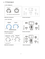
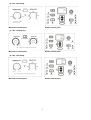
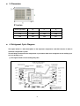
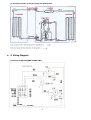
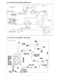
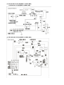
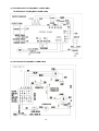
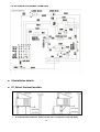
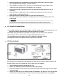
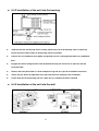
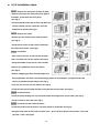
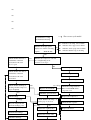
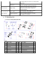
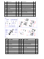
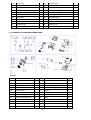
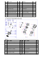
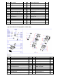
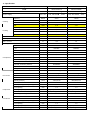
WC1E-1026-A
SERVICE MANUAL
MIDEA AIRCONDITIONER
Side Air Discharge Type
Factory No.
Sale No.
FR-KC26/N1-EE1(B4)
MWH-09CMN1-QB4
FR-KC26/N1Y-EE1(B4)
MWH-09CRN1-QB4
FR-KCR26/N1-EE1(B4)
MWH-09HMN1-QB4
FR-KCR26/N1Y-EE1(B4)
MWH-09HRN1-QB4
FR-KC35/N1-F1E1(B4)
MWF1-12CMN1-QB4
FR-KC35/N1Y-F1E1(B4)
MWF1-12CRN1-QB4
FR-KCR35/N1-F1E1(B4)
MWF1-12HMN1-QB4
FR-KCR35/N1Y-F1E1(B4)
MWF1-12HRN1-QB4
CE-KC46/N1-FE1(B4)
MWF-16CMN1-QB4
CE-KC46/N1Y-FE1(B4)
MWF-16CRN1-QB4
CE-KCR46/N1-FE1(B4)
MWF-16HMN1-QB4
CE-KCR46/N1Y-FE1(B4)
MWF-16HRN1-QB4
CONTENTS
1. Precaution .................................................................................................................................................... 1
1.1 Safety Precaution.......................................................................................................................... 1
1.2 Warning ......................................................................................................................................... 1
2. Function and control panel..................................................................... Fout! Bladwijzer niet gedefinieerd.
2.1 Function ........................................................................................Fout! Bladwijzer niet gedefinieerd.
2.2 Control panel ........................................................................................................................................ 6
3. Dimension .................................................................................................................................................... 8
4. Refrigerant Cycle Diagram ......................................................................................................................... 8
5. Wiring Diagram ............................................................................................................................................ 9
6. Installation details...................................................................................................................................... 14
6.1 Select the best location............................................................................................................... 14
6.2 Check off installation................................................................................................................... 15
6.3 How to drain ................................................................................................................................ 15
6.4 How to install............................................................................................................................... 16
6.4.1 Installation of the housing. ....................................................................................................... 16
6.4.2 Installation of the unit into the housing. ............................ Fout! Bladwijzer niet gedefinieerd.
6.4.3 Installation of the unit into the wall.................................... Fout! Bladwijzer niet gedefinieerd.
6.4.4 Installation steps ...................................................................................................................... 18
7. Operation characteristics ......................................................................................................................... 19
7.1 Cooling Operation ........................................................................................................................... 19
7.2 Heating Operation ........................................................................................................................... 19
7.3 Characteristic of temperature sensor.. .............................................................................................. 20
8. Protection Function................................................................................................................................... 21
8.1 Proper symbols and their meaning ............................................................................................. 21
8.2 Protection Function ..................................................................................................................... 21
8.2.1 Three minutes delay at restart for compressor........................................................................ 21
8.2.2 Anti-freezing protection at cooling or dry mode. ...................................................................... 21
8.2.3 Anti-frosting protection and defect at cooling or dry mode. ..................................................... 22
8.2.4 Auto-defrosting function in heating mode.. .............................................................................. 22
8.2.5 Temperature sensor is open circuit or short circuit.................................................................. 22
9. Troubleshooting......................................................................................................................................... 23
10. Exploding view ........................................................................................................................................ 32
11. Specification ……………………………………………………………………………………………
1. Precaution
1.1 Safety Precaution.
To prevent injury to the user or other people and property damage, the following instructions must
be followed.
Incorrect operation due to ignoring instruction will cause harm or damage.
Before service unit, be sure to read this service manual at first.
1.2 Warning.
Installation
Do not use a defective or underrated circuit breaker. Use this appliance on a dedicated circuit.
There is risk of fire or electric shock.
For electrical work, contact the dealer, seller, a qualified electrician, or an Authorized service center.
Do not disassemble or repair the product, there is risk of fire or electric shock.
Always ground the product.
There is risk of fire or electric shock.
Install the panel and the cover of control box securely.
There is risk of fire of electric shock.
Always install a dedicated circuit and breaker.
Improper wiring or installation may cause fore or electric shock.
Use the correctly rated breaker of fuse.
There is risk of fire or electric shock.
Do not modify or extend the power cable.
There is risk of fire or electric shock.
Do not install, remove, or reinstall the unit by yourself(customer).
There is risk of fire, electric shock, explosion, or injury.
Be caution when unpacking and installing the product.
Sharp edges could cause injury, be especially careful of the case edges and the fins on the condenser
and evaporator.
For installation, always contact the dealer or an Authorized service center.
1
There is risk of fire, electric shock, explosion, or injury.
Do not install the product on a defective installation stand.
It may cause injury, accident, or damage to the product.
Be sure the installation area does not deteriorate with age.
If the base collapses, the air conditioner could fall with it, causing property damage, product failure, and
personal injury.
Do not let the air conditioner run for a long time when the humidity is very high and a door or a
window is left open.
Moisture may condense and wet or damage furniture.
Take care to ensure that power cable could not be pulled out or damaged during operation.
There is risk of fire or electric shock.
Do not place anything on the power cable.
There is risk of fire or electric shock.
Do not plug or unplug the power supply plug during operation.
There is risk of fire or electric shock.
Do not touch (operation) the product with wet hands.
There is risk of fire or electric shock.
Do not place a heater or other appliance near the power cable.
There is risk of fire and electric shock.
Do not allow water to run into electric parts.
It may cause fire, failure of the product, or electric shock.
Do not store or use flammable gas or combustible near the product.
There is risk of fire or failure of product.
Do not use the product in a tightly closed space for a long time.
Oxygen deficiency could occur.
When flammable gas leaks, turn off the gas and open a window for ventilation before turn the
product on.
Do not use the telephone or turn switches on or off. There is risk of explosion or fire.
If strange sounds, or small or smoke comes from product. Turn the breaker off or disconnect the
power supply cable.
There is risk of electric shock or fire.
Stop operation and close the window in storm or hurricane. If possible, remove the product from the
2
window before the hurricane arrives.
There is risk of property damage, failure of product, or electric shock.
Do not open the inlet grill of the product during operation. (Do not touch the electrostatic filter, if the
unit is so equipped.)
There is risk of physical injury, electric shock, or product failure.
When the product is soaked (flooded or submerged), contact an Authorized service center.
There is risk of fire or electric shock.
Be caution that water could not enter the product.
There is risk of fire, electric shock, or product damage.
Ventilate the product from time to time when operating it together with a stove, etc.
There is risk of fire or electric shock.
Turn the main power off when cleaning or maintaining the product.
There is risk of electric shock.
When the product is not be used for a long time, disconnect the power supply plug or turn off the
breaker.
There is risk of product damage or failure, or unintended operation.
Take care to ensure that nobody could step on or fall onto the outdoor unit.
This could result in personal injury and product damage.
CAUTION.
Always check for gas (refrigerant) leakage after installation or repair of product.
Low refrigerant levels may cause failure of product.
Install the drain hose to ensure that water is drained away properly.
A bad connection may cause water leakage.
Keep level even when installing the product.
To avoid vibration of water leakage.
Do not install the product where the noise or hot air from the outdoor unit could damage the
neighborhoods.
It may cause a problem for your neighbors.
Use two or more people to lift and transport the product.
Avoid personal injury.
Do not install the product where it will be exposed to sea wind (salt spray) directly.
3
It may cause corrosion on the product. Corrosion, particularly on the condenser and evaporator fins,
could cause product malfunction or inefficient operation.
Operational.
Do not expose the skin directly to cool air for long periods of time. (Do not sit in the draft).
This could harm to your health.
Do not use the product for special purposes, such as preserving foods, works of art, etc. It is a
consumer air conditioner, not a precision refrigerant system
There is risk of damage or loss of property.
Do not block the inlet or outlet of air flow.
It may cause product failure.
Use a soft cloth to clean. Do not use harsh detergents, solvents, etc.
There is risk of fire, electric shock, or damage to the plastic parts of the product.
Do not touch the metal parts of the product when removing the air filter. They are very sharp.
There is risk of personal injury.
Do not step on pr put anything on the product. (outdoor units)
There is risk of personal injury and failure of product.
Always insert the filter securely. Clean the filter every two weeks or more often if necessary.
A dirty filter reduces the efficiency of the air conditioner and could cause product malfunction or damage.
Do not insert hands or other object through air inlet or outlet while the product is operated.
There are sharp and moving parts that could cause personal injury.
Do not drink the water drained from the product.
It is not sanitary could cause serious health issues.
Use a firm stool or ladder when cleaning or maintaining the product.
Be careful and avoid personal injury.
Replace the all batteries in the remote control with new ones of the same type. Do not mix old and
new batteries or different types of batteries.
There is risk of fire or explosion.
Do not recharge or disassemble the batteries. Do not dispose of batteries in a fire.
They may burn of explode.
4
If the liquid from the batteries gets onto your skin or clothes, wash it well with clean water. Do not
use the remote of the batteries have leaked.
The chemical in batteries could cause burns or other health hazards.
2. Function and control panel.
2.1 Function.
Powerful cooling and heating(heat pump and cooling).
Optional mode:dry and auto.
Slide-in and slide-out chassis for the simple installation and service.
Side air-intake, side cooled-air discharge.
Washable one-touch filter and easy removed panel.
Super compact design.
Reliable and efficient rotary compressor is equipped.
Unique Quiet Design.
Fresh air switch.
Sleep mode.
Swing function for some models.
Auto-on time setting and cancel.
Anti-freezing control in cooling mode. Prevent the water being freezed on evaporator by sensing the
evaporator pipe temperature in cooling mode.
Time Delay Safety. Restarting is for approx. 3 minutes.
Auto-restart, When the power supply is interrupted and then restore, the air conditioners
automatically restore the previous function setting.
Auto defrosting for cooling/heating products.
5
2.2 Control panel.
(1). 9K…Cooling only
Mechanical control panel
Remote control panel
(2). 9K…Heat Pump
Mechanical control panel
Remote control panel
(3). 12K…Cooling only
Mechanical control panel
Remote control panel
6
(4). 12K…Heat Pump
Mechanical control panel
Remote control panel
(5). 16K…Cooling only
Mechanical control panel
Remote control panel
(6). 16K…Heat Pump
Mechanical control panel
Remote control panel
7
3. Dimension.
E1 series
Dimension Mode
W
H
D
9K
450
346
535
12K
600
380
560
16K
660
430
687
4. Refrigerant Cycle Diagram.
The figure below is a brief description of the important components and their function in what is
called the refrigeration system.
This will help to understand the refrigeration cycle and the flow of the refrigerant in the cooling cycle
or in the heating cycle.
(1).This figure below is fit for Cooling Only Unit.
8
(2).This figure below is fit for Heat Pump and Cooling Unit.
5. Wiring Diagram.
(1).FR-KC26/N1-EE1(B4)(MWH-09CMN1-QB4)
9
(2). FR-KC26/N1Y-EE1(B4)(MWH-09CRN1-QB4)
(3). FR-KCR26/N1-EE1(B4)(MWH-09HMN1-QB4)
10
(4). FR-KCR26/N1Y-EE1(B4)(MWH-09HRN1-QB4)
(5). FR-KC35/N1-F1E1(B4)(MWF1-12CMN1-QB4)
11
(6). FR-KC35/N1Y-F1E1(B4)(MWF1-12CRN1-QB4)
CE-KC46/N1Y-FE1(B4)(MWF-16CRN1-QB4)
(7). FR-KCR35/N1-F1E1(B4)(MWF1-12HMN1-QB4)
12
(8). FR-KCR35/N1Y-F1E1(B4)(MWF1-12HRN1-QB4),
CE-KCR46/N1Y-FE1(B4)(MWF-16HRN1-QB4)
(9). CE-KC46/N1-FE1(B4)(MWF-16CMN1-QB4)
13
(10). CE-KCR46/N1-FE1(B4)(MWF-16HMN1-QB4)
6 Installation details.
6.1 Select the best location.
1. To avoid vibration and noise, make sure the unit is installed securely and firmly.
14
2. Install the unit where the sunlight does not shine directly on the unit. If the unit receives.
direct sunlight, build an awning to shade the cabinet.
3. There should be no obstacle, such as a fence or wall, within 50cm from the back of the
ambient because it will prevent heat radiation of the condenser.
4. Restriction of outside air will greatly reduce the cooling and heating efficiency of the air
conditioner.
5. Install the unit on a slight angle so that an condensate formed will not enter the room
(about 10mm or 1/4 bubble with level).
6. Install the unit with its bottom portion 75~150cm above the floor level.
7. The power cord must be connected to an independent circuit. The yellow/green wire must
be grounded.
6.2 Check off installation.
The setting conditions must be checked prior to initial starting. The under mentioned items are
especially important checking points when the installation is finished.
Grounding wire (yellow/Green) is provided in the power cord. The wire must be grounded.
Ensure that the unit is connected to a suitably rated and dedicated circuit.
To avoid vibration or noise, make sure the air conditioner is installed securely.
Avoid placing furniture of draperies in front of the air inlet and outlet.
6.3 How to drain.
The base pan may overflow due to high humidity. To drain the excess water, remove the drain cap
from the bottom of the unit (if fitted) and attach a drain hose (not supplied).
1. Take the drain pan which is packed with the unit.
2. Remove the rubber plug from the bottom of the base pan (if fitted).
3. Install the drain pan over the area of the cabinet where you removed the plug, and secure with 2
screws provided.
4. Connect the drain hose to the outlet located at the bottom of the drain pan. You can purchase
the drain hose or tubing locally to satisfy our particular needs (Drain hose is not supplied).
15
6.4 How to install.
6.4.1 Installation of the housing.
Step1
.Remove the air conditioner from it's packaging, remove fixing screws and slide the air conditioner
out of it's housing (Refer to Installation Steps)
Step2
.Prepare the hole in the wall so that the bottom of the housing is well supported, the top has
minimum clearance and the air inlet louvers have clearance as shown below in options A and B
(see below6.4.3). Holes from the outside through to the cavity should be sealed. The housing should
slope down towards the rear by about 5mm to allow water formed during operation to drain.
Step3
.Install the housing into the wall and secure. Ensure the foam seals are not damaged. Flash, seal or
fill gaps around the inside and outside to provide satisfactory appearance and protection against the
weather, insects and rodents.
16
6.4.2 Installation of the unit into the housing.
Slide the unit into the housing until it is firmly against the rear of the housing. Care is required to
ensure the foam sealing strips on the housing remain in position.
Connect the air conditioner to the power and position excess cord length beneath the air conditioner
base.
Engage the chassis fixing brackets into the bottom housing rail and secure to the base with the
screw provided.
Remove the front panel from it's carton and plastic bag and fit as per the installation instruction.
Switch unit on. Check for operation of the unit and check for vibration in the installation.
Fit the drain pan to the housing and run a drain line to a suitable location if required.
6.4.3 Installation of the unit into the wall.
17
6.4.4 Installation steps.
Step 1. Remove the front panel and the air filter.
.Hold the slot under the front panel, then uplift it
outwards, and remove the front panel
(See Fig.1).
.Pinch the handle under the air filter and make the
air filter arched, remove it from the slot from
underside to upside (See Fig.2).
Step 2. Remove the frame.
.Remove the two fixing screws from the frame
(See Fig.3).
.Grasp the left corner of the frame's underside,
then loosen the frame. (See Fig.4).
Step 3. Installation.
.Then remove the four screws located on both
sides and back sides of the cabinet.(See Fig.5).
.Grasp the handle on the chassis and carefully
slide the air conditioner out of the cabinet
(See Fig.6).
.Remove shipping pad from around compressor
before operation and make sure the discharge points to the drain pan are aligned before the
chassis is pushed into the cabinet (See Fig.7).
.Push the unit chassis into the cabinet (See Fig.8).
.Install the two chassis fixing brackets using the two fixing screws (See Fig.5).
Step 4. Install the frame.
.Install the frame making sure not to interfere with the temperature sensor cable (See Fig.9).
.Fix the screws on the frame (See Fig.3).
Step 5. Install the air filter and front panel.
.Install the air filter into the frame's slot from upside to underside (See Fig.2).
.Hang the front panel on the frame's buckle, then
you hear a click (See Fig10).
18
press the front panel into the frame's slot until
7 Operation characteristics.
7.1 Cooling operation.
℃ DB
Outdoor air temp.
Indndoor air temp.
℃ DB
7.2 Heating operation.
℃ DB
Indoor air temp.
℃ DB
Outdoor air temp.
19
7.3 Characteristic of temperature sensor.
℃
℃
℃
Temp.
Resistance KΩ
Temp.
Resistance KΩ
Temp.
Resistance KΩ
-10
62.2756
17
14.6181
44
4.3874
-9
58.7079
18
13.918
45
4.2126
-8
56.3694
19
13.2631
46
4.0459
-7
52.2438
20
12.6431
47
3.8867
-6
49.3161
21
12.0561
48
3.7348
-5
46.5725
22
11.5
49
3.5896
-4
44
23
10.9731
50
3.451
-3
41.5878
24
10.4736
51
3.3185
-2
39.8239
25
10
52
3.1918
-1
37.1988
26
9.5507
53
3.0707
0
35.2024
27
9.1245
54
2.959
1
33.3269
28
8.7198
55
2.8442
2
31.5635
29
8.3357
56
2.7382
3
29.9058
30
7.9708
57
2.6368
4
28.3459
31
7.6241
58
2.5397
5
26.8778
32
7.2946
59
2.4468
6
25.4954
33
6.9814
60
2.3577
7
24.1932
34
6.6835
61
2.2725
8
22.5662
35
6.4002
62
2.1907
9
21.8094
36
6.1306
63
2.1124
10
20.7184
37
5.8736
64
2.0373
11
19.6891
38
5.6296
65
1.9653
12
18.7177
39
5.3969
66
1.8963
13
17.8005
40
5.1752
67
1.830
14
16.9341
41
4.9639
68
1.7665
15
16.1156
42
4.7625
69
1.7055
16
15.3418
43
4.5705
70
1.6469
20
8. Protection Function.
8.1 Proper symbols and their meaning.
* T1: Indoor ambient temperature.
*.T2: Indoor evaporator temperature.
*.T3: Outdoor condenser temperature.
*.Ts: Setting temperature through the remote controller.
8.2 Protection Function.
8.2.1 Three minutes delay at restart for compressor.
8.2.2 Anti-freezing protection at cooling or dry mode.
(1).Anti-freezing control according to T2 (Indoor evaporator temperature).
℃ for 14 minutes, the evaporator
If the evaporator pipe temperature had been lower than 1
anti-freezing protection will be activated. The compressor will keep off in the following 5
minutes.
℃, the compressor will
5 minutes later, if the evaporator pipe temperature is still lower than 1
℃, the compressor will be started and the
stay off. If the temperature gets higher than 1
function is cancelled.
(2).Anti-freezing control according to TIME.
If the lasting time of compressor which is continuously running has got to 105 minutes with
fan motor operating under Med or Low speed and the indoor ambient temperature lower than
℃, the anti-freezing function will be activated. The compressor will keep off for 3 minutes
26
.
(3).Note:
If the compressor stops operation, the time will be cleared.
℃, the time
If the fan motor turns to High speed or the indoor ambient temperature gets over 26
will keep inactive, not be cleared.
21
8.2.3 Anti-frosting protection and defect at cooling or dry mode.
℃ for subsequent 3 minutes,
.3 minutes later when compressor is running, if T2 has been less than -15
the anti-frosting protection is activated and compressor will stop in the following 6 minutes.
.After that, if the condition for defrosting function is met again in the following 10 minutes while the
compressor is operating, the unit will display ‘Ed’ to indicate that the unit is in the defrost defect. The
compressor and fan motor will be OFF.
Note:The Defect display can be cancelled only by pressing the ON/OFF button on the unit or
the remote controller.
8.2.4 Auto-defrosting function in heating mode.
℃ for 40 minutes, the function will be
.If T3 (condenser pipe temperature) has been lower than 0
activated.
.The compressor will be ON while reverse valve and fan motor are OFF.
℃) or the defrosting time gets to 10 minutes,the
.If T3 (condenser pipe temperature gets over 20
function will be cancelled.
.After that, the compressor will shut down immediately with the fan motor starts.35 seconds later, the
reverse valve will be ON and the compressor will be ON after another 3 seconds.
8.2.5 Temperature sensor is open circuit or short circuit.
22
9 Troubleshooting.
In general, possible trouble is classified in three kinds. One is called Starting Failure which is
caused from an electrical defect, another is ineffective Air Conditioning caused by a defect in the
refrigeration circuit and improper application, and the other is called the Structure Damage.
Operation panel don't work.
Check the power supply.
No
Press the "LED" button of remote controller several times and
check whether the problem is settled down.
No
Defect code
Defect explanation
Yes
ambient
temperature sensor failure.
Er the wiringIndoor
Check
of display
board.
Repair the wiring.
No
En
Evaporator pipe temperature sensor failure.
Condenser pipe temperature sensor failure.
Eo
Replace the display board.
Evaporator de-frosting defect.
Ed
No
Replace the main control board.
Fan motor speed can’t change.
Check the wiring.
23
Check the capacitor of fan motor. Replace if failed.
No
No
No
Display keeps showing "Ed".
Check whether the evaporator frosts.
No
Check whether the indoor air inlet is blocked.
No
Check whether the indoor ambient temperature is too low.
No
Check whether the indoor dust filter is too dirty.
No
Check whether there is too much water on the chassis.
No
Check the wiring of pipe temperature sensor.
No
Yes
Check the pipe temperature sensor.
Replace the pipe temperature sensor.
No
Replace the main control board.
24
Compressor doesn’t work.
Check whether the indoor temperature is lower than 15°C or larger than 31
No
Check the power supply.
No
Check whether the voltage is too high or too low.
No
Check the wiring.
No
Check whether the compressor is under overload protection.
No
Check whether the relay of compressor in PCB works normally (Start the unit, after 3mins, and
set the unit with cool mode and 17°C (62°F). Then check the output of relay and replace the
PCB if failed.
No
Check whether the external
protector works normally.
Yes
Remove the overload protector and cool to
normal temperature. Then check whether it is
open circuit. Replace if failed.
No
Comparing with compressor specification, check the resistance of compressor.
No
Replace the compressor.
25
Cooling mode don't work or cooling not enough.
Check the operation mode.
No
Check the setting temperature.
No
Check whether dust filter is too dirty.
No
Start the unit with cool mode and check whether the
temperature of compressor’s discharge pipe is smaller than 90
. If no, recharge refrigerant.
℃
No
Replace the capillary.
The air-con doesn’t work.
Check the power supply.
No
Check the wiring.
No
26
Check whether the transformer is failed. Measure the output voltage of transformer and
check whether it is the range from +5V to 12V. If not, replace the transformer.
The compressor operates run-stop frequently.
Check whether the airflow passage is blocked.
No
Check whether the fan motor doesn’t work.
No
Check whether capacitor of compressor work normally.
No
Check whether the relay of compressor on PCB works normally.
No
Replace the PCB.
No
Check whether the capillary is blocked.
No
Replace the capillary.
No
Replace the compressor.
Water drips from the unit.
Check whether the ambient humidity is too high.
No
27
Check whether the indoor outlet airflow foam is too wet, and louver drip.
Check whether the unit is correctly installed.
No
No
No
No
:For reverse cycle model
No/ineffective cooling
No/ineffective heating
Whether the display panel
display one of the foollowing
signal?
"Er En Eo Ed"
Er…indicates room temp. sensor failure
En indicates indoor pipe sensor failure
Yes
Eo indicates outdoor pipe sensor failure
Ed indicates that the evap. Is frosting
NO
Check whether the indoor
outlet/inlet of the unit
is blocked or the vent
door is open
Yes
Whether the compressor can start
in cooling/heating mode
even if it soon stops?
NO
Check whether the outdoor
outlet/inlet of the unit
is blocked or the vent
is blocked
Check temperature. setting
Check wiring
Check compressor capacitor
Check whether the Evap.is
frosting and the compressor
stops frequently
No voltage
NO
Replace the main PCB
Yes
Check the speed of motor
Normal
Check leakage
leakage
Recycle refrigerant and
braze the leakage point
Check whether the temp. of
suction pipe is above 7
℃
In cooling
Replace the compressor
Check the fan capacitor
Yes
Replace the capillary tube
28
Vacuum and recharge
Replace the reverse valve
Check the drainage
Check the voltage between
RY9 on main PCB and N
on power cord
Replace the motor
PROBLEM
POSSIBLE CAUSE
No power
Power supply cord
Wire disconnected or
connection loose
Fan motor will not
run.
REMARK
Check voltage at electrical outlet.
Correct if none.
Check voltage at the power cord terminal.
Replace the power cord if none.
Connect wire. Refer to wiring diagram
for terminal identification.
Repair or replace loose terminal.
Main switch failure
Capacitor (Discharge
capacitor before testing)
Check and replace the main switch if failure.
Test capacitor.
Replace if not within +/-10% of manufacture's rating.
Replace if shorted, open or damaged.
Fan blade hitting shroud or blower hitting scroll.
Will not rotate
Check fan motor bearings. Replace the motor
if motor shaft do not rotate. Realign assembly.
Check voltage. Call an electrician if not within limits.
Test capacitor.
Fan motor runs
intermittently
Replace if not within +/-10% of manufacture's rating.
Cycles on overload.
Check bearings. Replace the motor if the fan
blade cannot rotate freely.
Pay attention to any change from high speed to low speed.
Replace the motor if the speed does not change.
Fan motor noise
Fan
Blower
Replace the fan if cracked, out of balance,
or partially missing.
Replace the blower if cracked, out of balance,
or partially missing.
29
Loose screws
Tighten them.
Replace the motor if knocking sounds continue
Worn bearings
when running or loose, or the motor hums or noise
appears
to be internal while running.
The compressor not
to stop even the room
temperature has got
to the setting
temperature.
Thermostat
Check and replace if the thermostat is damaged.
PROBLEM
POSSIBLE CAUSE
REMARK
Insufficient cooling or
heating.
Air filter
Clean or replace if restricted.
Vent door
Close if open.
Unit undersized
Determine if the unit is properly sized for
the area to be cooled or heated.
Condenser and Evaporator Clean or replace if restricted.
Fan motor
Room structure
Air flow
Sunlight
Check the fan capacitor and replace
if not within +/-10% of manufactures rating.
Take proper measures to make the door and windows
sealed well if gap is found.
Clean or remove if any barrier is found to
block the inlet/outlet wind flow of the unit.
Add a awning if the condenser is exposed to the sunlight.
Check the tubes for reasons of leakage.
Less refrigerant
Recycle the refrigerant,
correct the leakage points and recharge.
Regulate the flow if capillary tube and make
Capillary tube
the evaporating temperature appropriate if the evaporator
is frosted. Replace if blocked. Repair joint if leaking.
The inlet and outlet valve of the compressor is damaged,
making the low pressure connected with the high pressure.
Compressor
The refrigerating system can not produce high pressure
and low pressure. Replace the compressor after
checking for the reason.
Heat sources
Reduce if too many.
reverse valve
The seal in valve is damaged, making the low pressure
30
connected with the high pressure.
The refrigerating system can not produce high pressure
and low pressure. Replace the reverse valve
after checking for the reason.
The drainage is blocked.
Drainage
It will increase the efficiency in cooling mode,
but will cause the condenser to frost in heating mode.
PROBLEM
POSSIBLE CAUSE
REMARK
The amount of the refrigerant is too much,
Refrigerant
Stop instantly after
startup.
Recycle and recharge the refrigerant
after checking for the reason.
Compressor
No power
No cooling or heating.
making the compressor load too big.
The compressor is seized. Replace after
checking for the reason.
Check the voltage. Call an electrician
if no within the limit.
Wiring
Check the terminals. Repair and correct if loose.
Temperature setting
Check and adjust the thermostat.
Main switch setting
Check and adjust the main switch setting.
Reverse valve wire
Check the resistance of reverse valve wire.
Replace the wire if short, open or damaged.
If the reverse valve is blocked,
Reverse valve
the heating mode will not perform. Replace the reverse
valve after checking the reason.
Compressor will not
run while fan motor
runs.
Voltage
Check voltage. Call Supply Authority if not within limits.
Check the wire connections, if loose, repair
or replace the terminal. If wires are off,
Wiring
refer to wiring diagram for identification,
and replace. Check wire locations.
If not per wiring diagram, correct.
Main switch failure
Capacitor (Discharge
capacitor before testing)
Check and replace the main switch if failure.
Check the capacitor.
Replace if not within +/-10% of manufacturers rating.
Replace if shorted, open, or damaged.
Thermostat
Check the thermostat setting if not at the coolest
31
(in cooling mode) or the warmest (in heating mode).
Set it if not.
Check the compressor for open circuit or ground.
Compressor
If open or grounded, replace the compressor.
Remove the cabinet and carefully rearrange
Excessive noise.
Copper tubing
tubing not to contact cabinet, compressor,
shroud and barrier.
The input power supply voltage is too low.
Power supply
Call an electrician if not within limits.
The unit starts and
stops frequently.
When the outdoor temperature is too high,
Outdoor temperature
the compressor will protect.
10. Exploding view.
(1). FR-KC26/N1-EE1(B4)(MWH-09CMN1-QB4)
Part list:
No.
Part Name
Qty
No.
Part Name
Qty
1
Front panel assembly
1
14
Centrfugal fan
1
1.1
Front panel
1
15
Cover
1
1.2
Filter
1
16
Rear separating board
1
1.3
Front frame
1
17
Front separating board
1
1.4
Louver holder
1
18
Scroll
1
1.5
Horizontal louver
9
19
Vent door
1
1.6
Air out frame
1
20
Air leading board
1
1.7
Cover for Control panel
1
21
Seat
1
4
Knob
2
22
Guide seat
1
32
5
Control cover
1
23
Air-inlet board
1
7
E-Part box assembly
1
24
Evaporator base
1
7.11
E-Part box
1
25
Condensator
1
7.16
Capacitor clamp
1
26
Capillary assembly
1
7.17
Compressor capacitor
1
27
Evaporator
1
7.18
Main switch
1
28
Left retaining plate of chassis
1
7.21
Capacitor
1
29
Right retaining plate of chassis
1
7.22
Temperature controller
1
30
Suction pipe
1
7.23
Power cord
1
31
Discharge pipe
1
10
E-part box cover
1
33
Cabinet assembly
1
11
Propeller fan
1
35
Rubber
2
12
Holder for fan motor
1
36
Compressor
1
13
Fan motor
1
37
Chassis assembly
1
(2). FR-KC26/N1Y-EE1(B4)(MWH-09CRN1-QB4)
Part list:
No.
Part Name
Qty
No.
Part Name
Qty
1
Front panel assembly
1
13
Fan motor
1
1.1
Front panel
1
14
Centrfugal fan
1
1.2
Filter
1
15
Cover
1
1.3
Front frame
1
16
Rear separating board
1
1.4
Louver holder
1
17
Front separating board
1
1.5
Horizontal louver
9
18
Scroll
1
1.6
Air out frame
1
19
Vent door
1
2
Remote controller
1
20
Air leading board
1
3
Display box assembly
1
21
Seat
1
3.1
Control panel
1
22
Guide seat
1
6
Fixing board for E-parts box
1
23
Air-inlet board
1
7
E-Part box assembly
1
24
Evaporator base
1
33
7.11
E-Part box
1
25
Condensator
1
7.12
Indoor temperature sensor
1
26
Capillary assembly
1
7.13
Pipe temperature sensor
1
27
Evaporator
1
7.14
Transformer
1
28
Left retaining plate of chassis
1
7.17
Compressor capacitor
1
29
Right retaining plate of chassis
1
7.20
Main control board
1
30
Suction pipe
1
7.21
Capacitor
1
31
Discharge pipe
1
7.23
Power cord
1
33
Cabinet assembly
1
10
E-part box cover
1
35
Rubber
2
11
Propeller fan
1
36
Compressor
1
12
Holder for fan motor
1
37
Chassis assembly
1
(3). FR-KCR26/N1-EE1(B4)(MWH-09HMN1-QB4)
Part list:
No.
Part Name
Qty
No.
Part Name
Qty
1
Front panel assembly
1
14
Centrfugal fan
1
1.1
Front panel
1
15
Cover
1
1.2
Filter
1
16
Rear separating board
1
1.3
Front frame
1
17
Front separating board
1
1.4
Louver holder
1
18
Scroll
1
1.5
Horizontal louver
9
19
Vent door
1
1.6
Air out frame
1
20
Air leading board
1
1.7
Cover for Control panel
1
21
Seat
1
4
Knob
2
22
Guide seat
1
5
Control cover
1
23
Air-inlet board
1
7
E-Part box assembly
1
24
Evaporator base
1
7.11
E-Part box
1
25
Condensator
1
34
7.15
Wire joint
2
26
Capillary assembly
1
7.16
Capacitor clamp
1
27
Evaporator
1
7.17
Compressor capacitor
1
28
Left retaining plate of chassis
1
7.18
Main switch
1
29
Right retaining plate of chassis
1
7.21
Capacitor
1
32
Four-ways valve assembly
1
7.22
Temperature controller
1
33
Cabinet assembly
1
7.23
Power cord
1
34
Water drain pan
1
10
E-part box cover
1
35
Rubber
1
11
Propeller fan
1
36
Compressor
1
12
Holder for fan motor
1
37
Chassis assembly
1
13
Fan motor
1
/
/
/
(4). FR-KCR26/N1Y-EE1(B4)(MWH-09HRN1-QB4)
Part list:
No.
Part Name
Qty
No.
Part Name
Qty
1
Front panel assembly
1
13
Fan motor
1
1.1
Front panel
1
14
Centrfugal fan
1
1.2
Filter
1
15
Cover
1
1.3
Front frame
1
16
Rear separating board
1
1.4
Louver holder
1
17
Front separating board
1
1.5
Horizontal louver
9
18
Scroll
1
1.6
Air out frame
1
19
Vent door
1
2
Remote controller
1
20
Air leading board
1
3
Display box assembly
1
21
Seat
1
3.1
Control panel
1
22
Guide seat
1
6
Fixing board for E-parts box
1
23
Air-inlet board
1
7
E-Part box assembly
1
24
Evaporator base
1
35
7.11
E-Part box
1
25
Condensator
1
7.12
Indoor temperature sensor
1
26
Capillary assembly
1
7.13
Pipe temperature sensor
1
27
Evaporator
1
7.13
Pipe temperature sensor
1
28
Left retaining plate of chassis
1
7.14
Transformer
1
29
Right retaining plate of chassis
1
7.17
Compressor capacitor
1
32
Four-ways valve assembly
1
7.20
Main control board
1
33
Cabinet assembly
1
7.21
Capacitor
1
34
Water drain pan
1
7.23
Power cord
1
35
Rubber
1
10
E-part box cover
1
36
Compressor
1
11
Propeller fan
1
37
Chassis assembly
1
12
Holder for fan motor
1
/
/
/
(5). FR-KC35/N1-F1E1(B4)(MWF1-12CMN1-QB4)
Part list:
No.
Part Name
Qty
No.
Part Name
Qty
1
Front panel assembly
1
9
Capillary assembly
1
1.1
Front panel
1
10
Suction pipe
1
1.2
Filter
1
11
Compressor
1
1.3
Front frame
1
12
Discharge pipe
1
1.4
Air out frame
1
14
Condensor
1
1.5
Link, ventilation
1
15
Evaporator base
1
1.6
Horizontal louver II
9
16
Wind inlet guide
1
1.7
Control panel
1
17
Fan shell base
1
2
Control cover
1
18
Fan shell
1
3
Knob
2
19
Front board
1
6
E-Part box assembly
1
21
Buttstrap
1
6.11
E-Part box
1
22
Rear separating board
1
36
6.12
Compressor capacitor
1
23
Cabinet assembly
1
6.13
Capacitor clamp
1
25
Propeller fan
1
6.15
Swing motor
1
26
Fan motor
1
6.16
Temperature controller
1
27
Holder for fan motor
1
6.16
Temperature controller
1
29
Chassis assembly
1
6.19
Power cord assembly
1
30
Centrifugal fan
1
6.20
Main switch
1
31
Drain stopper
1
6.22
Capacitor
1
32
Air leading board
1
7
Side board of E-Part box
1
33
Vent door
1
8
Evaporator
1
/
/
/
(6). FR-KC35/N1Y-F1E1(B4)(MWF1-12CRN1-QB4)
Part list:
No.
Part Name
Qty
No.
Part Name
Qty
1
Front panel assembly
1
8
Evaporator
1
1.1
Front panel
1
9
Capillary assembly
1
1.2
Filter
1
10
Suction pipe
1
1.3
Front frame
1
11
Compressor
1
1.4
Air out frame
1
12
Discharge pipe
1
1.5
Link, ventilation
1
14
Condensor
1
1.6
Horizontal louver II
9
15
Evaporator base
1
2
Control cover
1
16
Wind inlet guide
1
4
Remote controller
1
17
Fan shell base
1
5
Display box assembly
1
18
Fan shell
1
5.1
Control panel
1
19
Front board
1
37
6
E-Part box assembly
1
21
Buttstrap
1
6.11
E-Part box
1
22
Rear separating board
1
6.12
Compressor capacitor
1
23
Cabinet assembly
1
6.13
Capacitor clamp
1
25
Propeller fan
1
6.15
Swing motor
1
26
Fan motor
1
6.17
Pipe temperature sensor
1
27
Holder for fan motor
1
6.18
Indoor temp sensor
1
29
Chassis assembly
1
6.19
Power cord assembly
1
30
Centrifugal fan
1
6.21
Main control board
1
31
Drain stopper
1
6.22
Capacitor
1
32
Air leading board
1
6.23
Transformer
1
33
Vent door
1
7
Side board of E-Part box
1
/
/
/
(7). FR-KCR35/N1-F1E1(B4)(MWF1-12HMN1-QB4)
Part list:
No.
Part Name
Qty
No.
Part Name
Qty
1
Front panel assembly
1
8
Evaporator
1
1.1
Front panel
1
9
Capillary assembly
1
1.2
Filter
1
11
Compressor
1
1.3
Front frame
1
13
Four-Way valve assembly
1
1.4
Air out frame
1
14
Condensor
1
1.5
Link, ventilation
1
15
Evaporator base
1
1.6
Horizontal louver II
9
16
Wind inlet guide
1
1.7
Control panel
1
17
Fan shell base
1
2
Control cover
1
18
Fan shell
1
3
Knob
2
19
Front board
1
6
E-Part box assembly
1
21
Buttstrap
1
38
6.11
E-Part box
1
22
Rear separating board
1
6.12
Compressor capacitor
1
23
Cabinet assembly
1
6.13
Capacitor clamp
1
24
water drain pan
1
6.14
Wire joint
1
25
Propeller fan
1
6.15
Swing motor
1
26
Fan motor
1
6.16
Temperature controller
1
27
Holder for fan motor
1
6.16
Temperature controller
1
29
Chassis assembly
1
6.16
Temperature controller
1
30
Centrifugal fan
1
6.19
Power cord assembly
1
31
Drain stopper
1
6.20
Main switch
1
32
Air leading board
1
6.22
Capacitor
1
33
Vent door
1
7
Side board of E-Part box
1
/
/
/
(8). FR-KCR35/N1Y-F1E1(B4)(MWF1-12HRN1-QB4)
Part list:
No.
Part Name
Qty
No.
Part Name
Qty
1
Front panel assembly
1
8
Evaporator
1
1.1
Front panel
1
9
Capillary assembly
1
1.2
Filter
1
11
Compressor
1
1.3
Front frame
1
13
Four-Way valve assembly
1
1.4
Air out frame
1
14
Condensor
1
1.5
Link, ventilation
1
15
Evaporator base
1
1.6
Horizontal louver II
9
16
Wind inlet guide
1
2
Control cover
1
17
Fan shell base
1
4
Remote controller
1
18
Fan shell
1
5
Display box assembly
1
19
Front board
1
5.1
Control panel
1
21
Buttstrap
1
39
6
E-Part box assembly
1
22
Rear separating board
1
6.11
E-Part box
1
23
Cabinet assembly
1
6.12
Compressor capacitor
1
24
water drain pan
1
6.13
Capacitor clamp
1
25
Propeller fan
1
6.15
Swing motor
1
26
Fan motor
1
6.17
Pipe temperature sensor
1
27
Holder for fan motor
1
6.18
Indoor temp sensor
1
29
Chassis assembly
1
6.19
Power cord assembly
1
30
Centrifugal fan
1
6.21
Main control board
1
31
Drain stopper
1
6.22
Capacitor
1
32
Air leading board
1
6.23
Transformer
1
33
Vent door
1
7
Side board of E-Part box
1
/
/
/
(9). CE-KC46/N1-FE1(B4)(MWF-16CMN1-QB4)
Part list:
No.
Part Name
Qty
No.
Part Name
Qty
1
Front panel assembly
1
10
Centrifugal fan
1
1.1
Front panel
1
11
Vent door
1
1.2
Filter
1
12
Link, ventilation
1
1.3
Front frame
1
13
Air leading board
1
1.4
Louver holder
1
14
Wind inlet guide
1
1.5
Horizontal louver
10
15
Fan shell base
1
1.6
Air out frame assembly
1
16
Fan shell
1
1.7
Cover of front panel
1
17
Evaporator base
1
3
E-Part box assembly
1
18
Front cover
1
3.11
E-Part box
1
19
Front separating board
1
3.12
Swing motor
1
20
Connecting board
1
40
3.13
Main switch
1
21
Buttstrap
1
3.14
Temperature controller
1
22
Rear separating board
1
3.14
Temperature controller
1
24
Rear cover
1
3.15
Capacitor
1
25
Cabinet assembly
1
3.22
Power cord assembly
1
28
Condensor
1
3.23
Compressor capacitor
1
29
Discharge pipe
1
3.24
Capacitor clamp
1
30
Suction pipe
1
4
Control cover
1
32
Drain stopper
1
5
Knob
2
33
Compressor
1
6
Side board of E-Part box
1
34
Chassis assembly
1
7
Propeller fan
1
35
Capillary assembly
1
8
Fan motor
1
36
Evaporator
1
9
Holder for fan motor
1
/
/
/
(10). CE-KC46/N1Y-FE1(B4)(MWF-16CRN1-QB4)
Part list:
No.
Part Name
Qty
No.
Part Name
Qty
1
Front panel assembly
1
9
Holder for fan motor
1
1.1
Front panel
1
10
Centrifugal fan
1
1.2
Filter
1
11
Vent door
1
1.3
Front frame
1
12
Link, ventilation
1
1.4
Louver holder
1
13
Air leading board
1
1.5
Horizontal louver
10
14
Wind inlet guide
1
1.6
Air out frame assembly
1
15
Fan shell base
1
2
Display box assembly
1
16
Fan shell
1
2.1
Control panel
1
17
Evaporator base
1
3
E-Part box assembly
1
18
Front cover
1
3.11
E-Part box
1
19
Front separating board
1
41
3.12
Swing motor
1
20
Connecting board
1
3.15
Capacitor
1
21
Buttstrap
1
3.17
Main control board assembly
1
22
Rear separating board
1
3.18
Pipe temperature sensor assembly
1
24
Rear cover
1
3.19
Transformer
1
25
Cabinet assembly
1
3.20
Indoor temp sensor assembly
1
28
Condensor
1
3.21
Wire joint base
1
30
Suction pipe
1
3.22
Power cord assembly
1
32
Drain stopper
1
3.23
Compressor capacitor
1
33
Compressor
1
3.24
Capacitor clamp
1
34
Chassis assembly
1
4
Control cover
1
35
Capillary assembly
1
6
Side board of E-Part box
1
36
Evaporator
1
7
Propeller fan
1
37
Remote controller
1
8
Fan motor
1
/
/
/
(11). CE-KCR46/N1-FE1(B4)(MWF-16HMN1-QB4)
Part list:
No.
Part Name
Qty
No.
Part Name
Qty
1
Front panel assembly
1
9
Holder for fan motor
1
1.1
Front panel
1
10
Centrifugal fan
1
1.2
Filter
1
11
Vent door
1
1.3
Front frame
1
12
Link, ventilation
1
1.4
Louver holder
1
13
Air leading board
1
1.5
Horizontal louver
10
14
Wind inlet guide
1
1.6
Air out frame assembly
1
15
Fan shell base
1
1.7
Cover of front panel
1
16
Fan shell
1
3
E-Part box assembly
1
17
Evaporator base
1
3.11
E-Part box
1
18
Front cover
1
3.12
Swing motor
1
19
Front separating board
1
42
3.13
Main switch
1
20
Connecting board
1
3.14
Temperature controller
1
21
Buttstrap
1
3.14
Temperature controller
1
22
Rear separating board
1
3.14
Temperature controller
1
24
Rear cover
1
3.15
Capacitor
1
25
Cabinet assembly
1
3.22
Power cord assembly
1
26
water drain pan
1
3.23
Compressor capacitor
1
28
Condensor
1
3.24
Capacitor clamp
1
31
Four-Way valve assembly
1
3.25
Wire joint
2
32
Drain stopper
1
4
Control cover
1
33
Compressor
1
5
Knob
2
34
Chassis assembly
1
6
Side board of E-Part box
1
35
Capillary assembly
1
7
Propeller fan
1
36
Evaporator
1
8
Fan motor
1
/
/
/
(12). CE-KCR46/N1Y-FE1(B4)(MWF-16HRN1-QB4)
Part list:
No.
Part Name
Qty
No.
Part Name
Qty
1
Front panel assembly
1
9
Holder for fan motor
1
1.1
Front panel
1
10
Centrifugal fan
1
1.2
Filter
1
11
Vent door
1
1.3
Front frame
1
12
Link, ventilation
1
1.4
Louver holder
1
13
Air leading board
1
1.5
Horizontal louver
10
14
Wind inlet guide
1
1.6
Air out frame assembly
1
15
Fan shell base
1
2
Display box assembly
1
16
Fan shell
1
2.1
Control panel
1
17
Evaporator base
1
3
E-Part box assembly
1
18
Front cover
1
43
3.11
E-Part box
1
19
Front separating board
1
3.12
Swing motor
1
20
Connecting board
1
3.15
Capacitor
1
21
Buttstrap
1
3.17
Main control board assembly
1
22
Rear separating board
1
3.18
Pipe temperature sensor assembly
1
24
Rear cover
1
3.18
Pipe temperature sensor assembly
1
25
Cabinet assembly
1
3.19
Transformer
1
26
water drain pan
1
3.20
Indoor temp sensor assembly
1
28
Condensor
1
3.22
Power cord assembly
1
31
Four-Way valve assembly
1
3.23
Compressor capacitor
1
32
Drain stopper
1
3.24
Capacitor clamp
1
33
Compressor
1
4
Control cover
1
34
Chassis assembly
1
6
Side board of E-Part box
1
35
Capillary assembly
1
7
Propeller fan
1
36
Evaporator
1
8
Fan motor
1
37
Remote controller
1
44
11. Specification
Project
G110-C21
G110-C21
Code
220021403010
220021702880
Model
MWH-09CRN1-QB4
MWF1-12CRN1-QB4
Heating
~
1Ph, 220-240V , 50Hz
1Ph, 220-240V , 50Hz
Btu/h
9000
12000
Input
W
1100
1450
Rated current
A
4.8
6.5
EER
W/W
2.41
2.41
Capacity
Btu/h
N/A
N/A
Input
W
N/A
N/A
Rated current
A
N/A
N/A
W/W
N/A
N/A
1
1.2
Capacity
Cooling
~
Ph-V-Hz
Power supply
COP
Moisture Removal
L/h
Max. input consumption
W
1450
1800
Max. current
A
7.8
10
Starting current
A
21.7
26.7
Model
PA103M1C-4DZDE2
PA145G1C-4FT1
Type
ROTARY
ROTARY
Brand
TOSHIBA
TOSHIBA
Btu/h
8428/8530
12215/12334
Input
W
830/860
1240/1330
Rated current(RLA)
A
3.85/3.73
5.82/6.10
Locked rotor Amp(LRA)
A
21.7
26.7
B160-135-241E
----
EXTERNAL
INTERNAL
Capacity
Compressor
Thermal protector
Thermal protector position
Fan motor
Capacitor
uF
25
35
Refrigerant oil/oil charge
ml
ESTER OIL VG74 .350
ESTER OIL VG74/400
Model
YSK60-4C(S)
YSK40-6F
Brand
Welling
Welling
Input
W
112/84.5
99/85/78
Capacitor
uF
2.5
4
r/min
1270/1075
890/810/730
3
2
Speed(Hi/Mi/Lo)
a.Number of rows
Evaporator
Condenser
b.Tube pitch(a)x row pitch(b)
mm
21x13.37
21x13.37
c.Fin spacing
mm
1.2
1.3
Hydrophilic aluminium
Hydrophilic aluminium
d.Fin type (code)
e.Tube outside dia.and type
mm
Φ7,innergroove tube
Φ7,innergroove tube
f.Coil length x height x width
mm
248x294x40.11
355x336x26.74
g.Number of circuits
2
2
a.Number of rows
2
2
b.Tube pitch(a)x row pitch(b)
mm
19.5x11.6
19.5x11.6
c.Fin spacing
mm
1.3
1.2
UnHydrophilic aluminium
UnHydrophilic aluminium
Φ5,innergroove tube
Φ5,innergroove tube
d.Fin type (code)
e.Tube outside dia.and type
mm
45
f.Coil length x height x width
mm
g.Number of circuits
370x331.5x23.2
623x351x23.2
2
2
Indoor Air Flow Volume
m3/h
420/395/360
460/420/370
Indoor Noise Level(H/M/L) Sound Pressure Level
dB(A)
51/49/45
53/50/47
Indoor Noise Level(H/M/L) Sound Power Level
dB(A)
60/57/54
62/59/56
Outdoor Air Flow Volume
m3/h
785/720/650
970/865/760
Outdoor Noise Level(H/M/L) Sound Pressure Level
dB(A)
58/57/54
59/57/55
Outdoor Noise Level(H/M/L) Sound Power Level
dB(A)
67/66/63
68/66/64
Refrigerant type
g
R410A / 360
R410A / 480
Design pressure
MPa
4.2/1.5
4.2/1.5
1.0x3/VDE
1.5x3/VDE
Remote control
Remote control
17-30
17-30
Plug type
Thermostat type
Operation temp
℃
Application area
m2
14-20
18-26
Dimension(W*H*D)
mm
450x350x540
600x380x560
Packing
mm
495x435x580
685x430x620
Kg
29.5/32
36.5/41
220/480/575
135/285/340
(W*H*D)
Net/Gross weight
Qty’per 20’ /40’ /40'HQ
46
Project
G110-C21
Code
220021800960
Model
MWF-16CRN1-QB4
Power supply
1Ph, 220-240V , 50Hz
Btu/h
16000
Input
W
1950
Rated current
A
9
EER
W/W
2.41
Capacity
Btu/h
N/A
Input
W
N/A
Rated current
A
N/A
W/W
N/A
Capacity
Cooling
Heating
~
Ph-V-Hz
COP
Moisture Removal
L/h
1.6
Max. input consumption
W
2700
Max. current
A
15
Starting current
A
25.9
Model
PA185M2C-4FT2
Type
ROTARY
Brand
TOSHIBA
Capacity
Compressor
Btu/h
15252
Input
W
1500
Rated current(RLA)
A
7
Locked rotor Amp(LRA)
A
25.9
Thermal protector
----
Thermal protector position
Fan motor
INTERNAL
Capacitor
uF
35
Refrigerant oil/oil charge
ml
ESTER OIL VG74 480cc
Model
YSK90-6
Brand
Welling
Input
W
165/155/145
Capacitor
uF
6
r/min
770/690/620
Speed(Hi/Mi/Lo)
a.Number of rows
Evaporator
2
b.Tube pitch(a)x row pitch(b)
mm
21x13.37
c.Fin spacing
mm
1.3
d.Fin type (code)
Hydrophilic aluminium
e.Tube outside dia.and type
mm
Ф7, innergroove tube
f.Coil length x height x width
mm
390x378x26.74
g.Number of circuits
Condenser
4
a.Number of rows
1.5
b.Tube pitch(a)x row pitch(b)
mm
19.5x11.6
c.Fin spacing
mm
1.2
d.Fin type (code)
Unhydrophilic aluminium
e.Tube outside dia.and type
mm
47
Ф5, innergroove tube
f.Coil length x height x width
mm
g.Number of circuits
688x390x11.6+450x390x11.6
3
Indoor Air Flow Volume
m3/h
730/650/570
Indoor Noise Level(H/M/L) Sound Pressure Level
dB(A)
54/50/48
Indoor Noise Level(H/M/L) Sound Power Level
dB(A)
63/60/57
Outdoor Air Flow Volume
m3/h
1225/1100/970
Outdoor Noise Level(H/M/L) Sound Pressure Level
dB(A)
59/58/55
Outdoor Noise Level(H/M/L) Sound Power Level
dB(A)
68/67/64
Refrigerant type
g
R410A / 630
Design pressure
MPa
4.2/1.5
Plug type
2.5x3/---
Thermostat type
Remote control
Operation temp
℃
Application area
m2
21-35
Dimension(W*H*D)
mm
660x430x687
Packing
mm
746x515x815
Kg
49/53.5
(W*H*D)
Net/Gross weight
Qty’per 20’ /40’ /40'HQ
17-30
84/176/220
48