1
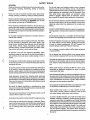
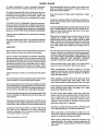
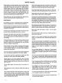
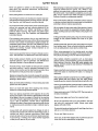
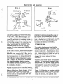
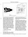
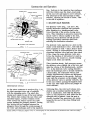
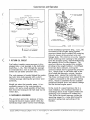
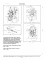
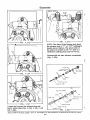
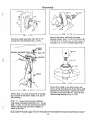
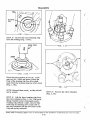
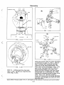
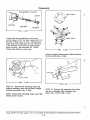
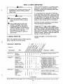
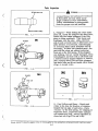
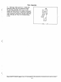
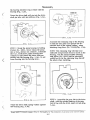
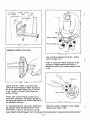
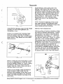
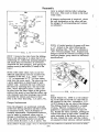
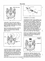
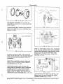
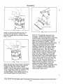
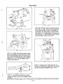
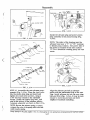
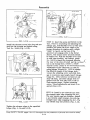
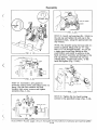
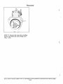
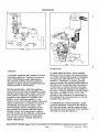
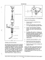
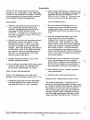
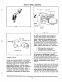
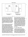
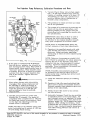
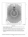
Reassembly
(shoes bottomed on the leaf spring) by the
air pressure . Using a 1" to 2" micrometer,
measure the roller-to-roller dimension
(Fig. 5.7c) (distance between the outer surfaces of the opposed cam rollers) and compare this with the specification. To set the
roller-to-roller dimension to the pump
specification, turn the leaf spring adjusting
screw inward (clockwise) to increase and
outward (counter-clockwise) to reduce the
roller-to-roller dimension.
NOTE: The roller-to-roller setting provides
a completely accurate maximum fuel adjustment and it should not differ from that
shown in the TEST STAND DATA ( Topic 9)
rotor assembly to the fixture on the air inlet side. Loosen the dial indicator retaining
screw and slide the indicator to its outer
limit . Rotate the rotor until the rollers are
pushed to their extreme outward position
(shoes bottomed on the leaf spring) by the
air pressure. Using a 1" to 2" micrometer,
measure the roller-to-roller dimensions
(Fig. 5.7d) (distance between the outer
surfaces of the opposed cam rollers) and
compare this with the specification. To set
the roller-to-roller dimension to the pump
specification, set the rollers, adjusting
each leaf spring alternately. Turn the leaf
spring adjusting screws inward (clockwise)
to increase and outward (counter-clockwise)
to reduce the roller-to-roller dimensions.
Since each roller shoe for a given cylinder
is controlled by a separate leaf spring, it
may be necessary to invert or interchange
leaf springs to obtain correct dimensions on
both sets of rollers. Roller settings of both
cylinders must be within .003" of each
other while maintaining the average rollerto-roller setting within the specification.
Check centrality of the rollers (to assure
that each one starts its pumping stroke at
the same time) as follows:
a.
Rotate the rotor until one roller is
aligned with the dial indicator plunger.
Slide the indicator inward until plunger
depresses it at least .010". Lock indicator retaining screw. "Zero" in indicator on high point of roller by rotating knurled dial.
b.
Rotate rotor (either direction) until the
next roller depresses dial indicator
plunger , Allowable centrality is plus
or minus .002" (total .004"). Before
making any correction, check and record centrality of all four rollers .
c.
If roller centrality is beyond specified
tolerance, rollers and/or shoes can be
interchanged. Recheck centrality after
each change. Be sure to recheck rollerto-roller dimension.
FIG. 5.7d
DM4
Install Fixture No. 19969 in a vise (clamping on the flat) so that the air inlet hole is
not covered by the vise . Assemble a 1/4"18 NPT fitting to the air inlet of the fixture .
This fitting should be adapted to a supply of
clean, filtered, compressed air regulated
to a pressure between 40 and 100 psi.
Handle the rotor carefully, holding the
rollers and shoes in their slots . Install the
NOTE: The roller-to-roller setting provides a completely accurate maximum fuel
adjustment and it should not differ from that
shown in the applicable specification.
Study SAFETY RULES, pages I thru Ill, thoroughly for the protection of personal and machine safety.
5-7