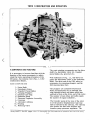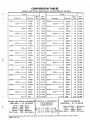
1
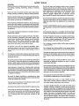
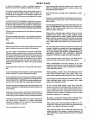
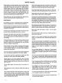
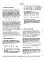
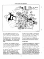
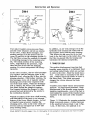
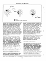
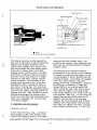
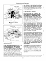
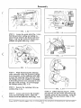
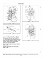
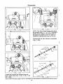
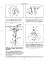
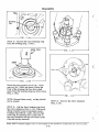
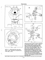
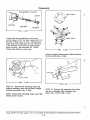
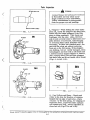
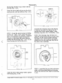
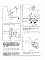
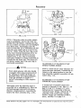
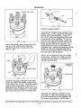
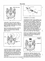
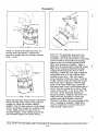
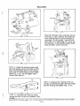
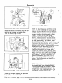
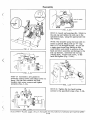
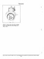
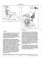
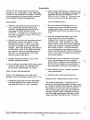
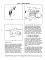
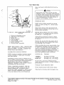
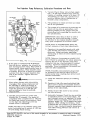
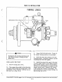
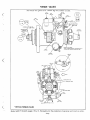
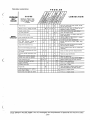
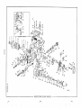
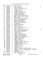
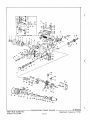
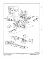
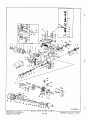
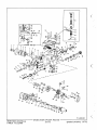
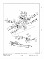
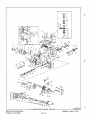
Accessories
off of the pump during an electrical failure
is accomplished by pulling out the override
rod.
3. Remove the snap ring and pull the control rod out of the guide.
4. Loosen and remove the cover guide, the
washer and the seal.
DISASSEMBLY
Remove the cover screws, governor control
cover and gasket from pump. Remove the
cover contact nuts and washers and work the
solenoid assembly out of the cover. Remove
the shut off spring and arm.
Some applications will incorporate a grounding wire assembly secured at one end to a
contact screw and at the other end to the
rear control cover screw in order to provide
a grounded connection. On these applications
a "hot" lead only is required for the opposite
terminal.
CHECKING ARMATURE TRAVEL
ENERGIZED TO RUN
ENERGIZED TO SHUT OFF
MECHANICAL OVERRIDE
FIG. 6.5
1. Remove the governor control cover.
2. Push in the control rod so that the snap
ring is away from the inside edge of the
guide assembly.
RING
as
eleea.
as
SEAL
ADJUSTING ARMATURE TRAVEL
L
ENERGIZED TO RUN
ENERGIZED TO SHUT OFF
GUIDE
ASSEMBLY
FIG. 6.6
WASHER
INSPECTION
Examine the solenoid visually for cracks
and swelling in the encapsulating material
and looseness of the contact screws. Check
the solenoid for a complete circuit with an
ohmmeter .
MECHANICAL OVERRIDE DEVICE
FIG. 6.4
Study SAFETY RULES, pages I thru III, thoroughly for the protection of personal and machine safety
6-2