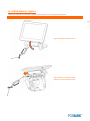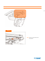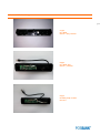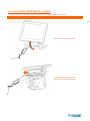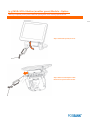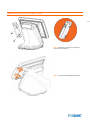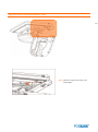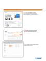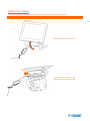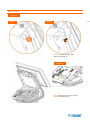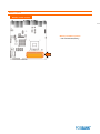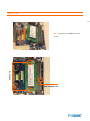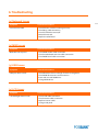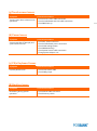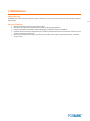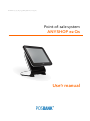
1
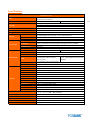
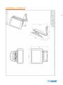
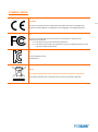
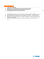
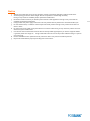
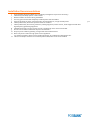
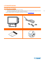
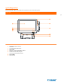
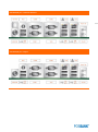
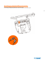
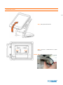
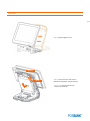
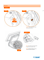
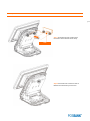
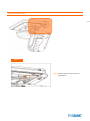
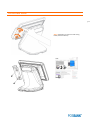
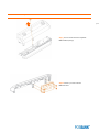
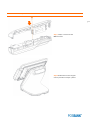
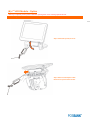
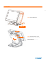
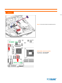
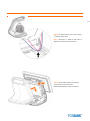
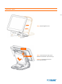
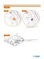
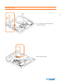
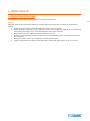
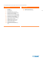
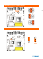
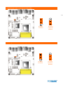
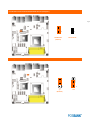
ANYSHOP e2_Qs_UM_eng_PBUM_E(Rev002;20140926) Point-of-sale system ANYSHOP e2 Qs Use’r manual -Table of ContentsPOSBANK USER’S MANUAL REVISION HISTORY ............................................................................................................................... 3 SPECIFICATION ............................................................................................................................................................................... 4 (1) SPECIFICATION - OUTSIDE SIZE ............................................................................................................................................. 5 PREFACE ......................................................................................................................................................................................... 6 SYMBOL; MARK .............................................................................................................................................................................. 7 COPYRIGHT..................................................................................................................................................................................... 8 WARRANTY ..................................................................................................................................................................................... 9 SAFETY INSTRUCTIONS................................................................................................................................................................ 10 NOTICE...........................................................................................................................................................................................11 LIABILITY LIMITATION .................................................................................................................................................................. 12 INSTALLATION RECOMMENDATIONS ...........................................................................................................................................13 1. PRODUCTOVERVIEW...................................................................................................................................................... 14 (1) INSIDE YOUR PACKAGE .............................................................................................................................................................................. 14 (2) PRE-INSTALLATION PREPARATION .............................................................................................................................................................15 (3) PRODUCT OUTLINE .................................................................................................................................................................................... 16 (4) CONFIGURATION ........................................................................................................................................................................................ 17 (5) I/O PORT: DETAILS ...................................................................................................................................................................................... 19 (6) SETTING UP: KEYBOARD & MOUSE CONNECTION .................................................................................................................................... 21 (7) SETTING UP: CONNECTION USB PORT ....................................................................................................................................................... 22 (8) SETTING UP: CONNECTION VIA ETHERNET PORT (LAN) .............................................................................................................................23 (9) SETTING UP: LINE-OUT, MIC-IN, LINE-IN CONNECTION ............................................................................................................................. 24 (10) SETTING UP: PRINTER CONNECTION ....................................................................................................................................................... 25 (11) SETTING UP: POWER CABLE CONNECTION .............................................................................................................................................. 26 (12) SWITCHING ON POS ..................................................................................................................................................................................27 (13) SHUTTING DOWN POS ............................................................................................................................................................................. 28 (14) SYSTEM DRIVERS ..................................................................................................................................................................................... 29 2. ANYSHOPE2MODULEPOSSYSTEMREPLACEMENT ............................................................................................................... 30 (1) SEPARATING LCD MODULE .................................................................................................................................................................. .30 (2) SEPARATING HINGE MODULE ..................................................................................................................................................................... 33 (3) SEPARATING BACK COVER ......................................................................................................................................................................... 36 (4) SEPARATING MOTHERBOARD ................................................................................................................................................................... 38 (5) SEPARATING SSD .................................................................................................................................................................................... 42 3. INSTALLATIONOFOPTIONALDEVICES-OPTION ...................................................................................................................... 45 (1) LCD MODULE - OPTION .............................................................................................................................................................................. 45 (2) CDP MODULE - OPTION ............................................................................................................................................................................. 48 (3-1) 2ND DISPLAY MODULE - OPTION / DOMESTIC DEMAND ................................................................................................................53 (3-2) 2ND DISPLAY MODULE - OPTION / EXPORT ..................................................................................................................................... 59 (4-1) MSR MODULE - OPTION .......................................................................................................................................................................... 69 (4-2) INSERT SCR TO MSR MODULE - OPTION .................................................................................................................................................. 75 (4-3) MSR+SCR+I-BUTTON (ANOTHER GUESS) MODULE - OPTION................................................................................................................. 80 (5) USB MODULE - OPTION.............................................................................................................................................................................. 85 (6) SMART BATTERY MODULE - OPTION ......................................................................................................................................................... 89 (7) SPEAKER MODULE - OPTION ..................................................................................................................................................................... 95 (8) 2ND HDD MODULE - OPTION ....................................................................................................................................................................100 (9)MEMORY - OPTION .................................................................................................................................................................................... 105 (10)CASH DRAWER - OPTION ......................................................................................................................................................................... 111 4. MOTHERBOARD ......................................................................................................................................................... 117 (1) MOTHERBOARD OVERVIEW ...................................................................................................................................................................... 117 (2) MOTHERBOARD LAYOUT.......................................................................................................................................................................... 118 (3) JUMPERS ...................................................................................................................................................................................................120 5. BIOS SETUP UTILITY................................................................................................................................................... 125 (1) BIOS SETUP PROGRAM ............................................................................................................................................................................. 125 (2) BIOS SETUP ...............................................................................................................................................................................................128 6. TROUBLESHOOTING.................................................................................................................................................... 160 (1) NETWORK ISSUES .................................................................................................................................................................................... 160 (2) MSR ISSUES ............................................................................................................................................................................................. 160 (3) USB ISSUES .............................................................................................................................................................................................. 160 (4) LCD ISSUES .............................................................................................................................................................................................. 160 (5) TOUCH-SCREEN ISSUES ............................................................................................................................................................................ 161 (6) POWER ISSUES ......................................................................................................................................................................................... 161 (7) PS/2 KEYBOARD ISSUES ............................................................................................................................................................................ 161 (8) BOOTING ISSUES ...................................................................................................................................................................................... 161 6. MAINTENANCE........................................................................................................................................................... 162 2 POSBANK Use’r manual Revision History Changes to the ANYSHOP e2 Qs Use’r manual are listed below. Rev No. ANYSHOP e2_Qs_UM_eng_PBUM_E(Rev001;140404) ANYSHOP e2_Qs_UM_eng_PBUM_E(Rev002;140703) Revision History Date /author D25 2014.07.03 D25 2014.09.26 3 Specification ANYSHOP e2 Qs uPGA988 for 2nd and 3rd Generation Intel® Core™ i7/i5/i3, Intel® Pentium, Intel® Celeron Processors Intel QM77 Intel HM76 SATA 3 (6Gb/s) 2.5 inch HDD or SSD (Max. 2 Optional), Support AHCI (SSD: 64GB or 32GB / HDD: 320GB ) Support AHCI DDR3-1600MHz SODIMM Default 2GB (MAX. 8GB) Integrated Intel GFX Support iAMT 8.0 CPU Chipset Storage Memory Graphic AMT Resolution Display Internal I/O External I/O Options Touch screen Viewing angle USB Serial port Display port Extension slot Primary display USB PS/2 Serial port 15" LED Backlight LCD 250 cd/㎡ (1024 x 768 resolution) 5-wired Resistive Touch 3 Ports (reserved for touch controller, SCR EMV card, MSR controller) COM 5 (reserved for cash drawer port) & COM 6 (reserved for MSR) LVDS or VGA & COM 4 (reserved for CDP) Mini PCIe 24bit LVDS Rear 6 (USB 3.0 x 4 ports, USB 2.0 x 2 ports) Rear 4 (USB 3.0 x 2 ports, USB 2.0 x 2 ports) 1 Port (reserved for Keyboard & Mouse) COM 1 ~ 3 with 5V/12V power output on 9pin LAN Gigabit Ethernet x 2 ports 1 x Intel Gigabit LAN with iAMT 8.0 (Intel 82579LM) 1 x Intel Gigabit LAN with (Intel 82583V) Audio Display port MSR Speaker Side USB Serial port SCR Dallas Back up battery Customer display 2nd LCD 2nd storage Cash drawer port Parallel port WiFi Realtek ALC 892 / Line-out, Mic-in VGA x 1 port Comply with ISO 7811, Support 1 & 2 & 3 track 2 x 0.8W (Stereo) 4 ports (USB 2.0 x 4 ports) EMV level 1 Dallas I-button reader Smart battery (supports up to 1 packs) VFD type (20 x 2) 10.1" LCD or 12.1" LCD (1024 x 768 resolution) 2nd 2.5 inch HDD / SSD storage 1 Port (RJ11) 1 Port Mini PCIe for wireless LAN Operating Temperature Storage Temperature Qualification Power OS Support Dimension (W x H x D) 0 ℃ ~ 40 ℃ at 10% ~ 80% humidity -20 ℃ ~ 60 ℃ at 10% ~ 80% humidity CE, FCC, KC Adaptor 12V/ 5A Windows 7, Windows 8, POS Ready 7, POS Ready 2009 2nd 2.5 inch HDD / SSD storage *Product specifications may differ according to region and may be changed without prior notice. *MSR is not supported PS/2 interface 1 port x Intel Gigabit LAN with (Intel 82583V) 4 Specification – Outside size 5 Preface This User's Guide gives information about main unit/IO port layout, basic setup, component installation, and board layout for point of sale system "ANYSHOP e2 Qs" Intended Audience The User's Guide is intended for technically qualified personnel. It is not intended for general audiences. Document Organization The chapters in this Product Service manual are arranged as follows: 1. 2. 3. 4. 5. 6. product package contents system configuration Harness (cable connector) BIOS Setup Installing and Replacing POS SYSTEM Components: instructions on how to install the motherboard and other POS hardware components. Product specification 6 SYMBOL; MARK CE MARK This device complies with the requirements of the EEC directive 2004/108/EC with regard to “Electromagnetic compatibility” and 2006/95/EC “Low Voltage Directive”. FCC This device complies with part 15 of the FCC rules. Operation is subject to the following two conditions: (1) This device may not cause harmful interference. (2) This device must accept any interference received, including interference that may cause undesired operation. KC Korea Certification mark. Certificate No. - WEEE Recycling and disposal of electric and electronic devices and their components This product should not be mixed with other commercial wastes for disposal. 7 Copyright This publication, including all photographs, illustrations and software, is protected under international copyright law with all rights reserved to the manufacturer. Neither this manual, nor any of the material contained herein, may be reproduced without express written consent of the author. ANYSHOP e2 Qs and POSBANK are trademarks of POSBANK Co., Ltd. in the United States and other countries. * Other names and brands may be claimed as the property of others. Copyright© POSBANK Co., Ltd. All rights reserved. 8 Warranty We guarantee our POS terminal product and its parts against defects in materials and workmanship, under proper use, for a standard period of 2 years from the original date of purchase. During this period, we will repair or replace defective and/or faulty products or parts without charge to the customer for parts and labor. The 1st year includes servicing and new or refurbished replacement parts free of charge, with one-way shipping costs borne by the seller. The customer shall, however, be responsible for the return delivery costs. The 2nd year also includes free of charge servicing and parts, but a limited warranty requires the entire shipping cost to be borne by the customer. Products out of the warranty period or scope shall be diagnosed at the customer's expense. In the case of product damage due to error on part of the consumer, incorrect usage, carelessness or natural phenomenon, the customer shall bear the full cost for both repair and delivery. 9 Safety Instructions 1. To disconnect the machine from the electrical power supply, turn off the power switch and remove the power cord plug from the wall socket. 2. The wall socket must be easily accessible and in close proximity to the machine. 3. Read these instructions carefully. Save these instructions for future reference. 4. Follow all warnings and instructions marked on the product. 5. Do not use this product near water. 6. Do not place this product on an unstable cart, stand, or table. The product may fall, causing serious damage to the product. 7. Slots and openings in the cabinet and the back or bottom are provided for ventilation to ensure reliable operation of the product and to protect it from overheating. These openings must not be blocked or covered. 8. The openings should never be blocked by placing the product on a bed, sofa, rug, or other similar surface. 9. This product should never be placed near or over a radiator or heat register or in a built-in installation unless proper ventilation is provided. 10. Never push objects of any kind into this product through cabinet slots as they may touch dangerous voltage points or short out parts that could result in a fire or electric shock. Never spill liquid of any kind on the product. 10 Notice 1. 2. 3. 4. 5. 6. 7. 8. 9. Always ensure that the correct power voltage is used as a precaution against fire and electrical shock. Avoid exposing product to direct sunlight. Do not use product in areas of high humidity. Doing so may cause low reliability and/or operational malfunction. Be careful of static electricity on PCB of system with anti-static appliances. Doing so may cause inferior reliability and shorted product life. Keep product away from highly static areas. This may lead to inferior performance and reduced life cycle. Do not interfere with, or obstruct metal components inside product. Doing so may cause the risk of fire or electric shock. Do not pull on power cable or peripheral devices’ connector cable. Doing so may cause fire, electric shock or electronic system malfunction. Use caution when around other electronic devices with possible high frequency or electro-magnetic effects e.g. Audio, Electronic-range etc. Doing so will lead to the serious risk of product malfunctioning or a system error occurring. Ensure that batteries are replaced correctly. Failure to do this may result in sudden explosions. Dispose of used batteries properly according to the instructions. 11 Liability Limitation ● Installation and maintenance We recommend that you inquire about product installation, maintenance and repair service from the official service center and agent office. POSBANK takes no responsibility for malfunctions or system errors occurring after service and/or system check carried out by unofficial service providers. ● High frequency appliances This product is qualified by FCC, CE and KC compliances, and is thus governed by these qualifications’ safety regulations. However, the product can affect and be affected by other high frequencies generated around it. As such, POSBANK does not consider liability for any system error or disorder due to this issue. ● Electronic noise emitting equipment We recommend using the product away from electronic noise emitting equipment such as heaters, motors, fluorescent lights, TVs etc. as it may cause interruption or interference with normal operation. ● Installation location For optimal performance, the product should be kept in an environment of lower than 65% humidity and in a temperature of 10 ~ 30℃. Please also keep away from direct sun-light. ● Cleaning procedure Cleaning with chemical based products (in particular those containing benzyl or chemical thinning agents) can damage the exterior surfaces of the product. We recommend using a soft damp cloth and wiping gently, taking particular care when dealing with the LCD display screen. ● Product limitations 1. The use of this product for anything other than POS tasks is strictly prohibited. The product is not supported for regular PC and interface operation. 2. This product is for business use only, and not for usage in the home. 3. Both hardware and software are both fully configured. 4. Normal operating is guaranteed on a steady power connection. 12 Installation Recommendations 1. 2. 3. 4. 5. 6. 7. Avoid installing during thunderstorms. (Possibility of dangerous exposure to electricity.) Install away from damp spaces or water-leaks. Beware of static occurrence during installation. Use only ground connected and quality certified power cords and cables. Keep out of direct sun-light, extremely high or low temperatures, or high humidity areas. Install product away from areas prone to shocks or vibration. Install product away from sewing machines, welding equipment, electric stoves, audio equipment and other high frequency generating equipment. 8. Installation and use in close proximity to an air-conditioning unit is not recommended. 9. Do not connect cables underneath carpets or floorboards. 10. Only use power cables supplied by pre-approved and certified venders. 11. Never use power cords from high power source appliances. e.g. Electronic heaters, Electric stoves, Audio equipment, Air-conditioners, Refrigerators etc. 12. The use of multiple connections in a shared power outlet/socket is not recommended. 13 1. Product Overview (1) Inside Your Package 1. 2. Please check your package and confirm its contents. The POS terminal main unit, power cable, user manual and driver CD are included in the package. If any items are missing or damaged, please contact your dealer for assistance. » All user manuals and drivers are available for download on our website: www.posbank.com ANYSHOP e2 Qs Main unit Adapter / Power cord Installation guide Drivers CD 14 Optional Devices: 2nd LCD monitor 12.1” 15 Optional Devices: 2nd LCD monitor 10.1” Optional Devices: CDP (Customer display) Optional Devices: CDP (Customer display) 16 (2) Pre-installation Preparation 1. 2. Remove protective film from touch-screen to prevent possible operating difficulties. Attach all optional parts before setting up the main POS unit. (3) Product Outline • • Each part of product may differ depending on the specific POS model. Model-specific data sheets are provided on our website at www.posbank.com (4) Configuration Refer to following diagram to identify the components on this side of the system. Front view 17 5 5 1 6 1 6 2 7 2 3 7 3 4 4 8 9 1. 2. 3. 4. 5. 6. 7. 8. 9. LCD & Touch panel display LAN LED Storage(Default: SSD) LED Power LED Magnetic stripe reader(MSR); Option Dallas I-button reader; Option Smart card reader(SCR); Option Dual speaker Power switch Side view 18 3 4 1 2 1. 2. 3. 4. I/O port cover USB port ;Option Customer display;Option Storage (Default: SSD) (5) I/O port: Details * I/O ports may differ according to product model or options. I/O view 19 1 1. 2. Raise the main display unit. Pull the bottom and lift up the I/O port cover. 2 Standard I/O port - Domestic demand 20 Standard I/O port - Export (6) Setting up: Keyboard & Mouse Connection Connecting the keyboard to the PS/2 port on the bottom panel. or connecting the USB type keyboard and mouse to the USB port on the bottom panel. 21 (7) Setting up: Connection USB Port USB ports are provided in the POS unit, two at the rear I/O and four at the side, all of which support the standard USB 2.0. Some USB devices (optional devices) are only functional with specific driver software installed. If multiple USB devices are used together, this may result in abnormal functionality. Using a USB hub with external adapter for supplying power is recommended. Dependent on the type of deviceo, it is possible for the USB device to be recognized later than normal. USB port (6port support) 22 (8) Setting up: Connection via Ethernet Port (LAN) The Ethernet port located at the rear I/O supports 10/100/1000Mbps using an RJ45 connector cable. When connected properly, the LAN LED light will be switched on. Through a network hub. Refer to the table below for the LAN port LED indications. 23 LINK/ACT LED SPEED LED LINK / ACT LED SPEED LED Status OFF YELLOW BLINKING Status OFF ORANGE GREEN Description No link Linked Data activity Description 10Mbps connection 100Mbps connection 1Gbps connection (9) Setting up: Line-out, Mic-in, Line-in connection • • • Line In port (light blue): This port connects a tape, CD, DVD player, Sources. Line Out port (lime): This port connects a headphone or a speaker.In4-channel, 6-channel and 8-channel configuration, the function of this port becomes Front Speaker Out. Microphone port (pink): This port connects a microphone. 24 (10) Setting up: Printer Connection Connect printer cable to either Serial &USB port as required. 25 (11) Setting up: Power Cable Connection The ‘ANYSHOP e2 D25’ POS system is equipped with a 12V/ 5A power adaptor. Connect the cable to the DC-IN port on system IO panel. 26 CAUTION : Do not pull on the adaptor cable! Disconnect cable with pulling the plug cap. (12) Switching On POS 1. 2. Press POWER button on the POS unit. (POWER LED will light up.) The power switch is located right hand side of the main body under the display unit. Confirm that Windows loads correctly. 27 (13) Shutting Down POS * For product stability, we recommend closing Windows from the O/S. Please make sure that you have closed all applications before closing Windows. 1. 2. Click ‘Start’ and select ‘Turn off Computer’ Click ‘Shut Down’ to close Windows. 28 (ex: POSReady2009 or Windows XP) 2 1 (14) System Drivers Please visit our website: www.posbank.com for the latest driver updates. Supported devices: Cash drawer, CDP (Customer Display Panel), MSR (Magnetic Stripe Reader) and printer. Driver installation ● Installation method : Driver will automatically install by clicking SETUP.EXE in your driver CD. If you require any help with installing or using our OPOS system, please contact our customer service center. ● Folder of contents of POS terminal installation driver: 1. CHIP SET DRV installation 2. VIDEO (VGA) DRV installation 3. TOUCH DRV installation 4. AUDIO DRV installation method 5. LAN DRV installations 6. AMT & ME Driver installation 7. User’s Manual, Installation guide 29 2. ANYSHOP e2 Qs Module POS System Replacement (1) Separating LCD monitor module LCD monitor module 30 Step1. Please lift up the I/O cover Step2. Remove the adapter cable. Disconnect cap from base of Unit. LCD monitor module 31 Step3. Lift up the LCD monitor. Step4. Turn the 2 hand-screws to “open” direction. Step5. Remove the monitor cable. LCD monitor module 32 Step6 Lift up the LCD monitor module and detach from the main body. Step7. Separate LCD monitor module. Step8. LCD monitor module is now Replacement. (2) Separating Hinge module HINGE module 33 Step1. Please lift up the I/O cover Step2. Remove the adapter cable. Disconnect cap from base of Unit. HINGE module 34 Step3. Lift up the LCD monitor. Step4. Turn the 2 hand-screws to “open” direction. Step5. Remove the monitor cable. HINGE module 35 Step6 Lift up the LCD monitor module and detach from the main body. Step7. Separate LCD monitor module. Step8. Remove the 4 screws. Step9. Separate the hinge module. (3) Separating Back cover Back cover 36 Step1. Please lift up the I/O cover Step2. Remove the adapter cable. Disconnect cap from base of Unit. Back cover 37 Step3. Remove the 2 screws on front Step4. Remove the Back cover pushing It outward. Step5. Separate the Back cover. (4) Separating Motherboard * Warning: Completely remove power cable when opening main unit or installing optional devices. Motherboard 38 Step1. Please lift up the I/O cover Step2. Remove the adapter cable. Disconnect cap from base of Unit. Separating Motherboard 39 Step3. Separating Back cover. Caution Hook Step4. Turn hand screw and remove Mother board Bracket. (Pull and lift up) Caution : Look at the frame hook before pull and lift up. Motherboard Zoom in Step4-1 40 Step4-2 Hook Caution : Look at the frame hook before pull and lift up. Step5. Remove the cables Separating motherboard 41 Ste6. Remove the 4 screws. Step7. Replace the motherboard. (5) Separating SSD&HDD * Warning: Completely remove power cable when opening main unit or installing optional devices. SSD&HDD 42 Step1. Please lift up the I/O cover Step2. Remove the adapter cable. Disconnect cap from base of Unit. SSD&HDD 43 Step3. Raise the main LCD monitor Module. Pull the bottom and lift up the I/O port cover. Step 1 Step 2 Step4. Pull out HDD Tray by pressing the grip. SSD&HDD 44 Step5. Open four Tray hinges carefully in opposite directions as in image. Step6. SSD will be separated smoothly. Step7. Assemble SSD bottom to join Tray bottom. Caution: Power must be disconnected before replacing SSD. Before replace the device, remove static electricity of technician. 3. Installation of Optional Devices - Option * Warning: Completely remove power cable when opening main unit or installing optional devices. (1) LCD module – Option LCD monitor module 45 Step1. Please lift up the I/O cover Step2. Remove the adapter cable. Disconnect cap from base of Unit. LCD monitor module 46 Step3. Lift up the LCD monitor. Step4. Turn the 2 hand-screws to “open” direction. Step5. Remove the monitor cable. LCD monitor module 47 Step6 Lift up the LCD monitor module and detach from the main body. Step7. Separate LCD monitor module. Step8. LCD monitor module is now Replacement. (2) CDP module – Option / Domestic demand * Warning: Completely remove power cable when opening main unit or installing optional devices. CDP-Option 48 Step1. Please lift up the I/O cover. Step2. Remove the adapter cable. Disconnect cap from base of Unit. CDP-Option 49 Step3. Separating Back cover. Caution Hook Step4. Turn hand screw and remove Mother board Bracket. (Pull and lift up) Caution : Look at the frame hook before pull and lift up. CDP-Option Zoom in Step4-1 50 Step4-2 Hook Caution : Look at the frame hook before pull and lift up. Zoom in Step5. Put holes in the sample place. (Image reference/VGA2 Port) CABLE Step6. Reassemble Mother board reverse procedure of ‘Step4’. CDP-Option 51 Step7. Assemble the CDP module with the mother board bracket of the body. CDP Step8. Assemble CDP module to back of Mother board bracket by hand screw. CDP-Option 52 Step7. Reassemble back cover procedure of ‘Step1-4’. (3-1) 2nd Display module –Option / Domestic demand * Warning: Completely remove power cable when opening main unit or installing optional devices. 2nd display(10.1, 12.1 inch monitor) – Option / Domestic demand 53 Step1. Please lift up the I/O cover. Step2. Remove the adapter cable. Disconnect cap from base of Unit. 2nd display(10inch, 12.1 inch monitor) – Option / Domestic demand 54 Step3. Lift up the LCD monitor. Step4. Turn the 2 hand-screws to “open” direction. Step5. Remove the monitor cable. 2nd display(10inch, 12.1 inch monitor) – Option / Domestic demand 55 Step6 Lift up the LCD monitor module and detach from the main body. Step7. Separate LCD monitor module. 2nd display(10.1, 12.1 inch monitor) – Option / Domestic demand 56 2nd display Step6. Fit lower hinge cap under Hinge to put holes in the sample place. Step7. Assemble the 2nd display with the Hinge. Step8. Fasten 1 screw to fix the hinge. Step9. Assemble the 2nd display with the Hinge of the body. 2nd display(10.1, 12.1 inch monitor) – Option / Domestic demand 57 Step10. Remove the I/O Cover. Step11. Fit lower hinge cap under Hinge to put holes in the sample place. (RJ11 PORT, VGA PORT) 2nd display(10.1, 12.1 inch monitor) – Option / Domestic demand 58 Step14. Carefully equip touch monitor. Step15. Tighten the rear screws in the direction of “LOCK” 2nd display installation complete * The unit is successfully installed if the O/S boots on the 2nd display unit. (3-2) 2nd Display module –Option / Export * Warning: Completely remove power cable when opening main unit or installing optional devices. 2nd display(10.1, 12.1 inch monitor) – OPTION / Export 59 Step1. Please lift up the I/O cover. Step2. Remove the adapter cable. Disconnect cap from base of Unit. 2nd display(10.1, 12.1 inch monitor) – Option / Export 60 Step3. Lift up the LCD monitor. Step4. Turn the 2 hand-screws to “open” direction. Step5. Remove the monitor cable. 2nd display(10inch, 12.1 inch monitor) – Option / Export 61 Step6 Lift up the LCD monitor module and detach from the main body. Step7. Separate LCD monitor module. 2nd display(10.1, 12.1 inch monitor) – Option / Export 62 2nd display Step6. Fit lower hinge cap under Hinge to put holes in the sample place. Step7. Assemble the 2nd display with the Hinge. Step8. Fasten 1 screw to fix the hinge. Step9. Assemble the 2nd display with the Hinge of the body. 2nd display(10.1, 12.1 inch monitor) – Option / Export 63 Step10. Remove the I/O Cover. Step11. Fit lower hinge cap under Hinge to put holes in the sample place. (COM3 PORT, VGA PORT) 2nd display(10.1, 12.1 inch monitor) – Option / Export 64 Step14. Reassemble monitor procedure of ‘Step3-5’. Step15. Tighten the rear screws in the direction of “LOCK” 2nd display installation complete * The unit is successfully installed if the O/S boots on the 2nd display unit. 2nd display(10.1, 12.1 inch monitor) – Option / Export ※ Bios Setup after 2nd display Installation Step14. Connect 2nd display to POS device and turn on AC power. Step15. While booting POS device, press ‘Delete’ key and enter into BIOS mode. Select ‘Advanced – Serial Port 3 Configuration’. 65 66 Step16. After enter to ‘Serial Port 3 Configuration’ mode, select ‘Change Settings – RI # Pin Function’. 67 Step17. Change ‘RI# Pin Function - [No Power]’ to ‘+12V’. 68 Step18. After saving the configuration please choose ‘Save & Exit Step19. POS terminal will be rebooted. You can see the default is changed into COM3 and 12V ※ Caution: Set the BIOS after assembling 2nd LCD with pos terminal (4-1) MSR Module - Option * Warning: Completely remove power cable when opening main unit or installing optional devices. MSR-OPTION 69 Step1. Please lift up the I/O cover. Step2. Remove the adapter cable. Disconnect cap from base of Unit. MSR-OPTION 70 Step3. Assemble 2 screws from side using hand. (as shown above) Step 4. Assemble the MSR MSR-Option 71 Zoom in Step 5. Monitor under put holes in the sample place. MSR+SCR+I-Button (another guess) Module – Option Step6. Access to POSBANK homepage Step7. Click on the button on the toolbar (Position : SUPPORT -> Firmware and Drivers ) Step8. Search the MSR at search engine. Step9. Download the MSR mapper file (file name : [POS Peripherals]MSR Utility _Magnetic Stripe Reader(MSR) Utility) Step10. Double click [lpu230 installer] file and double click the lpu230.msi 72 Step11. Click NEXT.. Step12. After the installation is complete 'Select Device' to Make sure that the choice is normally a FW update. 73 Check MSR Module type 74 C type Do – MSR DO not – SCR, I-button D type Do – MSR, SCR DO not –, I-button E type Do- MSR, SCR, I-button Do not-X (4-2) Insert SCR to MSR Module – Option * Warning: Completely remove power cable when opening main unit or installing optional devices. Insert SCR to MSR - OPTION 75 Step1. Please lift up the I/O cover. Step2. Remove the adapter cable. Disconnect cap from base of Unit. Insert SCR to MSR - Option 76 Zoom in Step3. Monitor under put out holes in the sample place. Insert SCR to MSR - OPTION 77 Step4. Separate 2 screws from side using hand. (as shown above) Insert SCR to MSR - Option 78 Step5. Turn screw and remove separate MSR module. (lift up) Step6. Fasten 4 screws to fix the MSR rear case. Insert SCR to MSR - Option 79 Step7. Fasten 1 screw to fix the MSR module. Step8. Reassemble a unit using the reverse procedure of step1-4 above. (4-3) MSR+SCR+I-Button (another guess) Module – Option * Warning: Completely remove power cable when opening main unit or installing optional devices. MSR-OPTION 80 Step1. Please lift up the I/O cover Step2. Remove the adapter cable. Disconnect cap from base of Unit. MSR+SCR+I-Button (another guess) Module – Option 81 Step3. Assemble 2 screws from side using hand. (as shown above) Step 4. Assemble The MSR+SCR+I-Button. MSR+SCR+I-Button (another guess) Module – Option 82 Step 5. Monitor under put out holes in the sample place. MSR+SCR+I-Button (another guess) Module – Option 83 Step6. Access to POSBANK homepage Step7. Click on the button on the toolbar (Position : SUPPORT -> Firmware and Drivers ) Step8. Search the MSR at search engine. Step9. Download the MSR mapper file (file name : [POS Peripherals]MSR Utility _Magnetic Stripe Reader(MSR) Utility) Step10. Double click [lpu230 installer] file and double click the lpu230.msi Step11. Click NEXT.. Step12. After the installation is complete 'Select Device' to Make sure that the choice is normally a FW update. 84 (5) USB Module - Option * Warning: Completely remove power cable when opening main unit or installing optional devices. USB-Option 85 Step1. Please lift up the I/O cover. Step2. Remove the adapter cable. Disconnect cap from base of Unit. USB-Option 86 Step3. Lift up the I/O COVER. Step4. Assemble the USB with the Body. Step5. Fasten 2 hand screw to fix the USB.. USB - Option 87 Zoom in Step6. Put holes in the sample place. (USB Port) USB - Option 88 Step7. Put holes in the sample lace. (POWER PORT) (6) Smart Battery Module – Option * Warning: Completely remove power cable when opening main unit or installing optional devices. Smart Battery Module 89 Step1. Please lift up the I/O cover. Step2. Remove the adapter cable. Disconnect cap from base of Unit. Smart Battery Module - Option 90 Step3. Separating Back cover. Caution Hook Step4. Turn hand screw and remove Mother board Bracket. (Pull and lift up) Caution : Look at the frame hook before pull and lift up. Smart Battery Module - Option Zoom in Step4-1 91 Step4-2 Caution : Look at the frame hook before pull and lift up. Step5. Put holes in the sample place. (Image reference/CN2 PORT) and connect smart battery board Smart battery board Smart Battery Module - Option 92 Step6. Connect cable to smart battery board.and connect cable other sub smart battery board Step7. Reassemble Mother board reverse procedure of ‘Step4’. Sub Smart battery board Step8. Insert sub smart battery board assemble by 2 screws. Smart Battery Module - Option 93 Step9. Lay down the product on soft cloth. Step10. Use cutter or ripper to remove Smart battery cover. Step11. Insert Smart battery and assemble by 2 screws. Smart Battery Module – Option -Warning1. When power cable connect the product, Do not disassemble of assemble the products. 2. Check the Smart battery. 94 (7) Speaker Module - Option * Warning: Completely remove power cable when opening main unit or installing optional devices. Speaker-Option 95 Step1. Please lift up the I/O cover. Step2. Remove the adapter cable. Disconnect cap from base of Unit. Speaker-Option 96 Step3. Separating Back cover. Caution Hook Step4. Turn hand screw and remove Mother board Bracket. (Pull and lift up) Caution : Look at the frame hook before pull and lift up. Speaker-Option Zoom in Step4-1 97 Step4-2 Caution : Look at the frame hook before pull and lift up. Step5. Remove the Power-switch. Speaker-Option Zoom in Step6. Assemble 2 Speakers to inner side of body by screws. Step7. Connect each Mother board Speaker connector to Speaker cable. 98 Speaker-Option 99 Step8. Reassemble the Power-switch. Step9. Assemble the Back cover befor Turn hand screw and assemble Mother board Bracket. (down and push) (8) 2nd HDD Module - Option * Warning: Completely remove power cable when opening main unit or installing optional devices. 2nd HDD - Option 100 Step1. Please lift up the I/O cover. Step2. Remove the adapter cable. Disconnect cap from base of Unit. 2nd HDD - Option 101 Step3. Separating Back cover. Back cover Caution Hook Step4. Turn hand screw and remove Mother board Bracket. (Pull and lift up) Caution : Look at the frame hook before pull and lift up. 2nd HDD - Option Zoom in 102 Step4-1 Step4-2 Caution : Look at the frame hook before pull and lift up. Step5. Put holes in the sample place. (Image reference) and connect smart battery board Step6. Reassemble Mother board reverse procedure of ‘Step2’ 2nd HDD - Option Zoom in 103 Step7.Connect STA Cable to Mother Board. POWER 연결 SATA Cable connector position 1 Connector - SATA POWER 2 Connector - SATA DATA SATA 2 연결 2nd HDD - Option 104 Step8. Put back Mother board and connect 2nd HDD to SATA cable. Step9. Assemble 2nd HDD to back side of Mother board bracket by hand screw. Step10. Assemble the Back cover before Turn hand screw and assemble Mother board Bracket. (down and push) (9) Memory - Option * Warning: Completely remove power cable when opening main unit or installing optional devices. Memory -Option 105 Step1. Please lift up the I/O cover Step2. Remove the adapter cable. Disconnect cap from base of Unit. Memory -Option 106 Step3. Separating Back cover. Caution Hook Step4. Turn hand screw and remove Mother board Bracket. (Pull and lift up) Caution : Look at the frame hook before pull and lift up. Memory -Option Zoom in Step4-1 107 Step4-2 Caution : Look at the frame hook before pull and lift up. Zoom in Step5. Place Mother board as in image. Step6. Install the Memory. Memory - Option Mother board connect postion 108 Memory installation position - 2GB SODIMM RAM(DDR3) Memory - Option 109 Step7. Assemble the SODIMM from the Retaining clip socket. DDR SODIMM notch Memory -Option 110 Step8. Assemble the Back cover before Turn hand screw and assemble Mother board Bracket. (down and push) (10) Cash drawer - Option * Warning: Completely remove power cable when opening main unit or installing optional devices. Cash drawer - Option 111 Step1. Please lift up the I/O cover. Step2. Remove the adapter cable. Disconnect cap from base of Unit. Cash drawer - Option 112 Step3. Separating Back cover. Caution Hook Step4. Turn hand screw and remove Mother board Bracket. (Pull and lift up) Caution : Look at the frame hook before pull and lift up. Cash drawer - Option Zoom in Step2-1 113 Step2-2 Caution : Turn to one hand screw and Remove the CDP module. Blacking Step5. Use cutter or ripper to remove Io bracket blanking. Cash drawer - Option 114 Step6. Assemble a hexa bolt and fasten Screw to cash drawer. Same image about step4. Cash drawer - Option 115 Step7. Assemble cable to Mini PCI Board. Zoom-in Step8. Insert Mini PCI Board and fasten two screws.. Cash drawer - Option Cash drawer 1 NO.1 : Cash drawer to Mini PCI No 2. Mini PCI to Mother board(COM5) 2 MINI PCI 116 4. Motherboard (1) Motherboard Overview This includes description of the jumpers and connectors on the motherboard. 117 Warring Take note of the following precautions before you install motherboard components or change any motherboard settings. 1. Unplug the power cord from the wall socket before touching any component. 2. Before handling components, use a grounded wrist strap or touch a safely grounded object or a metal object, such as the power supply case, to avoid damaging them due to static electricity. 3. Hold components by the edges to avoid touching the ICs on them. 4. Whenever you uninstall any component, place it on a grounded antistatic pad or in the bag that came with the component. 5. Before you install or remove any component, ensure that the ATX power 6. Supply is switched off or the power cord is detached from the power supply. Failure to do so may cause (2) Motherboard Layout This includes description of the jumpers and connectors on the motherboard. Motherboard view 118 15 4 6 11 9 28 29 18 13 4 12 5 6 9 13 10 19 16 2 17 16 3 8 7 14 20 19 18 This includes description of the jumpers and connectors on the motherboard. NO Description 1. 2. 3. 4. 5. 6. 7. 8. 9. 10. 11. 12. 13. 14. 15. 16. 17. CPU FAN SYSTEM FAN Front Connector Smart Battery reserve Connector Serial Port Connector (COM4, COM6) Serial Port Connector (COM5) Serial ATA 3 Connector (SATA1, SATA2) Serial ATA 3 Connector (SATA3, SATA4) Serial ATA 3 Connector (SATAW3, SATAW4) USB Connector (USB7,8, USB9) Keyboard / Mouse Connector(KBMS2) LVDS1 Connector (JLVDS1) LVDS Backlight Connector (JBKL1) LVDS2 Connector (LVDS_CDP1) VGA2 Connector (VGA2) Parallel Port Connector (LPT1) External Touch Controller Connector (TS1) NO Description 18. 19. Speaker Connector (R1, L2) DC-Out Connector (DC OUT) 119 (3) Jumpers Clear CMOS (CMOS1) This jumper allows you to clear the Real Time Clock (RTC) RAM in CMOS. You can clear the CMOS memory of date, time, and system setup parameters by erasing the CMOS RTC RAM data. The onboard button cell battery powers the RAM data in CMOS, which includes system setup information such as system passwords. To erase the RTC RAM: 1. Turn OFF the computer and unplug the power cord. 2. Remove the onboard battery. 3. Move the jumper cap from pins 1-2 (default) to pins 2-3. Keep the cap on pins 2-3 for about 5~10 second, them move the cap back to pins 1-2. 4. Re-install the battery. 5. Plug the power cord and turn ON the computer. 6. Hold down the <Del> key during the boot process and enter BIOS setup to re-enter data CAUTION: Except when clearing the RTC RAM, never remove the cap on CLRTC jumper default position. Removing the cap will cause system boot failure! 1. Clear CMOS (CMOS1) 1 Clear CMOS 1 Normal (Default) 120 2.COM1, COM2, RI/+5V/+12V Select (JCOMPWR1A / JCOMPWR1B) 1 121 R1 (Default) 2 1 3 4 +5V 2 1 +12V 2 3. LVDS Backlight control power selection (JLVDS_BKL1) 1 +3.3v 1 +5 (Default) 4. LVDS Backlight Enable contral selection (JLVDS_BKL3) 122 1 1 On JBKL1 connector On LVDS1 Connector (Default) 5. LVDS Brightness control selection (JLVDS_BKL4) 1 1 On JBKL1 Connector On LVDS1 Connector (Default) 6. Onboard Touch function Enable/Disable selection(USB_SEL) 123 1 1 Linear Mode PWM Mode (Default) 7. VGA2 power selection (JVGA2) 1 5V (Default) 1 12V 8. LVDS2 power selection (LVDS_P2) 124 1 5V (Default) 1 12V 5. BIOS Setup Utility * This chapter tells how to change the system settings through the BIOS Setup menus. Detailed descriptions of the BIOS parameters are also provided. 125 (1) BIOS setup program This motherboard supports a programmable firmware chip that you can update using the provided utility. Use the BIOS Setup program when you are installing a motherboard, reconfiguring your system, or prompted to “Run Setup.” This section explains how to configure your system using this utility. Even if you are not prompted to use the Setup program, you can change the configuration of your computer in the future. For example, you can enable the security password feature or change the power management settings. This requires you to reconfigure your system using the BIOS Setup program so that the computer can recognize these changes and record them in the CMOS RAM of the firmware hub. The firmware hub on the motherboard stores the Setup utility. When you start up the computer, the system provides you with the opportunity to run this program. Press <Del> during the Power-On-Self-Test (POST) to enter the Setup utility; otherwise, POST continues with its test routines. If you wish to enter Setup after POST, restart the system by pressing <Ctrl+Alt+Delete>, or by pressing the reset button on the system chassis. You can also restart by turning the system off and then back on. Do this last option only if the first two failed. The Setup program is designed to make it as easy to use as possible. Being a menu-driven program, it lets you scroll through the various sub-menus and make your selections from the available options using the navigation keys. • The default BIOS settings for this motherboard apply for most conditions to ensure optimum performance. If the system becomes unstable after changing any BIOS settings, load the default settings to ensure system compatibility and stability. Select the Load Optimized Defaults from the BIOS menu screen. • The BIOS setup screens shown in this section are for reference purposes only, and may not exactly match what you see on your screen. 1.1 Legend Box The keys in the legend bar allow you to navigate through the various setup menus. Key(s) Function Description ←,→ Select Screen ↑,↓ Select Item Enter Select +,- Change Option / Field F1 General Help F2 Previous Value F3 Optimized Defaults F4 Save and Exit ESC Exit 126 1.2 List Box This box appears only in the opening screen. The box displays an initial list of configurable items in the menu you selected. 1.3 Sub-menu Note that a right pointer symbol (▶) appears to the left of certain fields. This pointer indicates that you can display a sub-menu from this field. A sub-menu contains additional options for a field parameter. To display a sub-menu, move the highlight to the field and press <Enter>. The sub-menu appears. Use the legend keys to enter values and move from field to field within a sub-menu as you would within a menu. Use the <Esc> key to return to the main menu. Take some time to familiarize yourself with the legend keys and their corresponding functions. Practice navigating through the various menus and submenus. If you accidentally make unwanted changes to any of the fields, press <F6> to load the fail-safe default values. While moving around through the Setup program, note that explanations appear in the Item Specific Help window located to the right of each menu. This window displays the help text for the currently highlighted field. 127 (2) BIOS Setup 2.1 BIOS Menu Screen When you enter the BIOS, the following screen appears. The BIOS menu screen displays the items that allow you to make changes to the system configuration. To access the menu items, press the up/down/right/left arrow key on the keyboard until the desired item is highlighted, then press [Enter] to open the specific menu. 128 2.2 Main Setup This menu gives you an overview of the general system specifications. The BIOS automatically detects the items in this menu. Use this menu for basic system configurations, such as time, date etc. 129 1. System Language English 2. System Time The time format is <Hour>,<Minute>,<Second>. 3. System Date The date format is <Date>,<Month>,<Day>,<Year>. 2.3 Advanced BIOS Setup Select the Advanced tab from the setup screen to enter the Advanced BIOS Setup screen. You can select any of the items in the left frame of the screen, such as Chipset configuration, to go to the sub menu for that item. You can display an Advanced BIOS Setup option by highlighting it using the <Arrow> keys. All Advanced BIOS Setup options are described in this section. The Advanced BIOS Setup screen is shown below. The sub menus are described on the following pages. Take caution when changing the settings of the Advanced menu items. Incorrect field values can cause the system to malfunction. 130 2.3-1. PCI Subsystem Setting The PCI PnP menu items allow you to change the advanced settings for PCI/PnP devices. The menu includes setting IRQ and DMA channel resources for either PCI/PnP. 131 Above 4G Decoding [Disabled] Configuration options:[Enable][Disable] PCI Latency Timer [32 PCI Bus Clocks] Allows the PCI Latency Timer to be adjusted. This option sets the latency of all PCI devices on the PCI bus. Configuration options: [32 PCI Bus Clocks] [64 PCI Bus Clocks] [96 PCI Bus Clocks] [128 PCI Bus Clocks] [160 PCI Bus Clocks] [192 PCI Bus Clocks] [224 PCI Bus Clocks] [248 PCI Bus Clocks] 2.3-2. ACPI Settings 132 ACPI Sleep State [S3 (suspend to RAM)] Select the highest ACPI sleep state the system will enter the SUSPEND button is press. Configuration options: [Suspend Disable][S1 (CPU Stop Clock)] [S3 (suspend to RAM )] S3 Video Repost [Disabled] Configuration options: [Disabled] [Enabled] Resume On RTC Alarm [Disabled] Enable or disable system wake on alarm even. When enabled, system will wake upon the hr/min/sec specified. Configuration options: [Disabled] [Enabled] Resume On PCIE [Enabled] Configuration options: [Disabled] [Enabled] 2.3-3. CPU Configuration 133 CPU configuration Displays the CPU information Hyper-threading [Enabled] Enable or disable Hyper-threading support. Configuration options: [Disabled] [Enabled] Active Processor Cores [All] Select the numbers of cores in each processor package. Configuration options: [All] [1] [2] [3] [4] [5] [6] [7] 2.3-4. SATA Configuration 134 SATA Controller(s) [Enabled] This field is used to enable or disable for the Serial ATA Channels. Configuration options: [Disabled] [Enabled] SATA Mode [IDE Mode] Support IDE, AHCI or RAID mode Configuration options: [Disable][IDE Mode][AHCI Mode][RAID Mode] 2.3-5. PCH-FW Configuration This section is used to disable the PC at the hardware level in the event of loss or theft. Configure Management Engine Technology Parameters 135 2.3-6. ATM Configuration 136 Intel AMT [Enable] Enabled/Disabled AMT Configuration options: [Disabled] [Enabled] Un-configure ME Un-configure ME without password. Configuration options: [Disabled] [Enabled] 2.3-7 USB Configuration USB Configuration Parameters 137 USB Device Display how many devices are connected. Legacy USB Support [Enabled] Enables Legacy USB support. AUTO option disables legacy support if no USB devices are connected. DISABLE option will keep USB devices available only for EFI applications. Configuration options: [Enabled] [Disabled][Auto] 2.3-8. Second Super IO Configuration 138 Second Super IO Configuration Display 2nd Super IO information 2.3-8-1. Serial Port 3/4/5/6 Configuration Set Parameters of Serial Port 3/4/5/6 (COM3/4/5/6) 139 Serial Port [Enable] Enable or Disable Serial Port. Configuration options: [Disabled] [Enabled] Device setting Display serial port(COM) setting. Change Setting [Auto] Select the IO/IRQ setting of the I/O device 2.3-9. Suport IO Configuration 140 Resume on PS2 KB/MS [Disabled] Configuration options: [Disabled] [Enabled] Resume on Ring [Disabled] Configuration options: [Disabled] [Enabled] Watch Dog Timer [Disabled] Configuration options: [Disabled] [Enabled] 2.3-9-1. Serial port 1/2 Configuration Set Parameters of Serial Port 1/2 (COM1/2) 141 Serial Port Configuration Serial Port [Enable] Enable or Disable Serial Port. Configuration options: [Disabled] [Enabled] Device setting Display serial port(COM) setting. Change Setting [Auto] Select the IO/IRQ setting of the I/O device 2.3-9-2. Parallel port Configuration Set Parameters of Parallel Port 142 Parallel Port [Enable] Enable or Disable Parallel Port. Configuration options: [Disabled] [Enabled] Device Settings Display Parallel port setting. Change setting [Auto] Select the IO/IRQ setting of the I/O device Device Mode [STD Printer Mode] Select the mode setting of the I/O device 2.3-10. H/W Monitor 143 PC Health Status Display hardware status. 2.3-10-1. Smart Fan Mode Configuration 144 Smart Fan Function [Enable] Enable or Disable Smart Fan Function. Configuration options: [Disabled] [Enabled] Smart Fan Mode Configuration Select CPU & System Fan mode 145 When this feature is set to automatic teh CPU’s fan speed will rotate accroding to the CPU’s temperature , the higher the temperature , the faster the speed of rotation. Configuration options: [Silen Mode] [Optimal Mode][Performance Mode] 2.3-11. Option Rom Policy 146 Boot option filter [UEFI and Legacy] This option controls what devices system can boot to Option for [UEFI and Legacy][Legacy only][UEFI only] Launch PXE 0Prom Policy[Disable] Controls the execution of UEFI and Legacy PXE 0pROM Option for Enable or Disable Launch Storage 0Prom policy[Legacy only] Controls the execution of UEFI and Legacy storage 0pROM 2.3-12. CPU PPM Configuration 147 EIST [Enable] Enable or Disable Intel Speedstep. Configuration options: [Disabled] [Enabled] Turbo Mode [Enable] Enable or Disable Intel Turbo Mode. Configuration options: [Disabled] [Enabled] CPU C3/C6/C7 Report [Enable] Enable or Disable CPU C3,C6 and C7 report to OS Configuration options: [Disabled] [Enabled] 2.5. Chipset 148 2.5-1. PCH-IO Configuration 149 Lan 1 Controller [Enable] Option for [Enable] [Disable] Wake on Lan1[Enable] Enable or Disable integrated Lan to wake the system(The wake on lan can not be disabled if ME is on at Six state) Option for [Enable][Disable] Lan 2 Controller [Enable] Control the PCI Express Root port Option for [Disable][Enable] Restore AC Power Loss [Power off] Select AC Power state when power is re-applied afer a power failure. Option for [Power off][Power on][Last State] Amplifier GAIN(db) [6 db] Select onboard speaker output amplifier gain. COM3 Voltage Selection [5V] Select rear IO COM3 connector power output Option for [5V][12V] VGA 12V Configuration [Disable] Select rear IO VGA connector power output 150 2.5-1-1. USB Configuration 151 USB3.0 Support [Enabled] Enable/Disable USB 3.0 support Configuration options: [Disabled] [Enabled] USB Ports Per-Port Disable Control [Disabled] Enable/Disable USB Ports Per-Port control support Configuration options: [Disabled] [Enabled] 2.5-1-2. PCH Azalia Configuration 152 PCH Azalia configutation setting [Auto] Option for [Disable][Enable][Auto] 2.5-2. System Agent(SA) Configuration 153 VT-d [Disable] Set VT-d Enable or Disable Configuration options: [Disabled] [Enabled] 2.5-2-1. Graphics Configuration 154 DVMT Pre –Allocated [64M] Select DVMT 5.0 Pre-Allocated(Fixed) Graphics Memory size used by the Internal Graphics Device. DVMT Total Gfx Mem [256M] Select DVMT 5.0 Total Graphic Memory sixe used by the Internal Graphics Device. 2.5-2-1-1. LCD control 155 Primary IGFX Boot Display [CRT] Select the display port which be activated during POST. This has no effect if external graphics present. Secondary IGFX Boot Display [LVDS2] Select the 2nd display port which be activated during POST. LCD Panel Type [1024x768] Select LCD panel type for LVDS port Panel color Depth [24 Bit] Select the LFP panel color depth LCD2 Panel Type Select [1024x768 24bit] Select LCD panel type for LVDS2 port 2.5-2-2. Memory Configuation 156 Memory Configuration Display system memory information 2.6. Boot Boot Configuration 157 Setup Prompt Timeout [1] Number of seconds to wait for setup activation key. 65535(0xFFFF) means indefinite waiting. Bootup NumLock State [On] Select the keyboard NumLock state Configuration options: [On] [Off] Quick Boot [Disable] Configuration options: [Disable] [Enable] 2.7 Security 158 Administrator Password Set setup Administrator Password User Password Set User Password 2.8 Save & Exit 159 Save changes and Exit Exit system setup after saving the changes. Discard changes and Exit Exit system setup without saving the changes. Save changes and Reset Reset the system after saving the changes. Restore Defaults Restore/Load default values for all the setup option. 6. Troubleshooting (1) Network Issues 160 Symptom Corrective Procedure Cannot access LAN ▪ Check if hub or switch is working correctly ▪ Check RJ45 cable connection ▪ Check if LAN LEDs are on/off ▪ Reinstall LAN card ▪ Replace motherboard (2) MSR Issues Symptom Corrective Procedure MSR does not respond ▪ Check MSR reader cable connection ▪ Check motherboard and LCD cable connection ▪ Check MSR board cable connection (3) USB Issues Symptom Corrective Procedure USB port doesn’t work ▪ Check Windows device manager for device recognition ▪ Check USB device status and connection ▪ Erase and re-install USB driver ▪ Change USB device (4) LCD Issues Symptom Corrective Procedure LCD backlight doesn’t work ▪ Check LCD cable connection ▪ Check inverter cable connection ▪ Replace inverter cable ▪ Change LCD panel (5) Touch-screen Issues Symptom Corrective Procedure Touch-screen doesn’t detect touch operations ▪ Check touch-screen cable connection ▪ Check motherboard and LCD cable connection ▪ Check BIOS set-up (6) Power Issues Symptom Corrective Procedure System switches off abruptly and system does not load ▪ Check A/C cable connection ▪ Check motherboard power connection ▪ Check CPU settings/status ▪ Check DRAM settings ▪ Check power button cable connection ▪ Change power adaptor unit (7) PS/2 Keyboard Issues Symptom Corrective Procedure PS/2 Keyboard Issues ▪ Check card-reader cable ▪ Check CN6 jumper (8) Booting Issues Symptom Corrective Procedure Re-booting during system operation ▪ Check SATA cable connection ▪ Check memory status 161 7. Maintenance Safety Warning POSBANK will not be held responsible for repairs conducted via service providers other than those officially specified by the seller. General Guidelines 1. 2. 3. 4. 5. Always disconnect the unit from the power outlet. Disconnect all cables from the POS main unit before attempting reparation. Keep all components in the static-proof packaging provided until ready for installation. If the device still is not functioning after repair, please turn off the POS unit and contact the customer service center for a follow-up inspection. We recommend that power supply unit (PSU) checks and monitor repairs only be performed at a certified service center. 162