1
Alliance™ Service Manual
Patient Lifts
Service Guide
Alliance Service Manual
TABLE OF CONTENTS
Introduction
Symbols . . . . . . . . . . . . . . . . . . . . . . . . . . . . . . . . . . . . . . . . . . . . . . . . . . . . . . . . . . . 4
Safety . . . . . . . . . . . . . . . . . . . . . . . . . . . . . . . . . . . . . . . . . . . . . . . . . . . . . . . . . . . . . 5
Full Body Patient Lift
Parts and Components . . . . . . . . . . . . . . . . . . . . . . . . . . . . . . . . . . . . . . . . . . . . . 6
Maintenance and Inspections . . . . . . . . . . . . . . . . . . . . . . . . . . . . . . . . . . . . . . 8
Stand Assist Lift
Parts and Components . . . . . . . . . . . . . . . . . . . . . . . . . . . . . . . . . . . . . . . . . . . . 10
Maintenance and Inspections . . . . . . . . . . . . . . . . . . . . . . . . . . . . . . . . . . . . . .12
Homecare Lift
Parts and Components . . . . . . . . . . . . . . . . . . . . . . . . . . . . . . . . . . . . . . . . . . . . 14
Maintenance and Inspections . . . . . . . . . . . . . . . . . . . . . . . . . . . . . . . . . . . . . .17
Performance Electronics
Components . . . . . . . . . . . . . . . . . . . . . . . . . . . . . . . . . . . . . . . . . . . . . . . . . . . . . . .18
Features . . . . . . . . . . . . . . . . . . . . . . . . . . . . . . . . . . . . . . . . . . . . . . . . . . . . . . . . . . . 18
LCD Indicators . . . . . . . . . . . . . . . . . . . . . . . . . . . . . . . . . . . . . . . . . . . . . . . . . . . . . 19
Emergency Stop . . . . . . . . . . . . . . . . . . . . . . . . . . . . . . . . . . . . . . . . . . . . . . . . . . . 19
Features of Power Plug . . . . . . . . . . . . . . . . . . . . . . . . . . . . . . . . . . . . . . . . . . . . 20
Remove and Insert Battery Pack . . . . . . . . . . . . . . . . . . . . . . . . . . . . . . . . . . . . 20
Charger Components . . . . . . . . . . . . . . . . . . . . . . . . . . . . . . . . . . . . . . . . . . . . . . 21
Mounting Charger . . . . . . . . . . . . . . . . . . . . . . . . . . . . . . . . . . . . . . . . . . . . . . . . . 21
Legacy Electronics
Components . . . . . . . . . . . . . . . . . . . . . . . . . . . . . . . . . . . . . . . . . . . . . . . . . . . . . .
Checking the Battery . . . . . . . . . . . . . . . . . . . . . . . . . . . . . . . . . . . . . . . . . . . . . .
Important Notes . . . . . . . . . . . . . . . . . . . . . . . . . . . . . . . . . . . . . . . . . . . . . . . . . . .
Charging the Battery . . . . . . . . . . . . . . . . . . . . . . . . . . . . . . . . . . . . . . . . . . . . . .
LCD Indicators . . . . . . . . . . . . . . . . . . . . . . . . . . . . . . . . . . . . . . . . . . . . . . . . . . . . .
Warning Buzzers . . . . . . . . . . . . . . . . . . . . . . . . . . . . . . . . . . . . . . . . . . . . . . . . . . .
2
22
22
22
23
23
23
Alliance Service Manual
TABLE OF CONTENTS (CONT)
Hydraulic Pump
Parts and Components . . . . . . . . . . . . . . . . . . . . . . . . . . . . . . . . . . . . . . . . . . . . . 24
Trouble Shooting . . . . . . . . . . . . . . . . . . . . . . . . . . . . . . . . . . . . . . . . . . . . . . . . . . 24
Digital Scale
Parts and Components . . . . . . . . . . . . . . . . . . . . . . . . . . . . . . . . . . . . . . . . . . . . . 25
Bracket . . . . . . . . . . . . . . . . . . . . . . . . . . . . . . . . . . . . . . . . . . . . . . . . . . . . . . . . . . . . 25
Trouble Shooting . . . . . . . . . . . . . . . . . . . . . . . . . . . . . . . . . . . . . . . . . . . . . . . . . . 25
Actuators
Trouble Shooting . . . . . . . . . . . . . . . . . . . . . . . . . . . . . . . . . . . . . . . . . . . . . . . . . . 26
Pendant
Trouble Shooting . . . . . . . . . . . . . . . . . . . . . . . . . . . . . . . . . . . . . . . . . . . . . . . . . . 26
Adaptor
Testing Procedure . . . . . . . . . . . . . . . . . . . . . . . . . . . . . . . . . . . . . . . . . . . . . . . . . .27
Standing Transfer Aid
Maintenance and Inspections . . . . . . . . . . . . . . . . . . . . . . . . . . . . . . . . . . . . . . 28
Parts and Components . . . . . . . . . . . . . . . . . . . . . . . . . . . . . . . . . . . . . . . . . . . . 30
Maintenance and Inspection . . . . . . . . . . . . . . . . . . . . . . . . . . . . . . . . . . . . . . . . . 31
3
Alliance Service Manual
INTRODUCTION
Chattanooga body patient lifters and transfer product reflect innovative state of
the art design to increase user mobility. Chattanooga products allows a person
to be lifted and transferred safely, with minimum physical effort provided
by the caregiver. Our products will provide years of service if it is properly
maintained as any electric and/or mechanical equipment requires. Please pay
careful attention to the following important information regarding the care,
maintenance, and operation of the patient lift. Carefully read these instructions
before assembling the lifter, or attempting to lift a user with the device and
practice using the lifter. Also prior to actual lifting or transferring, explain the
procedure to the user/patient.
SYMBOLS
Warning! Failure to heed this warning may result in damage to
the product or serious injury to the operator and/or user.
Important instructions follow. Read and understand the instructions
in the manual before using the product.
Note! Important information concerning the product and/or its
correct and proper usage follows.
4
Alliance Service Manual
SAFETY INSTRUCTIONS
• FAILURE to use this device according to instructions may cause serious injury.
• NEVER attempt to transfer a patient or resident whose weight exceeds the
indicated maximum capacity for this device or any accessory.
• NEVER leave a patient unattended during transfer
• DO NOT use without complete understanding of safe and correct operation
• DO NOT use for the purpose of transportation over long distances.
• DO NOT use for the purpose of seating over long extended periods of time.
PLEASE NOTE THE FOLLOWING
• Special care must be taken with users/patients who cannot themselves provide
assistance while being lifted. (i.e. patients who are comatose, spastic, agitated, or
otherwise severely handicapped.)
• The patient lift should be used solely for transferring a user/patient from one
utility (beds, chairs, toilets, etc.) to another. The patient lift should not be used for
transporting or moving any patient from one location to another location.
• During lifting or lowering, whenever possible, always keep the base of the lift in the
widest position.
• The base of the lift should be closed before moving the lift.
• Do not roll casters over any object while the user/patient is in the sling.
• Do not lock casters during lifting.
• While being lifted in a sling, always keep the user/patient centered over the base and
facing the caregiver operating the lifter.
• Never leave the user/patient unattended during lifting.
5
Alliance Service Manual
PARTS LIST AND COMPONENTS
Control Box
Control box may vary depending on whether the lift has
PERFORMANCE ELECTRONICS or LEGACY ELECTRONICS.
PERFORMANCE ELECTRONICS
LEGACY ELECTRONICS
$
!
Parts List for 400Lb. Full Body Lifts
P/N 1925,1926,1902
1.
2.
3.
4.
5.
6.
*7
8
9.
Boom
Mast
Base
Spreader bar w/ Sling hooks
Pendant / Hand Control
Actuator
Control box and Battery Pack
Rear Caster w/ Brake
Front caster
#
%
&
)
"
(
6
'
Alliance Service Manual
PARTS LIST AND COMPONENTS (CONT)
Parts List for 500Lb. Full Body Lifts
!
P/N 1922, 1923, 1924
1.
2.
3.
4.
5.
6.
*7
8
9.
#
$
Boom
Mast
Base
Spreader bar w/ Sling hooks
Pendant / Hand Control
Actuator w/ Emergency Release
Control box and Battery Pack
Rear Caster w/ Brake
Front dual caster
%
&
&
)
"
'
(
PL600 Series
!
Parts List for 600Lb. Full Body Lifts
#
P/N 1920, 1921, 1904
1.
2.
3.
4.
5.
6.
*7
8
9.
Boom
Mast
Base
Spreader bar w/ Sling hooks
Pendant / Hand Control
Actuator w/ Emergency Release
Control box and Battery Pack
Rear Caster w/ Brake
Front dual caster
%
$
"
(
'
7
)
Alliance Service Manual
MAINTENANCE AND INSPECTION
FULL BODY PATIENT LIFT
The operator of the lift shall inspect the Full Body Patient Lift before each use. Check all bolts
for tightness. Make sure the base can be easily widened and that all lift parts are in place.
Make sure that casters can be turned freely, and that caster brakes can be engaged. Make
certain all necessary items (i.e. slings, wheelchairs, etc.) are ready for use.
At least once a month, the lift should be thoroughly inspected by a person qualified to
recognize any signs of wear and tear and looseness of bolts or parts. Replace any worn parts
immediately.
To lubricate, put a drop of oil on the following points when the Full Body Patient Lift is placed
into service and every month thereafter: Top of Mast, Spreader Hinge, and Caster Axles.
400Lb.
500Lb.
600Lb.
1925 / 1926 / 1902
1922 / 1923 / 1924
1920 / 1921 / 1904
8
Alliance Service Manual
MAINTENANCE AND INSPECTION (CONT)
ITEM
FIRST
RECEIVED
MONTHLY
X
X
EVERY 3 MONTHS
BOOM & SPREADER BAR
Check connections between Boom and Mast for
improper connection, looseness or wear.
X
Check the Boom for bending and deflection.
MAST
Check the Mast for bending or deflection.
X
X
X
X
X
X
X
BASE & FOOT PEDAL
Check bolts and nuts for looseness.
Check casters and axle bolts for tightness.
Check rubber parts on the casters for deflection
Apply grease to caster ball bearings if needed.
X
Check welding joints for rust and crack.
CLEANING
AS NEEDED
ACTUATOR & CONTROL BOX
Make sure the control box is firmly affixed to the
mast.
X
X
Make sure the actuator is secured to the boom and
mast with pins and key rings
X
X
Make sure actuator plug into control box is not
loose.
X
X
X
X
X
X
SLINGS & SLING HARDWARE
Check sling for wear.
Check sling hardware every time before use.
9
X
X
X
Alliance Service Manual
PARTS LIST AND COMPONENTS
Control box may vary depending on whether the lift has PERFORMANCE ELECTRONICS or
LEGACY ELECTRONICS.
PERFORMANCE ELECTRONICS
LEGACY ELECTRONICS
!"#$%&'(%$&)*#!Stand Assist 400Lb.
#
P/N 23456&23446&23.7
28
58
<48
-8
B8
78
G
L
38
2.
%
9"%:
;"%$
=*>$#*?&9*@
!:>A">$
,C$D"$*#
'()$(>E&9**F
H>::I"A&,%%:FJ?K
M**$#:%$
="%$*#&N($O&9#"P:
M#*>$&="%$*#
"
&
$
!
)
!*
'
(
10
Alliance Service Manual
PARTS LIST AND COMPONENTS
PL400 Series
!"#$%&'(%$&)*#!500Lb. Stand Assist
#
P/N 23536&234.6&2342
"
%
28
58
<48
-8
B8
9"%:
;"%$
=*>$#*?&9*@
!:>A">$
,C$D"$*#&NQ&/F:#E:>CK&
0:?:"%:
78 '()$(>E&9**F
G
H>::I"A&,%%:FJ?K
L
M**$#:%$
38 ="%$*#&N($O&9#"P:
2. RD"?&M#*>$&="%$*#
$
&
!
)
!*
'
(
!"#$%&'(%$&)*#!600Lb. Stand Assist
#
P/N 235G6&235L6&23.G
"
%
28
58
<48
-8
B8
9"%:
;"%$
=*>$#*?&9*@
!:>A">$
,C$D"$*#&NQ&/F:#E:>CK&
0:?:"%:
78 '()$(>E&9**F
G
H>::I"A&,%%:FJ?K
L
M**$#:%$
38 ="%$*#&N($O&9#"P:
2. M#*>$&="%$*#
$
&
!
)
!*
'
(
11
Alliance Service Manual
MAINTENANCE AND INSPECTION
STAND ASSIST LIFT
The operator of the lift shall inspect the Stand Assist Lift before each use. Check all bolts for
tightness. Make sure the base can be easily widened and that all lift parts are in place. Make
sure that casters can be turned freely, and that caster brakes can be engaged. Make certain all
necessary items (i.e. slings, wheelchairs, etc.) are ready for use.
At least once a month, the lift should be thoroughly inspected by a person qualified to
recognize any signs of wear and tear and looseness of bolts or parts. Replace any worn parts
immediately.
To lubricate, put a drop of oil on the following points when the Stand Assist Lift is placed into
service and every month thereafter: Top of Mast, Spreader Hinge, and Caster Axles.
400Lb.
500Lb.
600Lb.
"#$%!&!"#$$!&!"#'(
"#%#!&!"#$'!&!"#$"
"#%)!&!"#%*!&!"#')
12
Alliance Service Manual
MAINTENANCE AND INSPECTION
+,-.
/+01,
0-2-+3-4
.56,789
X
X
-3-09!$!
.56,71
:55.!;!1<0-=4-0!:=0
=O:CP&C*>>:C$(*>%&J:$N::>&9**F&">A&;"%$&)*#&
(FI#*I:#&C*>>:C$(*>6&?**%:>:%%&*#&N:"#8
X
=O:CP&$O:&9**F&)*#&J:>A(>E&">A&A:!&:C$(*>8
.=1,
=O:CP&$O:&;"%$&)*#&J:>A(>E&*#&A:!&:C$(*>8
X
X
X
X
X
X
X
:=1-!;!/55,!<-4=8
=O:CP&J*?$%&">A&>D$%&)*#&?**%:>:%%8
=O:CP&C"%$:#%&">A&"@?:&J*?$%&)*#&$(EO$>:%%8
=O:CP&#DJJ:#&I"#$%&*>&$O:&C"%$:#%&)*#&A:!&:C$(*>
,II?K&E#:"%:&$*&C"%$:#&J"??&J:"#(>E%&()&>::A:A8
X
=O:CP&N:?A(>E&S*(>$%&)*#&#D%$&">A&C#"CP8
28-=6+6>
,+&T//R/R
=2,?=,50!;!256,058!:5@
;"P:&%D#:&$O:&C*>$#*?&J*@&(%&"&#F?K&")"&@:A&$*&$O:&
F"%$8
X
X
;"P:&%D#:&$O:&"C$D"$*#&(%&%:CD#:A&$*&$O:&J**F&">A&
F"%$&N($O&I(>%&">A&P:K&#(>E%
X
X
;"P:&%D#:&"C$D"$*#&I?DE&(>$*&C*>$#*?&J*@&(%&>*$&?**%:8
X
X
X
X
X
X
18+6>1!;!18+6>!7=04A=0=O:CP&%?(>E&)*#&N:"#8
=O:CP&%?(>E&O"#AN"#:&:U:#K&$(F:&J:)*#:&D%:8
13
X
X
X
Alliance Service Manual
HOMECARE HYDRAULIC FULL BODY PATIENT LIFT 1900 & 1908
The operator of the lift shall inspect the Homecare Full Body Patient Lift before each use.
Check all bolts for tightness. Make sure the base can be easily widened and that all lift parts
are in place. Make sure that casters can be turned freely, and that caster brakes can be
engaged. Make certain all necessary items (i.e. slings, wheelchairs, etc.) are ready for use.
At least once a month, the lift should be thoroughly inspected by a person qualified to
recognize any signs of wear and tear and looseness of bolts or parts. Replace any worn parts
immediately.
To lubricate, put a drop of oil on the following points when the Homecare Full Body Patient
Lift is placed into service and every month thereafter: Top of Mast, Spreader Hinge, and Caster
Axles.
HYDRAULIC
1900
ELECTRIC
1908
14
Alliance Service Manual
PARTS LIST AND COMPONENTS
Parts List for 400Lb. Hydraulic Lift
1900
1.
2.
3.
4.
5.
6.
7
Boom
Mast
Base
Spreader bar w/ Sling hooks
Hydraulic Pump
Rear Caster w/ Brake
Front caster
!
$
#
)
&
"
%
15
Alliance Service Manual
PARTS LIST AND COMPONENTS
Parts List for 1908 400Lb. with Battery
1908
1.
2.
3.
4.
5.
6.
7
8
9.
Boom
Mast
Base
Spreader bar w/ Sling hooks
Hand control (not shown)
Actuator
Control box and Battery Pack
Rear Caster w/ Brake
Front caster
!
#
&
%
)
(
"
'
16
Alliance Service Manual
MAINTENANCE AND INSPECTION
/+01,
0-2-+3-4
.56,789
X
X
-3-09!$!
.56,71
:55.!;!1<0-=4-0!:=0
=O:CP&C*>>:C$(*>%&J:$N::>&9**F&">A&;"%$&)*#&(FV
I#*I:#&C*>>:C$(*>6&?**%:>:%%&*#&N:"#8
X
=O:CP&$O:&9**F&)*#&J:>A(>E&">A&A:!&:C$(*>8
.=1,
=O:CP&$O:&;"%$&)*#&J:>A(>E&*#&A:!&:C$(*>8
X
X
X
X
X
X
X
:=1-!;!/55,!<-4=8
=O:CP&J*?$%&">A&>D$%&)*#&?**%:>:%%8
=O:CP&C"%$:#%&">A&"@?:&J*?$%&)*#&$(EO$>:%%8
=O:CP&#DJJ:#&I"#$%&*>&$O:&C"%$:#%&)*#&A:!&:C$(*>
,II?K&E#:"%:&$*&C"%$:#&J"??&J:"#(>E%&()&>::A:A8
X
=O:CP&N:?A(>E&S*(>$%&)*#&#D%$&">A&C#"CP8
28-=6+6>
,+&T//R/R
=2,?=,50!;!256,058!:5@
;"P:&%D#:&$O:&C*>$#*?&J*@&(%&"&#F?K&")"&@:A&$*&$O:&F"%$8
X
X
;"P:&%D#:&$O:&"C$D"$*#&(%&%:CD#:A&$*&$O:&J**F&">A&
F"%$&N($O&I(>%&">A&P:K&#(>E%
X
X
;"P:&%D#:&"C$D"$*#&I?DE&(>$*&C*>$#*?&J*@&(%&>*$&?**%:8
X
X
X
X
X
X
18+6>1!;!18+6>!7=04A=0=O:CP&%?(>E&)*#&N:"#8
=O:CP&%?(>E&O"#AN"#:&:U:#K&$(F:&J:)*#:&D%:8
17
X
X
X
Alliance Service Manual
PERFORMANCE ELECTRONICS
COMPONENTS
'=R&A(%I?"K&
'()$(>E&"C$D"$*#&W!
'()$(>E&"C$D"$*#&RXYT
,=&!*N:#&!?DE
9"$$:#K&I"CP&#:?:"%:
9"$$:#K&(>A(C"$*#
,C$D"$*#&!?DE
/F:#E:>CK&JD$$*>
!:>A">$&!?DE
FEATURES
•
•
•
•
•
•
•
•
•
•
•
Smart charging function for longer battery life
Battery capacity indicator on battery pack
Soft start and stop for lifting actuator
Soft and Hardware over-current protection
Actuator’s Over-duty protection with sign on LCD
Emergency stop button interrupts the power supply to the actuator and makes the
actuator stop immediately in case of sudden danger
Internal charger
LCD-display showing battery capacity and indication when the battery needs recharging.
Audible alarm for low battery capacity
Standard protection class: IP 66
Pulling-proof design to lock the AC plug
18
Alliance Service Manual
PERFORMANCE ELECTRONICS
LCD INDICATORS
="I"C($K MD>C$(*>
XU:#?*"A
3.]
9"$$:#K&(%&CO"#E:A&$*&
"#*D>A&3.]
G.]
9"$$:#K&(%&CO"#E:A&$*&
"#*D>A&G.
9"$$:#K&Z*?DF:
XU:#D%:A
?*N&J"$$:#K
B.]&9"$$:#K&
="I"C($K&0:F"(>(>E&
=O"#E:&J"$$:#(:%&
(FF:A("$:?K8
B.]
9"$$:#K&'*N&
[9?(>P\
5B]
5B]&9"$$:#K&
="I"C($K&0:F"(>(>E
=O"#E:&J"$$:#(:%&
(FF:A("$:?K8
2.]
9"$$:#K&(%&CO"#E:A&$*&
"#*D>A&2.]&
9D^^:#&J::I%&Q&X>?K&
?*N:#(>E&I*%%(J?:
.]
!*N:#&*))
EMERGENCY STOP
Emergency stop button interrupts the power supply to the actuators and makes the
actuators stop immediately in case of sudden danger.
press RED button
turn RED button clockwise
LOCKED
UNLOCKED
Patient lift will not operate while charging.
NOTE: It is strongly recommended that the button is pressed down when the lift will not be
used for over 3 days to maintain optimal battery life and performance.
19
Alliance Service Manual
PERFORMANCE ELECTRONICS
FEATURES OF POWER PLUG
C-CLAMP :
• when the battery is being charged, insert this C-clamp to secure the power plug
WATERPROOF COVER:
• when control is not being used, the cover should be closed to prevent water ingress.
=VC?"FI
Y"$:#I#**)&C*U:#
REMOVE AND INSERT BATTERY PACK
0/;XZ/&_&&&!#:%%&JD$$*>&,&">A&ID??&*D$&(>&$O:&DI&A(#:C$(*>&[M(E82\
&
1T+/0`_& a& 1>%:#$&$O:&J"$$:#K&I"CP&(>$*&C*>$#*?&J*@&"%&%O*N&(>&M(E8&5&b&48
a& YO(?:&I#:%%(>E&$O:&#:?:"%:Q?"$CO&JD$$*>&,6&%?(A:&$O:&J"$$:#K&I"CP&
(>$*&C*>$#*?&J*@&(>&$O:&A*N>N"#A&A(#:C$(*>&">A&:>%D#:&J"$$:#K&
I"CP&?"$CO&O**P%&*>$*&$O:&$*I&*)&$O:&C*>$#*?&J*@8
a& X>C:&$O:&J"$$:#K&I"CP&(%&O**P:A&*>$*&$O:&C*>$#*?&J*@6&#:?:"%:&
JD$$*>&,8
M(E82
M(E85
M(E84
20
Alliance Service Manual
PERFORMANCE ELECTRONICS
CHARGER COMPONENTS
,=&*>&'/R&[E#::>\
=O"#E:&*>&'/R&
[K:??*N\
9"$$:#K&I"CP&#:?:"%:
9"$$:#K&(>A(C"$*#
,=&!*N:#&!?DE
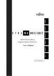
MOUNTING CHARGER
Step 1: Install two mounting bolts (M5 or gauge 10 having at least 8mm head)
onto the mounting surface that are 12.4 in. / 31.6cm apart as shown in Fig. A.
Step 2: Turn the lock mechanism to the unlocked position Fig.B.
Step 3A: Hook the charging unit onto the mounting surface by first sliding the
bottom slot over the bottom screw.
Step 3B: Align and fasten the top hole to the top screw.
*You may have to adjust the bolts for a tight and flush fit with the mounting surface.
Step 4: Lock the charging unit securely in place as shown in Fig. C.
To remove and insert battery pack, please see Page 20. Follow instructions to remove and insert
battery pack from Control Box.
M(E8&,_
M(E8&9_
M(E8&=_
258-&(>&Q&4287&CF
W>?*CP:A&!*%($(*>
21
'*CP:A&!*%($(*>
Alliance Service Manual
LEGACY ELECTRONICS
COMPONENTS
/F:#E:>CK&JD$$*>
9"$$:#K&(>A(C"$*#
9"$$:#K&`:%$&9D$$*>
=O"#E:#&!?DE
!:>A">$&!?DE
,C$D"$*#&!?DE
TROUBLE SHOOTING
The lights on the control box are not lit and I can’t charge?
• Make sure red re-set button is in up position
• Charger may be defective
• Batteries may be expired
The lights on the control box go to amber/red when I use the lift?
• The proper way to check battery levels is to not use the lift and depress the small blue
plus/minus button to the right of the window with the lights. As long as you have two or
more green lights you have a full charge.
CHECKING THE BATTERY
• Check batteries by pressing the Battery Testing Button (blue circle with a battery sign) on
the control box.
• Batteries are fully charged when all lights on the Battery Indicator are “ON”.
• Charge batteries when Indicator shown only one “GREEN” light.
• Do not use the lift when no “GREEN” light is shown. Charge the batteries immediately.
• Replace batteries when frequent charging is needed.
IMPORTANT NOTES ON CHARGING
• Push lift to charging location and charge the batteries with the charger provided.
Frequent plug/unplug of the hand control and motor into/from the control box may
damage the control box.
• Do not charge batteries over 12 hours.
<BCDEFC!8DGC!HDII!FJC!JKELBCE!HMDIE!NMBLODFOP
22
Alliance Service Manual
LEGACY ELECTRONICS
CHARGING THE BATTERY
•
•
•
•
•
•
•
Ensure the power is switched “ON” (the red “RESET” button should be up).
Insert charging plug into charging port on the control box.
Plug charger to power supply.
All lights of battery indicator should be “ON” while charging.
It takes approximately 2-3 hours to fully charge the batteries from one GREEN light.
It takes approximately 7-9 hours to fully charge the batteries from the RED light.
Do not charge battery for an extensive period of time. This will shorten the life of the
batteries.
• Do not let the batteries run down to the last RED light. This might shorten the life of the
batteries or damage the batteries.
• Unplug the charger first before using the lift.
WHAT THE COLOR LIGHTS MEAN
!"#!
!"#$%!
!"##$!
!"##$!
!"##$!
!
!"!
!"!
!"!
!"!
!"!
!"##$%&'()*+,!
!"!
!"!
!"!
!"#$!!!!!
56&5//
!"!
!""!
!""!
!""!
!""!
!""!
!""#$%&'()"!
!"#$%&'())&*(#+&,-.''*/01+'2!"#$%"#&'($!
!""!
!""!
!""!
!""!
!""!
!"#$!"%%&'(&)$*'$!"#$+*,,&+%(*,!
!
WARNING BUZZERS
The control box has a buzzer that provides you with information on the status
of the batteries and the lift. To stop the buzzer, push down the RESET button or
press the Battery Test button.
!"##$%&'()$! !"#!$%&!'"!
!"#$!
!!!""#$%$"&!
!"#$%&'(#))&$*&+'*,,&-*#)&./0!
!!!""#$%$"&!
!!!""#$%$"&!
!!!""#$%"&"'(%
!"#$%&'$(!)*&!
!!!"#$%&''()!
!"#$%&''()*!
!"#$%&'(#")*+,-./)012!
!"#$%&''()*!
!"#$%&'()*%+,-!
"#$%!&'(!)*++#$%!
!"#$%&'()$#"*!
!"#$!"%%&'(!
!"#$%&'()$#"*!
!"#$%&'(#()**+',,#$-#.*'$#*/0'$1#(*23,*%-4,*
!"#$%&"'%()*'+!
!
23
!"#$%&'(#))&$*&+'*,,&-*#)&./0!
!"#$%&'(#))&$*&+'*,,&!"#$%&'(!
!"#$%&"'(%))"*+",-!
!"#$$%$%&'(")'*'&+,(%&#(-(#)./0!
Alliance Service Manual
HYDRAULIC PUMP
COMPONENTS
0:?:"%:&9*?$
0-8-=1-!:58,
!DFI&c">A?:
0-8-=1-!Q65:
0:?:"%:&H>*J
TROUBLE SHOOTING
There is oil leaking from my pump?
• A slight amount of oil may be seen on the lifting shaft of the pump. This will not affect the
performance of the lift and may be wiped clean if desired.
• Fluid oil leaking from the bottom portion of the pump indicates a broken seal and the pump
should be replaced as soon as possible. Contact your dealer for assistance.
My pump will not lift the boom?
a& =O:CP&$*&F"P:&%D#:&$O:&OKA#"D?(C&IDFI&(%&(>%$"??:A&C*##:C$?K&N($O&$O:&#:A&P>*J&"$&$O:&
J*$$*F8&1)&"&IDFI&(%&(>%$"??:A&DI%(A:&A*N>&($&N(??&>*$&"??*N&">K&?()$(>E8
a& `D#>&$O:&#:A&#:?:"%:&P>*J&C*D>$:#&C?*CP&N(%:&)D??K&$*&$O:&*I:>&I*%($(*>8&!DFI&$O:&O">A?:&
B&$(F:%&">A&$O:>&#:U:#%:&$O:&#:A&P>*J&D>$(?&($&(%&)D??K&C?*%:A8&1>&F*%$&C"%:%&$O(%&N(??&)(@&
$O:&I#*J?:F&">A&$O:&IDFI&N(??&N*#P&"E"(>8&1)&($&%$(??&A*:%&>*$&N*#P&C*>$"C$&K*D#&A:"?:#&)*#&
"%%(%$">C:8
My pump goes up and then drops down slightly?
• Air may be trapped inside the pump. Use a Phillips screwdriver to open the release bolt on the
top side of the pump housing. Allow pump to lower all the way down. Tighten the release bolt
with the screwdriver and the pump should resume normal operation. If the pump continues to
malfunction it must be replaced and contact your dealer for assistance.
24
Alliance Service Manual
DIGITAL SCALE
COMPONENTS
R(E($"?&+C#::>
X))&9D$$*>
X>&Q&d:#*&9D$$*>
9"$$:#K&C*U:#
'98&Q&He&=*>U:#$:#&
9D$$*>
XI:#"$(*>&9D$$*>
BRACKET
"#:0Q
"#:0Q7
:0=2Q-,!/50
400,500,600Lb. Full Body
Electronic Lifts
6&
P/N 235.6&23526&23.-6&2355 6&
23546&235-6&235B6&2357
">A&23.5
:0=2Q-,!/50
P/N 23..6&23.L
TROUBLE SHOOTING
The display is faded?
• Check to make sure the 9v battery is connected properly.
• Check the battery level located at the bottom left corner of the display window.
When I turn on the scale it does not start at zero?
• Make sure there is no weight on the scale and press the “on/zero” button.
• There is also a “o” in the top left corner of the display window to indicate that the scale is set at
zero
The scale is giving me the wrong weight?
• Make sure to set the Lb/Kg button to the unit desired by just pressing the “Lb/Kg” button.
25
Alliance Service Manual
ACTUATORS
TROUBLE SHOOTING
The actuator stops and starts during lifting or lowering?
• Check battery levels and replace if needed
The actuator is stalled and a clicking sound is audible?
• Check to make sure actuator plug is firmly pushed into the control box
• Actuator may be broken or at end of life cycle
• PCB inside control box may be defective (call tech service)
The actuator will go up and or down but not both?
• Hand control may be defective
• Control box may be defective
The actuator makes a gridning noise when lifting a person but no noise when no load?
• Internal gear on actuator stripped and actuator needs repair or replacing
PENDANT
/
0;
X
M
/0
=
,T
f
=
e,
'/
!
TROUBLE SHOOTING
The lift does not go up or down?
• Make sure the pendent plug is securely attached to the control box.
• When using the Legacy pendant, there is a red light that comes on when buttons are pushed
to indicate that the pendant is getting power.
• The pendant has reach its life cycle and the pendant needs to be replaced
26
Alliance Service Manual
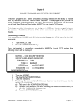
ADAPTOR
TESTING PROCEDURE
Step 1:
Plug the charger to the AC power supply
Step 2:
Set the digital voltmeter to DCV
Step 3:
Connect digital voltmeter red and black cables as in Figure 1
Step 4:
A reading at or above 26.7 volts indicates the charger is working properly
Step 5:
A reading under 26.7 volts means you need to replace the charger
Figure 1
27
Alliance Service Manual
MAINTENANCE AND INSPECTION
Stand Aid TRANSFER AID
The operator of the transfer aid shall inspect the Standing Transfer Aid before each use. Check all
bolts for tightness. Make sure the swivel seats can be easily turned and that all parts are in place.
Make sure that casters can be turned freely, and that caster brakes can be engaged. Make certain
all necessary items (i.e. slings, wheelchairs, etc.) are ready for use.
At least once a month, the transfer aid should be thoroughly inspected by a person qualified
to recognize any signs of wear and tear and looseness of bolts or parts. Replace any worn parts
immediately.
To lubricate, put a drop of oil on the following points when the Standing Transfer Aid is placed into
service and every month thereafter: Seat hinges and Caster Axles.
P/N 1914
P/N 1913
28
Alliance Service Manual
MAINTENANCE AND INSPECTION
STANDING TRANSFER AID TABLE
+CET
/+01,
0-2-+3-4
.56,789
X
X
-3-09!$!
.56,71
/0=.Check connections for improper connection,
looseness or wear.
Check the frame for bending and deflection.
X
:=1-!;!/55,!<-4=8
X
X
X
Check bolts and nuts for looseness.
Check casters and axle bolts for tightness.
Check rubber parts on the casters for deflection
X
X
Apply grease to caster ball bearings if needed.
X
Check welding joints for rust and crack.
28-=6+6>
,+&T//R/R
18+6>1!;!18+6>!7=04A=0X
X
Check sling for wear.
=O:CP&%?(>E&O"#AN"#:&:U:#K&$(F:&J:)*#:&D%:8
29
X
X
X
X
X
Alliance Service Manual
PARTS LIST AND COMPONENTS
Stand Aid STANDING TRANSFER AID
Parts List
1.
2.
3.
4.
5.
6.
7.
Cross Bar x 2
Right Side Arm
Left Side Arm
Side Support Arm x 2
Knee Pad Support Bar
Knee Pad x 2
Seat x 2
Tools & Fasteners
A1
A2
A3
A4
A5
A6
A7
T1
T2
8x
2x
4x
10x
10x
8x
2x
1x
1x
Carriage bolt
Hex bolt
Hex screw
Washer
Lock washer
Lock nut
Plastic cap
Wrench
Allen key
STA450-BASE
1913BASE
STA400-BASE
1914BASE
Factory assembled base with foot plate and castors.
30
Alliance Service Manual
MAINTENANCE AND INSPECTION
STANDING TRANSFER AID
PATIENT LIFT MAINTENANCE RECORD
LIFT MODEL:
SERIAL NUMBER:
DATE
SERVICE PERFORMED
PARTS APPLIED / REPLACED
31
MAINTENANCE PERFORMED BY
LIMITED PRODUCT WARRANTY. Subject to the terms below, DJO, LLC (“Company”) provides
the following limited product warranty relating to Chattanooga Alliance Patient Lifts (“Products”).
•
•
•
•
•
•
•
•
Lift frames and spreader bar: 3 years
Actuator: 2 years
Parts including casters, control box, PCB, pendant, charger: 2 years
Batteries: 1 year
Weigh Scale: 2 years
Stand Aid all components: 2 years
Hydraulic pumps: 1 year
Reusable slings: 6 months
The above warranty periods commence on the date of the original customer purchase of the Product
from Chattanooga or an authorized Chattanooga dealer. In the event of a defect in material or
workmanship, Company will repair or replace the defective component or the Product, at Company’s
option, without charge to customer, and Company shall be responsible for shipping expenses for
defective Products that are returned by the customer at Company’s request and for shipping expenses for
repaired or replaced Products that are shipped to the customer.
To make a warranty claim, Company’s Customer Care Department or Company’s authorized dealer
which sold the Product must be notified of the defect during the applicable warranty period above.
Products may not be returned by customer without a return authorization number. Products that are
returned for a warranty repair are typically repaired within 30 days from the date the Product is received
by Company, Company’s dealer or Company’s certified service center.
This warranty will be void if repairs or Product modifications are made by anyone other than Company,
Company’s dealer, or Company’s certified service center.
This warranty does not cover: (1) replacement parts or labor furnished by anyone other than Company,
Company’s dealer, or Company’s certified service center, (2) defects or damage caused by labor furnished
by anyone other than Company, Company’s dealer, or Company’s certified service center, or (3) any
malfunction or failure in a Product caused by abuse, accident or misuse, including but not limited to, the
failure to provide required maintenance or any use that is inconsistent with the Product User Manual.
Company is not responsible for injury, death or damage resulting from Product modifications or repairs
performed by service personnel which have not been authorized by Company. This warranty extends to
the original customer and is not transferable. This paragraph states the entire warranty relating to the
Product, and Company does not authorize any person or representative to modify this warranty.
COMPANY HEREBY DISCLAIMS ANY OTHER EXPRESS OR IMPLIED WARRANTIES NOT SET
FORTH IN THE FOREGOING LIMITED PRODUCT WARRANTY, INCLUDING, BUT NOT
LIMITED TO THE IMPLIED WARRANTIES OF MERCHANTABILITY OR FITNESS FOR A
PARTICULAR PURPOSE. COMPANY WILL NOT BE LIABLE FOR ANY INDIRECT, SPECIAL,
INCIDENTAL, OR CONSEQUENTIAL DAMAGES OR LOST PROFITS, CAUSED BY ANY
PRODUCT DEFECT WHETHER CLAIMS ARE BASED UPON TORT (INCLUDING NEGLIGENCE),
WARRANTY, CONTRACT OR OTHERWISE, EVEN IF COMPANY HAS BEEN ADVISED OF SUCH
POTENTIAL LOSS OR DAMAGE. TO THE EXTENT THE FOREGOING DISCLAIMERS ARE NOT
ALLOWED BY APPLICABLE LAW, ANY IMPLIED WARRANTIES WILL BE LIMITED TO THE
DURATION OF THE EXPRESS LIMITED WARRANTY PERIODS APPLICABLE TO THE PRODUCT
STATED ABOVE. SOME STATES DO NOT ALLOW LIMITATIONS ON HOW LONG AN IMPLIED
WARRANTY LASTS, OR THE EXCLUSION OR LIMITATION OF INCIDENTAL OR
CONSEQUENTIAL DAMAGES SO THE ABOVE LIMITATIONS MAY NOT APPLY TO CUSTOMER.
Alliance Service Manual
DJO, Inc.
1430 Decision Street
Vista, CA 92081 USA
T: 1-800-592-7329 USA
DJOGlobal.com
Alliance Service Manual
00-1342 Rev A 9/2013
© 2013 DJO, LLC. All rights reserved.
32