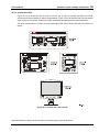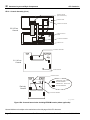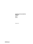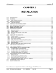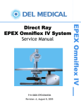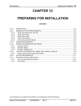
1
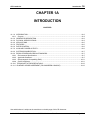
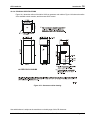
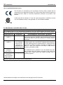
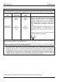
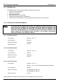
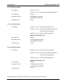
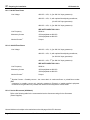
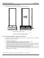
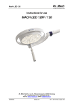
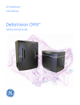
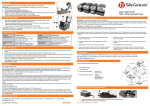
CPI Canada Inc
Pre-installation
1
CHAPTER 1
PRE-INSTALLATION
1.0
INTRODUCTION
1.1
Purpose
This manual applies to the Indico 100 family of generators and provides instructions for the installation
and maintenance of all models of that generator.
This Chapter contains the following sections.
SECTION
1A
1B
1C
1D
1E
TITLE
Introduction
Safety
Preparing for installation
Compatibility listing
Generator layout and Major Components
Use and disclosure is subject to the restrictions on the title page of this CPI document.
Indico 100 Series Service Manual
Ch # 740895-01
Rev. B
Page 1-1
1 Pre-installation
CPI Canada Inc
(This page intentionally left blank.)
Use and disclosure is subject to the restrictions on the title page of this CPI document.
Page 1-2
Rev. B
Indico 100 Series Service Manual
Ch # 740895-01
CPI Canada Inc.
Introduction
1A
CHAPTER 1A
INTRODUCTION
CONTENTS:
Section
Title
1A.1.0 INTRODUCTION ....................................................................................................................................1A-2
1A.1.1 Purpose...............................................................................................................................................1A-2
1A.2.0 GENERATOR DESCRIPTION ...............................................................................................................1A-2
1A.3.0 PHYSICAL SPECIFICATIONS...............................................................................................................1A-3
1A.4.0 APPLICATIONS......................................................................................................................................1A-5
1A.5.0 FEATURES.............................................................................................................................................1A-5
1A.6.0 ROTOR CONTROL ................................................................................................................................1A-6
1A.7.0 AUXILIARY POWER OUTPUTS ............................................................................................................1A-6
1A.8.0 SYSTEM DOCUMENTATION ................................................................................................................1A-7
1A.9.0 REGULATORIES AND DESIGN STANDARDS.....................................................................................1A-7
1A.9.1 Environmental Specifications..............................................................................................................1A-7
1A.9.2 Applicable Standards ..........................................................................................................................1A-7
1A.9.3 Electromagnetic Compatibility (EMC) ...............................................................................................1A-11
1A.9.4 RoHS Compliance ............................................................................................................................1A-11
1A.10.0 TECHNIQUE FACTORS DEFINITIONS .............................................................................................1A-12
1A.11.0 RUNTIME LICENSE AGREEMENT (TOUCHSCREEN CONSOLE)..................................................1A-12
Use and disclosure is subject to the restrictions on the title page of this CPI document.
Indico 100 Series Service Manual
Ch # 740904-00
Rev. Y
Page 1A-1
1A
Introduction
CPI Canada Inc.
1A.1.0 INTRODUCTION
1A.1.1 Purpose
This manual provides instructions for the installation and service of Indico 100 X-ray generators.
1A.2.0 GENERATOR DESCRIPTION
Depending on configuration and options, the generator provides the power and interfacing to operate X-ray
tubes, Buckys, Rad tables, GI (gastro-intestinal) tables, remote R&F tables, tomographic devices, and digital
imaging systems. The generator consists of power supply and control systems housed in the upper and
lower cabinets, a control console, and an optional remote fluoro control along with the necessary
interconnecting cable(s).
Major items provided are:
• X-ray generator housed in upper and lower cabinets.
• Control console.
• Optional remote fluoro control.
• Interconnecting cable(s).
• Operator's manual.
• Service and installation manual.
Use and disclosure is subject to the restrictions on the title page of this CPI document.
Page 1A-2
Rev. Y
Indico 100 Series Service Manual
Ch # 740904-00
CPI Canada Inc.
Introduction
1A
1A.3.0 PHYSICAL SPECIFICATIONS
Figure 1A-1 shows the outline of the Indico 100 X-ray generator main cabinet. Figure 1A-2 shows the outline
of the available control consoles, and the remote fluoro control.
Figure 1A-1: Generator outline drawing
Use and disclosure is subject to the restrictions on the title page of this CPI document.
Indico 100 Series Service Manual
Ch # 740904-00
Rev. Y
Page 1A-3
1A
Introduction
CPI Canada Inc.
1A.3.0 PHYSICAL SPECIFICATIONS (CONT)
Figure 1A-2 shows the outline of the Indico 100 control consoles, and the remote fluoro control.
Figure 1A-2: Console / remote fluoro control outline drawing
Use and disclosure is subject to the restrictions on the title page of this CPI document.
Page 1A-4
Rev. Y
Indico 100 Series Service Manual
Ch # 740904-00
CPI Canada Inc.
Introduction
1A
1A.4.0 APPLICATIONS
RAD SYSTEMS:
• Bucky table, tabletop and off-table radiography.
• Vertical bucky/cassette radiography.
• Conventional tomography.
R&F SYSTEMS:
• Fluoroscopic and spot film applications.
• Tomography with conventional and/or remote R&F tables.
• Optional digital compatible.
• Optional high-level fluoro for therapy simulators (Indico 100).
1A.5.0 FEATURES
•
•
•
•
•
•
•
•
•
•
•
•
•
•
•
•
•
High frequency generator.
One or two tube operation, Rad or Rad / Fluoro.
Single or dual filament supplies.
Low speed or dual speed X-ray tube stator supply.
Optimal matching of X-ray tubes by PROMs.
Repetitive self checks of generator functions, provides display of system faults and operating errors.
Optional AEC, up to four inputs.
Optional ABS with kV or kV/mA fluoro stabilizer.
Optional remote fluoro control box for tabletop use or SFD mounting.
Optional Dose-Area Product (DAP) display.
X-ray Tube protection. The generator allows setting the following limits:
a) Maximum mA, adjustable for each focal spot.
b) Maximum kV, adjustable for each X-ray tube.
c) Maximum kW, adjustable for each focal spot.
d) Maximum filament current limit, adjustable for large and small focal spots.
e) Anode heat warning and anode heat alarm levels.
Calibration features:
a) Microprocessor design allows all calibration and programming to be performed via the console.
b) mA calibration is automated.
Messages and diagnostic information: For users and service personnel, the generator console
displays various messages indicating status or equipment problems. The user is prompted in case of
errors.
Error log stores last 200 errors and associated generator settings.
Service and diagnostic information available via a laptop computer (optional).
KV range:
Radiography 40 to 150 kV.
Fluoroscopy 40 to 125 kV.
mA range:
Radiography 10 to 320 mA (30 kW), 10 to 400 mA (32 kW),
10 to 500 mA (40 kW), 10 to 630 mA (50 kW), 10 TO 800 mA (65 kW)
and 10 to 1000 mA (80 and 100 kW).
Fluoroscopy 0.5 to 10 mA, 0.5 to 20 mA with optional high-level fluoroscopy.
Normal and high-level pulsed fluoroscopy 5 to 80 mA.
Use and disclosure is subject to the restrictions on the title page of this CPI document.
Indico 100 Series Service Manual
Ch # 740904-00
Rev. Y
Page 1A-5
1A
Introduction
CPI Canada Inc.
1A.5.0 FEATURES (Cont)
•
•
mAs range:
Time range:
Tube dependent, max 1000 mAs.
Radiography 1.0 to 6300 ms.
Fluoroscopy 0 to 5 or 0 to 10 minutes.
Refer to the compatibility statement (end of section 1D) for compatibility and features of this specific
generator.
1A.6.0 ROTOR CONTROL
The generator will be equipped with a low speed starter, or optional dual speed starter.
DUAL SPEED STARTER
Number of tubes permissible:
Current monitoring
Dual speed starter output frequency
Braking
Rotor boost time
Duty cycle
LOW SPEED STARTER
Current monitoring
Duty cycle
Maximum of 32 tube types. Tube type is switch selectable
Both stator circuits
50 or 60 Hz (low speed)
150 or 180 Hz (high speed).
(Independent of line frequency)
Dynamic braking when in high speed rotation
Determined by tube selection plus incremental boost time
changes from 100 to 700 msec.
Not to exceed 2 high speed starts per minute.
Both stator circuits
Not to exceed 5 consecutive boosts, followed by a minimum 10
second wait period.
1A.7.0 AUXILIARY POWER OUTPUTS
The generator supplies the following power outputs for X-ray room equipment:
• 24 VDC, 4 Amp.
• 120 VAC, 2.5 Amp.
• 240 VAC, 1.5 Amp.
2.5 AMPS IS AVAILABLE AT 120 VAC OR 1.5 AMPS IS AVAILABLE AT 240 VAC, BUT BOTH ARE
NOT AVAILABLE SIMULTANEOUSLY.
The above voltage sources are not compatible with:
• Collimator lamps (24 VAC 150 watts). These lamps are not compatible with the 24 VDC supply.
• Fluorescent lamps. These have high starting currents and generate transients when the tube strikes.
• Some inductive loads may cause difficulties (some motors and solenoids).
Use and disclosure is subject to the restrictions on the title page of this CPI document.
Page 1A-6
Rev. Y
Indico 100 Series Service Manual
Ch # 740904-00
CPI Canada Inc.
Introduction
1A
1A.8.0 SYSTEM DOCUMENTATION
The Indico 100 series of X-ray generators includes the following documentation:
• Operator’s manual.
• Service and installation manual.
• Supplements and application notes as required.
1A.9.0 REGULATORIES AND DESIGN STANDARDS
1A.9.1 Environmental Specifications
OPERATING
Ambient temperature range
Relative humidity
Altitude
10 to 40 °C (50 to 104 °F).
20 to 80%, non-condensing.
-700 to 3000 meters (1100 to 700 hPa, 825 to 525 mm Hg).
TRANSPORT AND STORAGE
Ambient temperature range
-25 to 70 °C (-13 to 158 °F)..
Relative humidity
5 to 95%, non-condensing.
Atmospheric pressure range
-700 to 3000 meters (1100 to 700 hPa, 825 to 525 mm Hg).
•
•
•
Long-term storage over 40 °C will reduce the service life of electrolytic capacitors in
the generator.
The membrane control console is limited to a minimum temperature of -20°C, with a
maximum duration of 48 hours at that temperature. Transport and storage is limited to
a maximum duration of 120 hours between 50 and 70 °C, with an absolute humidity
not to exceed the humidity of 85% RH at 50 °C.
Touchscreen console temperatures below -20°C and above +50°C are limited to 10
days maximum duration, with a humidity not exceeding 50 % RH.
1A.9.2 Applicable Standards
A) SAFETY
The Indico 100 family of generators complies with the following regulatory requirements and design standards:
• FDA Center for Devices & Radiological Health (CDRH) - 21 CFR title 21 subchapter J (USA).
• Radiation Emitting Devices Act - C34 (Canada).
• Medical Device Regulations (Canada).
• EC Directive 93/42/EEC concerning Medical Devices (European Community).
• EN 60601-1/IEC 60601-1, EN 60601-2-7/IEC 60601-2-7, CSA 601.1, UL60601.1
-Type of protection against electric shock: Class I equipment.
-Degree of protection against electric shock: Not classified.
-Degree of protection against harmful ingress of water: Ordinary equipment.
-Mode of operation: Continuous operation with intermittent loading (standby - exposure).
-Equipment not suitable for use in presence of a flammable anesthetic mixture with air or with
oxygen or nitrous oxide.
• EN 60601-1-4/IEC 60601-1-4, EN ISO 14971.
NOTE: All referenced standards are considered to be at the latest adopted revision.
Use and disclosure is subject to the restrictions on the title page of this CPI document.
Indico 100 Series Service Manual
Ch # 740904-00
Rev. Y
Page 1A-7
1A
Introduction
CPI Canada Inc.
1A.9.2 Applicable Standards (con’t)
The CE Mark is a declaration by the manufacturer that the product complies with the
requirements of the applicable European Union (EU) medical device directive and that the
product has been subject to conformity assessment procedures as provided in that
directive.
A CSA mark with the indicators “C” and “US” means that product is certified for both the
U.S. and Canadian markets, to the applicable U.S. and Canadian standards.
B) EMC (EN 60601-1-2:2001/IEC 60601.1.2:2001)
Guidance and manufacturer’s declaration – electromagnetic emissions
The VZW2930 series of X-ray generators are intended for use in the electromagnetic environment specified
below. The customer or the user of the VZW2930 series should assure that it is used in such an environment.
Emissions test
Compliance
Electromagnetic environment - guidance
RF emissions
CISPR 11
Group 1
RF emissions
CISPR 11
Class A
(The VZW2930
series of X-ray
generators in
combination with
shielded location)
Not Applicable
The VZW2930 series of X-ray generators use RF energy only for
their internal functions. Therefore, the RF emissions are very low
and are not likely to cause any interference in nearby electronic
equipment.
The VZW2930 series of X-ray generators must be used only in a
shielded location with a minimum RF shielding effectiveness and,
for each cable that exits the shielded location, a minimum RF filter
attenuation of 40dB from 30 MHz to 230 MHz and 47dB from 230
MHz to 1 GHz. (The minimum at 30 MHz is 40dB and the
minimum at 230 MHz is 47dB).
Harmonic
The VZW2930 series is suitable for use in all establishments other
emissions
than domestic and those directly connected to the public lowIEC 61000-3-2
voltage power supply network that supplies buildings used for
Voltage
Not Applicable
domestic purposes.
fluctuations/
flicker emissions
IEC 61000-3-3
NOTE It is essential that the actual shielding effectiveness and filter attenuation of the shielded location be
verified to assure that they meet the minimum specifications.
Use and disclosure is subject to the restrictions on the title page of this CPI document.
Page 1A-8
Rev. Y
Indico 100 Series Service Manual
Ch # 740904-00
CPI Canada Inc.
Introduction
1A
Guidance and manufacturer’s declaration – electromagnetic immunity
The VZW2930 series of X-ray generators are intended for use in the electromagnetic environment specified
below. The customer or the user of the VZW2930 series should assure that it is used in such an environment.
Immunity
test
IEC 60601
test level
Compliance
level
Electromagnetic environment –
guidance
Electrostatic
discharge (ESD)
IEC 61000-4-2
Electrical fast
transient/burst
IEC 61000-4-4
± 6 kV contact
± 8 kV air
± 6 kV contact
± 8 kV air
Floors should be wood, concrete or ceramic tile.
If floors are covered with synthetic material, the
relative humidity should be at least 30%.
± 2 kV for power
supply lines
± 1 kV for
input/output lines
± 1 kV differential
mode
± 2 kV common
mode
< 5 % UT
(> 95 % dip in UT)
for 0.5 cycle
± 2 kV for power
supply lines
± 1 kV for
input/output lines
± 1 kV differential
mode
± 2 kV common
mode
< 5 % UT
(> 95 % dip in UT)
for 0.5 cycle
Mains power quality should be that of a typical
commercial or hospital environment.
40 % UT
(60 % dip in UT)
for 5 cycles
40 % UT
(60 % dip in UT)
for 5 cycles
70 % UT
(30 % dip in UT)
70 % UT
(30 % dip in UT)
< 5 % UT
(> 95 % dip in UT)
for 5 s
3 A/m
< 5 % UT
(> 95 % dip in UT)
for 5 s
3 A/m
Surge
IEC 61000-4-5
Voltage dips,
short interruption,
and voltage
variations on
power supply
input lines
IEC 61000-4-11
Mains power quality should be that of a typical
commercial or hospital environment.
Mains power quality should be that of a typical
commercial or hospital environment. If the user
of the VZW2930 series X-ray generator requires
continued operation during power mains
interruptions, it is recommended that the X-ray
generator be powered from an uninterruptible
power supply or battery.
Power frequency
Power frequency magnetic fields should be at
(50/60 Hz)
levels characteristic of a typical location in a
typical commercial or hospital environment
IEC 61000-4-8
NOTE: UT is the A.C. mains voltage prior to application of the test level.
Use and disclosure is subject to the restrictions on the title page of this CPI document.
Indico 100 Series Service Manual
Ch # 740904-00
Rev. Y
Page 1A-9
1A
Introduction
CPI Canada Inc.
Guidance and manufacturer’s declaration – electromagnetic immunity
The VZW2930 series of X-ray generators are intended for use in the electromagnetic environment specified
below. The customer or the user of the VZW2930 series should assure that it is used in such an environment.
Immunity
test
IEC 60601
test level
Compliance
level
Electromagnetic environment - guidance
Conducted RF
IEC 61000-4-6
3 Vrms
150 kHz to
80MHz
3 Vrms
150 kHz to
80MHz
Radiated RF
IEC 61000-4-3
3 V/m
80MHz to 2.5
GHz
3 V/m
80MHz to 2.5
GHz
The VZW2930 series of X-ray generators must be
used only in a shielded location with a minimum RF
shielding effectiveness and, for each cable that
enters the shielded location, a minimum RF filter
attenuation of 40dB from 30 MHz to 230 MHz and
47dB from 230 MHz to 1 GHz. (The minimum at 30
MHz is 40dB and the minimum at 230 MHz is
47dB.)
Field strengths outside the shielded location from
fixed RF transmitters, as determined by an
electromagnetic site survey, should be less than 3
V/m.a
Interference may occur in the vicinity of equipment
marked with the following symbol:
NOTE 1 These guidelines may not apply all situations. Electromagnetic propagation is affected by absorption
and reflection from structures, objects and people.
NOTE 2 It is essential that the actual shielding effectiveness and filter attenuation of the shielded location be
verified to assure that they meet the minimum specification.
a
Field strengths from fixed transmitters, such as base stations for radio (cellular/cordless) telephones and
land mobile radios, amateur radio, AM and FM radio broadcast and TV broadcast cannot be predicted
theoretically with accuracy. To assess the electromagnetic environment due to fixed RF transmitters, an
electromagnetic site survey should be considered. If the measured field strength in the location in which the
VZW2930 series of X-ray generators is used exceeds the applicable RF compliance level above, the X-ray
generator should be observed to verify normal operation. If abnormal performance is observed, additional
measures may be necessary, such as re-orienting or relocating the X-ray generator.
Use and disclosure is subject to the restrictions on the title page of this CPI document.
Page 1A-10
Rev. Y
Indico 100 Series Service Manual
Ch # 740904-00
CPI Canada Inc.
Introduction
1A
1A.9.3 Electromagnetic Compatibility (EMC)
In accordance with the intended use, this X-ray generator complies with the European Council Directive
concerning Medical Devices. The CE marking affixed to this product signifies this. One of the harmonized
standards of this Directive defines the permitted levels of electromagnetic emission from this equipment
and its required immunity from the electromagnetic emissions of other devices.
It is not possible, however, to exclude with absolute certainty the possibility that other high frequency
electronic equipment, which is fully compliant to the EMC regulations, will not adversely affect the
operation of this generator. If the other equipment has a comparatively high level of transmission power
and is in close proximity to the generator, these EMC concerns (the risk of interference) may be more
pronounced. It is therefore recommended that the operation of equipment of this type such as mobile
telephones, cordless microphones and other similar mobile radio equipment be restricted from the vicinity
of this X-ray generator.
1A.9.4 RoHS Compliance
Indico 100
产品中有毒有害物质或元素的名称及含量
Table of hazardous substances’ name and concentration.
有毒有害物质或元素
部件名称
Hazardous substances’ name
Component Name
铅
汞
镉
六价铬
多溴联苯
(Pb)
(Hg)
(Cd)
(Cr(VI))
(PBB)
多溴二苯醚
(PBDE)
Generator
X
O
O
X
O
O
Console
X
O
O
X
O
O
O: 表示该有毒有害物质在该部件所有均质材料中的含量均在SJ/T11363-2006 标准规定的限量要求以下
X: 表示该有毒有害物质至少在该部件的某一均质材料中的含量超出SJ/T11363-2006 标准规定的限量要求
• 此表所列数据为发布时所能获得的最佳信息
• 由于缺少经济上或技术上合理可行的替代物质或方案,此医疗设备运用以上一些有毒有害物质来实
现设备的预期临床功能,或给人员或环境提供更好的保护效果。
O: Indicates that this toxic or hazardous substance contained in all of the homogeneous materials for
this part is below the limit requirement in SJ/T11363-2006.
X: Indicates that this toxic or hazardous substance contained in at least one of the homogeneous
materials used for this part is above the limit requirement in SJ/T11363-2006.
• Data listed in the table represents best information available at the time of publication
• Applications of hazardous substances in this medical device are required to achieve its intended
clinical uses, and/or to provide better protection to human beings and/or to environment, due to
lack of reasonably (economically or technically) available substitutes.
Use and disclosure is subject to the restrictions on the title page of this CPI document.
Indico 100 Series Service Manual
Ch # 740904-00
Rev. Y
Page 1A-11
1A
Introduction
CPI Canada Inc.
1A.10.0 TECHNIQUE FACTORS DEFINITIONS
•
•
KV:
TIME:
•
•
mA:
mAs
KV peak after any initial kV overshoot.
Time in milliseconds, (ms) that the high voltage (anode to cathode) is greater than or
equal to 75% of the desired kV.
Average tube current (in mA) during the exposure time.
milliampere-seconds (mA x TIME).
1A.11.0 RUNTIME LICENSE AGREEMENT (TOUCHSCREEN CONSOLE)
User / End User License Agreement
You should carefully read the following terms and conditions before using this product. It contains
software (“Software”), the use of which is licensed by Communications & Power Industries Canada Inc.
(“CPI”) to you, the original end user, for your use only as set forth below. If you do not agree to the terms
and conditions of the agreement, do not use the software. If you use any part of the software, such use
shall indicate that you accept these terms.
1. The Software embedded in this Product is protected by international intellectual property rights and
treaties. You may use the software in object code form only and are prohibited from distributing the
software as such. There is no grant of any of the Software’s proprietary source code. This license
does not grant you any rights to patents, copyright, trade secrets, trademarks, or any other rights with
respect to the Software. You are not authorized to modify or to create derivative works based on this
software. You are not authorized to decompile, disassemble or otherwise reverse engineer the
embedded Software. CPI reserves all rights not expressly granted herein.
2. You are authorized to copy the Software only for the following purposes.
a. If such copying is an essential step in the use of the Software and in accordance with this
agreement; or
b. To make an archival copy for back up purposes.
3. If making a copy pursuant to Section 2 above, you must ensure that all trademark, copyright and
intellectual property notices are reproduced and included on any copies that are made.
4. The Software embedded in this Product is provided to you within the same warranty terms, as those
offered for the Products, except for any third party software, which is offered “as is” and without
warranties of any kind including, but not limited to: warranties of merchantability, fitness for a
particular purpose, title and non-infringement.
5. The Software embedded in this Product is not intended for use in or with systems, devices, or
products intended to support of sustain life or for any aviation or nuclear reactor application in which
the software or its failure, malfunction, or inadequacy could directly or indirectly cause or contribute to
personal injury or death or significant property damage. It is your responsibility, as the User or End
User, to ascertain the suitability of the Software for your particular situation and / or application.
6. This agreement is effective until terminated. The agreement shall terminate immediately if you fail to
adhere to the terms and conditions set forth herein. Upon termination, you must immediately cease
all use of the Software and destroy any and all copies of the embedded Software in your possession.
7. This agreement represents the entire agreement between you and CPI with respect to the Software,
and supersedes all other agreements or representations, whether written or oral. The terms of this
agreement can only be modified by the express written consent ob both parties. If any part of this
agreement is held to be unenforceable as written, it will be enforced to the maximum extent allowed
by applicable law, and without effect to the enforceability of any other part.
8. Should you have questions regarding the use of the Software, please contact [email protected].
Use and disclosure is subject to the restrictions on the title page of this CPI document.
Page 1A-12
Rev. Y
Indico 100 Series Service Manual
Ch # 740904-00
CPI Canada Inc.
Introduction
1A
Address any questions regarding X-ray generator operation to:
Mail:
Customer Support Department
Communications and Power Industries Canada Inc.
45 River Drive
Georgetown, Ontario, Canada L7G 2J4
Telephone:
(905) 877-0161
Fax:
(905) 877-8320
Attention: Customer Support Department
E-mail:
[email protected]
Attention: Customer Support Department
Use and disclosure is subject to the restrictions on the title page of this CPI document.
Indico 100 Series Service Manual
Ch # 740904-00
Rev. Y
Page 1A-13
1A
Introduction
CPI Canada Inc.
(This page intentionally left blank)
Use and disclosure is subject to the restrictions on the title page of this CPI document.
Page 1A-14
Rev. Y
Indico 100 Series Service Manual
Ch # 740904-00
CPI Canada Inc.
Safety
1B
CHAPTER 1B
SAFETY
CONTENTS:
Section
Title
1B.1.0 INTRODUCTION........................................................................................................................................... 2
1B.2.0 SAFETY AND WARNING SYMBOLS........................................................................................................... 2
1B.3.0 SAFETY NOTICES AND WARNINGS.......................................................................................................... 2
1B.4.0 SAFETY WARNINGS LABELS..................................................................................................................... 5
1B.4.2 Caution High Voltage Exposed Label ....................................................................................................... 6
1B.4.3 Weight Label.............................................................................................................................................. 6
1B.4.4 Caution High Voltage Behind Cover ......................................................................................................... 7
1B.4.5 Caution High Voltage ................................................................................................................................ 7
1B.4.6 Danger High Voltage Exposed .................................................................................................................. 8
1B.4.7 Console CPU Board / Console Board ....................................................................................................... 8
1B.4.8 Generator Interface Board......................................................................................................................... 8
1B.4.9 Room Interface Board ............................................................................................................................... 9
1B.4.10 AEC Board................................................................................................................................................. 9
1B.4.11 Power Input Board..................................................................................................................................... 9
1B.4.12 Low Speed Starter Board .......................................................................................................................... 9
1B.4.13 Dual Speed Starter Board ......................................................................................................................... 9
1B.4.14 Inverter Board............................................................................................................................................ 9
1B.4.15 HT Tank................................................................................................................................................... 10
1B.4.16 F1 - Primary of Power Supply Auxiliary Transformer.............................................................................. 10
1B.4.17 F4 - Primary of Room Interface Transformer .......................................................................................... 10
Use and disclosure is subject to the restrictions on the title page of this CPI document.
Indico 100 Series Service Manual
Ch # 740904-01
Rev. V
Page 1B-1
1B
Safety
CPI Canada Inc.
1B.1.0 INTRODUCTION
This section contains important safety warnings and safety information required for installing and
servicing the generator.
1B.2.0 SAFETY AND WARNING SYMBOLS
The following advisory symbols are used on the safety warning labels, and/or on circuit boards, and/or on
the operator console and the optional remote fluoro control.
High voltage symbol used to indicate the presence
of high voltage.
WARNING
THIS X-RAY UNIT MAY BE
DANGEROUS TO PATIENT AND
OPERATOR UNLESS SAFE
EXPOSURE FACTORS,
OPERATING INSTRUCTIONS
AND MAINTENANCE
SCHEDULES ARE OBSERVED.
Warning symbol used to indicate a potential hazard
to operators, to service personnel, or to the
equipment. It indicates a requirement to refer to the
accompanying documentation for details.
Radiation exposure symbol used on operator
console. Lights to indicate that an exposure is in
progress. This is accompanied by an audible tone
from the console.
Fluoro radiation exposure symbol used on operator
console and on optional remote fluoro control unit.
Lights to indicate that a fluoro exposure is in
progress. This is accompanied by an audible tone
from the console.
Radiation warning label on console, used in certain
jurisdictions.
Never allow unqualified personnel to operate the Xray generator.
1B.3.0 SAFETY NOTICES AND WARNINGS
WARNING:
PROPER USE AND SAFE OPERATING PRACTICES WITH RESPECT TO X-RAY
GENERATORS ARE THE RESPONSIBILITY OF USERS OF SUCH GENERATORS. CPI
CANADA INC. PROVIDES INFORMATION ON ITS PRODUCTS AND ASSOCIATED
HAZARDS, BUT ASSUMES NO RESPONSIBILITY FOR AFTER-SALE OPERATING AND
SAFETY PRACTICES.
THE MANUFACTURER ACCEPTS NO RESPONSIBILITY FOR ANY GENERATOR NOT
MAINTAINED OR SERVICED ACCORDING TO THIS SERVICE AND INSTALLATION
MANUAL, OR FOR ANY GENERATOR THAT HAS BEEN MODIFIED IN ANY WAY.
THE MANUFACTURER ALSO ASSUMES NO RESPONSIBILITY FOR X-RAY RADIATION
OVEREXPOSURE OF PATIENTS OR PERSONNEL RESULTING FROM POOR OPERATING
TECHNIQUES OR PROCEDURES.
Use and disclosure is subject to the restrictions on the title page of this CPI document.
Page 1B-2
Rev. V
Indico 100 Series Service Manual
Ch # 740904-01
CPI Canada Inc.
Safety
1B
1B.3.0 SAFETY NOTICES AND WARNINGS (Cont)
WARNING:
THIS X-RAY UNIT MAY BE DANGEROUS TO PATIENT AND OPERATOR UNLESS SAFE
EXPOSURE FACTORS, OPERATING INSTRUCTIONS AND MAINTENANCE SCHEDULES
ARE OBSERVED.
X-ray radiation exposure may be damaging to health, with some effects being cumulative and extending
over periods of many months or even years. Operators and service personnel should avoid any
exposure to the primary beam and take protective measures to safeguard against scatter radiation.
Scatter radiation is caused by any object in the path of the primary beam and may be of equal or less
intensity than the primary beam that exposes the film.
No practical design can incorporate complete protection for operators or service personnel who do not
take adequate safety precautions. Only authorized and properly trained service and operating
personnel should be allowed to work with this X-ray generator equipment. The appropriate
personnel must be made aware of the inherent dangers associated with the servicing of high voltage
equipment and the danger of excessive exposure to X-ray radiation during system operation.
DO NOT CONNECT UNAPPROVED EQUIPMENT TO THE REAR OF THE CONSOLE.
For the 23 X 56 (cm) console, J5 is used for the interconnect cable to the generator main
cabinet, J4 is not used, J2 is a serial port for use by an external computer, and J1 is for
connection of an optional printer.
For the 31 X 42 (cm) console, J5 is used for the interconnect cable to the generator main
cabinet, J2 is a serial port for use by an external computer, and J13 is for connection of an
external hand switch and / or foot switch.
For the Rad-only console, J3 is for connection of an external hand switch, J4 is a serial port for
use by an external computer, and J8 is for the interconnect cable to the main cabinet.
For the touchscreen console, GEN on the rear of the touchscreen is for the interconnect cable
to the generator main cabinet, HS is for connection of an external hand switch, COM 1 & COM
2 are serial ports for use by external devices, LO (3.5 mm stereo jack) is for customer supplied
speakers (minimum 8 ohms, do not use externally amplified speakers), ETH is a standard
10/100 ethernet connection, USBA and USBB are USB ports for connection of external
devices, CF is for the compact flash memory card which holds the touchscreen software and
SW1 is the console upgrade button.
INCORRECT CONNECTIONS OR USE OF UNAPPROVED EQUIPMENT MAY RESULT IN
INJURY OR EQUIPMENT DAMAGE.
CAUTION:
DO NOT EXCEED THE TUBE MAXIMUM OPERATING LIMITS. INTENDED LIFE AND
RELIABILITY WILL NOT BE OBTAINED UNLESS GENERATORS ARE OPERATED WITHIN
PUBLISHED SPECIFICATIONS.
WARNING:
HAZARDOUS VOLTAGES EXIST INSIDE THE GENERATOR WHENEVER THE MAINS
POWER IS SWITCHED ON. THESE AREAS INCLUDE THE MAIN FUSE HOLDER AND
PORTIONS OF THE POWER INPUT BOARD, PARTS OF THE GENERATOR INTERFACE
BOARD AND ROOM INTERFACE BOARD, THE PRIMARY OF THE ROOM INTERFACE
TRANSFORMER, AND THE TERMINALS ON THE LINE ADJUSTING TRANSFORMER, IF
FITTED.
THE CONSOLE ON/OFF SWITCH DOES NOT DISCONNECT THE MAINS POWER FROM
THE ABOVE AREAS INSIDE THE GENERATOR.
Use and disclosure is subject to the restrictions on the title page of this CPI document.
Indico 100 Series Service Manual
Ch # 740904-01
Rev. V
Page 1B-3
1B
Safety
CPI Canada Inc.
1B.3.0 SAFETY NOTICES AND WARNINGS (Cont)
NOTE:
THE DC BUS CAPACITORS MAY PRESENT A SAFETY HAZARD FOR AT LEAST 5
MINUTES AFTER THE POWER HAS BEEN REMOVED FROM THE UNIT. CHECK THAT
THESE CAPACITORS ARE FULLY DISCHARGED BEFORE SERVICING THE GENERATOR.
NOTE:
WHEN CONNECTING ADDITIONAL EQUIPMENT TO THE GENERATOR, IT IS THE
RESPONSIBILITY OF THE INSTALLER TO VERIFY COMPLIANCE TO ALL REGULATORY
STANDARDS FOR SAFETY, EMC, AND HAZARD ANALYSIS / RISK ASSESSMENT OF THE
FINAL SYSTEM CONFIGURATION.
The following notes apply to the touchscreen console only.
WARNING:
THE TOUCHSCREEN CONSOLE HAS NO USER SERVICEABLE PARTS.
ATTEMPT TO OPEN THE TOUCHSCREEN CONSOLE.
NOTE:
WHEN ATTACHING THE BASE TO THE TOUCHSCREEN CONSOLE ENSURE THE
TOUCHSCREEN IS RESTING ON A FLAT, CLEAN SURFACE WITH A PIECE OF NONABRASIVE MATERIAL BETWEEN THE TOUCHSCREEN AND THE SURFACE.
NOTE:
TO AVOID ACCIDENTAL CONTACT WITH ENERGIZED CIRCUITRY INSIDE THE
TOUCHSCREEN CONSOLE, THE MAXIMUM BACK PLATE SCREW LENGTH MUST BE
LIMITED TO 25 mm (1 inch).
NOTE:
FOR WALL MOUNTED TOUCHSCREEN CONSOLES ENSURE THE BASE IS SECURED
PROPERLY TO A WALL STUD.
WARNING:
PLEASE ENSURE THERE IS SUFFICIENT AREA AROUND THE VENTING SLOTS OF THE
TOUCHSCREEN CONSOLE TO ALLOW PROPER COOLING OF THE INTERNAL
COMPONENTS.
NOTE:
THE SET SCREW COLLAR MUST BE POSITIONED ON THE UPPER HALF OF THE TILT
ARM TO PREVENT PERSONAL INJURY SHOULD THE TOUCHSCREEN SLIP WHILE
ADJUSTING THE VIEWING HEIGHT.
DO NOT
USE THE PROVIDED ALLEN KEY TO ENSURE THE SET SCREW COLLAR IS LOCKED
INTO POSITION SUCH THAT THERE IS NO LESS THAN 25 mm (1 INCH) OF CLEARANCE
BETWEEN BOTTOM EDGE OF THE TOUCHSCREEN CONSOLE AND THE TOUCHSCREEN
BASE PLATE WHEN THE TOUCHSCREEN IS ADJUSTED TO ITS MINIMUM HEIGHT.
PLEASE BE SURE TO SUPPORT THE TOUCHSCREEN CONSOLE WHEN ADJUSTING ITS
VIEWING POSITION.
Use and disclosure is subject to the restrictions on the title page of this CPI document.
Page 1B-4
Rev. V
Indico 100 Series Service Manual
Ch # 740904-01
CPI Canada Inc.
Safety
1B
1B.4.0 SAFETY WARNINGS LABELS
This section describes the safety labels used inside and outside the generator cabinet. Depending on
configuration, your X-ray generator may contain some or all of the labels shown.
NOTE:
THESE LABELS AND WARNINGS ARE INTENDED TO ALERT SERVICE PERSONNEL THAT
SERIOUS INJURY WILL RESULT IF THE HAZARD IDENTIFIED IS IGNORED.
NOTE:
DUE TO THE DIVERSITY OF GENERATOR MODELS, THE EQUIPMENT MAY NOT BE
EXACTLY AS SHOWN.
WARNING:
SWITCH OFF THE MAIN POWER DISCONNECT AND ALLOW SUFFICIENT TIME FOR ALL
CAPACITORS TO DISCHARGE BEFORE REMOVING ANY COVERS OR PANELS.
WARNING:
IF ANY BARRIERS OR COVERS MUST BE REMOVED FOR SERVICE, TAKE ALL
REQUIRED PRECAUTIONS WITH RESPECT TO THE HAZARD(S) AND IMMEDIATELY
REPLACE THE BARRIERS / COVERS WHEN THE NEED FOR REMOVAL IS COMPLETED.
REPLACE ALL FUSES IN THIS GENERATOR WITH THE SAME TYPE AND
RATING.
This information is provided to help you establish safe operating conditions for both you and your 100 kHz series
X-ray generator. Do not operate this X-ray generator except in accordance with these precautions, and any
additional information provided by the X-ray generator manufacturer and/or competent safety authorities.
1B.4.1 High Voltage / High Energy DC Bus
This label is attached to the main access panel on the generator cabinet. The internal capacitors may
hold a lethal charge for up to 5 minutes after the console or the main power disconnect is switched off. Do
not remove the cover for a minimum of 5 minutes after the power has been switched off.
Use and disclosure is subject to the restrictions on the title page of this CPI document.
Indico 100 Series Service Manual
Ch # 740904-01
Rev. V
Page 1B-5
1B
Safety
CPI Canada Inc.
1B.4.0 SAFETY WARNINGS LABELS (Cont)
WARNING:
WAIT A MINIMUM OF 5 MINUTES AFTER THE INPUT MAINS POWER HAS BEEN REMOVED
BEFORE REMOVING ANY COVERS OR ACCESS PANELS. ONCE THE COVER(S) /
PANEL(S) ARE REMOVED CHECK THAT THE VOLTAGE ACROSS THE DC BUS
CAPACITORS IS LESS THAN 48 VDC BEFORE SERVICING. IF THIS VOLTAGE EXCEEDS
48 VDC, THE CAPACITORS MUST BE MANUALLY DISCHARGED BY QUALIFIED SERVICE
PERSONNEL.
1B.4.2 Caution High Voltage Exposed Label
This label is attached to the main access panel on the generator cabinet. High voltage will be exposed if
the subject panel is removed and the generator is connected to live AC mains, or if high voltage
capacitors are still charged.
1B.4.3 Weight Label
This label is attached to the main access panel on the generator cabinet, and to the HT oil tank. This
states the approximate weight of the generator and the HT oil tank, and cautions against attempting to lift
those assemblies without proper assistance.
Use and disclosure is subject to the restrictions on the title page of this CPI document.
Page 1B-6
Rev. V
Indico 100 Series Service Manual
Ch # 740904-01
CPI Canada Inc.
Safety
1B
1B.4.4 Caution High Voltage Behind Cover
This label is attached to a cover over the inverter board(s). The inverter assembly is connected to the
main DC bus and will have high voltage applied at all times that the generator is switched on. This
assembly will remain energized for up to 5 minutes after the generator is switched off or the main
disconnect is switched off.
This label is also attached to a cover over the main input fuses on the power input board. This area will
have mains voltage applied as long as the main disconnect is switched on.
1B.4.5 Caution High Voltage
This label is attached to the room interface transformer. This transformer has mains voltage on the
primary terminals at all times that the generator is connected to live AC mains.
This label is attached to the resonant assembly. The resonant board will have exposed high voltage at all
times that the DC bus is charged.
On Indico 100 SP generators, this label is also attached to the power leads for the cooling fan near the
power input board. This fan operates from 120 VAC (as do all cooling fans in the generator).
Use and disclosure is subject to the restrictions on the title page of this CPI document.
Indico 100 Series Service Manual
Ch # 740904-01
Rev. V
Page 1B-7
1B
Safety
CPI Canada Inc.
1B.4.6 Danger High Voltage Exposed
This label is attached to the primary terminals on the HT oil tank. These terminals may be energized at all
times that the generator is switched on, and for 5 minutes after the console or the main disconnect is
switched off.
1B.4.7 Console CPU Board / Console Board
For 23 X 56 (cm) consoles:
HIGH VOLTAGE HAZARD: Approximately 400 VAC is present on this board in the area of
U32 and J10. This voltage is used to light the backlight for the LCD display assembly in the
console.
For 31 X 42 (cm) Indico 100 R&F consoles:
HIGH VOLTAGE HAZARD: Approximately 400 VAC is present on this board in the area of T1,
C61, and J10. This is a high voltage source for the fluorescent backlight on the LCD display.
For Indico 100 Rad-only consoles:
HIGH VOLTAGE HAZARD: Approximately 400 VAC is present on this board in the area of T1,
C36, and J5. This is a high voltage source for the fluorescent backlight on the LCD display.
Fuse rating (Indico 100 Rad-only console)
F1:
GDC-1 (1A 250V slow blow).
For CPI Touchscreen consoles:
HIGH VOLTAGE HAZARD: Approximately 700 VAC is present on the touchscreen board in
the areas of T1, C7, C12, J1, J5 and T2, C106, C94, J26, J19. This is a high voltage source
for the fluorescent backlight on the LCD display.
1B.4.8 Generator Interface Board
HIGH VOLTAGE HAZARD: Components within the dashed line on the board have high
voltage applied at all times that the main disconnect is switched ON. These components are
live EVEN WITH THE CONSOLE SWITCHED OFF.
FUSE RATINGS:
F1
GDC-1.6 (1.6A 250V slow blow).
F2
GDC-2.5 (2.5A 250V slow blow).
F3, F4, F5 GDC-5 (5A 250V slow blow).
F6
GDC-2(2A 250V slow blow).
Use and disclosure is subject to the restrictions on the title page of this CPI document.
Page 1B-8
Rev. V
Indico 100 Series Service Manual
Ch # 740904-01
CPI Canada Inc.
Safety
1B
1B.4.9 Room Interface Board
HIGH VOLTAGE HAZARD: 110 / 220 VAC may be present on this board at all times that the
AC mains for the generator is switched on.
1B.4.10 AEC Board
HIGH VOLTAGE HAZARD: AEC board assemblies with an integral high voltage supply for
ion chambers or for a PMT may have high voltage present, up to approximately 1000 VDC, at
all times that the generator is switched on.
1B.4.11 Power Input Board
HIGH VOLTAGE HAZARD: High voltage is present on this board whenever the generator is
connected to live AC mains.
The DC bus capacitors will remain charged for up to 5 minutes after the generator has been
switched off.
BURN HAZARD: Power input boards for single phase generators are fitted with several high
power resistors that operate at temperatures sufficient to cause skin burn. Ensure that these
resistors have cooled sufficiently after the power has been switched off before servicing.
1B.4.12 Low Speed Starter Board
HIGH VOLTAGE HAZARD: High voltage is present on this board whenever the generator is
switched on.
BURN HAZARD: This board is fitted with high power resistors that operate at temperatures
sufficient to cause skin burn. Ensure that these resistors have cooled sufficiently after the
power has been switched off before servicing.
1B.4.13 Dual Speed Starter Board
HIGH VOLTAGE HAZARD: Approximately 600 VDC is present on this board whenever the
generator is switched on. This voltage is sourced from the DC bus capacitors in the generator,
and therefore the high voltage hazard will remain for up to 5 minutes after the generator has
been switched off.
1B.4.14 Inverter Board
HIGH VOLTAGE HAZARD: The inverter boards are connected to the main DC bus and will
have high voltage applied at all times that the generator is switched on. This assembly will
remain energized for up to 5 minutes after the generator is switched off, or the main
disconnect is switched off.
Use and disclosure is subject to the restrictions on the title page of this CPI document.
Indico 100 Series Service Manual
Ch # 740904-01
Rev. V
Page 1B-9
1B
Safety
CPI Canada Inc.
1B.4.15 HT Tank
HIGH VOLTAGE HAZARD: High voltage may be present at the primary terminals on the tank
lid board, at the output high voltage connectors, and at the mA/mAs measuring jacks if the
shorting link is opened for mA/mAs measurements.
The generator must not be energized if the leads that attach to the primary of the high voltage
transformer are disconnected.
TORQUE NOTICE: Do not over-tighten the nuts on the feed through terminals for the primary
of the HT transformers. Over tightening may damage the HT tank.
1B.4.16 F1 - Primary of Power Supply Auxiliary Transformer
FUSE RATING: Fuse F1 is located on the generator chassis, to the left of the main input
fuses on the power input board.
Single phase generators: FNM-3 (3A 250V).
Three phase generators: FNQ-2 (2A 500V).
1B.4.17 F4 - Primary of Room Interface Transformer
FUSE RATING: Fuse F4 is located on the generator chassis, to the left of the main input
fuses on the power input board.
Single phase generators: FNM-3 (3A 250V).
Three phase generators: FNQ-2 (2A 500V).
Use and disclosure is subject to the restrictions on the title page of this CPI document.
Page 1B-10
Rev. V
Indico 100 Series Service Manual
Ch # 740904-01
CPI Canada Inc.
Preparing for Installation
1C
CHAPTER 1C
PREPARING FOR INSTALLATION
CONTENTS:
1C.1.0 INTRODUCTION ................................................................................................................................... 1C-2
1C.2.0 GENERATOR POWER REQUIREMENTS ........................................................................................... 1C-2
1C.2.1 32 kW Single Phase........................................................................................................................... 1C-2
1C.2.2 40 kW Single Phase........................................................................................................................... 1C-2
1C.2.3 32 kW Three Phase ........................................................................................................................... 1C-2
1C.2.4 40 kW Three Phase ........................................................................................................................... 1C-3
1C.2.5 50 kW Three Phase ........................................................................................................................... 1C-3
1C.2.6 65 kW Three Phase ........................................................................................................................... 1C-3
1C.2.7 80 kW Three Phase ........................................................................................................................... 1C-4
1C.2.8 100 kW Three Phase ......................................................................................................................... 1C-4
1C.2.9 Service Disconnect (All Models) ........................................................................................................ 1C-4
1C.3.0 POWER LINE REQUIREMENTS .......................................................................................................... 1C-5
1C.4.0 GROUND REQUIREMENTS................................................................................................................. 1C-7
1C.5.0 OUTLINE DRAWINGS .......................................................................................................................... 1C-7
1C.5.1 Generator Outline ................................................................................................................................. 1C-7
1C.5.2 Generator Weight ................................................................................................................................. 1C-7
1C.5.3 Generator Shipping Containers: Dimensions ....................................................................................... 1C-8
1C.6.0 LOCATING THE GENERATOR CABINET AND CONTROLLER......................................................... 1C-8
1C.6.1 Locating The Equipment In The X-Ray Room ................................................................................... 1C-9
1C.6.2 Seismic Centers and mounting hole locations................................................................................. 1C-10
1C.7.0 ENVIRONMENTAL REQUIREMENTS ............................................................................................... 1C-12
1C.8.0 CABLES SUPPLIED WITH THE INDICO 100 GENERATOR ............................................................ 1C-12
1C.9.0 PRE-INSTALLATION CHECK LISTS.................................................................................................. 1C-13
1C.9.1 Site Logistics .................................................................................................................................... 1C-13
1C.9.2 Installation Equipment...................................................................................................................... 1C-13
Use and disclosure is subject to the restrictions on the title page of this CPI document.
Indico 100 Series Service Manual
Ch # 740895-02
Rev. Y
Page 1C-1
1C
Preparing for Installation
CPI Canada Inc.
1C.1.0 INTRODUCTION
The following items must be considered before installing your generator:
• Power level of your generator.
• Power line requirements.
• Ground requirements.
• Physical placement of the generator.
• Environmental requirements for the generator.
• Cable runs from the generator to all room components: tables, Buckys, X-ray tubes etc.
1C.2.0 GENERATOR POWER REQUIREMENTS
NOTE:
50 kW AND HIGHER THREE-PHASE INDICO 100 GENERATORS ARE AVAILABLE IN 400
VAC AND 480 VAC MODELS. 400 VAC MODELS MUST BE OPERATED FROM 400 VAC
MAINS, OR MAY BE OPERATED FROM 480 VAC MAINS WITH AN OPTIONAL LINE
ADJUSTING TRANSFORMER. 480 VAC MODELS MUST BE OPERATED FROM 480 VAC
MAINS (THESE ARE THE NOMINAL MAINS VOLTAGES, THE ALLOWED TOLERANCES
ARE AS DETAILED IN THE PREVIOUS TABLES).
1C.2.1 32 kW Single Phase
Line Voltage
230 VAC ± 10%, 1~.
Line Frequency
50/60 Hz.
Momentary Current
200 Amps.
Nominal Current *
5 Amps.
1C.2.2 40 kW Single Phase
Line Voltage
230 VAC ± 10%, 1~.
Line Frequency
50/60 Hz.
Momentary Current
250 Amps.
Nominal Current *
5 Amps.
1C.2.3 32 kW Three Phase
400 VAC ± 10%, 3~.
Line Voltage
480 VAC ± 10%, 3~ with optional line adjusting transformer.
Line Frequency
50/60 Hz.
Momentary Current
65 Amps/phase at 400 VAC.
55 Amps/phase at 480 VAC.
5 Amps.
Nominal Current *
Use and disclosure is subject to the restrictions on the title page of this CPI document.
Page 1C-2
Rev. Y
Indico 100 Series Service Manual
Ch # 740895-02
CPI Canada Inc.
Preparing for Installation
1C
1C.2.4 40 kW Three Phase
Line Voltage
400 VAC ± 10%, 3~.
480 VAC ± 10%, 3~ with optional line adjusting transformer.
Line Frequency
50/60 Hz.
Momentary Current
80 Amps/phase at 400 VAC.
65 Amps/phase at 480 VAC.
Nominal Current *
5 Amps.
1C.2.5 50 kW Three Phase
Line Voltage
400 VAC ± 10%, 3~ (for 400 VAC input generators).
480 VAC ± 10%, 3~ with optional line adjusting transformer,
(for 400 VAC input generators).
480 VAC ± 10%, 3~ (for 480 VAC input generators).
SEE NOTE IN SECTION 1C.2.0.
Line Frequency
50/60 Hz.
Momentary Current
100 Amps/phase at 400 VAC.
80 Amps/phase at 480 VAC.
Nominal Current *
5 Amps.
1C.2.6 65 kW Three Phase
Line Voltage
400 VAC ± 10%, 3~ (for 400 VAC input generators).
480 VAC ± 10%, 3~ with optional line adjusting transformer,
(for 400 VAC input generators).
480 VAC ± 10%, 3~ (for 480 VAC input generators).
SEE NOTE IN SECTION 1C.2.0.
Line Frequency
50/60 Hz.
Momentary Current
125 Amps/phase at 400 VAC.
105 Amps/phase at 480 VAC.
Nominal Current *
5 Amps.
Use and disclosure is subject to the restrictions on the title page of this CPI document.
Indico 100 Series Service Manual
Ch # 740895-02
Rev. Y
Page 1C-3
1C
Preparing for Installation
CPI Canada Inc.
1C.2.7 80 kW Three Phase
400 VAC ± 10%, 3~ (for 400 VAC input generators).
Line Voltage
480 VAC ± 10%, 3~ with optional line adjusting transformer,
(for 400 VAC input generators).
480 VAC ± 10%, 3~ (for 480 VAC input generators).
SEE NOTE IN SECTION 1C.2.0.
Line Frequency
50/60 Hz.
Momentary Current
155 Amps/phase at 400 VAC.
130 Amps/phase at 480 VAC.
5 Amps.
Nominal Current *
1C.2.8 100 kW Three Phase
400 VAC ± 10%, 3~ (for 400 VAC input generators).
Line Voltage
480 VAC ± 10%, 3~ with optional line adjusting transformer,
(for
400 VAC input generators).
480 VAC ± 10%, 3~ (for 480 VAC input generators).
SEE NOTE IN SECTION 1C.2.0.
Line Frequency
50/60 Hz.
Momentary Current
195 Amps/phase at 400 VAC.
160 Amps/phase at 480 VAC.
5 Amps.
Nominal Current *
*
Nominal Current = Standby current + the current drain in continuous-fluoro or pulsed-fluoro modes
(R&F
generators) or standby current only (rad-only generators). External or installer-supplied equipment
connected to the generator may increase the nominal current beyond the values shown.
1C.2.9 Service Disconnect (All Models)
Refer to the following table for the recommended service disconnect ratings for the Generators
(Power Supplies).
Use and disclosure is subject to the restrictions on the title page of this CPI document.
Page 1C-4
Rev. Y
Indico 100 Series Service Manual
Ch # 740895-02
CPI Canada Inc.
Preparing for Installation
1C
1C.3.0 POWER LINE REQUIREMENTS
The following table defines the power line requirements for the generators.
NOTE: THE FOLLOWING TABLE CONTAINS RECOMMENDED VALUES FOR THE WIRE SIZES
BETWEEN THE MAINS DISCONNECT AND THE GENERATOR. THE ACTUAL VALUES
USED AT AN INSTALLATION ARE DEPENDENT ON THE QUALITY OF THE INPUT LINE
(VOLTAGE LEVEL), THE CURRENT REQUIREMENTS, THE LENGTH OF THE CABLE RUN,
AND MUST BE CONFIRMED BY THE INSTALLER.
FINAL SELECTION OF GENERATOR INPUT WIRE AND DISCONNECTS AS WELL AS THE
CABLING FROM THE DISTRIBUTION TRANSFORMER TO THE MAINS DISCONNECT MUST
MEET THE REQUIREMENTS OF THE LOCAL ELECTRICAL CODES AND IS USUALLY
DETERMINED BY HOSPITAL/CONTRACTOR ENGINEERING.
ALL THE RATINGS LISTED CONSIDER THE GENERATOR REQUIREMENTS ONLY. THE
INSTALLER MUST MAKE THE NECESSARY COMPENSATION FOR ADDITIONAL LOADS.
A POOR QUALITY INPUT LINE MAY RESULT IN THE INSTALLER HAVING
TO DERATE THE GENERATOR'S MAXIMUM POWER
Mains
Voltage
Minimum
Recommended
Mains Disconnect
to Generator
15 ft/5 m max)
Generator
Momentary
Line Current
Minimum
Recommended
Generator
Service Rating
Minimum
Recommended
Distribution
Transformer
Rating
Minimum
Recommended
Ground
Wire
Size
Apparent
Mains
Resistance
200 A
120 A
50 kVA
#2
0.055 Ω
32 kW 1∅ Generator
230 VAC
#2
2
2
(33 mm )
(33 mm )
40 kW 1∅ Generator
230 VAC
#2
250 A
120 A
65 kVA
2
0.045 Ω
#2
2
(33 mm )
(33 mm )
32 kW 3∅ Generator
400 VAC
65 A
#6
100 A
45 kVA
2
2
(13.3 mm )
480 VAC
#6
0.27 Ω
#6
(13.3 mm )
55 A
100 A
45 kVA
2
0.40 Ω
#6
2
(13.3 mm )
(13.3 mm )
40 kW 3∅ Generator
400 VAC
#6
80 A
100 A
55 kVA
2
2
(13.3 mm )
480 VAC
#6
0.22 Ω
#6
(13.3 mm )
65 A
100 A
55 kVA
2
0.32 Ω
#6
2
(13.3 mm )
(13.3 mm )
Use and disclosure is subject to the restrictions on the title page of this CPI document.
Indico 100 Series Service Manual
Ch # 740895-02
Rev. Y
Page 1C-5
1C
Preparing for Installation
Mains
Voltage
Minimum
Recommended
Mains Disconnect
to Generator
15 ft/5 m max)
CPI Canada Inc.
Generator
Momentary
Line Current
Minimum
Recommended
Generator
Service Rating
Minimum
Recommended
Distribution
Transformer
Rating
Minimum
Recommended
Ground
Wire
Size
Apparent
Mains
Resistance
100 A
100 A
65 kVA
#6
0.17 Ω
50 kW 3∅ Generator
400 VAC
#6
2
2
(13.3 mm )
480 VAC
#6
(13.3 mm )
80 A
100 A
65 kVA
2
0.24 Ω
#6
2
(13.3 mm )
(13.3 mm )
65 kW 3∅ Generator
400 VAC
#6
125 A
100 A
85 kVA
2
2
(13.3 mm )
480 VAC
#6
0.13 Ω
#6
(13.3 mm )
105 A
100 A
85 kVA
2
0.19 Ω
#6
2
(13.3 mm )
(13.3 mm )
80 kW 3∅ Generator
400 VAC
#6
155 A
100 A
105 kVA
2
#6
0.10Ω
2
(13.3 mm )
480 VAC
#6
(13.3 mm )
130 A
100 A
105 kVA
2
0.15 Ω
#6
2
(13.3 mm )
(13.3 mm )
100 kW 3∅ Generator
400 VAC
#4
195 A
100 A
130 kVA
2
2
(21 mm )
480 VAC
#6
(21 mm )
160 A
100 A
130 kVA
2
0.12 Ω
#6
2
(13.3 mm )
•
•
•
0.09 Ω
#4
(13.3 mm )
All wiring and grounding must comply with local electrical codes.
All wiring must be copper.
The disconnect switch shall be located within reach of the operator.
Use and disclosure is subject to the restrictions on the title page of this CPI document.
Page 1C-6
Rev. Y
Indico 100 Series Service Manual
Ch # 740895-02
CPI Canada Inc.
Preparing for Installation
1C
1C.4.0 GROUND REQUIREMENTS
POWER LINE:
• A suitable ground must be connected from the disconnect switch to the main ground on the
generator, located to the left of the main fuse block on the power input board. The ground wire is
typically part of the line cord, and the current capacity of the ground conductor must normally be
equal to or greater than that of the line conductors.
• If a neutral line is provided with the system, under no circumstances is it to be used for ground
purposes. The ground conductor must carry fault currents only.
X-RAY TUBE HOUSING:
• A copper ground cable, #10 AWG (6 mm2) or greater, is to be connected from each X-ray tube’s
housing to the H.T. tank ground stud (located at the top of the H.T. tank).
STATOR CABLE:
• For units with a low speed starter, shielded stator cables are recommended. For units with a dual
speed starter, shielded stator cables MUST be used.
The shield for the stator cable(s) must be properly grounded at both the tube and the generator
ends of the cable(s).
1C.5.0 OUTLINE DRAWINGS
1C.5.1 Generator Outline
Refer to chapter 1A for the Indico 100 generator outline.
1C.5.2 Generator Weight
The weight of the generator cabinet and of the available consoles is listed below:
Generator cabinet
Control console (23 X 56 cm)
Control console (31 X 42 cm)
Control console (Rad only)
Control console (15 in. / 38.5 cm. Touch screen)
217 lbs (98.6 kg).
7 lbs (3.2 kg).
8 lbs (3.7 kg).
6 lbs (2.7 kg).
18 lbs (8.2 kg) - with base
10 lbs (4.5 kg) - without base.
Use and disclosure is subject to the restrictions on the title page of this CPI document.
Indico 100 Series Service Manual
Ch # 740895-02
Rev. Y
Page 1C-7
1C
Preparing for Installation
CPI Canada Inc.
1C.5.3 Generator Shipping Containers: Dimensions
58.0 (1474)
The overall dimensions of the Indico 100 shipping pack are shown below.
MAXIMUM 31 (788)
MAXIMUM 32.0 (813)
DIMENSIONS ARE IN INCHES (MM)
IN_PACK.CDR
Figure 1C-1: Generator shipping container
1C.6.0 LOCATING THE GENERATOR CABINET AND CONTROLLER
The generator cabinet is self standing and does not need to be supported. However, the installation
should meet the following requirements:
•
•
•
•
•
•
The floor must be flat and level.
The floor must be capable of supporting a load of approximately 250 lbs (115 Kg).
The generator installation area must be clean and free of dirt or debris.
Sufficient room must be provided to allow access to the rear and side panels for installation.
Clearance must also be provided at both sides of the cabinet, at the front, and at the rear of the upper
cabinet to allow access for service. See Figure 1C-2 for recommended clearances.
A cable conduit should be provided from the control console to the generator cabinet to allow routing
of the control cable if required. Allow for a 2 inch conduit. See Figure 1C-3.
Refer to 1C.6.2 for the seismic center location and for the mounting-hole locations to secure the
generator to the floor, if required.
Use and disclosure is subject to the restrictions on the title page of this CPI document.
Page 1C-8
Rev. Y
Indico 100 Series Service Manual
Ch # 740895-02
CPI Canada Inc.
Preparing for Installation
1C
1C.6.1 Locating The Equipment In The X-Ray Room
Figure 1C-2 shows recommended clearances around the generator. Figure 1C-3 shows recommended
clearances for through-the-wall cable routing.
Figure 1C-2: Generator clearances
Figure 1C-3: Typical through the wall installation.
Use and disclosure is subject to the restrictions on the title page of this CPI document.
Indico 100 Series Service Manual
Ch # 740895-02
Rev. Y
Page 1C-9
1C
Preparing for Installation
CPI Canada Inc.
1C.6.2 Seismic Centers and mounting hole locations
Figure 1C-4 shows the seismic center location for the Indico 100 X-ray generator. The dimensions are
shown as a range of values because the seismic center location will vary slightly, depending on model
and configuration of the generator. The installer will need to confirm the exact seismic center location if
the published range is insufficiently precise.
The generator should be secured to the floor via the 5/8 inch (16 mm) diameter clearance holes that are
located in the base of the cabinet as shown in figure 1C-6, or by means of the anchoring plates shown in
figure 1C-5.
Figure 1C-4: Indico 100 seismic centers
Use and disclosure is subject to the restrictions on the title page of this CPI document.
Page 1C-10
Rev. Y
Indico 100 Series Service Manual
Ch # 740895-02
CPI Canada Inc.
Preparing for Installation
1C
1C.6.2 Seismic Centers and mounting hole locations (Cont)
0.39 (10 mm ) DIA
13.9 (353)
16.1 (409)
3.3 (85)
TOP
VIEW
FRONT
LEVELLING
FEET
(4 PLACES)
20.1 (511)
DIMENSIONS ARE IN INCHES (MM)
SPACERS
SUPPLIED BY
CUSTOMER
(4 PLACES)
FILE: IN_MTG.CDR
Figure 1C-5: Anchoring plates for securing the generator
16.1 (409)
12.3 (312)
0.63 (16 mm ) DIA
TOP
VIEW
FRONT
1.5 (38)
15.0 (380)
DIMENSIONS ARE IN INCHES (MM)
FILE: IN_MTG2.CDR
Figure 1C-6: Holes in base of cabinet for securing the generator
Use and disclosure is subject to the restrictions on the title page of this CPI document.
Indico 100 Series Service Manual
Ch # 740895-02
Rev. Y
Page 1C-11
1C
Preparing for Installation
CPI Canada Inc.
1C.7.0 ENVIRONMENTAL REQUIREMENTS
Listed below are the ventilation requirements for the Indico 100 series generator:
•
•
•
•
Unrestricted air flow must be provided at the front and sides of the cabinet, as well as underneath the
unit.
Do not allow storage on top of the cabinet.
Typical heat output of the generator during stand-by is 75 BTU/hr, or 4000 BTU/hr during fluoro
operation.
Control console heat output is negligible (150 BTU/hr).
1C.8.0 CABLES SUPPLIED WITH THE INDICO 100 GENERATOR
Figure 1C-7 shows the cabling supplied with the generator:
•
•
The cable supplied for the console is a 15 conductor cable with a standard length of 50 ft. (15 m).
The cable supplied for the optional remote fluoro control is a 9 conductor cable with a standard length
of 50 ft. (15 m).
Figure 1C-7: Cabling supplied with generator
Use and disclosure is subject to the restrictions on the title page of this CPI document.
Page 1C-12
Rev. Y
Indico 100 Series Service Manual
Ch # 740895-02
CPI Canada Inc.
Preparing for Installation
1C
1C.9.0 PRE-INSTALLATION CHECK LISTS
The following checklists are provided to help the installer during a pre-installation site visit, prior to
installing the generator:
•
•
Site logistics
Installation equipment
1C.9.1 Site Logistics
Before starting the generator installation, review the following checklist for site logistics.
CHECK √
DESCRIPTION
Is there an unloading area to transport the generator from the delivery truck to the inside of
the building?
If the installation is not on the same floor as the delivery entrance, is there an elevator
available?
Are all halls and doorways large enough to allow the generator to pass through?
Is there a transport dolly or similar device to move the Generator? It must have a minimum
rating of 350 lb. (160 Kg.)
Do any regulatory bodies need to be notified prior to installation?
If movers are required, have arrangements for time and equipment been completed?
Are lifting straps or some other suitable device available to lift the generator off the
shipping pallet?
1C.9.2 Installation Equipment
The following is a checklist of recommended tools and test equipment for installation and calibration of
the generator.
NOTE: Please note that for membrane consoles GenWare® and a laptop are required for programming
and calibration of the generator. Embedded GenWare® may be used when programming and
calibrating via the touchscreen console, this can be accessed directly from the System Utilities
menu. Refer to chapter 3C for details.
CHECK √
DESCRIPTION
GenWare® for setup and calibration using a membrane consoles if required. Embedded
GenWare® may be used when calibrating and programming using a touchscreen
console.
General hand tools for installation: Wrenches, nut drivers, assortment of screwdrivers,
pliers, etc.
If the generator is to be anchored to the floor, suitable hardware and drills, drill bits etc
must be available.
A supply of connectors for wiring: lugs, caps, line splices etc.
A calibrated DVM which indicates true RMS voltages.
Dual trace memory oscilloscope with a minimum 20 MHz bandwidth; appropriate leads,
probes, etc.
Device for measuring true kVp and mA (mAs). This may be a Dynalyzer equivalent or a
non-invasive system such as the Keithly TRIAD system.
A calibrated radiation meter with detectors that will allow for R/min and uR type
measurements (or uGy and Gy/min).
A strobe or reed type tachometer to verify that the anode is rotating up to speed.
Use and disclosure is subject to the restrictions on the title page of this CPI document.
Indico 100 Series Service Manual
Ch # 740895-02
Rev. Y
Page 1C-13
1C
Preparing for Installation
CPI Canada Inc.
1C.9.2 Installation Equipment
CHECK √
DESCRIPTION
A sufficient selection of absorbers to allow AEC and ABS calibration if applicable. A
suggested selection is Lexan in thickness of 5.0, 10.0, and 15.0 cm, or water in plastic
containers of homogenous density in thickness of 5.0, 10.0, and 15.0 cm.
Test phantoms to verify the imaging system with the generator.
Use and disclosure is subject to the restrictions on the title page of this CPI document.
Page 1C-14
Rev. Y
Indico 100 Series Service Manual
Ch # 740895-02
CPI Canada Inc
Compatibility Listing
1D
CHAPTER 1D
COMPATIBILITY LISTING
CONTENTS:
Section
Title
1D.1.0 INTRODUCTION ................................................................................................................................... 1D-2
1D.2.0 COMPATIBLE DEVICES AND OPTIONS .............................................................................................. 1D-2
1D.2.1 X-Ray Tubes ...................................................................................................................................... 1D-2
1D.2.2 Stators................................................................................................................................................ 1D-2
1D.2.3 AEC Devices ...................................................................................................................................... 1D-2
1D.2.4 ABS Pickups ...................................................................................................................................... 1D-2
1D.2.5 Tomographic Tables .......................................................................................................................... 1D-2
1D.2.6 Digital Interfaces (R&F Generators) .................................................................................................. 1D-2
1D.2.7 DAP (Dose Area Product).................................................................................................................. 1D-3
1D.2.8 Options............................................................................................................................................... 1D-3
1D.3.0 X-RAY TUBE DATA .............................................................................................................................. 1D-3
Use and disclosure is subject to the restrictions on the title page of this CPI document.
Indico 100 Series Service Manual
Ch # 740904-02
Rev. F
Page 1D-1
1D
Compatibility Listing
CPI Canada Inc
1D.1.0 INTRODUCTION
This section details external equipment that is compatible with your generator, and lists options that are
included in that generator.
1D.2.0 COMPATIBLE DEVICES AND OPTIONS
The Indico 100 family of X-ray generators may be configured to be compatible with various external
devices. Certain features must be factory configured, others are user configurable. Please refer to
chapter 2 and 3 of this manual and / or consult the factory for further details.
1D.2.1 X-Ray Tubes
Various makes and models of inserts and housings are supported. Refer to the compatibility statement
and to chapter 2 of this manual.
CAUTION:
PLEASE ENSURE THAT THE X-RAY TUBE INSERT IS AS STATED ON THE
COMPATIBILITY STATEMENT.
IF THE HOUSING HAS BEEN RELOADED WITH ANOTHER INSERT TYPE, CALIBRATION
MAY BE SERIOUSLY AFFECTED, RESULTING IN TUBE DAMAGE.
1D.2.2 Stators
Various types / impedances of stators are supported. Refer to the compatibility statement and to chapter
2 of this manual.
1D.2.3 AEC Devices
The Indico 100 family of X-ray generators may be configured to be compatible with various AEC devices
(ionization, solid state or PMT) via the optional AEC board. Refer to the compatibility statement at the
front of this manual for AEC device compatibility of this generator.
1D.2.4 ABS Pickups
Various ABS pickups (light diode, composite video, PMT, etc) may be supported on R&F generators,
depending on configuration. Refer to the compatibility statement at the front of this manual, and to
chapter 3E.
1D.2.5 Tomographic Tables
Various. Please note that the generator is used as a backup timer ONLY in tomography. AEC is NOT
available for tomography.
1D.2.6 Digital Interfaces (R&F Generators)
The generator may be configured to be compatible with various digital imaging systems. Refer to the
compatibility statement at the front of this manual.
Use and disclosure is subject to the restrictions on the title page of this CPI document.
Page 1D-2
Rev. F
Indico 100 Series Service Manual
Ch # 740904-02
CPI Canada Inc
Compatibility Listing
1D
1D.2.7 DAP (Dose Area Product)
A DAP (Dose-Area Product) meter is available as an option on Indico 100 X-ray generators. Refer to
chapter 3F for details.
1D.2.8 Options
Major options include AEC board, digital interface board, DAP, remote fluoro control unit, dual speed
starter, line adjusting transformer, and two tube HT transformer.
NOTE:
REFER TO THE COMPATIBILITY STATEMENT AT THE FRONT OF
THIS MANUAL FOR COMPATIBILITY OF THIS GENERATOR.
1D.3.0 X-RAY TUBE DATA
INSTALLER, PLEASE INSERT THE TUBE RATING CHARTS FOR THE X-RAY TUBES USED WITH
THIS GENERATOR.
TUBE #1
HOUSING (MAKE / MODEL):
INSERT (MAKE / MODEL):
SERIAL #:
STATOR TYPE:
TUBE #2
HOUSING (MAKE / MODEL):
INSERT (MAKE / MODEL):
SERIAL #:
STATOR TYPE:
Use and disclosure is subject to the restrictions on the title page of this CPI document.
Indico 100 Series Service Manual
Ch # 740904-02
Rev. F
Page 1D-3
1D
Compatibility Listing
CPI Canada Inc
(This page intentionally left blank)
Use and disclosure is subject to the restrictions on the title page of this CPI document.
Page 1D-4
Rev. F
Indico 100 Series Service Manual
Ch # 740904-02
CPI Canada Inc
Generator Layout and Major Components
1E
CHAPTER 1E
GENERATOR LAYOUT AND
MAJOR COMPONENTS
CONTENTS:
1E.1.0 INTRODUCTION ....................................................................................................................................1E-2
1E.2.0 MAJOR COMPONENT LAYOUT ...........................................................................................................1E-2
1E.2.1 Generator Cabinet Assembly..............................................................................................................1E-2
1E.2.2 Console Assembly ..............................................................................................................................1E-5
1E.2.3 Remote Fluoro Control........................................................................................................................1E-7
1E.2.4 Dual Speed Starter EPROM location..................................................................................................1E-7
Use and disclosure is subject to the restrictions on the title page of this CPI document.
Indico 100 Series Service Manual
Ch # 740895-03
Rev. R
Page 1E-1
1E
Generator Layout and Major Components
CPI Canada Inc
1E.1.0 INTRODUCTION
This section contains generator layout drawings and figures that identify the major generator components
and circuit board assemblies.
This section also shows the location and correct orientation of the power EPROM (located on the
generator CPU board), the console EPROM (located on the console CPU board) if applicable, and the
dual speed starter EPROM (located on the dual speed starter board). Refer to the applicable figures to
ensure correct EPROM placement and orientation should EPROM replacement be necessary.
1E.2.0 MAJOR COMPONENT LAYOUT
1E.2.1 Generator Cabinet Assembly
The following major assemblies are located within the generator cabinet:
• Auxiliary power supply.
• Generator control circuits.
• Room interface for the X-ray system.
• Low speed starter or optional dual speed starter.
• High frequency inverter.
• H.T. transformer.
• Optional AEC board (automatic exposure control).
• Optional DAP interface board.
• Optional digital I/O board.
Figure 1E-1 shows the major components within the front and right side of the generator cabinet. Figure
1E-2 shows the major components accessible from the left side and the rear of the generator cabinet.
These figures are meant to show major component locations only; minor details may differ from actual
units.
Use and disclosure is subject to the restrictions on the title page of this CPI document.
Page 1E-2
Rev. R
Indico 100 Series Service Manual
Ch # 740895-03
CPI Canada Inc
Generator Layout and Major Components
1E
1E.2.1 Generator Cabinet Assembly (Cont)
Figure 1E-1: Major generator subassemblies & power EPROM location
Use and disclosure is subject to the restrictions on the title page of this CPI document.
Indico 100 Series Service Manual
Ch # 740895-03
Rev. R
Page 1E-3
1E
Generator Layout and Major Components
CPI Canada Inc
1E.2.1 Generator Cabinet Assembly (Cont)
Figure 1E-2: Major generator subassemblies (right side and rear)
Use and disclosure is subject to the restrictions on the title page of this CPI document.
Page 1E-4
Rev. R
Indico 100 Series Service Manual
Ch # 740895-03
CPI Canada Inc
Generator Layout and Major Components
1E
1E.2.2 Console Assembly
Figure 1E-3 is an overview of the 23 X 56 cm console, the 31 X 42 cm console, the Rad-only console,
and the touch screen console for Indico 100 generators. Figure 1E-4 is an internal view of these console
styles (except touch screen), showing the major components and cabling in the console assembly.
The touch screen console contains no user serviceable parts, and must be returned to the factory for
service.
Figure 1E-3: Console top / external view
Use and disclosure is subject to the restrictions on the title page of this CPI document.
Indico 100 Series Service Manual
Ch # 740895-03
Rev. R
Page 1E-5
1E
Generator Layout and Major Components
CPI Canada Inc
1E.2.2 Console Assembly (Cont)
CONSOLE EPROM
(NOTE ORIENTATION)
NOT TO SCALE
J6
CONSOLE BASE
U26
EPROM
J10
J9
J8
CONSOLE CPU BOARD
23 X 56 cm
Console
J1
CONSOLE DISPLAY
BOARD
J3
J2
LCD DISPLAY ASSEMBLY
CONSOLE TOP
LCD DISPLAY ASSEMBLY
J2
J5
J13
F1
J6
J10
31 X 42 cm
Console
J3
J1
CONSOLE BOARD
CONSOLE BOARD
J3
J8
J5
Rad only
Console
F1
J4
JW2
JW1
JW1 / JW2
JW1 / JW2
JUMPERS IN - PREP / X-RAY
BUTTONS ENABLED
JUMPERS OUT - PREP / X-RAY
BUTTONS DISABLED
J1
LCD DISPLAY ASSEMBLY
J9
J7
FILE: IN__CONB.CDR
Figure 1E-4: Console internal view including EPROM location (where applicable)
Use and disclosure is subject to the restrictions on the title page of this CPI document.
Page 1E-6
Rev. R
Indico 100 Series Service Manual
Ch # 740895-03
CPI Canada Inc
Generator Layout and Major Components
1E
1E.2.3 Remote Fluoro Control
Figure 1E-5 is an overview of the optional remote fluoro control for the Indico 100 generators. This allows
operation of fluoro functions from a location other than the main console.
Figure 1E-5: Remote fluoro control unit overview
1E.2.4 Dual Speed Starter EPROM location
Figure 1E-6: EPROM location inside the dual speed starter
Use and disclosure is subject to the restrictions on the title page of this CPI document.
Indico 100 Series Service Manual
Ch # 740895-03
Rev. R
Page 1E-7
1E
Generator Layout and Major Components
CPI Canada Inc
(This page intentionally left blank)
Use and disclosure is subject to the restrictions on the title page of this CPI document.
Page 1E-8
Rev. R
Indico 100 Series Service Manual
Ch # 740895-03