1
25VNA
Infinityt Variable Speed Heat Pump
with Greenspeedt Intelligence
2 to 5 Nominal Tons
Service Manual
TABLE OF CONTENTS
PAGE
UNIT IDENTIFICATION . . . . . . . . . . . . . . . . . . . . . . . . . . . . . . . . . . . . . . . . . . . . . . . . . . . . . . . . . . . . . . . . . . . . . . . . . . . . . . . . . . 2
SAFETY CONSIDERATIONS . . . . . . . . . . . . . . . . . . . . . . . . . . . . . . . . . . . . . . . . . . . . . . . . . . . . . . . . . . . . . . . . . . . . . . . . . . . . . . 3
GENERAL INFORMATION . . . . . . . . . . . . . . . . . . . . . . . . . . . . . . . . . . . . . . . . . . . . . . . . . . . . . . . . . . . . . . . . . . . . . . . . . . . . . . . . 3
ELECTRICAL . . . . . . . . . . . . . . . . . . . . . . . . . . . . . . . . . . . . . . . . . . . . . . . . . . . . . . . . . . . . . . . . . . . . . . . . . . . . . . . . . . . . . . . . . 4--6
ELECTRONIC EXPANSION VALVE (EXV) . . . . . . . . . . . . . . . . . . . . . . . . . . . . . . . . . . . . . . . . . . . . . . . . . . . . . . . . . . . . . . . . . 5--6
Controller . . . . . . . . . . . . . . . . . . . . . . . . . . . . . . . . . . . . . . . . . . . . . . . . . . . . . . . . . . . . . . . . . . . . . . . . . . . . . . . . . . . . . . . . . . . . 5
Crankcase Heater . . . . . . . . . . . . . . . . . . . . . . . . . . . . . . . . . . . . . . . . . . . . . . . . . . . . . . . . . . . . . . . . . . . . . . . . . . . . . . . . . . . . . . 5
Outdoor Fan Motor . . . . . . . . . . . . . . . . . . . . . . . . . . . . . . . . . . . . . . . . . . . . . . . . . . . . . . . . . . . . . . . . . . . . . . . . . . . . . . . . . . . . . 5
Time--Delays . . . . . . . . . . . . . . . . . . . . . . . . . . . . . . . . . . . . . . . . . . . . . . . . . . . . . . . . . . . . . . . . . . . . . . . . . . . . . . . . . . . . . . . . . 5
Infinity Controlled Low Ambient Cooling . . . . . . . . . . . . . . . . . . . . . . . . . . . . . . . . . . . . . . . . . . . . . . . . . . . . . . . . . . . . . . . . . . . 6
Utility Interface with Infinity Control . . . . . . . . . . . . . . . . . . . . . . . . . . . . . . . . . . . . . . . . . . . . . . . . . . . . . . . . . . . . . . . . . . . . . . . 6
COMMUNICATION AND STATUS FUNCTION LIGHTS . . . . . . . . . . . . . . . . . . . . . . . . . . . . . . . . . . . . . . . . . . . . . . . . . . . . . . 6--7
REFRIGERANT PIPING LENGTH LIMITATIONS . . . . . . . . . . . . . . . . . . . . . . . . . . . . . . . . . . . . . . . . . . . . . . . . . . . . . . . . . . . . . 8
LONG LINE APPLICATIONS . . . . . . . . . . . . . . . . . . . . . . . . . . . . . . . . . . . . . . . . . . . . . . . . . . . . . . . . . . . . . . . . . . . . . . . . . . . . 8--9
TROUBLESHOOTING . . . . . . . . . . . . . . . . . . . . . . . . . . . . . . . . . . . . . . . . . . . . . . . . . . . . . . . . . . . . . . . . . . . . . . . . . . . . . . . . 10--30
REFRIGERATION SYSTEM . . . . . . . . . . . . . . . . . . . . . . . . . . . . . . . . . . . . . . . . . . . . . . . . . . . . . . . . . . . . . . . . . . . . . . . . . . . 33--37
Refrigerant . . . . . . . . . . . . . . . . . . . . . . . . . . . . . . . . . . . . . . . . . . . . . . . . . . . . . . . . . . . . . . . . . . . . . . . . . . . . . . . . . . . . . . . . . . 33
Compressor Oil . . . . . . . . . . . . . . . . . . . . . . . . . . . . . . . . . . . . . . . . . . . . . . . . . . . . . . . . . . . . . . . . . . . . . . . . . . . . . . . . . . . . . . . 33
Servicing Systems on Roofs With Synthetic Materials . . . . . . . . . . . . . . . . . . . . . . . . . . . . . . . . . . . . . . . . . . . . . . . . . . . . . . . . . 33
Brazing . . . . . . . . . . . . . . . . . . . . . . . . . . . . . . . . . . . . . . . . . . . . . . . . . . . . . . . . . . . . . . . . . . . . . . . . . . . . . . . . . . . . . . . . . . . . . 33
Service Valves and Pump down . . . . . . . . . . . . . . . . . . . . . . . . . . . . . . . . . . . . . . . . . . . . . . . . . . . . . . . . . . . . . . . . . . . . . . . 34--35
Liquid Line Filter Drier . . . . . . . . . . . . . . . . . . . . . . . . . . . . . . . . . . . . . . . . . . . . . . . . . . . . . . . . . . . . . . . . . . . . . . . . . . . . . . . . 36
Suction Line Filter Drier . . . . . . . . . . . . . . . . . . . . . . . . . . . . . . . . . . . . . . . . . . . . . . . . . . . . . . . . . . . . . . . . . . . . . . . . . . . . . . . . 36
Thermostatic Expansion Valve (TXV) . . . . . . . . . . . . . . . . . . . . . . . . . . . . . . . . . . . . . . . . . . . . . . . . . . . . . . . . . . . . . . . . . . . . . 36
Accumulator . . . . . . . . . . . . . . . . . . . . . . . . . . . . . . . . . . . . . . . . . . . . . . . . . . . . . . . . . . . . . . . . . . . . . . . . . . . . . . . . . . . . . . . . . 37
REFRIGERATION SYSTEM REPAIR . . . . . . . . . . . . . . . . . . . . . . . . . . . . . . . . . . . . . . . . . . . . . . . . . . . . . . . . . . . . . . . . . . . . . . . 38
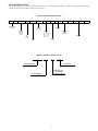
UNIT IDENTIFICATION
The unit is identified using a 16 digit model number structure. It is recommended providing the complete 16 digit model number when
ordering replacement parts to insure receiving the correct parts.
MODEL NUMBER NOMENCLATURE
1
2
3
4
5
6
7
8
9
10
11
12
13
14
15
16
2
5
V
N
A
0
3
6
A
0
0
3
0
0
0
0
Product Series
Heat Pump
Undefined
SEER
(20 SEER)
Product
Family
Variable
Speed
Available
Sizes
24 = 2--- Ton
36 = 3--- Ton
48 = 4--- Ton
60 = 5--- Ton
Tier
Infinity
Series
Available
Voltage
208/230--- 1
Undefined
Variation
A = Std
Major
Series
SERIAL NUMBER NOMENCLATURE
01
06
E
Week of Manufacture
00001
Serial Number
Manufacturing Site
E = Collierville TN
X = Monterrey Mexico
Year of Manufacture
2
SAFETY CONSIDERATIONS
Installation, service, and repair of these units should be attempted
only by trained service technicians familiar with standard service
instruction and training material.
All equipment should be installed in accordance with accepted
practices and unit Installation Instructions, and in compliance with
all national and local codes. Power should be turned off when
servicing or repairing electrical components. Extreme caution
should be observed when troubleshooting electrical components
with power on. Observe all warning notices posted on equipment
and in instructions or manuals.
WARNING
!
ELECTRICAL SHOCK HAZARD
Failure to follow this warning could result in personal
injury or death.
Before installing, modifying, or servicing system, main
electrical disconnect switch must be in the OFF position.
There may be more than 1 disconnect switch. Lock out and
tag switch with a suitable warning label.
!
WARNING
UNIT OPERATION AND SAFETY HAZARD
Failure to follow this warning could result in personal
injury or equipment damage.
Puronr (R--410A) systems operate at higher pressures than
standard R--22 systems. Do not use R--22 service equipment
or components on Puronr equipment. Ensure service
equipment is rated for Puronr.
Refrigeration systems contain refrigerant under pressure. Extreme
caution should be observed when handling refrigerants. Wear
safety glasses and gloves to prevent personal injury. During normal
system operations, some components are hot and can cause burns.
Rotating fan blades can cause personal injury. Appropriate safety
considerations are posted throughout this manual where potentially
dangerous techniques are addressed.
If you do not understand any of the warnings, contact your
product distributor for better interpretation of the warnings.
GENERAL INFORMATION
!
WARNING
ELECTRICAL HAZARD -- HIGH VOLTAGE!
Failure to follow this warning could result in personal injury
or death.
Electrical components may hold charge. DO NOT remove
control box cover for 2 minutes after power has been
removed from unit.
PRIOR TO TOUCHING ELECTRICAL COMPONENTS:
Verify less than 20 vdc voltage at inverter connections shown
on inverter cover.
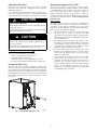
!
CAUTION
CUT HAZARD
Failure to follow this caution may result in personal injury.
The 25VNA Greenspeed Intelligence heat pump features a new
outdoor cabinet design that uses a four sided coil design to
minimize the unit foot print and provide the best heat exchange
taking full advantage of the latest variable speed technology. The
heart of the system is the Copeland variable speed compressor
powered through the use of the Emerson variable speed drive
(VSD) inverter control. Through the use of Puron refrigerant ,ECM
outdoor fan, Emerson VSD and Copeland variable speed
compressor along with the new outdoor cabinet the unit achieves a
Seasonal Energy Efficiency Ratio (SEER) up to 20.5 and up to 13
Heating Seasonal Performance Factor (HSPF).
To ensure all of the above technology provides the ultimate in
comfort it is combined with either the FE fan coil or Variable
Speed Gas furnace controlled with a two wire communication
Infinity User Interface (SYSTXCCUID01--V) or the Infinity Zone
User Interface (SYSTXCCUIZ01--V). Ensuring achievement of
comfort with the consciences of finger tip trouble shooting and
diagnostic capability.
Sheet metal parts may have sharp edges or burrs. Use care and
wear appropriate protective clothing and gloves when
handling parts.
3
ELECTRICAL
!
3. Reconnect leads and apply low--voltage power to contactor
coil. This may be done by leaving high--voltage power to
outdoor unit off and turning thermostat to cooling. Check
voltage at coil with voltmeter. Reading should be between
20v and 30v. Contactor should pull in if voltage is correct
and coil is good. If contactor does not pull in, replace
contactor.
4. With high--voltage power off and contacts pulled in, check
for continuity across contacts with ohmmeter. A very low or
0 resistance should be read. Higher readings could indicate
burned or pitted contacts which may cause future failures.
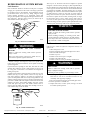
WARNING
ELECTRICAL SHOCK HAZARD
Failure to follow this warning could result in personal injury
or death.
Exercise extreme caution when working on any electrical
components. Shut off all power to system prior to
troubleshooting. Some troubleshooting techniques require
power to remain on. In these instances, exercise extreme
caution to avoid danger of electrical shock. ONLY TRAINED
SERVICE
PERSONNEL
SHOULD
PERFORM
ELECTRICAL TROUBLESHOOTING.
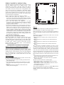
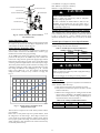
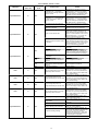
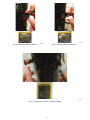
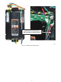
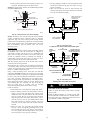
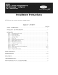
Parts Location
PRESSURE TRANSDUCER (SPT)
Aluminum Wire
!
ACCUMULATOR TUBE
SUCTION TUBE
CAUTION
SUCTION THERMISTOR (OST)
ACCUMULATOR
UNIT OPERATION AND SAFETY HAZARD
Failure to follow this caution may result in equipment
damage or improper operation.
Aluminum wire may be used in the branch circuit (such as
the circuit between the main and unit disconnect), but only
copper wire may be used between the unit disconnect and the
unit.
Whenever aluminum wire is used in branch circuit wiring with this
unit, adhere to the following recommendations.
Connections must be made in accordance with the National
Electrical Code (NEC), using connectors approved for aluminum
wire. The connectors must be UL approved (marked Al/Cu with
the UL symbol) for the application and wire size. The wire size
selected must have a current capacity not less than that of the
copper wire specified, and must not create a voltage drop between
service panel and unit in excess of 2 of unit rated voltage. To
prepare wire before installing connector, all aluminum wire must
be “brush--scratched” and coated with a corrosion inhibitor such as
Pentrox A. When it is suspected that connection will be exposed to
moisture, it is very important to cover entire connection completely
to prevent an electrochemical action that will cause connection to
fail very quickly. Do not reduce effective size of wire, such as
cutting off strands so that wire will fit a connector. Proper size
connectors should be used. Check all factory and field electrical
connections for tightness. This should also be done after unit has
reached operating temperatures, especially if aluminum conductors
are used.
Contactor
COMPRESSOR
REVERSING VALVE
SUCTION SERVICE VALVE
Type: 10k Ω negative temperature coefficient Suction Thermistor used
to control EXV
A11103
Fig. 1 – Suction Thermistor (OST) Attachment
(On Suction Tube)
This unit uses a 5 VDC output low pressure transducer that
provides a 0--5VDC data for interpretation by the control board a 0
to 200 psig range of pressure at the suction tube.
Signals used by control board for:
S
S
S
S
S
S
Low pressure cut--out
Loss of charge management,
Compressor overall envelope management
Oil circulation management
Lubrication management and
EXV control.
Type: 10K Ω negative temperature coefficient temperature sensor.
Therm--O--Disc part number HH79NZ092 used for EXV control
The contactor provides a means of applying power to unit using
low voltage (24v) from transformer in order to power contactor
coil. Depending on unit model, you may encounter single-- or
double--pole contactors. Exercise extreme caution when
troubleshooting as 1 side of line may be electrically energized. The
contactor coil is powered by 24vac. If contactor does not operate:
1. With power off, check whether contacts are free to move.
Check for severe burning or arcing on contact points.
2. With power off, use ohmmeter to check for continuity of
coil. Disconnect leads before checking. A low resistance
reading is normal. Do not look for a specific value, as
different part numbers will have different resistance values.
4
Electronic Expansion Valve
Motor Control Drive (Inverter):
Converts the sinusoidal AC input mains voltage into a
variable frequency AC output generated used PWM
modulation of the output.
S Drive adjusts the output voltage to run the compressor at
the correct speed at any load point in the envelope.
S The drive actively controls the motor current to insure
the proper torque is provided for the given loading
condition.
S The drive control algorithms insure the magnetic field set
up in the motor is synchronized with the rotor insuring
smooth efficiency operation.
S The drive actively controls the input current at heavy
loading conditions to insure the input power factor to the
drive is >0.95.
Compressor Brushless Permanent Magnet Motor (BPM):
S
The motor inductance reacts to the drive current and a
sinusoidal current is induced through the motor
windings.
S The sinusoidal current sets a rotating magnetic field, at
the frequency set by the drive.
S The magnets enable the motor to synchronize to that
frequency, set by the drive.
S Supplies the mechanical power afforded to it by the drive
voltage, current and frequency.
Motor Control Drive + BPM together:
S
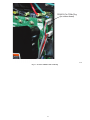
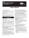
Fig. 2 – Electronic Expansion Valve (EXV)
An EXV is used for accurate refrigerant metering in the heating
mode. It enables the system to achieve high HSPF rating.
The outdoor board senses suction pressure and temperature to
control EXV movement.
The EXV has a stepper motor with 600 steps from fully open to
fully closed
Cooling
Valve is wide open
Heating
At start of each cycle, valve controls to a fixed position depending
on speed and ambient temperature for 120 seconds. This allows
the refrigerant system to stabilize. After this “pre--set” period,
control board controls valve as needed to control suction superheat
and/or compressor load.
Defrost
Valve is wide open
Controller
The variable speed Heat Pump (VS HP) controller is a serially
communicating device that receives capacity demands from the
Infinity User Interface and communicates corresponding speed
request to the Inverter Drive, which controls compressor to the
speed demanded.
The VS HP Control also controls the EXV to either provide
superheat or act as a load--shedding tool.
The VS HP Control also proactively tries to prevent fault trip
events by using sensors and Inverter feedback. Sensors include a
suction pressure transducer (SPT), an outdoor suction thermistor
(OST), the outdoor air thermistor (OAT), outdoor coil thermistor
(OCT), high pressure switch (HPS) etc.
Features:
— Serially Communicating
— 2 or 3 Wire
— DX+, DX-— Ground (optional)
— Capacity Feedback
— Ambient Optimized Speed Ranges
— Proactive Fault Prevention
— Automatic Load Shedding
— Heating Superheat Control with EXV
— Intelligent Defrost
— Low Ambient Cooling
— Hold at compressor speed on start--up
— User Interface holds demand to minimum for 5 minutes
S
S
S
S
Through the combination of the drive and motor, the
system is able to operate over a wide speed range.
The drive provides protection of the system to various
abnormal conditions including limiting the compressor
envelope of operation to appropriate boundaries.
Provides many pieces of system data as feedback to the
system controller.
Allows operation at least than full performance in case of
system faults or issues.
Crankcase Heater Operation
This unit has an internal crankcase heater that will be energized
during the off cycle and is intelligently demanded by the system to
prevent the compressor from being the coldest part of the system
thus enhancing the reliability. The crankcase heater will function
as needed any time the outdoor unit is powered. The indoor unit
and UI do not need to be installed for the crankcase heater to
operate properly.
NOTE: Contactor may close intermittently without the unit
starting. This is done to determine whether the control needs to
energize the crankcase heater. Closing the contactor powers the
inverter and allows the system to check compressor temperature.
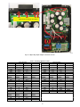
Outdoor Fan Motor Operation
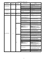
The outdoor unit control (Fig. 3) energizes outdoor fan anytime
compressor is operating, except for defrost and as needed during
low--ambient cooling operation. The outdoor fan remains
energized if a pressure switch opens or compressor scroll over
temperature should occur. This OD fan is an ECM motor which
operates at varying speeds depending on the ambient and the
demand.
Time Delays
The unit time delays include:
S Five minute time delay to start cooling or heating operation
when there is a call from the user interface. To bypass this
feature, momentarily short and release Forced Defrost pins.
S Five minute compressor re--cycle delay on return from a
brown--out condition.
5
Utility Interface With Infinity Control
The utility curtailment relay should be wired between the two
UTIL connections on the control board for this Infinity
Communicating System. This input allows a power utility device
to interrupt compressor operation during peak load periods. When
the utility sends a signal to shut the system down, the User
Interface will display, ”Curtailment Active”. See UI installation
instructions for setup details.
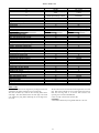
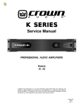
Communication and Status Function Lights
Infinity Control, Green Communications (COMM)Light
A green LED (COMM light) on the outdoor board (see Fig. 3)
indicates successful communication with the other system
products. The green LED will remain OFF until communication is
established. Once a valid command is received, the green LED will
turn ON continuously. If no communication is received within 2
minutes, the LED will be turned OFF until the next valid
communication.
Amber Status Light
Amber colored STATUS light indicates operation and error status.
See Table 5 and Table 6 for definitions.
S Two minute time delay to return to standby operation from last
valid communication.
S One minute time delay of outdoor fan at termination of cooling
mode when outdoor ambient is greater than or equal to 100_F
(37.8_C).
S Fifteen second delay at termination of defrost before the
auxiliary heat is de--energized.
1
BRN
RED
SEC1
SEC2
YEL
BLU
EXV
PWM2
CC
PWM1
PL4
PL3
SPT
HPS
PL11
CB
PL2
OST
RVS
PL1
PL6
INVERTER
This unit is capable of low ambient cooling down to 0°F (--17.8°C)
with Low Ambient enabled on the Infinity Control. A low
ambient kit is not required. The only accessory that may be
required is wind baffles in locations which are likely to experience
cross winds in excess of 5 miles an hour. This generally occurs
only on roof and open area applications. The Infinity Control
provides an automatic evaporator freeze thermostat. Low ambient
cooling must be enabled in the User Interface setup. Fan may not
begin to cycle until about 40°F (4.4°C) OAT. Fan will cycle based
on coil and outdoor air temperature.
Infinity controlled low ambient mode operates as follows:
S Fan is OFF when outdoor coil temperature is too low (+
55_F/12.7_C), the saturated suction pressure indicates a freezing
indoor coil or outdoor fan has been ON for 30 minutes. (Fan is
turned off to allow refrigerant system to stabilize.)
S Fan is ON when outdoor coil temperature is too high
(+80_F/26.7_C), the high side pressure is too high or if outdoor
fan has been OFF for 30 minutes. (Fan is turned on to allow
refrigerant system to stabilize)
S Low pressure indication by the suction pressure transducer is
ignored for first 3 minutes during low ambient start up. After 3
minutes, if low pressure trip occurs, then outdoor fan motor is
turned off for 10 minutes, with the compressor running. If
pressure condition is satisfied within 10 minutes then cooling
continues with the outdoor fan cycling per the coil temperature
routine listed above for the remainder of the cooling cycle. If the
suction pressure condition is not satisfied within 10 minutes, then
the normal trip response (shut down cooling operation and
generate LP trip error) will occur.
PL5
Infinity Controlled Low Ambient Cooling
OCT
OAT
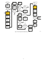
COMM STATUS
UTIL C LS Y O
A B C NO
USE
PL8
MODEL
J2
FORCED
DEFROST
A11139
Fig. 3 – Variable Speed Control Board
Defrost
This user interface (UI) offers 5 possible defrost interval times: 30,
60, 90, 120 minutes, or AUTO. The default is AUTO.
Defrost interval times: 30, 60, 90, and 120 minutes or AUTO are
selected by the Infinity Control User Interface (dip switches are not
used.)
AUTO defrost adjusts the defrost interval time based on the last
defrost time as follows:
S When defrost time <3 minutes, the next defrost interval=120
minutes.
S When defrost time 3--5 minutes, the next defrost interval=90
minutes.
S When defrost time 5--7 minutes, the next defrost interval=60
minutes.
S When defrost time >7 minutes, the next defrost interval=30
minutes.
The control board accumulates compressor run time. As the
accumulated run time approaches the selected defrost interval time,
the control board monitors the coil temperature sensor for a defrost
demand. If a defrost demand exists, a defrost cycle will be initiated
at the end of the selected time interval. A defrost demand exists
when the coil temperature is at or below 32_F (0_C) for 4 minutes
during the interval. If the coil temperature does not reach 32_F
(0_C) within the interval, the interval timer will be reset and start
over.
S Upon initial power up the first defrost interval is defaulted to 30
minutes. Remaining intervals are at selected times.
S Defrost is only allowed to occur below 50_F (10_C) outdoor
ambient temperature.
The defrost cycle is terminated as described below.
S When OAT is > 30°F (--1.1 °C), defrost terminates if outdoor
coil temperature (OCT) > 50°F (+10°C)
S When OAT is </= 30°F (--1.1°C), defrost terminates if outdoor
coil temperature (OCT) > 40 °F (+4.4°C)
S Or 10 minutes has passed.
At the defrost termination, the outdoor fan output (ODF) will turn
on 15 seconds before the reversing valve switching.
NOTE: Compressor speed during defrost varies based on outdoor
conditions.
6
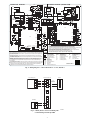
COMP
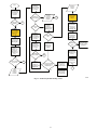
CONNECTION DIAGRAM
YEL
M
21
208/230 1Ø
POWER
SUPPLY
CHOKE
CHOKE
CONT
23
YEL
23
BLK
BRN
C C
EQUIP GND
INVERTER
GRN
BLK
11 21
L2
S
M
5
EXV
L1
COMP
BLK
11
T2
CONT
EQUIP
GND
CONTROL
BOARD
C
TRAN
CONT
5
T3
RED
BLK
23
CHOKE
INVERTER
YEL
23
L1
INVERTER
WHT
RED
GRN
CHOKE
YEL
230V 208V COM
BLK
COMPONENT ARRANGEMENT
CONT
T1
RED
CHOKE
WHT
C
T3
S
RED
BLK
TRAN 24V
T2
T1
RED
BRN
L2
SCHEMATIC DIAGRAM (LADDER FORM)
BLK
OFM
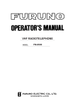
MODEL PLUG CHART
MODEL MODEL PIN RESISTANCE (K )
PLUG
SIZE
HK70EZ 1 - 4 (R1) 2 - 3 (R2)
5.1
11
001
24
5.1
002
18
36
5.1
003
24
48
5.1
004
33
60
230V
C
TRAN 24V
OFM
EXV
1
YEL
PL5
BLU
GRN/YEL
RED/WHT
BRN/YEL
TRAN
SEC1 SEC2
EXV
PWM2
PWM1
CC
PL5
1
BRN
RED
5
PL3
PWM2
HPS
PWM1
RVS
PL4
PL3
SPT
HPS
PL2
ORG
RVS
PL11
CB
OST
RED
BLK
WHT
GRN
PL1
5
PL1
BLK
RVS
BLK
PL6
INVERTER
BARE
RVS
OST
ORG
OCT
OAT
A B C NO
USE
J2
FORCED
DEFROST
PL8
MODEL
OAT
UTIL C LS Y O
CONT
BLK
OAT
1.
2.
3.
4.
LS
UNIT OPERATION
MODEL
J2
FORCED
DEFROST
LS
Compressor Furnished With Inherent Thermal Protection.
To Be Wired In Accordance With National Electric Code (N.E.C.) And Local Codes.
Use Copper Conductors Only. Use Conductors Suitable For At Least 70ºC (167ºF).
Two Wire A and B Required For Communication. Unit Contains 24 Volt Transformer To Power Control
Board. If Outdoor Unit Improperly Grounded, Connect Indoor Ground To “C” Terminal.
If Any Of The Original Wire, As Supplied, Must Be Replaced, Use The Same Or Equivalent Wire.
Check All Electrical Connections Inside Control Box For Tightness.
Do Not Attempt To Operate Unit Until Service Valves Have Been Opened.
Must Use With Infinity User Interface Listed In Pre-sale Literature Only.
HIGH PRESSURE SWITCH
INVERTER DRIVE
LIQUID LINE SOLENOID
THERMISTOR (OUTDOOR AIR)
THERMISTOR (COIL)
OUTDOOR FAN MOTOR
THERMISTOR (SUCTION)
HPS
INVERTER
LS
OAT
OCT
OFM
OST
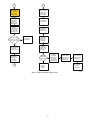
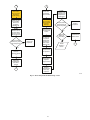
Furnace or Fan Coil
VS HP
No
Use
D
D
C
C
B
B
B
A
A
A
C
HUM
C
W
O
Y
R
OAT
C and D
not required on
VS Heat Pump
A12055
Fig. 5 – Infinity Furnace or Fan Coil Wiring with
Communicating Variable Speed HP
7
RVS
SPT
STATUS
TRAN
UTIL
REVERSING VALVE SOLENOID
SUCTION PRESSURE
TRANSDUCER
SYSTEM FUNCTION LIGHT
TRANSFORMER
UTILITY CURTAILMENT
338633-101 REV. A
Fig. 4 – Wiring Diagram — 25VNA Model sizes 2 -- 5 tons, 208/230--1
24vac C
OAT
NOTES:
This Control Board Contains A Five Minute Short Cycle Protector. A Five Minute Delay Will Occur Between Compressor Off/on
-LEGENDCycles. To Bypass Delay, Short Forced Defrost Pins For 1 Second Then Release. The Crankcase Heater Is Energized During
Off Cycle Below 75ºF As Needed.
FACTORY POWER WIRING
FIELD POWER WIRING
DEFROST TIME SELECTION - The Defrost Interval Time Can Be Field Selected, Dependent Upon Local Georgraphic
FACTORY CONTROL WIRING
Requirements. It Is Factory Set At 90 Minutes And Can Be Changed To Either 30, 60 Or 120 Minutes Via The User Interface.
FIELD CONTROL WIRING
User Interface Defaults to “AUTO”.
COMPONENT CONNECTION
DEFROST - Defrost Will Only Be Performed At Outdoor Temperatures Less Than 50ºF. Defrost Will Initiate When Time
JUNCTION
Selected Has Elapsed And The Coil Temperature Is Less Than 32ºF (+/-2ºF). It Will Terminate At 65ºF, 50ºF, or 45ºF (+/-5ºF),
FIELD SPLICE
As Needed Based On OAT. At Defrost Termination The Outdoor Fan Will Turn On 15 Seconds Before Switching The
CONTROL BOARD
CB
Reversing Valve..
CONTACTOR COIL
CC
FIELD INITIATED FORCED DEFROST - (Shown As Forced Defrost On Board) By Placing A Jumper Across The Forced Defrost
COMM SYSTEM COMMUNICATION
Terminals For 5 Seconds, Or Longer, And Then Removing The Jumper The Unit Will Initate A Defrost Cycle Regardless Of Coil
COMP COMPRESSOR
Temperature. The Defrost Cycle Will Terminate At 65ºF (+/-5ºF) If Coil Termperature Is Above 32ºF Or Outdoor Ambient
CONT CONTACTOR
ELECTRONIC EXPANSION VALVE
Temperature Is Above 50ºF, Defrost Mode Will Terminate After 30 Seconds Of Active Mode.
EXV
Humidifier
PL8
A BC NO
USE
BLK
5.
6.
7.
8.
User Interface (UI)
OCT
COMM STATUS
COMM STATUS
UTIL C LS Y O
PL6
OCT
CHOKE
OCT
BRN
BRN
CHOKE
OST
OST
SPT
INVERTER
BLU/PNK
BLU/PNK
RED
+
WHT
BLK
PL11
PL2
SPT
+
-
SPT
HPS
CC
HPS
PL4
CB
YEL
BLU
EXV
SEC1 SEC2
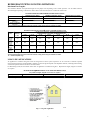
REFRIGERANT PIPING LENGTH LIMITATIONS
Maximum Line Lengths:
The maximum allowable total equivalent length for heat pumps varies depending on the vertical separation. See the tables below for
allowable lengths depending on whether the outdoor unit is on the same level, above or below the outdoor unit.
MAXIMUM LINE LENGTHS FOR HEAT PUMP APPLICATIONS
Units on equal level
MAXIMUM ACTUAL LENGTH
ft (m)
200 (61)
MAXIMUM EQUIVALENT LENGTH{
ft (m)
250 (76.2)
MAXIMUM VERTICAL SEPARATION ft (m)
N/A
200 (61)
250 (76.2)
200 (61)
Outdoor unit ABOVE
indoor unit
Outdoor unit BELOW
indoor unit
See Table ’Maximum Total Equivalent Length: Outdoor Unit BELOW Indoor Unit’
{ Total equivalent length accounts for losses due to elbows or fitting. See the Long Line Guideline for details.
Maximum Total Equivalent Length{ -- Outdoor Unit BELOW Indoor Unit
Size
Liquid Line
Diameter
w/ TXV
024
HP with
Puron
036
HP with
Puron
048
HP with
Puron
060
HP with
Puron
0--- 20
(0 --- 6.1)
HP with Puronr Refrigerant --- Maximum Total Equivalent Length{
Vertical Separation ft (m) Outdoor unit BELOW indoor unit;
21--- 30
31--- 40
41--- 50
51--- 60
61--- 70
(6.4 --- 9.1)
(9.4 --- 12.2)
(12.5 --- 15.2)
(15.5 --- 18.3)
(18.6 --- 21.3)
71--- 80
(21.6 --- 24.4)
3/8
250*
250*
250*
250*
250*
250*
250*
3//8
250*
250*
250*
250*
250*
250*
250*
3/8
250*
250*
250*
250*
230
160
--- ---
3/8
250*
225*
190
150
110
--- ---
--- ---
* Maximum actual length not to exceed 200 ft (61 m)
{ Total equivalent length accounts for losses due to elbows or fitting. See the Long Line Guideline for details.
--- --- = outside acceptable range
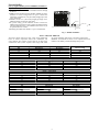
LONG LINE APPLICATIONS
An application is considered Long Line when the refrigerant level in the system requires the use of accessories to maintain acceptable
refrigerant management for systems reliability. Defining a system as long line depends on the liquid line diameter, actual length of the tubing,
and vertical separation between the indoor and outdoor units.
For Heat Pump systems, the chart below shows when an application is considered Long Line. Beyond these lengths, long line accessories
are required:
HP WITH PURONr REFRIGERANT LONG LINE DESCRIPTION ft (m)
Beyond these lengths, long line accessories are required
Liquid Line Size
Units On Same Level
Outdoor Below Indoor
Outdoor Above Indoor
3/8
80 (24.4)
20 (6.1) vertical or 80 (24.4) total
80 (24.4)
Note: See Long Line Guideline for details
A11265
Fig. 6 – Long Line Application
8
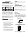
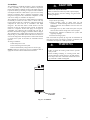
External Muffler
Factory Supplied Muffler (part # LM10KK003) Installation is
Required On Every Installation:
S A muffler is required to reduce noise transmitted to indoor through
the line set.
S Muffler must be installed outside the dwelling. Muffler can also be
installed in vertical configuration for space consideration
maintaining a minimum of 12 in (304.8 mm) straight pipe section
to the closest bend.
S Maintain at least 12 in. (304.8 mm) straight pipe length to the
muffler shell inlet and from the outlet stubs.
S To prevent rusting, provide sufficient clearance between the
muffler and the ground surface. Also, position the muffler such that
accidental abuse (such as by a weed trimmer, lawn mower etc.) of
the painted surface is avoided.
S Insulating the muffler with Armaflext tape is recommended.
EXTERIOR
WALL
MUFFLER
TO DWELLING
VAPOR LINE
A11543
Fig. 7 – Muffler Installation
Table 1—MIN/MAX AIRFLOW
The indoor airflow delivered by this system varies significantly
the system will deliver full capacity at all outdoor temperatures.
based on outdoor temperature, indoor unit combination, and
Minimum and maximum air flows can be adjusted from these
system demand. The air flows on these tables are for duct design
numbers in the Infinity Control Heat Pump Setup screen.
considerations. Duct systems capable of these ranges will ensure
Cooling --- Comfort Mode
Max Capacity
Min Capacity
Minimum Cooling
(Dehum or Zoning)
24
726
651
398
36
1168
651
398
48
1394
1186
693
60
1650
1186
693
Size
Cooling --- Efficiency Mode
Size
Max Capacity
Min Capacity
24
949
830
36
1334
830
48
1593
1355
60
1885
1355
Heating --- Comfort Mode
Size
Max Capacity
Min Capacity
24
698
440
36
1140
451
48
1354
751
60
1354
751
Heating --- Efficiency Mode
Size
Max Capacity
Min Capacity
24
900
750
36
1350
518
48
1600
890
60
1750
901
9
TROUBLESHOOTING
Control Fault
Systems Communication Failure
If communication with the Infinity control is lost with the User
Interface (UI), the control will flash the appropriate fault code (see
Table 5 and Table 6). Check the wiring to the User Interface and
the indoor and outdoor units and power.
Model Plug
Each control board contains a model plug. The correct model plug
must be installed for the system to operate properly (see Table 2).
Table 2—Model Plug Information
PIN RESISTANCE
(K--- ohms)
MODEL
NUMBER
MODEL PLUG
NUMBER
Pins 1--- 4
Pins 2--- 3
25VNA024
HK70EZ001
5.1K
11K
25VNA036
HK70EZ002
5.1K
18K
25VNA048
HK70EZ003
5.1K
24K
25VNA060
HK70EZ004
5.1K
33K
The model plug is used to identify the type and size of unit to the
control.
On new units, the model and serial numbers are input into the
board’s memory at the factory. If a model plug is lost or missing at
initial installation, the unit will operate according to the
information input at the factory and the appropriate error code will
flash temporarily. An RCD replacement board contains no model
and serial information. If the factory control board fails, the model
plug must be transferred from the original board to the replacement
board for the unit to operate.
NOTE: The model plug takes priority over factory model
information input at the factory. If the model plug is removed after
initial power up, the unit will operate according to the last valid
model plug installed, and flash the appropriate fault code
temporarily.
If the outdoor unit control board has failed, the control will flash
the appropriate fault code. The control board should be replaced.
If the sensors are out of range, the control will flash the appropriate
fault code.
The thermistor comparisons are not performed during low ambient
cooling or defrost operation.
Failed Thermistor Default Operation
Factory defaults have been provided in the event of failure of
outdoor air thermistor (OAT) and/or outdoor coil thermistor
(OCT).
If the OAT sensor should fail, low ambient cooling will not be
allowed and the one--minute outdoor fan off delay will not occur.
Defrost will be initiated based on coil temperature and time.
If the OCT sensor should fail, low ambient cooling will not be
allowed. Defrost will occur at each time interval during heating
operation, but will terminate after 5 minutes.
If there is a thermistor out--of--range error, defrost will occur at
each time interval during heating operation, but will terminate after
5 minutes.
Count the number of short and long flashes to determine the
appropriate flash code.
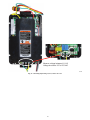
Outdoor Coil Thermistor
The outdoor coil thermistor is a 10Kohm resistor used for multiple
system operations. It provides the coil/liquid line temperature to
the heat pump board and user interface. Low ambient operation,
defrost initiation, defrost termination and assistance with OAT
temperature measurement of some of the functions. The sensor
must be securely mounted to the tube connecting the EXV and
distributor. See Fig.9 for proper placement.
OAT Thermistor must be
locked in place with
spherical nib end facing
towards the front of the
control box
Pressure Switch Protection
The outdoor unit is equipped with high pressure switch. If the
control senses the opening of a high pressure switch, it will
respond as follows:
1. De--energize the contactor.
2. Keep the outdoor fan operating for 15 minutes.
3. Display the appropriate fault code (see Table 5 and Table 6).
4. After a 15 minute delay, if there is a call for cooling or heating and HPS is reset, the contactor is energized.
5. If HPS has not closed after a 15 minute delay, the outdoor
fan is turned off. If the open switch closes anytime after the
15 minute delay, then resume operation with a call for cooling or heating at a temporary reduced capacity.
6. If HPS trips 3 consecutive cycles, the unit operation is
locked out for 4 hours.
7. In the event of a high--pressure switch trip or high--pressure
lockout, check the refrigerant charge, outdoor fan operation,
and outdoor coil (in cooling) for airflow restrictions, or indoor airflow in heating.
8. In the event of a low--pressure trip or low--pressure lockout,
check the refrigerant charge and indoor airflow (cooling)
and outdoor fan operation and outdoor coil in heating.
A11142
Fig. 8 – OAT Thermistor Location (Bottom of Control Box)
OCT SENSOR
LOCATION
A11143
Fig. 9 – Outdoor Coil Thermistor (OCT) Attachment
(On Distributor Tube)
10
PRESSURE TRANSDUCER (SPT)
ACCUMULATOR TUBE
Cool: PSUCT < 55 psig (for 3 minutes)
Heat: PSUCT < 23 psig (for 3 minutes)
PSUCT < 13 psig (instantaneous)
!
SUCTION TUBE
COMPRESSOR
SUCTION THERMISTOR (OST)
CAUTION
UNIT DAMAGE HAZARD
Failure to follow this caution may result in equipment
damage or improper operation.
ACCUMULATOR
In order to minimize the ambient influence, make sure the
thermistor curved surface hugs the pipe surface and is
secured tight using the wire tie fished through the original
slot insulating polymer body.
REVERSING VALVE
Variable Speed Compressor Sensor Output Terminals
SUCTION SERVICE VALVE
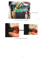
A11103
Fig. 10 – Suction Thermistor (OST) Attachment
(On Suction Tube)
Suction Thermistor (OST)
Suction Thermistor is used for assisting in EXV control and must
be secured on the suction tube and aligned longitudinally to the
vertical surface of the tube axis (see Fig. 10).
This compressor has a motor thermistor and a scroll thermistor.
Correct resistance between scroll thermistor terminal and common
is 10k at 77_F (25_C). Correct resistance between motor
thermistor terminal and common is 5k at 77_F (25_C). See Table
7.
Variable Speed Compressor Power Input Terminals
This compressor operates with a 3--phase variable frequency PWM
variable voltage to the three fusite terminals.
Suction Pressure Transducer (SPT)
Table 3—Variable Speed Compressor Resistances
(winding resistance at 70_F 20_F)
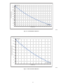
If the accuracy of the transducer is questioned, the technician can
check it while it is attached to the VSHP board. Connect a gage
manifold to the suction valve gage port fitting.
At the VSHP board, with the wire harness receptacle exposing a
portion of the three pins on the VSHP board, a DC voltmeter can
read the DC voltage between ground and supply (input) terminal.
Ensure that the input voltage is 5 VDC. Next, read the DC voltage
across the ground and output terminal. Record the output voltage.
The suction pressure that the pressure transducer is reading can be
calculated by taking the output voltage and subtracting 0.5 from it
then taking that difference and multiplying it by 50. Pressure
(psig) = 50.0 x (DCV out -- 0.5). For example, if the measured
voltage is 3.0 VDC: 50 X (3.0 -- 0.5) -- 50 X 2.5 = 125 psig. See
Fig. 11.
WINDING
25VNA024
25VNA036
25VNA048
25VNA060
Between terminals
T1, T2, and T3
.681
.203
Between terminal &
ground
>1 mega OHM
>1 mega OHM
!
CAUTION
UNIT DAMAGE HAZARD
Failure to follow this caution may result in equipment damage
and/or improper operation.
Do not use Meggar for measuring the winding resistance.
6
ECM Fan Motor
5
If verification of proper operation is required for the ECM motor
used in this unit, follow these steps:
1. Verify that the 230v input to the transformer is present.
2. Verify that the control board is powered 18 volts to 30 volts
from the transformer.
3. With the UI in charging mode in cooling, measure the DC
voltage between the PWM 1 and PWM 2 terminals on the
outdoor control board. The DC voltage and PWM (optional) measured must be as shown in Table 4.
Output Voltage (V)
4
3
2
1
Table 4—DC Voltage and PWM Measurement
0
0
25
50
75
100
125
150
175
200
225
Pressure - Sealed Gauge (psi)
A12035
Fig. 11 – Suction Pressure Transducer (SPT)
Output Funtion Graph
This can then be compared to the actual suction pressure from the
gage manifold.
In the event of a low pressure trip or low pressure lockout , check
the refrigerant for an under charge. If the charge is found to be
correct, check for low indoor airflow in cooling and the outdoor
fan for proper operation in heating and outdoor coil in heating for
airflow restrictions. Keep in mind that the outdoor fan motor may
run normally until it heats up.
11
Unit Size
Voltage
PWM
024, 036
8.9 VDC
52
048, 060
11.1 VDC
84
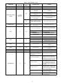
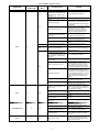
Table 5—Fault Codes
FAULT DESCRIPTION SENT TO UI
--- ----- ----- ---
FLASH CODE (AMBER LED)
Standby
Variable Capacity or Emergency
Mode
Variable Speed Range Cutback
Communications Loss
Invalid Model
High Pressure Switch Open
Low Pressure Trip
Control Fault
Brownout
Lost Inverter Communications
230VAC Dropout---Reset Event
Outdoor Air Temp Sensor Fault
Suction Temp Sensor Fault
Coil Temp Sensor Fault
OAT ---OCT Thermistor Out of range
Suction Pressure Sensor Fault
OAT ---OST Thermistor Out of range
Compressor Scroll Temp Out of Range
Compressor Sump Heating Active
Inverter / Compressor Internal Fault
Compressor Motor Temp Out of Range
Suction Over Temperature
Inverter Temp Out of Range Event
Inverter Over Current
Compressor No---Pump Event
Suction Over Temp Lockout
Low Pressure Lockout for 4 hours
High Pressure Lockout for 4 hours
Compressor Temp Lockout
Compressor Temp Sensor Fault
Inverter Temp Lockout
Inverter VDC ---Out Over Voltage
Inverter VDC ---Out Under Voltage
230VAC Under Voltage
230VAC Over Voltage
High Current Lockout
VDC Under Voltage Lockout
VDC Over Voltage Lockout
High Torque Event
High Torque Lockout
--- ---
16
25
31
32
45
46
48
49
53
54
55
56
57
58
59
68
69
71
72
75
77
79
82
83
84
85
86
88
91
92
93
94
95
96
97
98
99
OFF
RESET TIME (minutes)
ON, no flash
1, pause
1 (2 sec ON), longer pause (1
second OFF)
NA
NA
15
15
NA
Revert to 5 min cycle delay
Revert to 5 min cycle delay
Revert to 5 min cycle delay
NA
15
NA
NA
15
5
15
2 HOURS
15
15
15
15
15
15
4 Hours
4 HOURS
4 HOURS
4 HOURS
15
4 HOURS
15
15
15
15
2 HOURS
2 HOURS
2 HOURS
10
2 HOURS
NA
Status Codes
Most system problems can be diagnosed by reading the status code
as flashed by the amber status light on the control board.
The codes are flashed by a series of short and long flashes of the
status light. The short flashes indicate the first digit in the status
code, followed by long flashes indicating the second digit of the
error code.
The short flash is 0.25 seconds ON and the long flash is 1.0 second
ON. Time between flashes is 0.25 seconds. Time between short
flash and first long flash is 1.0 second. Time between code
repeating is 2.5 seconds with LED OFF.
Codes are easily read from user interface (UI)
EXAMPLE:
3 short flashes followed by 2 long flashes indicates a 32 code.
12
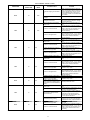
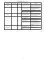
Table 6—25VNA EVENT / FAULT
OPERATION
FLASH CODE
(Amber LED)
Heat or Cool
Mode
Possible Causes
ACTION
Standby/Charging
ON, no flash
--- --- ---
--- --- ---
--- --- ---
Variable Capacity
1, pause
--- --- ---
--- --- ---
--- --- ---
Pressure Trip Cutback: 2 or more
High Pressure Trips occurred in
past 2 hours
System will self ---mitigate, persistent conditions will lead to lockout (refer to Error
Code 84)
High Load Cut back: 2 or more
Torque Limit Trips occurred in the
past 2 hours
System will try to self ---mitigate, persistent conditions will lead to lockout (refer
to Error Code 99)
Flank Loading Cutback: Flank Load
is too high, ODU raising speed
(shrinking capacity range) to improve reliability
System will try to self ---mitigate, persistent conditions will lead to lockout (refer
to Error Code 99)
Heat
Oil Circulation cutback: Suction
Pressure too high for current compressor speed; ODU reducing
speed to improve oil circulation
check for Indoor airflow restrictions
Both
Regular T ---Stat used in Emergency
mode: Nominal Capacity only (fixed
speed operation)
install Infinity User Interface
Loose wire or shorted leads
Verify communications wiring (ABCD);
check for loose connection, stripped
wires, short to ground or short between
wires
Wrong Model Plug Installed
Verify correct model plug installed
Damaged Model Plug
Check model plug for corrosion or
breakage; replace if necessary
Data Bus locked up by power loss,
brownout or glitch
Cycle Power to system
Both
Variable Capacity (Range
Cutback)
Emergency Mode
Event
Event
1 (1 sec ON),
longer pause (2
second OFF)
Continuous Flash
16
Both
25
Both
Damaged ODU control
Replace ODU control
Wrong Model Plug Installed
Verify correct model plug installed
Damaged Model Plug
Check model plug for corrosion or
breakage; replace if necessary
Damaged ODU control
Replace ODU control
Event
31
Both
High Pressure Event
System will self ---mitigate, persistent conditions will lead to lockout (refer to Error
Code 84)
Event
32
Both
Low Pressure Event
System will self ---mitigate, persistent conditions will lead to lockout (refer to Error
Code 83)
System Malfunction
45
Both
Damaged ODU control
Replace ODU control
Event
46
Both
low line voltages
if persistent contact power provider
Loose or disconnected harness (CC
@ HP control, CC @ contactor, INVERTER @ HP control, INVERTER
@ inverter drive)
Loose wire or shorted leads
Contactor not pulled in
System Malfunction
48
Both
Damaged Contactor Coil
Damaged ODU Control
Possible damage to Inverter Drive
13
Verify good harness connection
Verify communications wiring (”Inverter”
harness); check for loose connection,
stripped wires, short to ground or short
between wires; confirm good connection
is made at control board and at Inverter
Verify contactor harness from ODU control (”CC” harness); check for loose connection, stripped wires, short to ground
or short between wires; confirm good
connection is made at control board and
at contactor
if wiring is ok measure across the contactor coil for 18VAC --- 32VAC; if voltage
is present measure across contactor terminals 21 & 23 for line voltage if absent
then contactor is damaged
confirm ~ 5VDC on pins 3 & 4 of ”Inverter” pin out connection on ODU control if
absent board is damaged
Change out ODU control before Inverter
Drive; if this does not help then change
out the Inverter drive
25VNA EVENT / FAULT (CONT.)
OPERATION
Event
FLASH CODE
(Amber LED)
Heat or Cool
Mode
49
Both
Possible Causes
ACTION
Contactor dropping out momentarily
Verify contactor harness from ODU control (”CC” harness); check for loose connection, stripped wires, short to ground
or short between wires; confirm good
connection is made at control board and
at contactor
Voltage glitches and low line
voltages
if persistent contact power provider
Damaged Inverter Drive
Sensor Harness not connected to
ODU control
Broken or loose harness wire
Fault
53
Both
Broken or Damaged Sensor
Hardware damage to ODU control
Sensor Harness not connected to
ODU control
Broken or loose harness wire
Fault
54
Both
Suction Thermistor not properly attached or in wrong location
Broken or Damaged Sensor
Hardware damage to ODU control
Sensor Harness not connected to
ODU control
Broken or loose harness wire
Fault
55
Both
Coil Thermistor not properly attached or in wrong location
Broken or Damaged Sensor
Event
56
Both
Hardware damage to ODU control
Coil Thermistor not properly attached or in wrong location
Outdoor Ambient Temperature
sensor improperly installed (sensor
body may be in contact with sheet
metal)
Sensor Harness not connected to
ODU control
Broken or loose harness wire
Fault
57
Both
Electrical short destroyed Transducer electronics
Heat damage during brazing
Suction Thermistor not properly attached or in wrong location
Event
58
Both
Broken or loose harness wire
14
Change out ODU control before Inverter
Drive; if this does not help then change
out the Inverter drive
Ensure plug is connected to ODU control
Check harness for continuity; resistance
should measure 10 k at
77 +/ --- 20o F.
Refer to thermistor 10 k thermistor curve.
If bad, replace OAT/OCT thermistor
sensor assembly
Check harness for continuity; resistance
should measure 10 k at
77 +/ --- 20o F.
Refer to thermistor 10 k thermistor curve.
If bad, replace OAT/OCT thermistor
sensor assembly
Replace ODU control
Ensure plug is connected to ODU control
Check harness for continuity; resistance
should measure 10 k at
77 +/ --- 20o F.
Refer to thermistor 10 k thermistor curve.
If bad, replace OST sensor
Ensure Sensor is properly attached to
the accumulator entry ---tube
Check harness for continuity; resistance
should measure 10 k at
77 +/ --- 20o F.
Refer to thermistor 10 k thermistor curve.
If bad, replace OST sensor
Replace ODU control
Ensure plug is connected to ODU control
Check harness for continuity; resistance
should measure 10 k at
77 +/ --- 20o F.
Refer to thermistor 10 k thermistor curve.
If bad, replace OAT/OCT thermistor
sensor assembly
Ensure Sensor is properly clipped to the
distributor entry ---tube
Check harness for continuity; resistance
should measure 10 k at
77 +/ --- 20o F.
Refer to thermistor 10 k thermistor curve.
If bad, replace OAT/OCT thermistor
sensor assembly
Replace ODU control
Ensure Sensor is properly clipped to the
distributor entry ---tube
Properly install OAT sensor
Ensure plug is connected to ODU control
Check harness for stripped wires, shot to
ground or short between wires.
Compare transducer voltage reading to
gauge reading at service valve (see
Transducer Output Function graph);
Check system for electrical shorts and
correct; replace transducer.
Compare transducer reading to gauge
reading at service valve (see transducer
measurement chart); replace transducer
Ensure plug is properly attached to suction tube
Check harness for continuity; resistance
should measure 10 k at
77 +/ --- 20o F.
Refer to thermistor 10 k thermistor curve.
If bad, replace OST thermistor sensor
assembly
25VNA EVENT / FAULT (CONT.)
OPERATION
FLASH CODE
(Amber LED)
Event
58
Heat or Cool
Mode
Both
Possible Causes
Outdoor Air Thermistor Issue
Outside Normal Operating Range
(e.g. improper load calculation, system match issue, outside cooling
range etc)
Service Valve left closed (Liquid or
Vapor)
Undercharged System
Cool
Indoor Airflow too low or off
Restriction in Filter Drier plus Long
Line Application and filter drier on
Indoor Unit
Restriction due to debris
Restriction in Circuits or Tubing
Event
59
Both
Restriction in Filter Drier plus filter
drier on Outdoor Unit
Both
Expansion Orifice Restriction
Outside Normal Operating Range
(e.g. improper load calculation, system match issue, outside heating
range etc)
Service Valve left closed (Liquid
Service Valve)
Outdoor Airflow too low or off
Heat
Undercharged System
Reversing Valve Bypass
Restriction due to debris
Loss of power while EXV is open
leading to charge migration to compressor sump
Event
68
Both
EXV harness not connected to ODU
control
EXV coil not connected to EXV
TXV failed open
Inverter PFC Thermistor sensor
failed open
Noisy Line Voltage
Short Circuit in system
System Malfunction
69
Both
Compressor Winding Damage
Inverter Damaged
Event
71
Cool
Shorted sensor circuit
15
ACTION
See Error 53 and\or Error 56
Consult Application Guidelines
Ensure Service Valves are open
Check system subcooling to determine
charge status, if low add charge using
Charging Mode (follow proper charging
procedures)
Check Indoor for clogging (ice or debris)
and clean or de ---ice if necessary;
Troubleshoot Indoor fan motor and
make sure it is working; follow Indoor
Airflow troubleshooting instruction
Clean System (refer to application
guideline) and replace filter drier
Clean System (refer to application
guideline) and replace filter drier
Check kinks and straighten or replace
circuits
Clean System (refer to application
guideline) and replace filter drier
If short lineset (less than 15 ft)
Troubleshoot TXV (see guide below); replace if necessary
Troubleshoot EXV (see guide below)
Consult Application Guidelines
Ensure Liquid Service Valve is open
Check Outdoor for clogging (ice or
debris) and clean or de ---ice if necessary; Troubleshoot Outdoor fan motor
and make sure it is working; follow Outdoor Airflow troubleshooting instruction
Check charge in cooling (if in Cooling
Charge Mode Ambient Range), if low
add charge using Charging Mode (follow
proper charging procedures); if out side
cooling charge mode range, pull out
charge, weigh in using heating charge
mode
Reversing Valve Stuck halfway;
troubleshoot reversing valve
Clean System (refer to application
guideline) and replace filter drier
Nothing; system is warming up compressor sump temperature. Might take
up to 2 hours thus secondary heat might
be requested if necessary.
Check harness connection to ODU control
Check EXV coil and ensure it is well
seated
Check TXV operation and replace if necessary
Replace Inverter
Check line wiring and ensure proper
contacts (disconnects etc)
Check for system short circuit (loose
wire, damaged contacts etc)
Check compressor winding resistances;
See Compressor Troubleshooting
Check for system short circuit (loose
wire, damaged contacts etc); Replace
Inverter
Troubleshoot the compressor motor
thermistor. Compressor sensor fusite
should measure 5 kohm between motor
and common terminals.
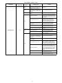
25VNA EVENT / FAULT (CONT.)
OPERATION
Event
FLASH CODE
(Amber LED)
72
Heat or Cool
Mode
Cool
Possible Causes
High Suction Gas Temperature
Outdoor Airflow too low or off
Event
75
Both
Blocked Inverter Heat Exchanger
(fins)
Application violates guideline
Event
77
Both
High Current Spikes in current
measured by the Inverter drive
Inverter Output to Compressor
leads miswired leading to compressor running backwards
Inverter Output to Compressor
leads not attached
Event
79
Both
Reversing Valve Bypass
Compressor Winding damage
System Malfunction
82
Cool
Overcharge, Attic run lineset and
High Load conditions
Outside Normal Operating Range
(e.g. improper load calculation, system match issue, outside cooling
range etc)
16
ACTION
System will try to ride through current
spikes and self ---recover in trip condition;
persistent over current trips will lead to
Error 82 ”Suction Over Temp Lockout”
(Refer to Error 82 troubleshooting)
Check ODU coil for clogging (ice or
debris) and clean if necessary;
Troubleshoot ODU fan motor and make
sure it is working
Check Inverter fins for debris and clean if
necessary
Consult Application Guideline for compliance
System will try to ride through current
spikes and self ---recover in trip condition;
persistent over current trips will lead to
Error 95 ”High Current Lockout” (Refer
to Error 95 troubleshooting)
check wiring at Inverter outputs
check wiring at Inverter outputs
Reversing Valve Stuck halfway;
troubleshoot reversing valve
Troubleshoot compressor windings. For
the 2 and 3T the resistance should be
.681 ohm and for 4 and 5T the resistance should be .203 ohm at 70F
+/ ---20F. See compressor troubleshooting guidelines. If confirmed replace
compressor
Verify charge by putting in cooling charging mode
Consult Application Guidelines
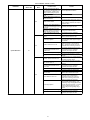
25VNA EVENT / FAULT (CONT.)
OPERATION
FLASH CODE
(Amber LED)
Heat or Cool
Mode
Cool
Cool
Cool
Possible Causes
Cooling in Low Ambient region (55
° F and below) with ”Low Ambient
Cooling Control” disabled
Outside Normal Operating Range
(e.g. improper load calculation, system match issue, outside cooling
range etc)
Service Valve left closed (Liquid or
Vapor)
Undercharged System
Indoor Airflow too low or off
Cool
Restriction in Filter Drier plus Long
Line Application and filter drier on
Indoor Unit
Restriction due to debris
Restriction in Circuits or Tubing
System Malfunction
Restriction in Filter Drier plus filter
drier on Outdoor Unit
83
Both
Expansion Orifice Restriction
Outside Normal Operating Range
(e.g. improper load calculation, system match issue, outside heating
range etc)
Service Valve left closed (Liquid
Service Valve)
Outdoor Airflow too low or off
Heat
Undercharged System
Reversing Valve Bypass
Restriction due to debris
17
ACTION
Enable ”Low Ambient Cooling” via user
interface
Consult Application Guidelines
Ensure Service Valves are open
Check system subcooling to determine
charge status, if low add charge using
Charging Mode (follow proper charging
procedures)
Check Indoor for clogging (ice or debris)
and clean or de ---ice if necessary;
Troubleshoot Indoor fan motor and
make sure it is working; follow Indoor
Airflow troubleshooting instruction
Clean System (refer to application
guideline) and replace filter drier
Clean System (refer to application
guideline) and replace filter drier
Check kinks and straighten or replace
circuits
Clean System (refer to application
guideline) and replace filter drier
If short lineset (less than 15 ft)
Troubleshoot TXV (see guide below); replace if necessary
Troubleshoot EXV (see guide below)
Consult Application Guidelines
Ensure Liquid Service Valve is open
Check Outdoor for clogging (ice or
debris) and clean or de ---ice if necessary; Troubleshoot Outdoor fan motor
and make sure it is working; follow Outdoor Airflow troubleshooting instruction
Check charge in cooling (if in Cooling
Charge Mode Ambient Range), if low
add charge using Charging Mode (follow
proper charging procedures); if outside
cooling charge mode range, pull out
charge, weigh in using heating charge
mode
Reversing Valve Stuck halfway;
troubleshoot reversing valve
Clean System (refer to application
guideline) and replace filter drier
25VNA EVENT / FAULT (CONT.)
OPERATION
FLASH CODE
(Amber LED)
Heat or Cool
Mode
Possible Causes
Outside Normal Operating Range
(e.g. improper load calculation, system match issue, outside cooling
range, outside heating range etc)
loose High Pressure Switch harness
leads
Pressure Switch disconnected from
ODU Control Board
Both
Faulty Pressure Switch
Restriction due to debris leading to
Overcharge when charging in Cooling mode
Restriction in EXV plus Long Line
Application leading to Overcharge
when charging in Cooling mode
None condensible leading to high
load
Service Valve left closed (Liquid or
Vapor)
Overcharged System
Cool
System Malfunction
Outdoor Airflow too low or off
Restriction in Filter Drier plus Long
Line Application and filter drier on
Outdoor Unit
Restriction in EXV plus Overcharge
84
Restriction in Circuits or Tubing
Electric Heater plus Heat pump application: Electric Heater stuck on
Furnace plus Heat pump application: Furnace stuck on
Restriction in Filter Drier plus Long
Line Application and filter drier on
Indoor Unit
Expansion Orifice Restriction
Service Valve left closed (Vapor
Service Valve)
Heat
Indoor Airflow too low or off
Overcharged System
Reversing Valve Stuck in Cooling
Restriction due to debris
18
ACTION
Consult Application Guidelines
Check HPS harness
Check HPS connection on ODU control
Check Discharge pressure with gauge, if
less than 610 +/ --- 20 psig and switch is
open (measure resistance) then replace
pressure switch
Clean System (refer to application
guideline) and replace filter drier
If long line, troubleshoot EXV
Clean System (refer to application
guideline) and replace filter drier
Ensure Service Valves are open
Check system charge using Cooling
Charging Mode (follow proper charging
procedures)
Check Outdoor Coil for clogging (ice or
debris) and clean or de ---ice if necessary; Troubleshoot Outdoor fan motor
and make sure it is working; follow Outdoor Airflow troubleshooting instruction
Clean System (refer to application
guideline) and replace filter drier
troubleshoot EXV
Check kinks and straighten or replace
circuits
If User Interface is not requesting Electric
Heat check for heater relays, if on
troubleshoot Electric Heater
If not in Defrost and Furnace is running
same time as heat pump, troubleshoot
Furnace
Clean System (refer to application
guideline) and replace filter drier
Troubleshoot TXV (see guide below)
Troubleshoot EXV (see guide below)
Ensure Vapor Service Valve is open
Check Indoor for clogging (ice or debris)
and clean or de ---ice if necessary;
Troubleshoot Indoor fan motor and
make sure it is working; follow Indoor
Airflow troubleshooting instruction
Check charge in cooling (if in Cooling
Charge Mode Ambient Range), if low
add charge using Charging Mode (follow
proper charging procedures); if out side
cooling charge mode range, pull out
charge, weigh in using heating charge
mode
troubleshoot reversing valve
Clean System (refer to application
guideline) and replace filter drier
25VNA EVENT / FAULT (CONT.)
OPERATION
FLASH CODE
(Amber LED)
Heat or Cool
Mode
Possible Causes
Multiple Error 59 --- ”Compressor
Scroll Temp Out of Range” within two
hours of run time
System Malfunction
85
Both
Multiple Error 71 --- ”Compressor Motor Temp Out of Range” within two
hours of run time
Sensor Harness not connected to Inverter Drive control
Sensor plug not properly sited or not
attached to compressor
System Malfunction
86
Both
Broken or loose harness wire
Failed Open/Close Compressor Internal Thermistor
Blocked Inverter Heat Exchanger (fins)
Both
System Malfunction
88
Cool
Heat
Both
Outdoor Airflow too low or off
Outdoor Unit airflow blocked (improper installation)
Outside Normal Operating Range (e.g.
outside cooling ambient temperature
range etc)
Outside Normal Operating Range (e.g.
outside heating ambient temperature
range etc)
Inverter internal damage
Event
91
Both
High DC Voltage spikes in DC voltage
measured by the Inverter drive
Event
92
Both
Low DC Voltage dropouts in DC
voltage measured by the Inverter drive
Event
93
Both
Low AC Voltage dropouts in AC
voltage measured by the Inverter drive
Event
94
Both
High AC Voltage spikes in AC voltage
measured by the Inverter drive
High supply line voltage (> 257 VAC)
Stormy weather causing intermittent
voltage spikes
System Malfunction
95
Both
Loose wire in control box area
Ground lead from Compressor attached to winding power connection
Compressor Winding damage
Inverter internal damage
19
ACTION
System will try to ride through current
spikes and self ---recover in trip condition;
persistent Error 59 --- ”Compressor Scroll
Temp Out of Range” trips will lead to Error
88; (Refer to Error 59 troubleshooting)
System will try to ride through current
spikes and self ---recover in trip condition;
persistent Error 71 --- ”Compressor Motor
Temp Out of Range” trips will lead to Error
88; (Refer to Error 71 troubleshooting)
Ensure plug is connected to Inverter Drive
control
Reattach sensor plug to compressor
Check harness for continuity; on the
sensor fusite resistance should be in 10
kOhm between scroll and common terminals and 5 kOhm between motor and common terminals at 70 +/ --- 20 F. See compressor troubleshooting guidelines
Check harness for continuity; on the
sensor fusite resistance should be in 10
kOhm between scroll and common terminals and 5 kOhm between motor and common terminals at 70 +/ --- 20 F. See compressor troubleshooting guidelines
Check Inverter fins for debris and clean if
necessary
Check Evaporator (IDU in cooling, ODU in
heating) for clogging (ice or debris) and
clean if necessary; Troubleshoot Evaporator fan motor and make sure it is working
Consult Application Guidelines
Consult Application Guidelines
Consult Application Guidelines
Replace Inverter
System will try to ride through voltage
spikes and self ---recover in trip condition;
persistent over current trips will lead to Error 97 ”High Voltage Lockout” (Refer to Error 97 troubleshooting)
System will try to ride through voltage dropouts and self ---recover in trip condition;
persistent over current trips will lead to Error 96 ”Low Voltage Lockout” (Refer to Error 96 troubleshooting)
System will try to ride through voltage dropouts and self ---recover in trip condition;
persistent over current trips will lead to Error 96 ”Low Voltage Lockout” (Refer to Error 96 troubleshooting)
System will try to ride through voltage
spikes and self ---recover in trip condition;
persistent over current trips will lead to Error 97 ”High Voltage Lockout” (Refer to Error 97 troubleshooting)
Check supply voltage to Outdoor Unit; if
high contact utility provider
When adverse weather subsides unit
should self ---recover; cycle ODU power if
necessary
Check for loose wire in ODU
Ensure compressor ground and other
leads are correctly installed
Troubleshoot compressor windings. For
the 2 and 3T the resistance should be .681
ohm and for 4 and 5T the resistance
should be .203 ohm at 70F +/ ---20F. See
compressor troubleshooting guidelines. If
confirmed replace compressor
Replace Inverter
25VNA EVENT / FAULT (CONT.)
OPERATION
FLASH CODE
(Amber LED)
Heat or Cool
Mode
Possible Causes
Low supply line voltage (< 180 VAC)
System Malfunction
96
Both
Stormy weather causing intermittent
voltage dropouts
Loose wire in control box area
Inverter internal damage
High supply line voltage (> 257 VAC)
System Malfunction
97
Both
Stormy weather causing intermittent
voltage spikes
Inverter internal damage
Event
98
Both
Both
High Torque or Flank Loading Event
Outside Normal Operating Range (e.g.
improper load calculation, system
match issue, outside cooling range,
outside heating range etc)
Restriction due to debris leading to
Overcharge when charging in Cooling
mode
Restriction in EXV plus Long Line Application leading to Overcharge when
charging in Cooling mode
None condensibles leading to high
load
Service Valve left closed (Liquid or Vapor)
Overcharged System
Cool
Outdoor Airflow too low or off
Restriction in Filter Drier plus Long
Line Application and filter drier on Outdoor Unit
Restriction in EXV plus Overcharge
System Malfunction
Restriction in Circuits or Tubing
99
Electric Heater plus Heat pump application: Electric Heater stuck on
Furnace plus Heat pump application:
Furnace stuck on
Restriction in Filter Drier plus Long
Line Application and filter drier on Indoor Unit
Expansion Orifice Restriction
Heat
Service Valve left closed (Vapor Service Valve)
Indoor Airflow too low or off
Overcharged System
Reversing Valve Stuck in Cooling
Restriction due to debris
20
ACTION
Check supply voltage to ODU; if low contact utility provider
When adverse weather subsides unit
should self ---recover; cycle ODU power if
necessary
Loose wire: check for loose wire in ODU
Replace Inverter
Check supply voltage to ODU; if high contact utility provider
When adverse weather subsides unit
should self ---recover; cycle ODU power if
necessary
Replace Inverter
System will try to self ---mitigate, persistent
conditions will lead to lockout (refer to Error Code 99)
Consult Application Guidelines
Clean System (refer to application
guideline) and replace filter drier
If long line, troubleshoot EXV
Clean System (refer to application
guideline) and replace filter drier
Ensure Service Valves are open
Check system charge using Cooling Charging Mode (follow proper charging procedures)
Check Outdoor Coil for clogging (ice or
debris) and clean or de ---ice if necessary;
Troubleshoot Outdoor fan motor and make
sure it is working; follow Outdoor Airflow
troubleshooting instruction
Clean System (refer to application
guideline) and replace filter drier
troubleshoot EXV
Check kinks and straighten or replace circuits
If User Interface is not requesting Electric
Heat check for heater relays, if on
troubleshoot Electric Heater
If not in Defrost and Furnace is running
same time as heat pump, troubleshoot Furnace
Clean System (refer to application
guideline) and replace filter drier
Troubleshoot TXV (see guide below)
Troubleshoot EXV (see guide below)
Ensure Vapor Service Valve is open
Check Indoor for clogging (ice or debris)
and clean or de ---ice if necessary;
Troubleshoot Indoor fan motor and make
sure it is working; follow Indoor Airflow
troubleshooting instruction
Check charge in cooling (if in Cooling
Charge Mode Ambient Range), if low add
charge using Charging Mode (follow proper charging procedures); if out side cooling charge mode range, pull out charge,
weigh in using heating charge mode
troubleshoot reversing valve
Clean System (refer to application
guideline) and replace filter drier
Measure
resistance
between black &
white wires in the
4-pin plug
Start
Thermistor
circuit is
shorted
Verify scroll temp
fault condition at
the system
controller
Is resistance
265Ω to 337KΩ?
Is the system
operable ?
Resistance
is in the
range that
will allow
operation
Yes
WARNING!
Recover system
refrigerant
charge
A
No
A
Remove the
molded plug from
the thermistor
fusite on the
compressor
(See Fig. 19)
Yes
No
Is compressor
hot ?
WARNING!
Disconnect &
lock - out power,
allow 2 minutes
for drive to
discharge
No
Refer to
thermistor
resistance temperature data
(See Fig. 14)
Yes
Disconnect 4-pin
plug from drive
(See Fig. 18)
Allow time for
compressor to
cool & resistance
to change (60
minutes )
Is resistance
0Ω?
Measure
resistance
between black &
white wires in the
4-pin plug
Allow time for
resistance to
change (60
minutes )
Measure
resistance in
scroll thermistor
circuit pins
Figure
(See Fig. 20)
Yes
No
Measure
resistance
between unit
ground and
black, white, &
red wires in the
plug
Is resistance
265 Ω- 337KΩ ?
Is resistance
0Ω?
No
Inspect molded
plug assembly
for lead to lead
shorting
A
Yes
No
Is there continuity
to ground ?
No
A good
reading is
equal to
infinite Ω
B
Yes
Refer to
thermistor
resistance temperature data
(Figure 14)
Yes
Scroll thermistor
circuit is shorted
internally - replace
compressor
Is Ω moving towards
Ω corresponding to
ambient temp ?
Power down the
entire system for
2 minutes to
No reboot the drive
Install new
molded plug
assembly and
carefully route
wires
A
Yes
If problem still
exists, change
the compressor
A12036
Fig. 12 – Scroll Temp Troubleshooting -- Part 1
21
B
A
WARNING!
Disconnect &
lock -out power
and recover
system charge
Reset scroll temp
fault at system
controller &
remove power to
drive to reboot
Remove the
molded plug from
the thermistor
fusite on the
compressor
(See Fig. 19)
Put system back
into operation
Measure
resistance
between each of
the three fusite
pins and ground
(See Fig. 22)
Check system
refrigerant
charge & air flow
Is there continuity
between any of the
pins and ground?
Yes
Change the
compressor
Check for
restricted
refrigerant flow
and/or high
superheat
No
The molded plug
harness is
grounded - replace
it
Install new
molded plug
assembly and
route wires
carefully
A
Measure
discharge temp
(within 6" of
compressor )
Discharge
temp less
than 250°F?
Yes
Confirm phasing
is correct to
compressor
( yellow, black,
red wires on
No
drive output,
(See Fig. 23)
Confirm
operation inside
compressor/unit
temperature &
speed range
Adjust expansion
device to 10-20°F
superheat
If scroll temp
fault still exists,
change
compressor
Normal
operation monitor
A11553
Fig. 13 – Scroll Temp Troubleshooting -- Part 2
22
Start
Verify motor
temp fault
condition at the
system controller
Is the system
operable ?
Measure
resistance
between red &
white wires in the
4-pin plug
Disconnect 4-pin
plug from drive
(See Fig. 18)
Measure
resistance
between unit
ground and
black, white, &
red wires in the
plug
Is resistance
459Ω to 168KΩ ?
Disconnect
yellow, black,
and red wires
from output
connections on
drive (See Fig. 23)
Check each leg
(yellow, black,
and red wires) to
ground
If any of the
above Ω readings
show open or
short to ground,
replace the plug
Yes
WARNING !
Recover system
refrigerant
charge
A
No
A
WARNING !
Disconnect &
lock- out power,
allow 2 minutes
for drive to
discharge
Verify motor
winding
continuity from
the yellow, black,
and red lead
ends
Resistance
is in range
that will
allow
operation
Remove the
molded plug from
the thermistor
fusite on the
compressor
(See Fig. 19)
Yes
No
C
Thermistor
circuit is
shorted
Is there continuity
to ground ?
Yes
B
No
Is compressor
hot ?
No
Refer to
thermistor
resistance temperature data
(See Fig. 15)
Yes
Allow time for
compressor to
cool & resistance
to change (60
minutes )
Is resistance
0Ω?
Measure
resistance
between red &
white wires in the
4-pin plug
Allow time for
resistance to
change (60
minutes )
Measure
resistance in
motor thermistor
circuit pins
(See Fig. 20 & 21)
Yes
No
Is resistance
459Ω -168KΩ?
Is resistance
0Ω?
No
Inspect molded
plug assembly
for lead to lead
shorting
A
Yes
No
Refer to
thermistor
resistance temperature data
Yes
Motor thermistor
circuit is shorted
internally - replace
compressor
Is Ω moving towards
Ω corresponding to
ambient temp ?
Power down the
entire system for
2 minutes to
No reboot the drive
Install new
molded plug
assembly and
carefully route
wires
A
Yes
If problem still
exists, change
the compressor
A11554
Fig. 14 – Motor Temp Fault Troubleshooting -- Part 1
23
B
A
WARNING!
Disconnect &
lock -out power
and recover
system charge
Reset motor
temp fault at
system controller
WARNING!
Disconnect &
lock-out power,
allow 2 minutes
for drive to
discharge
Remove the
molded plug from
the thermistor
fusite on the
compressor
(See Fig. 19)
Measure
resistance
between each of
the three fusite
pins and ground
(See Fig. 20 & 21)
Is there continuity
between any of the
pins and ground?
Install new
molded plug
assembly and
route wires
carefully
A
Is input current to
drive less than unit
full load amp rating?
Check and verify
correct drive part
number
Yes
Change the
compressor
Confirm phasing
is correct to
compressor
(yellow, black,
red wires on
drive output.
(See Fig. 23)
No
The molded plug
harness is
grounded - replace
it
Confirm
operation inside
compressor/unit
temperature &
speed range
No
Replace
compressor
Yes
System still
faulting on
motor temp?
Yes
Troubleshoot the
thermistor circuit
No
Normal
operation -monitor
C
Put system back
into operation
Check system
refrigerant
charge & air flow
Check for
restricted
refrigerant flow
and/or high
superheat
A11555
Fig. 15 – Motor Temp Fault Troubleshooting -- Part 2
24
Scroll Thermistor Resistance
Low Temp Trip
307200
153600
76800
Thermistor Resistance (Ohms)
38400
19200
9600
4800
2400
1200
600
300
High Temp Trip
150
-45
-25
-5
15
35
55
75
95
115
135
155
175
195
215
235
255
275
295
Temperature (°F)
A12038
Fig. 16 – Scroll Thermistor Resistance
Motor Thermistor Resistance
204800
Low Temp Trip
102400
Paralled Thermistor Resistance (Ohms)
51200
25600
12800
6400
3200
1600
800
High Temp Trip
400
-45
-25
-5
15
35
55
75
95
115
135
155
175
195
Temperature (°F)
A12039
Fig. 17 – Motor Thermistor Resistance
25
Remove This Plug
A11556
Fig. 18 – 4--Pin Scroll & Motor NTC Thermistor Plug
A11557
Fig. 19 – Removing NTC Thermistor Plug
26
A11559
A11558
Fig. 21 – Measuring Motor NTC Resistance
Fig. 20 – Measuring Scroll NTC Resistance
A11560
Fig. 22 – Checking NTC Circuit for Grounded Condition
27
Yellow
Black
Red Ground
Output Terminals To Compressor (male spades )
A11561
Fig. 23 – High Voltage Input--Output Connections on Drive
Table 7—Thermistor Resistance Values
Scroll Thermistors
Ω Value
Temp ˚C
Temp ˚F
412314
(43.00)
(45.40)
336936
(40.00)
(40.00)
177072
(30.00)
97088
55325
Motor Thermistors
Ω Value
Temp ˚C
Temp ˚F
HW Trip
206108
(43.00)
(45.40)
HW Trip
SW Trip
168433
(40.00)
(40.00)
SW Trip
(22.00)
88526
(30.00)
(22.00)
(20.00)
(4.00)
48538
(20.00)
(4.00)
(10.00)
14.00
27663
(10.00)
14.00
32654
0
32.00
16327
0
32.00
19903
10
50.00
9951
10
50.00
12492
20
68.00
6246
20
68.00
10000
25
77.00
5000
25
77.00
6531
35
95.00
3266
35
95.00
4368
45
113.00
2184
45
113.00
2987
55
131.00
1494
55
131.00
2084
65
149.00
1042
65
149.00
1482
75
167.00
741
75
167.00
1072
85
185.00
536
85
185.00
788
95
203.00
459
90
194.00
SW Trip
589
105
221.00
394
95
203.00
HW Trip
446
115
239.00
342
125
257.00
265
135
275.00
235
140
284.00
185
150
302.00
Calibration Pt
SW Trip
HW Trip
28
Calibration Pt
(See Fig. 26)
(See Fig. 25)
A11562
Fig. 24 – Variable Speed Drive Troubleshooting
29
Measure voltage between L1 & L2
Voltage should be 187 to 253 VAC
A11563
Fig. 25 – Measuring Input Voltage (VAC) to Drive L1 & L2
30
COMs LEDs are behind gray panel
LEDs can be seen by looking behind panel
(DO NOT ATEMPT TO REMOVE PANEL)
A11564
Fig. 26 – Location of COMs LEDs on Drive
31
RS485 6-Pin COMs Plug
(to outdoor board)
A11565
Fig. 27 – Location of RS485 6--Pin COMs Plug
32
REFRIGERATION SYSTEM
Refrigerant
!
WARNING
UNIT OPERATION AND SAFETY HAZARD
Failure to follow this warning could result in personal injury
or equipment damage.
Puronr refrigerant which has higher pressures than R--22 and
other refrigerants. No other refrigerant may be used in this
system. Gauge set, hoses, and recovery system must be
designed to handle Puronr. If you are unsure consult the
equipment manufacturer.
In an air conditioning and heat pump system, refrigerant transfers
heat from one replace to another. The condenser is the outdoor coil
in the cooling mode and the evaporator is the indoor coil.
In a heat pump, the condenser is the indoor coil in the heating
mode and the evaporator is the outdoor coil.
In the typical air conditioning mode, compressed hot gas leaves the
compressor and enters the condensing coil. As gas passes through
the condenser coil, it rejects heat and condenses into liquid. The
liquid leaves condensing unit through liquid line and enters
metering device at evaporator coil. As it passes through metering
device, it becomes a gas--liquid mixture. As it passes through
indoor coil, it absorbs heat and the refrigerant moves to the
compressor and is again compressed to hot gas, and cycle repeats.
Compressor Oil
!
CAUTION
UNIT DAMAGE HAZARD
Failure to follow this caution may result in equipment
damage or improper operation.
The compressor in a Puronr system uses a polyol ester
(POE) oil. This oil is extremely hygroscopic, meaning it
absorbs water readily. POE oils can absorb 15 times as much
water as other oils designed for HCFC and CFC refrigerants.
Take all necessary precautions to avoid exposure of the oil to
the atmosphere.
Servicing Systems on Roofs With Synthetic
Materials
POE (polyol ester) compressor lubricants are known to cause long
term damage to some synthetic roofing materials. Exposure, even if
immediately cleaned up, may cause embrittlement (leading to
cracking) to occur in one year or more. When performing any
service which may risk exposure of compressor oil to the roof, take
appropriate precautions to protect roofing. Procedures which risk
oil leakage include but are not limited to compressor replacement,
repairing refrigerants leaks, replacing refrigerant components such
as filter drier, pressure switch, metering device, coil, accumulator,
or reversing valve.
Synthetic Roof Precautionary Procedure
1. Cover extended roof working area with an impermeable
polyethylene (plastic) drop cloth or tarp. Cover an
approximate 10 x 10 ft area.
2. Cover area in front of the unit service panel with a terry
cloth shop towel to absorb lubricant spills and prevent
run--offs, and protect drop cloth from tears caused by tools
or components.
3. Place terry cloth shop towel inside unit immediately under
component(s) to be serviced and prevent lubricant run--offs
through the louvered openings in the base pan.
4. Perform required service.
5. Remove and dispose of any oil contaminated material per
local codes.
Brazing
This section on brazing is not intended to teach a technician how to
braze. There are books and classes which teach and refine brazing
techniques. The basic points below are listed only as a reminder.
Definition: The joining and sealing of metals using a nonferrous
metal having a melting point over 800_F/426.6_C.
Flux: A cleaning solution applied to tubing or wire before it is
brazed. Flux improves the strength of the brazed connection.
When brazing is required in the refrigeration system, certain basics
should be remembered. The following are a few of the basic rules.
1. Clean joints make the best joints. To clean:
⎯ Remove all oxidation from surfaces to a shiny
finish before brazing.
⎯ Remove all flux residue with brush and water while
material is still hot.
2. Silver brazing alloy is used on copper--to--brass,
copper--to--steel, or copper--to--copper. Flux is required
when using silver brazing alloy. Do not use low temperature
solder.
3. Fluxes should be used carefully. Avoid excessive
application and do not allow fluxes to enter into the system.
4. Brazing temperature of copper is proper when it is heated to
a minimum temperature of 800_F and it is a dull red color
in appearance.
33
Service Valves and Pumpdown
!
WARNING
PERSONAL INJURY AND UNIT DAMAGE HAZARD
Failure to follow this warning could result in personal injury
or equipment damage.
Never attempt to make repairs to existing service valves. Unit
operates under high pressure. Damaged seats and o--rings
should not be replaced. Replacement of entire service valve is
required. Service valve must be replaced by properly trained
service technician.
Service valves provide a means for holding original factory charge
in outdoor unit prior to hookup to indoor coil. They also contain
gauge ports for measuring system pressures and provide shutoff
convenience for certain types of repairs. (See Fig. 28)
The service valve is a front--seating valve, which has a service port
that contains a Schrader fitting. The service port is always
pressurized after the valve is moved off the front--seat position.
The service valves in the outdoor unit come from the factory
front--seated. This means that the refrigerant charge is isolated from
the line--set connection ports. The interconnecting tubing (line set)
can be brazed to the service valves using industry accepted
methods and materials. Consult local codes.
Before brazing the line set to the valve, the belled ends of the sweat
connections on the service valves must be cleaned so that no brass
plating remains on either the inside or outside of the bell joint. To
prevent damage to the valve and/or cap “O” ring, use a wet cloth
or other acceptable heat--sinking material on the valve before
brazing. To prevent damage to the unit, use a metal barrier between
brazing area and unit.
After the brazing operation and the refrigerant tubing and
evaporator coil have been evacuated, the valve stem can be turned
counterclockwise until back--seats, which releases refrigerant into
tubing and evaporator coil. The system can now be operated.
The service valve--stem cap is tightened to 20 ± 2 ft/lb torque and
the service--port caps to 9 ± 2 ft/lb torque. The seating surface of
the valve stem has a knife--set edge against which the caps are
tightened to attain a metal--to--metal seal.
The service valve cannot be field repaired; therefore, only a
complete valve or valve stem and service--port caps are available
for replacement.
If the service valve is to be replaced, a metal barrier must be
inserted between the valve and the unit to prevent damaging the
unit exterior from the heat of the brazing operations.
!
CAUTION
PERSONAL INJURY HAZARD
Failure to follow this caution may result in personal injury.
Wear safety glasses, protective clothing, and gloves when
handling refrigerant.
Pumpdown & Evacuation
If this system requires either a Pump Down or Evacuation for any
reason, the procedures below must be followed:
Pump Down
Because this system has an inverter controlled, compressor, suction
pressure transducer and EXV, conventional procedure cannot be
used to “pump down” and isolate the refrigerant into the outdoor
unit. The UI (User Interface) has provisions to assist in performing
this function.
1. Connect gages to 25VNA liquid and vapor or suction capillary service ports to monitor operating pressures during and
at completion of the procedure.
2. In the advanced menu of the UI, go to Checkout > Heat
Pump> Pumpdown
3. Select mode to pump down in (COOL or HEAT), COOL
mode allows refrigerant to be isolated in outdoor unit.
HEAT mode allows the refrigerant to be isolated in indoor
coil and lineset. Set desired time period. Default time period for the procedure is 120 minutes.
4. Select Start on UI to begin the pumpdown process. Unit
will begin running in selected mode after a brief delay.
5. Close the liquid service valve.
6. The unit will run in selected mode with the low pressure
protection set to indicate pumpdown is complete when the
suction pressure drops below 0 psig. Compressor protections are still active to prevent damage to the compressor or
inverter (high pressure, high current, high torque, scroll
temperature, etc.) .
7. Once system indicates pumpdown complete or failure to
complete shutdown, close vapor service valve.
8. If pumpdown does not complete due to compressor safety
shutdown, a recovery system will be required to remove final quantity of refrigerant from indoor coil and line set.
9. Remove power from indoor and heat pump unit prior to servicing unit.
NOTE: A small quantity of charge remains in the OD unit that
must be manually recovered if isolating refrigerant to indoor coil
and lineset via HEAT mode PUMP DOWN.
Evacuation and Recovery of Refrigerant from within
25VNA
!
CAUTION
ENVIRONMENTAL HAZARD
Failure to follow this caution may result in environmental
damage.
Federal regulations require that you do not vent refrigerant to
the atmosphere. Recover during system repair or final unit
disposal.
Because this system has an EXV for the heating expansion device,
additional steps must be taken to open the EXV if the heat pump
unit must be evacuated for service reasons. If the EXV is not open
when pulling a vacuum or recovering refrigerant from the heat
pump unit, extended evacuation time may be required and/or
inadequate vacuum obtained. The UI (User Interface) has
provisions to open the EXV for refrigerant recovery and/or
evacuation.
1. Connect gages to 25VNA liquid and vapor or suction capillary service ports to monitor operating pressures during and
at completion of the procedure. Attach recovery system or
vacuum pump to gage set as needed for the service procedure. The service valves must be open to evacuate the unit
through the line set service ports. The suction capillary service port is a direct connection to the suction port of the
compressor.
2. In the advanced menu of the UI, go to Checkout > Heat
Pump> > Evacuation.
3. Set desired time period. Default time period for the procedure is 120 minutes.
4. Select START on UI to open the valve.
5. Begin evacuation or refrigerant recovery as required for the
procedure after UI indicates the EXV is open. Power may
be removed from heat pump after the UI indicates “READY
TO EVACUATE.”
34
6. Remove power from indoor and heat pump unit prior to servicing unit. The EXV will retain the open position.
NOTE: See service training materials for troubleshooting the EXV
using EXV CHECK mode.
4. Use slip couplings to install new valve with stubs back into
system. Even if stubs are long, wrap valve with a wet rag to
prevent overheating.
5. After valve is brazed in, check for leaks. Evacuate and
charge system. Operate system in both modes several times
to be sure valve functions properly.
FIELD
SIDE
STEM
SERVICE PORT
W/SCHRADER CORE
FROM INDOOR COIL VIA
SERVICE VALVE ON
OUTDOOR COIL
TO OUTDOOR
COIL
TO
ACCUMULATOR
SEAT
TP--4
TP--3
TP--2
BAR STOCK FRONT SEATING VALVE
A91447
Fig. 28 – Suction Service Valve (Front Seating)
TP--1
NOTE: All outdoor unit coils will hold only factory--supplied
amount of refrigerant. Excess refrigerant, such as in long--line
applications, may cause unit to relieve pressure through internal
pressure--relief valve (indicated by sudden rise of suction pressure)
before suction pressure reaches 5 psig (35kPa). If this occurs, shut
unit off immediately, front seat suction valve, and recover
remaining pressure.
Reversing Valve
In heat pumps, changeover between heating and cooling modes is
accomplished with a valve that reverses flow of refrigerant in
system. This reversing valve device is easy to troubleshoot and
replace. The reversing valve solenoid can be checked with power
off with an ohmmeter. Check for continuity and shorting to
ground. With control circuit (24v) power on, check for correct
voltage at solenoid coil. Check for overheated solenoid.
With unit operating, other items can be checked, such as frost or
condensate water on refrigerant lines.
The sound made by a reversing valve as it begins or ends defrost is
a “whooshing” sound, as the valve reverses and pressures in system
equalize. An experienced service technician detects this sound and
uses it as a valuable troubleshooting tool.
Using a remote measuring device, check inlet and outlet line
temperatures. DO NOT touch lines. If reversing valve is operating
normally, inlet and outlet temperatures on appropriate lines should
be close to each other. Any difference would be due to heat loss or
gain across valve body. Temperatures are best checked with a
remote reading electronic--type thermometer with multiple probes.
Route thermocouple leads to inside of coil area through service
valve mounting plate area underneath coil. Fig. 29 and Fig. 30
show test points (TP) on reversing valve for recording
temperatures. Insulate points for more accurate reading.
If valve is defective:
1. Shut off all power to unit and remove charge from system.
2. Remove solenoid coil from valve body. Remove valve by
cutting it from system with tubing cutter. Repair person
should cut in such a way that stubs can be easily re--brazed
back into system. Do not use hacksaw. This introduces
chips into system that cause failure. After defective valve is
removed, wrap it in wet rag and carefully unbraze stubs.
Save stubs for future use. Because defective valve is not
overheated, it can be analyzed for cause of failure when it is
returned.
3. Braze new valve onto used stubs. Keep stubs oriented
correctly. Scratch corresponding matching marks on old
valve and stubs and on new valve body to aid in lining up
new valve properly. When brazing stubs into valve, protect
valve body with wet rag to prevent overheating.
FROM COMPRESSOR
DISCHARGE LINE
A88342
Fig. 29 – Reversing Valve
(Cooling Mode or Defrost Mode, Solenoid Energized)
FROM
OUTDOOR
COIL
TP--4
TO
ACCUMULATOR
TP--3
INSULATE FOR
ACCURATE
READING
TO INDOOR COIL
VIA SERVICE VALVE
ON OUTDOOR COIL
INSULATE
FOR
ACCURATE
READING
TP--2
TP--1
FROM COMPRESSOR
DISCHARGE LINE
ELECTRONIC
THERMOMETER
A88341
Fig. 30 – Reversing Valve
(Heating Mode, Solenoid De--Energized)
!
WARNING
ELECTRICAL SHOCK HAZARD
Failure to follow this warning could result in personal
injury or death.
Before installing, modifying, or servicing system, main
electrical disconnect switch must be in the OFF position.
There may be more than 1 disconnect switch. Lock out and
tag switch with a suitable warning label.
35
Liquid Line Filter Drier
Thermostatic Expansion Valve (TXV)
Filter driers are specifically designed for R--22 or Puronr
refrigerant. Only operate with the appropriate drier using factory
authorized components.
It is recommended that the liquid line drier be installed at the
indoor unit. Placing the drier near the TXV allows additional
protection to the TXV as the liquid line drier also acts as a strainer.
All fan coils and furnace coils will have a factory installed
thermostatic expansion valve (TXV). The TXV will be a bi--flow,
hard--shutoff with an external equalizer and a balance port pin. A
hard shut--off TXV does not have a bleed port. Therefore,
minimal equalization takes place after shutdown. TXVs are
specifically designed to operate with Puronr or R--22 refrigerant,
use only factory authorized TXV’s. Do not interchange Puron
and R--22 TXVs.
TXV Operation
The TXV is a metering device that is used in air conditioning and
heat pump systems to adjust to changing load conditions by
maintaining a preset superheat temperature at the outlet of the
evaporator coil. The volume of refrigerant metered through the
valve seat is dependent upon the following:
1. Superheat temperature is sensed by cap tube sensing bulb
on suction tube at outlet of evaporator coil. This
temperature is converted into pressure by refrigerant in the
bulb pushing downward on the diaphragm which opens the
valve via the push rods.
2. The suction pressure at the outlet of the evaporator coil is
transferred via the external equalizer tube to the underside
of the diaphragm. This is needed to account for the indoor
coil pressure drop. Residential coils typically have a high
pressure drop, which requires this valve feature.
3. The pin is spring loaded, which exerts pressure on the
underside of the diaphragm. Therefore, the bulb pressure
works against the spring pressure and evaporator suction
pressure to open the valve.
If the load increases, the temperature increases at the bulb,
which increases the pressure on the top side of the
diaphragm. This opens the valve and increases the flow of
refrigerant. The increased refrigerant flow causes the
leaving evaporator temperature to decrease. This lowers the
pressure on the diaphragm and closes the pin. The
refrigerant flow is effectively stabilized to the load demand
with negligible change in superheat.
CAUTION
!
UNIT DAMAGE HAZARD
Failure to follow this caution may result in equipment damage
or improper operation.
To avoid performance loss and compressor failure, installation
of filter drier in liquid line is required.
!
CAUTION
UNIT DAMAGE HAZARD
Failure to follow this caution may result in equipment damage
or improper operation.
To avoid filter drier damage while brazing, filter drier must be
wrapped in a heat--sinking material such as a wet cloth.
Install Liquid--line Filter Drier Indoor -- HP
Refer to Fig. 31 and install filter drier as follows:
1.
2.
3.
4.
Braze 5 in. liquid tube to the indoor coil.
Wrap filter drier with damp cloth.
Braze filter drier to 5 in. long liquid tube from step 1.
Connect and braze liquid refrigerant tube to the filter drier.
Suction Line Filter Drier
The suction line drier is specifically designed to operate with
Puronr, use only factory authorized components. Suction line filter
drier is used in cases where acid might occur, such as burnout. Heat
pump units must have the drier installed between the compressor
and accumulator only. Remove after 10 hours of operation. Never
leave suction line filter drier in a system longer than 72 hours
(actual time).
A05227
Fig. 31 – Liquid Line Filter Drier -- HP
36
Accumulator
The accumulator is specifically designed to operate with Puronr
or R22 respectfully; use only factory--authorized components.
Under some light load conditions on indoor coils, liquid refrigerant
is present in suction gas returning to compressor. The accumulator
stores liquid and allows it to boil off into a vapor so it can be safely
returned to compressor. Since a compressor is designed to pump
refrigerant in its gaseous state, introduction of liquid into it could
cause severe damage or total failure of compressor.
The accumulator is a passive device which seldom needs replacing.
Occasionally its internal oil return orifice or bleed hole may
become plugged. Some oil is contained in refrigerant returning to
compressor. It cannot boil off in accumulator with liquid
refrigerant. The bleed hole allows a small amount of oil and
refrigerant to enter the return line where velocity of refrigerant
returns it to compressor. If bleed hole plugs, oil is trapped in
accumulator, and compressor will eventually fail from lack of
lubrication. If bleed hole is plugged, accumulator must be changed.
The accumulator has a fusible element located in the bottom end
bell. (See Fig. 32.) This fusible element will melt at 430_F//221_C
and vent the refrigerant if this temperature is reached either internal
or external to the system. If fuse melts, the accumulator must be
replaced.
To change accumulator:
1. Shut off all power to unit.
2. Recover all refrigerant from system.
3. Break vacuum with dry nitrogen. Do not exceed 5 psig.
NOTE: Coil may be removed for access to accumulator. Refer to
appropriate sections of Service Manual for instructions.
!
CAUTION
PERSONAL INJURY HAZARD
Failure to follow this caution may result in personal injury.
Wear safety glasses, protective clothing, and gloves when
handling refrigerant.
4. Remove accumulator from system with tubing cutter.
5. Tape ends of open tubing.
6. Scratch matching marks on tubing studs and old
accumulator. Scratch matching marks on new accumulator.
Unbraze stubs from old accumulator and braze into new
accumulator.
7. Thoroughly rinse any flux residue from joints and paint
with corrosion--resistant coating such as zinc--rich paint.
8. Install factory authorized accumulator into system with
copper slip couplings.
9. Evacuate and charge system.
Pour and measure oil quantity (if any) from old accumulator. If
more than 20 percent of oil charge is trapped in accumulator, add
new POE oil to compressor to make up for this loss.
!
WARNING
ELECTRICAL SHOCK HAZARD
Failure to follow this warning could result in personal
injury or death.
Before installing, modifying, or servicing system, main
electrical disconnect switch must be in the OFF position.
There may be more than 1 disconnect switch. Lock out and
tag switch with a suitable warning label.
430° FUSE
ELEMENT
A88410
Fig. 32 – Accumulator
37
REFRIGERATION SYSTEM REPAIR
Leak Detection
New installations should be checked for leaks prior to complete
charging. If a system has lost all or most of its charge, system must
be pressurized again to approximately 150 psi minimum and 375
psi maximum. This can be done by adding refrigerant using
normal charging procedures or by pressurizing system with
nitrogen (less expensive than refrigerant). Nitrogen also leaks faster
than refrigerants. Nitrogen cannot, however, be detected by an
electronic leak detector. (See Fig. 33.)
BEEP
BEEP
You may use an electronic leak detector designed for specific
refrigerant to check for leaks. (See Fig. 33.) This unquestionably is
the most efficient and easiest method for checking leaks. There are
various types of electronic leak detectors. Check with manufacturer
of equipment for suitability. Generally speaking, they are portable,
lightweight, and consist of a box with several switches and a probe
or sniffer. Detector is turned on and probe is passed around all
fittings and connections in system. Leak is detected by either the
movement of a pointer on detector dial, a buzzing sound, or a light.
In all instances when a leak is found, system charge must be
recovered and leak repaired before final charging and operation.
After leak testing or leak is repaired, replace liquid line filter drier,
evacuate system, and recharge with correct refrigerant quantity.
WARNING
!
ELECTRICAL SHOCK HAZARD
Failure to follow this warning could result in personal
injury or death.
Before installing, modifying, or servicing system, main
electrical disconnect switch must be in the OFF position.
There may be more than 1 disconnect switch. Lock out and
tag switch with a suitable warning label.
A95422
Fig. 33 – Electronic Leak Detection
!
PERSONAL
HAZARD
Coil Removal
WARNING
INJURY
AND
UNIT
DAMAGE
Failure to follow this warning could result in personal
injury or death.
Due to the high pressure of nitrogen, it should never be
used without a pressure regulator on the tank.
Assuming that a system is pressurized with either all refrigerant or
a mixture of nitrogen and refrigerant, leaks in the system can be
found with an electronic leak detector that is capable of detecting
specific refrigerants.
If system has been operating for some time, first check for a leak
visually. Since refrigerant carries a small quantity of oil, traces of
oil at any joint or connection is an indication that refrigerant is
leaking at that point.
A simple and inexpensive method of testing for leaks is to use soap
bubbles. (See Fig. 34.) Any solution of water and soap may be
used. Soap solution is applied to all joints and connections in
system. A small pinhole leak is located by tracing bubbles in soap
solution around leak. If the leak is very small, several minutes may
pass before a bubble will form. Popular commercial leak detection
solutions give better, longer--lasting bubbles and more accurate
results than plain soapy water. The bubble solution must be
removed from the tubing and fittings after checking for leaks as
some solutions may corrode the metal.
Coils are easy to remove if required for compressor removal, or to
replace coil.
1. Shut off all power to unit.
2. Recover refrigerant from system through service valves.
3. Break vacuum with nitrogen.
4. Remove top cover.
5. Remove screws in base pan to coil grille.
6. Remove coil grille from unit.
7. Remove screws on corner post holding coil tube sheet.
!
WARNING
FIRE HAZARD
Failure to follow this warning could result in personal
injury or equipment damage.
Cut tubing to reduce possibility of personal injury and fire.
8. Use midget tubing cutter to cut liquid and vapor lines at
both sides of coil. Cut in convenient location for easy
reassembly with copper slip couplings.
9. Lift coil vertically from basepan and carefully place aside.
10. Reverse procedure to reinstall coil.
11. Replace filter drier, evacuate system, recharge, and check
for normal systems operation.
LEAK
DETECTOR
SOLUTION
A95423
Fig. 34 – Bubble Leak Detection
Copyright 2012 Carrier Corp. S 7310 W. Morris St. S Indianapolis, IN 46231
Printed in U.S.A.
Edition Date: 01/12
Manufacturer reserves the right to change, at any time, specifications and designs without notice and without obligations.
38
Catalog No.25VNA ---1SM
Replaces: NEW