1
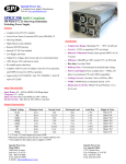
OWNER’S AND SERVICE MANUAL
Version 2
ROXOR GAMES, INC.
7793 Burnet Rd., Suite 143
Austin, Texas 78731
1-877-904-9634
Table of Contents
TABLE OF CONTENTS....................................................................................................... 2
INTRODUCTION.................................................................................................................. 3
DESCRIPTION ...................................................................................................................... 3
GAME PLAY ........................................................................................................................ 3
INSTALLATION AND SET-UP ............................................................................................ 7
SAFETY PRECAUTIONS ......................................................................................................... 7
PARTS LIST......................................................................................................................... 7
YOU WILL NEED:................................................................................................................. 7
HARDWARE INSTALLATION .................................................................................................... 8
STICKER AND MARQUEE INSTALLATION................................................................................ 11
MAINTENANCE AND TROUBLESHOOTING................................................................... 14
MAINTENANCE................................................................................................................... 14
TROUBLESHOOTING ........................................................................................................... 15
WARRANTY ...................................................................................................................... 23
2
Introduction
Description
Thank you for purchasing Roxor Games' In the Groove®, the most advanced dance rhythm
game to date.
In the Groove® is a fun and challenging game of perceptive and physical skill, which is
simple to learn, exciting to play, and offers players a wide range of levels to play at to
achieve the perfect individualized gaming experience. Players watch the arrows on the
screen to know which floor sensor(s) to step on, and listen to the beat of the music to know
when. The game is lost if a player misses too many steps. It is addictive, immersive, and a
great way to get the whole body into the gaming experience.
The skills involved are physical coordination, timing, stamina, and visual perception.
Different selectable skill levels let players choose songs that can range from one step every
couple of seconds to over 18 steps per second. Players typically choose songs that offer a
challenge, but are still passable. In this way, game play is always fun and fresh as the skill
of the player naturally increases. The goal for many players is to be able to pass the
hardest songs, as it shows considerable physical abilities and is impressive to watch. For
others, it simply offers an immersive and fun way to dance to music, especially for those
who want to dance but don’t know how.
The hardware and graphics have been designed using only the finest materials, and the
electronics in the game have been extensively tested to assure years of trouble-free
service. Programming options are, likewise, easy to understand and adjust.
Game set-up is a snap. Just plug in to an existing cabinet, set a few programmable options,
and you’re ready to go!
Game Play
Overview
The game begins when the player has inserted enough coins to create 1 "credit". The
player then presses the green Start button to start the game.
The player then moves through a number of selection screens in which s/he choose the
game mode, the number of players, song and difficulty, and optional modifiers to game
play. Once game play starts, the object of the game is to step on the floor panels in synch
with the on-screen arrows arriving at their targets. The steps correspond to the timing of the
music, and the player must use the music to get their timing perfect. The timing is scored
on a 6-scale range from Miss to Fantastic, and points are added to or subtracted from the
player’s accuracy score accordingly. The score is percentage-based, and at the end of a
song a classification is given on an 18-scale range from F (fail) to 4 Gold Stars.
3
If a single player is playing and misses many steps, their life meter will empty and they will
"Fail" the song. When a player fails, the Game Over screen will appear after the end of the
current song. If two players are playing and one fails but the other passes, they both can
continue playing. If both players fail, the result is the same as for a single player that fails.
Game Modes
Dance
Dance Mode is the most basic and most common mode in the game. After
choosing Dance, the player chooses the Player Configuration (One Player,
Two Player, or Doubles), then chooses a song. The player can quickly push
the Start button immediately after choosing a song to enter the Modifiers
screen and adjust things such as the arrow movement speed, visibility of
arrows, direction of arrow travel, etc. in order to add or remove challenges to
suit his/her taste. The round then starts and the song begins to play and
arrows travel up the screen. The player must step on the right pad at the right
time, otherwise his/her life meter (on the sides of the screen) will drop.
Improvements will make the meter recover and rise. If the meter gets too low,
the life meter and background will flash red. If it drops all the way down the
round is lost; once the round is lost, the player’s side of the background goes
dark, and the score stops counting. The player can finish the song, but will
then see the "Failed" and "Game Over" screens. The Life Difficulty as well as
the maximum number of songs per game can be set in Service Options
Menu.
Battle
On selection, the player chooses one or two players and then the selects a
song. The player can then enter the Modifier Menu as in Dance Mode, though
the options are more limited comparatively. This game mode is similar to
Dance Mode except that the life meter and score are replaced by a "tug of
war" meter. If one player is stepping more accurately, their side of the bar will
grow; the winner is determined by who has the larger section of bar at the end
of the song. In addition to this, stepping accurately will cause arrow modifier
attacks (such as causing the arrows to rotate in place or blink) to be launched
at the opponent, disrupting their ability to step accurately. In Battle, the player
does not fail and is automatically given the number of rounds specified in
Service Options Menu.
Marathon
On selection, the player chooses the dance style then a course. The player
can also enter the Modifier Menu just as they would in normal Dance Mode. A
course is a set of four or five songs which play one right after the other, with
no pause in between. The actions are similar to Dance Mode, except that at
certain points arrow modifiers have been hand crafted to cause arrows to
behave in unique ways. The player must continue to step accurately following
the same rules as in Dance mode. If the meter falls completely, the player’s
game will immediately end (however the player is allowed to finished their first
song if they fail that early in a course).
4
Survival
On selection, the player chooses the style then a course. The player is not
allowed to enter the Modifier Menu as in other game modes. This is part of
the challenge in Survival mode. Survival mode uses a special set of courses
and replaces the regular life meter with a ticking clock. The clock slowly runs
down over time, and the player fails when the clock reaches 0. Players can
slow down the clock's drain by stepping accurately, or speed up the drain if
they miss steps. A large clock bonus is also awarded between each round.
Dance Styles
Use the green Left and Right arrows to choose the setup, then press the Start button.
1-Player
One player inserts one credit and chooses one side of the stage, giving them
4 panels to play on. The other side is not played on unless a second player
joins in.
2-Player
Each player inserts one credit and chooses one side of the stage, giving them
each 4 panels to play on.
Double
One player inserts two credits and uses the entire stage, giving them 8 panels
to play on. Doubles is not selectable in Battle Mode.
Difficulty and Song Selection
Use the green buttons and floor panels to adjust the song and settings, then press the Start
button. Press the Start button one more time within 3 seconds to enter the Modifier Menu
(for advanced players).
Song
Use the green Left and Right buttons to turn the song wheel clockwise or
counter-clockwise. Statistics for the highlighted song and difficulty level will be
displayed.
Difficulty
To change the difficulty, tap the Up floor panel twice quickly to make it easier,
and tap the Down floor panel to make it harder. Or simply select the desired
difficulty in the Modifier Menu. (To enter the Modifier Menu, simply hit the start
button twice instead of once when selecting a song to play.)
5
USB Memory Cards
After inserting a credit and before choosing a dance style, a player may insert a memory
card into the box on the left side of the monitor. Memory cards have the following uses:
For the Player:
Name
The card supplies the machine with a player’s chosen set of initials, which is
displayed in place of “Player 1” or “Player 2” designations, and is supplied to
the machine for use in the High Scores list.
Edits
The player can create their own steps patterns to the existing songs and store
them on the USB card. When the card is being used, these additional step
patterns are selectable on the Select Song screen. Edits show up and are
chosen in the same way that difficulties are chosen.
Stats
When a memory card is present, the machine and player statistics are
recorded to the memory card. This includes high scores, screenshots,
modifiers and name preferences.
For the Service Technician:
Machine
Info
From the Service Options Menu, one can download or upload machine stats
such as bookkeeping information and high scores using a USB memory card.
Updates
(ITG2 and newer only) The game software can be upgraded by a Machine
Update file on a USB memory card. See the Maintenance section of the
manual for instructions.
6
Installation and Set-Up
Safety Precautions
Important! Failure to follow these directions closely could cause serious damage to
you and/or your game.
Warning: Before installing your new In The Groove® Upgrade kit, please be sure that your
monitor chassis has an isolation transformer. Refer to Part 1 of the Hardware Installation
section. In most cases the Japanese dance cabinets have a Toshiba chassis that has an
isolation transformer built into it. The Korean cabinets, however, usually use a Hong EUN
chassis without isolation. If you have a system with the Hong EUN chassis or any other
make chassis without isolation, you must first install an isolation transformer. Failure to
do so will result in damage to the chassis, power supply and the In The Groove® board. For
questions or support please contact your Authorized Roxor Distributor.
Warning: When installing this game, a 3-prong grounded receptacle must be used. Failure
to do so could result in serious injury to yourself or others. Failure to use a grounded
receptacle could also cause improper game operation and/or damage to the electronics.
Do not defeat or remove the grounding prong on the power cord for the same reasons as
given above. Using an improperly grounded game could void your warranty.
In some cases, an outlet may have a grounding socket, but may not actually be grounded.
Ensure that the outlet is grounded by using an electrical tester. These can be obtained
inexpensively at hardware stores.
Warning: Under no circumstances should power be
plugged into the connector on the IO Board. This will
result in irreparable damage to the IO Board and is not
covered under warranty. Refer to Figure 1.
Figure 1: IO Board
Parts List
You Will Need:
BoXoR with power cable
USB box with 4 mounting screws
Spade drill bit
Sticker kit
Squeegee
Marquee insert
User’s Manual
Phillips head screwdriver (BoXoR)
Electric drill (USB box)
Glass cleaner (Stickers)
Electrical Tester (BoXoR)
7
Hardware Installation
Part 1: Verify that an Isolation Transformer is Present in the Monitor Chassis
1. Determine the voltage standard in
your area. If it is 115v-120v
(generally the US), proceed to the
next step. If it is 220v-240v
(generally Europe and Asia),
proceed to Part 2 and skip this
section.
2. Remove the 4 screws holding the
metal panel in place. Remove the
panel and set it aside.
3. Locate the isolation transformer. It
is usually to the left of the tube and
across from high voltage. Refer to
Figure 2. If the isolation transformer
is present, proceed to Part 2.
4. If there is no isolation transformer,
one must be installed before
proceeding.
Figure 2: Monitor Chassis
Part 2: Remove the Existing Hardware from the Cabinet
1. Ensure that the power outlet to be used is grounded.
2. Turn off the power and unplug the cabinet.
3. Open the back panel of the cabinet by removing the two Phillip’s retaining screws
and settting the panel aside.
4. Identify the original game processor positioned either horizontally or vertically.
5. Carefully disconnect all cables running to the existing metal box. There will be four
light control molex connectors: a red connector, an orange connector labeled P1, a
white connector labeled P2, and a smaller white molex with two wires. Remove the
JAMMA connector and the stereo RCA cables. Put them aside.
6. Remove the two retaining wing nuts located on the wood bounding board holding the
game processor.
7. Slide the wooden mounting board with game processor straight out and lay the
board down on a working surface.
Part 3: Remove the Hardware Box from the Wooden Mounting Board
1. Identify the four hold down screws securing the original game processor in place.
2. Using a Phillip’s head screwdriver, remove the four screws.
3. Lift off the metal box, and set aside.
8
Part 4: Mount the BoXoR on the Wooden Mounting Board and Insert in Cabinet
1. Place the BoXoR on the board so that it sits between the
edge of the board and the handle. Be sure to allow at
least 2” from the back edge to allow room for cables.
See Figure 3.
2. Using the original hold down screws, secure the four
screws into the wood. You will be making new holes
in the board.
3. Fitting it into the same place it came from, slide the
mounting board into the cabinet until it is flush with the
shelf it sits on. Note that the electrical connections on
the BoXoR should be facing out toward you.
Figure 3: Placement
Part 4: Reconnect all Cables in the Cabinet
1. Plug the stereo audio RCA cables into the audio sockets on the back of the BoXoR.
2. Plug the large JAMMA connector into the edge board above the audio sockets. Note
that some JAMMA connectors have plastic tabs that need to be trimmed to fit. It is
ESSENTIAL that the connector snaps into place or have a solid fit. If it slips off while
either the cabinet or BoXoR is powered on, damage to electronics will result. Please
contact your ITG distributor if your JAMMA connector has a loose fit.
Figure 4: Wiring Diagram
Figure 5: Plug Detail
9
3. Insert the molex connectors in the next few steps. Note that the direction of the tab
on the plug is crucial and improper attachment can result in damage to the IO board.
Refer to Figure 4.
4. Plug the red cabinet lights connector into the socket labeled “Cabinet Lights“.
5. Plug the orange “P2 lights” connector into the socket labeled “P2 Lights”.
6. Plug the white “P1 lights” connector into the socket labeled “P1 Lights”.
7. Plug the remaining small white “Neon Lights” connector into the smallest socket.
Notice that this plug goes in “flipped” compared to the other molex connectors.
See Figure 5.
8. Switch the BoXoR power supply to the local voltage standard if necessary, using a
small flat head screwdriver.
Part 5: Install the USB Hub and Enclosure
1. With a pencil, mark a point 8-1/2” back from the
front plate and 3” up from the base of the cabinet
on which the monitor piece rests. See Figure 6.
2. Attach the spade bit to the power drill. Place the
point of the bit on the pencil mark and begin to drill.
Use steady pressure to bore through the wood.
3. Run the USB cable into the new hole in the
cabinet. See Figure 7.
4. Using the 4 Phillip’s head screws, attach the case
to the cabinet. Tapping the screws with a hammer
to help get them started will ensure they go in
easily. See Figure 8.
5. Inside the cabinet, plug the blue USB hub cable into
the USB cable attached to the BoXoR.
Figure 7: Insert Cable
Figure 6: Drill Hole
Figure 8: Attach
10
Part 6: Power on the system
1. Remove the 4 screws retaining the access plate
located in the lower right corner of the dance cabinet.
2. Pass the power cable and optional network cable into
the cabinet through the access hole. Pass them under
the interior support wall and connect to the back of
the ITG game controller as shown in Figure 9.
3. Set the voltage switch of the BoXoR’s power supply to
your area voltage standard.
4. Replace the cabinet back cover and screw into place.
5. Reconnect the external power cable to the dance
Figure 9:
cabinet. Note: a power surge strip is recommended to
Power Cable Passage
protect your investment in the ITG game system. This
also doubles as a main system power switch as the
cabinet switch will not turn off the ITG game controller.
6. Turn the dance cabinet on.
7. Turn the ITG power supply on.
8. Once you see the "In The Groove" splash screen on the cabinet monitor, press the
top operator button located behind the coin door. Run the "Input Test" and "Light
Test" to insure everything is connected correctly.
Sticker and Marquee Installation
How to Apply the ITG Stickers
The ITG stickers are printed on a low-tac pressure sensitive vinyl, which allows for
repositioning until pressure is applied to the vinyl. Once pressure is applied, the adhesive is
activated and the sticker is permanent. Stickers can be affixed using one of the following
methods. Both are equally effective when instructions are followed carefully. Method 1 is
much easier for larger stickers.
Method 1: For each sticker, remove the backing and lightly spray the adhesive side of the
sticker with a mild glass cleaner such as Windex. This will make it possible to apply the
sticker and slide it into the right position. Once positioned, gently run a squeegee or plastic
card over the sticker to push out as much of the glass cleaner as possible. When the
sticker can no longer slide around and most of the liquid has been squeezed out, squeegee
the sticker while applying pressure, to activate the adhesive. Any liquid not released should
dry in 12 to 24 hours.
Method 2: Peel each sticker off the backing and stick to the surface. (For large pieces, peel
back only small portions of the backing and lightly stick down to position. Then remove the
rest of the backing while lightly smoothing the rest of the sticker down.) As long as pressure
has not been applied, it is possible to peel up the entire sticker and position again. Once
the positioning is right, run a card or squeegee over the sticker, applying pressure to
activate the adhesive.
11
Part 1: Attach Monitor Sticker
1. Using scissors or a blade, cut the monitor sticker away from the sticker sheet. Do not
peel away any backing yet. Simply cut the piece out.
2. With the game running, place the sticker against the screen. Position the sticker so
that the screen image is completely visible and not blocked. Place marks on the
glass or use tape to indicate the positioning of the sticker. Then turn off the game
and cabinet.
3. Unscrew the metal plates at the top and bottom of the monitor. These hold the
monitor glass in place. Remove the plates to expose all edges of the glass.
4. Apply the monitor sticker to the glass according to the marks made in Step 2.
Use one of the two methods described in the previous section titled How to Apply
the ITG Stickers.
5. If necessary, use a sharp blade to trim any excess sticker on the outer screen edges
once the sticker is applied.
6. If any of the printed images on the inside of the glass shows through, turn off the
cabinet and take out the entire glass plate. Use a scraper or solvent to remove
the paint.
7. Replace the metal plates.
Part 2: Remove Existing Stickers and Apply Remaining ITG Stickers
1. Peel, scrape or use a solvent to remove all existing stickers or paint, and wipe down
the metal cabinet surfaces with a glass cleaner.
2. Use Figure 10 to determine the placement of each sticker. Apply using one of the
two methods described in the section titled How to Apply the ITG Stickers on the
previous page.
Part 3. Replace the Marquee
1. If there is a plastic cover over the cabinet marquee, remove it by removing the
screws on the sides and top.
2. If the cover has printing on the back, use a solvent to remove it so that the cover is
clear.
3. Slide the ITG marquee into the slots on the top and bottom of the marquee holder
and replace the plastic cover.
4. Replace the screws. If screws do not have sharp points, it may be necessary to poke
holes in the marquee with a blade or point first.
12
Sticker and Marquee Placement
A
B
C
D
E
F
G
H
I
Marquee. See Page 10, Part 3 for instructions.
Monitor sticker. See Page 10, Part 1 for instructions.
Middle plate sticker. Apply above the Front Plate sticker if there is no separate plate.
Standard Front Plate sticker. Use if your cabinet has NO memory card panel,
and discard stickers E and F.
Memory Card Front Plate sticker. Use if your cabinet has a memory card reader,
and discard sticker C.
Memory Card Plate sticker. Use if your cabinet has a memory card panel.
Side Stage Stickers. Apply to each side of the stage.
Corner Stage Stickers. Apply to the angled corners on each side of the stage.
Coverup Stickers (not shown): Use to cover unnecessary screw holes.
Figure 10: Sticker Placement
13
Maintenance and Troubleshooting
Maintenance
Machine Updates
The game software can be upgraded with a Machine Update file on a USB pen drive.
Machine Update files can be obtained from the In The Groove® web site.
1.
Purchase or borrow a USB pen drive. These drives can be obtained from Wal-Mart,
Target, K-Mart, Radio Shack, any electronics store, and most office supply stores.
Any drive size 64MB or larger will work.
2. Plug the pen drive into any computer connected to the internet.
3. On the computer, open a web browser and enter in the location:
http://www.inthegroove.com/updates.
4. Click on the latest patch file for your version of In The Groove®. Choose to save the
patch file to the drive letter of your USB pen drive.
5. You should now see a file on the pen drive with a name similar to “ITG 2 00002.itg”.
6. Remove the pen drive and carry it to your ITG machine.
7. Open the service door and press the service button to enter the Service Options
screen.
8. Use the Left and Right buttons to highlight Machine Update, then press the Start
button.
9. A message will ask you to insert a memory card containing an update file. Plug your
pen drive into either of the machine’s 2 memory card USB ports.
10. The Machine Update will be read from the pen drive and applied to the machine.
This may take a minute or two.
11. Press the Start button to reboot the machine to complete the Machine Update.
Factory Reset
To erase all scores, all installed Machine Updates, and all saved settings:
1.
2.
3.
4.
Open the cabinet’s service door.
Reboot the BoXoR by unplugging and re-plugging the BoXoR’s power cable
Hold the service button inside the service door while the game is booting.
Continue holding the service button until you hear a sound, then release the service
button.
The sound indicated that the factory reset was successful. The machine will then reboot
automatically.
14
Troubleshooting
For updated troubleshooting information, please visit http://www.roxorgames.com/support/
INPUT PROBLEMS
The up and right panels on both p1 and p2 sides are completely unresponsive
Possible cause:
1. There is a short on the orange molex connector that attaches to the I/O board, or
somewhere on the line that runs from the orange molex into the cabinet.
All floor panels are completely unresponsive
Possible causes:
1. The I/O board is not being initialized because the cabinet and BoXoR haven't been
activated at the same time.
2. The I/O is not plugged in to the JAMMA.
3. The I/O board is not connected to the computer inside the BoXoR case via USB.
4. The I/O board has been damaged or destroyed, likely due to the cabinet being
plugged into an ungrounded outlet or the cabinet not having an isolation transformer
installed.
The floor panels become less responsive over time, and after rebooting cabinet and
BoXoR the pads are again responsive
Possible causes:
1. The floorboard controllers are faulty, or they receive weak signals from any of the
four sensors under each of the eight pads. Sensors should be tested individually.
2. The USB cable that runs from the CPU to the USB hub on the outside of the cabinet
is too close to the neon transformer (the device that powers the neon lights on the
front of the cabinet - usually a long white rectangular box).
3. The cabinet is not grounded: it is not plugged into a grounded outlet, the ground pin
on the power cord has been chopped off, or it has an internal grounding issue.
4. Molex connectors that connect to the I/O are loose or have a short in the lines
running to them.
5. The neon transformer has been opened, releasing interference. Ensure that the
plastic case is entirely closed or shield it in another manner.
The input signal is weak, and stomping is necessary for the sensors to register
1. The floorboard controllers are faulty, or they receive weak signals from any of the
four sensors under each of the eight pads. Sensors should be tested individually.
15
The machine operates correctly for a while, then suddenly all of the cabinet lights
turn on, the game continues running normally on the screen but does not respond to
input
Reason: Communication between the computer and the ITG-IO board was lost.
Rebooting the BoXoR may temporarily fix this problem. Contact Roxor for further
instructions.
In The Groove 2 only: A black band will appear on the screen and say "I/O error"
Possible causes are:
1. The I/O board has been damaged or destroyed, likely due to the cabinet being
plugged into an ungrounded outlet or the cabinet not having an isolation transformer
installed.
The game boots correctly, but after booting all cabinet lights are stuck on and the
game does not respond to input.
Reason: The game was unable to initialize the ITG-IO board.
In The Groove 2 only: A black band will appear on the screen and say "I/O error"
Possible causes are:
1. The cabinet was not powered on at the time the BoXoR booted up. Turn off the
power to both the cabinet and the BoXoR, then power up the cabinet power, then
power up the BoXoR.
2. The I/O board is not being initialized because the cabinet and BoXoR haven't been
activated at the same time.
3. The I/O is not plugged in to the JAMMA.
4. The I/O board is not connected to the computer inside the BoXoR case via USB.
5. The I/O board has been damaged or destroyed, likely due to the cabinet being
plugged into an ungrounded outlet or the cabinet not having an isolation transformer
installed.
LOCKUP PROBLEMS
Pads lock up during gameplay, or "I/O Error" is displayed on screen
Possible causes are:
1. The USB cable that runs from the CPU to the USB hub on the outside of the cabinet
is too close to the neon transformer (the device that powers the neon lights on the
front of the cabinet - usually a long white rectangular box).
2. The cabinet is not grounded: it is not plugged in to a grounded outlet, the ground pin
on the power cord has been chopped off, or it has an internal grounding issue.
16
Game freezes during gameplay or attract
Possible causes are:
1. The USB cable that runs from the CPU to the USB hub on the outside of the cabinet
is too close to the neon transformer (the device that powers the neon lights on the
front of the cabinet - usually a long white rectangular box).
Game sometimes makes a stuttering sound and reboots
Reason: RAM errors are causing the game to reboot.
Possible causes are:
1. The RAM sticks are not fully secured to the motherboard. Open the BoXoR and
remove both sticks of RAM. Make sure that the RAM slots are free of dust, then
reinsert the RAM sticks one at a time. Ensure that the plastic end clips have
completely secured the RAM sticks to the motherboard.
2. One or both of the RAM sticks are defective. Contact Roxor for help troubleshooting
this.
SOUND PROBLEMS
The game displays correctly, but there is no sound
Possible causes are:
1. The two sound wires coming from the amplifier box are not plugged into the RCA
jacks on the ITG-IO board.
2. The sound amplifier unit is damaged.
3. The 1/8" cable is not securely plugged in to either the IO Board or the motherboard,
or both.
LIGHT PROBLEMS
Floor lights don't work but input does
Possible cause:
1. The floorboard controllers have been damaged or tampered with.
The neon (subwoofer) lights "tick" or flicker
Possible cause:
1. The neon transformer is failing. Unplugging power to the neon lights may temporarily
solve this problem until the transformer can be replaced.
17
Game sometimes enters the Service Menu randomly during play, inserts credits
randomly during play, and shows static on the screen
Possible cause:
1. The lights driver board is failing. The MOSFETS on the lights driver board need to
be replaced. Please contact Roxor for help troubleshooting this.
STARTUP / POWER PROBLEMS
After turning on the power, all of the cabinet lights turn on and there is no image on
the screen
Possible causes:
1. The I/O board is not being initialized because the cabinet and BoXoR haven't been
activated at the same time.
2. The I/O is not plugged in to the JAMMA.
3. The I/O board is not connected to the computer inside the BoXoR case via USB.
4. The I/O board has been damaged or destroyed, likely due to the cabinet being
plugged into an ungrounded outlet or the cabinet not having an isolation transformer
installed.
In The Groove 1 only: The game never starts and shows scrolling text as it reboots
continuously
Reason: The hard drive's serial number does not match the BoXoR's serial number. ITG
hard drives are tied to a particular BoXoR and cannot be used in different BoXoRs. (Applies
to ITG1 only)
Possible cause:
1. There was a handling mistake and the wrong hard drive was shipped to you. Please
contact your distributor for help troubleshooting this.
After powering on the BoXoR, the BoXoR makes a single long beep sound
Reason: The CMOS data on the BoXoR motherboard has become corrupt.
Possible causes are:
1. A power spike caused corruption. Please contact Roxor for help troubleshooting this.
18
After powering on the cabinet and the BoXoR, nothing appears on screen and the
BoXoR does not beep
Possible causes are:
1. The power supply has failed. Roxor is proud to use Sparklepower power supplies.
They have large componentry and are extremely reliable. This means an error of this
sort may indicate a problem with the wiring in your building, or perhaps the ground
pin on the power cord running to the BoXoR has been damaged or tampered with.
2. The motherboard or CPU has been damaged. Please contact Roxor for help
troubleshooting this.
After powering on the cabinet and BoXoR, there is a plain black screen that says
"DISK BOOT FAILURE"
Possible causes are:
1. The hard drive may have been damaged or destroyed.
2. The hard drive is no longer plugged in to the Motherboard, or the IDE cable
responsible for this connection is bad.
3. There is a problem with the motherboard: it may have been tampered with.
After powering on the cabinet and BoXoR, there is a plain black screen that says
"dongle initialization failed."
Reason: The security dongle connected to the BoXoR motherboard could not be initialized.
1. Open the BoXoR and verify that the security dongle is fastened securely.
2. The security dongle may be damaged. Please contact Roxor for help troubleshooting
this.
USB MEMORY CARD PROBLEMS
The USB memory card is not detected when plugged into the USB memory card hub
1. ITG1 only: Only very specific models of memory cards are supported. If an
unsupported model of memory card is plugged in, the game will simply ignore it as if
no card was plugged in. ITG2 supports a much larger set of USB memory card
models.
2. Trace the wiring from the USB memory card hub back to the BoXoR.
• Verify that the USB cable connected to the hub has not been pulled loose.
• Verify that the USB cable connected running from the hub is connected to the
USB cable running from the back of the BoXoR.
• Open the BoXoR and verify that the USB cable that runs out the back of the
BoXoR is still plugged in. Use the USB port diagram from the section "SelfCheck Errors on Startup" to verify that both USB devices are plugged into the
correct USB ports on the motherboard.
19
The game reboots when a USB device is plugged in, or displays "Card
Disconnected" during gameplay, then immediately locks up.
Possible cause:
1. ITG1 only: This is usually a symptom of USB devices plugged into the BoXoR
motherboard incorrectly. Use the USB port diagram from the section "Self-Check
Errors on Startup" to verify that both USB devices are plugged into the correct USB
ports on the motherboard.
MONITOR PROBLEMS
The game image is too narrow and doesn't fill the width of the monitor
Reason: The video mode used by the In The Groove® software does not use the entire
width of the monitor.
Many monitors offer adjustment controls that can make the image fill most of the
screen. Some monitors though cannot be adjusted far enough to make the image wide
enough.
There is no way to correct this problem in the In The Groove 1 software. We are
investigating solutions for In The Groove 2 and expect to release a Machine Update
patch that fixes this. Contact Roxor for current information on this issue.
COIN PROBLEMS
The mechanical coin meter doesn't work
Reason: ITG-IO board does not pulse the JAMMA coin count wire. This is a hardware
limitation of the board.
1. Solution: The coin count must be checked by using the Service Menu:
1. Open the service door.
2. Press the Service button.
3. From the Service Menu, choose Bookkeeping.
4. Read the "All-time coin count".
2. Alternative Solution: Contact Roxor for general instructions on rewiring your
mechanical coin meter to work with ITG
20
SELF-CHECK ERRORS ON STARTUP (In The Groove 2 and newer only)
On startup, In The Groove® performs several tests to ensure all hardware is present and
correctly connected. Possible errors are listed below.
"The input/lights controller is not connected or is not receiving power. Please
consult the service manual."
•
•
•
The ITG-IO input/lights board is located on the rear face of the BoXoR unit and is
powered by 5V from the JAMMA connector.
Check that the JAMMA connector is fully connected to the ITG-IO board.
Open the BoXoR and verify that the USB data cable running from the ITG-IO board
to the motherboard USB port is connected at both ends.
"The memory card USB hub is not connected. Please consult the service manual for
details."
•
•
•
The memory card USB hub is the external box that allows players to plug in USB
pen drives.
Memory cards are an important feature of the game, and operators are highly
encouraged to plug in the memory card box that came with the ITG BoXoR upgrade
kit.
Verify that the cable running from the memory card box and through the inside of the
cabinet is plugged in to the USB extension cord running from inside the BoXoR.
"The input/lights controller and the memory card USB hub are on the same USB bus.
Both devices are on bus 1 (or 2). These two devices must be plugged into separate
USB busses. Please consult the service manual."
•
•
The ITG-IO board and memory
card USB hub are both USB
devices. For optimal
performance, these devices
must be plugged into certain
USB ports on the motherboard.
See Figure 11 for the correct
configuration of the USB
devices. Use the location of the
ports in the pictures to
determine whether your
motherboard is a "Type 1" or
"Type 2".
Figure 11: USB Slots on Motherboards
21
"Serial mismatch."
Reason: The hard drive's serial number does not match the BoXoR's serial number. ITG
hard drives are tied to a particular BoXoR and cannot be used in different BoXoRs.
Possible causes are:
1. There was a handling mistake and the wrong hard drive was shipped to you. Please
contact your distributor for help troubleshooting this.
22
Warranty
Roxor Games warrants all components in the In the Groove® upgrade kit to be free of
defects in materials and workmanship for a period of ninety (90) days from the date of
purchase.
This warranty does not cover items damaged due to normal wear and tear, subjected to
abuse, improperly assembled by the end user, modified, repaired, or operated in a fashion
other than that described in the service manual.
If your In the Groove® game fails to conform to the above-mentioned warranty, Roxor’s
sole responsibility shall be at its option to repair or replace any defective component with a
new or remanufactured component of equal to or greater O.E.M. specification.
Roxor will assume no liability whatsoever, for costs associated with labor to replace
defective parts, or travel time associated therein.
Roxor’s obligation will be to ship free of charge, replacement parts by UPS Ground, US
Mail, or other comparable shipping means. Any express mail or overnight shipping expense
is at the cost of the purchaser.
Products will be covered under warranty only when:
a. The serial number of the game with the defective part is given
b. The serial number of the defective part, if applicable, is given
c. Defective parts are returned to Roxor, shipping pre-paid, in a timely fashion, if
requested by Roxor
d. A copy of the sales receipt is available as proof of purchase upon request of
Roxor
Roxor Games’ distributors are independent, privately owned and operated. In their
judgment, they may sell parts and accessories other than those manufactured by Roxor.
We cannot be responsible for the quality, suitability, or safety of any non-Roxor part, or any
modification, including labor, which is performed by such a distributor.
23