1
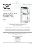
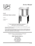
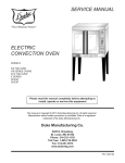
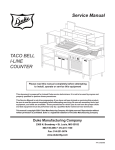
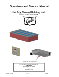
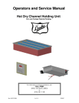
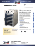
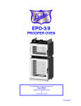
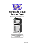
Service Manual
BAKING CENTER
AHPO / EPO
PROOFER OVEN
MODELS
AHPO-6/18
EPO-3/9
Please read this manual completely before attempting to install,
operate or service this equipment
This document is prepared for trained Duke service technicians. It is not to be used by anyone not properly qualified
to perform these procedures.
This Service Manual is not all encompassing. If you have not been trained on servicing this product, be sure to
read the manual completely before attempting servicing. Be sure all necessary tools, test equipment, and skills are
available. Those procedures for which you do not have the proper skills and test equipment must be performed only
by a qualified Duke trained service technician.
This manual is Copyright © 2009 Duke Manufacturing Co. All rights reserved.
Reproduction without written permission is prohibited. Duke is a registered
trademark of the Duke Manufacturing Co.
Duke Manufacturing Co.
2305 N. Broadway
St. Louis, MO 63102
Phone: 314-231-1130
Toll Free: 1-800-735-3853
Fax: 314-231-5074
www.dukemfg.com
P/N 512981B
Service Manual for AHPO / EPO Proofer Oven
IMPORTANT WARNING AND SAFETY INFORMATION
IMPORTANT FOR YOUR SAFETY
READ THIS MANUAL THOROUGHLY BEFORE OPERATING, INSTALLING OR PERFORMING
MAINTENANCE ON THE EQUIPMENT.
Failure to follow instructions in this manual can cause property
damage, injury or death.
Do not store or use gasoline or other flammable vapors or liquids
in the vicinity of this or any other appliance.
This unit is designed for a fixed, permanent (hard) wired connection
to an appropriate AC power source as stated on the model label. The external
wiring interface must be installed as per the local AC wiring codes.
Always lockout / tagout the unit from the main AC power source
before removing any sheet metal panels or attempting to service this unit. Failure
to comply to this procedure may cause property damage, injury or death.
Improper installation, adjustment, alteration, service or maintenance
can cause property damage, injury or death. Read the installation, operating and
maintenance instructions thoroughly before installing or servicing this equipment.
Do not operate this equipment without properly placing and
securing all cover and access panels.
device.
2
In the event of a power failure, do not attempt to operate this
Service Manual for AHPO / EPO Proofer Oven
TABLE OF CONTENTS
INTRODUCTION............................................................................................................................................ 4
INSTALLATION...................................................................................................................................... 4
OPERATION............................................................................................................................................ 4
CLEANING............................................................................................................................................. 4
TOOLS ......................................................................................................................................................... 4
STANDARD............................................................................................................................................ 4
SPECIFICATIONS........................................................................................................................................... 5
REMOVAL AND REPLACEMENT OF COMPONENTS.............................................................................. 6
ELECTRICAL LOCKOUT/TAGOUT PROCEDURE............................................................................ 6
COVERS AND PANELS......................................................................................................................... 6
General Service Notes..................................................................................................................... 6
Proofer Rear Panel........................................................................................................................... 6
Oven Rear Panels............................................................................................................................. 6
Oven Fan Cage and Wire Harness Cover........................................................................................ 7
Proofer Floor Panel.......................................................................................................................... 7
Oven Ceiling Panel.......................................................................................................................... 8
Control Panel................................................................................................................................... 8
AC Power Access Panel.................................................................................................................. 9
AC INPUT VOLTAGE WIRING CONNECTIONS............................................................................... 9
INTERNAL LAMP REPLACEMENT.................................................................................................... 9
CONTROL PANEL COOLING FAN.................................................................................................... 10
PROOFER LIGHTS CIRCUIT BREAKER.......................................................................................... 10
BUZZER................................................................................................................................................ 11
OVEN POWER SWITCH..................................................................................................................... 12
OVEN THERMOSTAT.......................................................................................................................... 12
OVEN TIMER....................................................................................................................................... 12
PROOFER POWER SWITCH............................................................................................................... 13
PROOFER THERMOSTAT................................................................................................................... 13
PROOFER HUMIDITY CONTROL..................................................................................................... 14
PROOFER TIMER................................................................................................................................ 14
PROOFER HEAT ELEMENTS............................................................................................................. 15
PROOFER HUMIDITY ELEMENT..................................................................................................... 15
PROOFER CIRCULATION FAN......................................................................................................... 16
OVEN HEAT ELEMENTS.................................................................................................................... 17
OVEN CIRCULATION FAN................................................................................................................ 17
OVEN HI-LIMIT THERMOSTAT........................................................................................................ 18
DOOR GASKET REPLACEMENT...................................................................................................... 18
OVEN SAFETY SWITCH.................................................................................................................... 18
ADJUSTMENTS............................................................................................................................................ 19
DOOR GASKET COMPRESSION CHECK........................................................................................ 19
DOOR GASKET ADJUSTMENTS....................................................................................................... 19
AIR WASH DOOR ADJUSTMENT..................................................................................................... 20
Air Wash Door Adjustment – Hinge Side...................................................................................... 20
Air Wash Door Adjustment – Handle Side............................................................................................ 20
MAINTENANCE........................................................................................................................................... 21
STAINLESS STEEL CARE................................................................................................................... 21
GENERAL CLEANING........................................................................................................................ 21
TROUBLESHOOTING.................................................................................................................................. 22
ELECTRICAL SCHEMATIC......................................................................................................................... 23
3
Service Manual for AHPO / EPO Proofer Oven
TOOLS
INTRODUCTION
INSTALLATION
STANDARD
For detailed installation instructions, refer to the Owner’s
Manual (502821A).
•
Standard set of hand tools.
•
VOM with AC current tester. (Any quality VOM or
DVM with a sensitivity of at least 20,000 Ohms per
Volt can be used.)
•
A ladder or other appropriate item to stand on, if servicing
the top of the unit.
OPERATION
For specific operating instructions, refer to the Owner’s
Manual (502821A).
CLEANING
For specific instructions, refer to the Owner’s Manual
(502821A).
4
Service Manual for AHPO / EPO Proofer Oven
SPECIFICATIONS
U.S. Patent. Other US and Foreign Patents Pending
Model AHPO or EPO
Shipping Weight:
Carton Box
625 lbs / 284 kg
Shipping Weight:
Wooden Crate
760 lbs / 345 kg
Volts
AHPO /
EPO
Phase
Hz
Watts
Amps
208
1
60
6650
32.0
208
1
50
6650
32.0
230 (220-240)
1
60
6650
32.0
230 (220-240)
1
50
6650
32.0
230 (220-240)
3
60
6650
16.7
230 (220-240)
3
50
6650
16.7
400 (380-415)
3N
60
6650
16.7
400 (380-415)
3N
50
6650
16.7
5
Service Manual for AHPO / EPO Proofer Oven
REMOVAL AND REPLACEMENT OF COMPONENTS
ELECTRICAL LOCKOUT/TAGOUT
PROCEDURE
Before performing any service that
involves electrical connection or disconnection and/or
exposure to electrical components, always follow the
Electrical LOCKOUT/TAGOUT Procedure. Disconnect
all circuits. Failure to comply can cause property
damage, injury or death.
The Electrical LOCKOUT/TAGOUT Procedure is used to
protect personnel working on an electrical appliance. Before
performing any maintenance or service that requires exposure
to electrical components, follow these steps:
Most service can be accomplished without moving the
unit from its mounted position. However, if the unit is
moved during service, then these securing devices must
be reinstalled for continued protection against tip-over
and to meet other compliance regulations.
Proofer Rear Panel
Disconnect the electrical power to
the unit and follow lockout / tagout procedures.
Removing the Proofer Rear Panel, gains access to the Proofer
Light Fixtures, Proofer Burners connections, and Proofer
Wiring Harnesses.
1. In electrical box, place appliance circuit breaker into
OFF position.
1. Remove all of the self-tapping sheet metal screws that
secure the Rear Panel to the Proofer. Set aside for reuse.
2. Place a lock or other device on electrical box cover to
prevent someone from placing circuit breaker ON.
2. Remove the Rear Panel to gain access to the components
located at the rear of the Proofer.
3. Place a tag on electrical box cover to indicate that
appliance has been disconnected for service and
power should not be restored until tag is removed by
maintenance personnel.
4. Disconnect appliance power cord from electrical outlet.
5. Place a tag on the cord to indicate that unit has been
disconnected for service and power should not be restored
until tag is removed by maintenance personnel.
COVERS AND PANELS
Disconnect the electrical power to
the unit and follow lockout / tagout procedures.
Interior components and surfaces may be hot
if the unit has been in recent use.
General Service Notes
•
•
6
This unit uses water trays for humidity control. Remove
any water that might be present in the trays before
attempting service of any kind.
During its installation, this unit is required to be secured to
the building structure. There is also a Restraining Device
(a heavy, flexible metal cable) that was installed to prevent
the unit from moving beyond a certain distance in order
to prevent damage to the electrical conduit feeding it.
Figure 1. Proofer – Rear Panel Removed
Oven Rear Panels
Disconnect the electrical power to
the unit and follow lockout / tagout procedures.
The Oven section of the unit has three rear panels. The Center
Panel provides access to the Oven Light Fixtures and Oven
Light Fixture wiring harness. Right and Left Panels provide
access to the Oven Burner Element connections and Element
wiring harnesses.
1. Remove the screws securing the Center Panel. Retain
for reuse.
Service Manual for AHPO / EPO Proofer Oven
2. Remove the Center Panel to gain access to Light Fixtures
and wiring harness.
The Center Panel side screws must be removed
when removing either of the side panels.
Proofer Floor Panel
Disconnect the electrical power to
the unit and follow lockout / tagout procedures.
1. Remove screws securing the Proofer Floor Panel.
3. Remove the screws securing the Side Panels. Retain for
reuse.
2. Slide the panel out through the front of the unit being
careful not to damage the fan blades.
4. Carefully remove the insulation to gain access to the
Oven Burner Element connections and Oven Burner
Element wiring harness. Retain the insulation for reuse.
Access to the Proofer Heater Elements, Humidity Element,
Proofer Circulating Fan and Sensor is available with the
Proofer Floor Panel removed.
Figure 2. Oven – Right Side Panel Removed
Oven Fan Cage and Wire Harness Cover
Figure 4. Proofer Components with
Floor Panel Removed
Disconnect the electrical power to
the unit and follow lockout / tagout procedures.
Oven Ceiling Panel
1. Remove the four screws securing the Oven Fan Cage
to the top of the unit. Retain for reuse.
Disconnect the electrical power to
the unit and follow lockout / tagout procedures.
2. Remove the Cage to gain access to the Oven Fan Motor.
3. Remove the screws securing the Oven Fan Wire Harness
Cover to top of unit. Retain for reuse.
4. Remove the Oven Fan Wire Harness Cover to gain
access to the wiring harness and connections.
1. Remove the Humidity Pan.
2. Remove the screws securing the panel. Retain screws
for reuse.
3. It may be necessary to pry the panel forward from the
front of the unit. Be careful not to damage the fan blade
when removing the panel.
Access to Oven Heating Elements, Fan Blade and Sensors
is available with the Oven Ceiling Panel removed.
Figure 3. Oven Fan Cage and
Wire Harness Cover
7
Service Manual for AHPO / EPO Proofer Oven
Figure 5. Oven Components with Ceiling Panel
Removed
Control Panel
Figure 6. Components on Left Side of Control Panel
Disconnect the electrical power to
the unit and follow lockout / tagout procedures.
It is not necessary to move the unit to gain access to the
Control Panel. It might become necessary to remove the
unit from the wall if troubleshooting leads into other areas.
Refer to the specific component section of this manual when
replacing a component on the Control Panel.
1. Remove the four screws retaining the Control Panel to
the cabinet.
2. Carefully pull the front panel assembly away from the
cabinet while observing clearances of the wiring around
the controls.
All of the Operator Controls and related wiring are now
accessible.
DO NOT power on the unit while the Control
Panel is removed from the cabinet.
3. To troubleshoot for problems, use visual checks, an
Ohmmeter, the proper Schematic and Illustrations pages
for the version of the unit being serviced.
Figure 7. Components on Right Side of Control
Panel
When reassembling, make sure that wires do
not become pinched between the Control Panel and the
cabinet surfaces.
4. Replace all securing screws to the Control Panel before
re-powering the unit.
AC POWER ACCESS PANEL
Disconnect the electrical power to
the unit and follow lockout / tagout procedures.
8
Service Manual for AHPO / EPO Proofer Oven
Figure 8. AC Access and Connect Block with Panel
Removed
The AC Power Access Panel is located on the right side of
the unit next to the Control Cooling Fan.
Remove the two screws securing the panel to the unit to gain
access to the AC Connect Block.
AC INPUT VOLTAGE WIRING CONNECTIONS
Disconnect the electrical power to
the unit and follow lockout / tagout procedures.
Figure 10. Possible Wiring Block Configurations
If the service procedure requires the removal of any covers or
the Control Panel, then verify that there is no voltage present
within the unit before removing them.
Refer to the Electrical Schematic at the end of this manual
for additional information and a complete wiring diagram.
1. Remove the AC Connect Block Cover Plate. The AC
Connect Block Cover Plate is located to the right of the
Control Panel Cooling Fan on the right side of the unit.
2. Referring to Figure 9, use a voltmeter to check for the
presence of voltage.
If aluminum AC supply wire is
present, the unit is not properly wired and must
be taken out of service until it is properly rewired
using copper wire.
3. With AC power removed and proper Lockout and
Tagout procedures applied, ensure that the contacts on
the Connect Block are properly tightened.
INTERNAL LAMP REPLACEMENT
Figure 9. AC Wiring Block
Disconnect the electrical power to
the unit and follow lockout / tagout procedures.
Replacing an internal Lamp does not require removal of
any panels or covers.
9
Service Manual for AHPO / EPO Proofer Oven
Disconnect the electrical power to
the unit and follow lockout / tagout procedures.
Earlier
models
This fan is mounted to a ventilated metal panel to the right
of the Operator’s Control Panel and on the right hand side
of the unit.
When this panel is removed, you will also have access to
the Hi-Limit Thermostat, AC Power Contactor and, on the
later units, the Halogen Lamp Transformer and the Oven/
Proofer Buzzer.
Later
models
Figure 11. Lamps
Some earlier model units use a standard, clear glass, 120 V
lamp which are rated for oven use. Later model units use
12 V Halogen bulbs.
Avoid touching the glass envelope of a Halogen
bulb with your fingers as this will cause premature failure
of the bulb. If the bulb has been touched, clean it off with
an alcohol wipe. Always replace a bulb with one of proper
ratings for the unit.
1. Remove the screws securing the Louvered Vent on the
right side of the unit below the Oven Section. Retain
the screws for reuse.
1. Turn unit off and allow it to cool.
2. Tag and disconnect the cooling fan wires.
2. Unscrew and remove the Lens Cover and Lens Gasket.
3. Remove the four nuts securing the fan to the panel.
Retain the nuts for reuse.
3. Unscrew (old style) bulb or unplug (new Halogen style)
bulb.
4. Screw the new bulb in tight when replacing old style
bulbs. Halogen bulbs should be plugged in firmly. Avoid
touching the glass bulb with your fingers, use a cloth
or cloth gloves when installing a new bulb. If bulb is
touched use alcohol wipe to clean it.
Figure 12. Control Panel Cooling Fan
4. Remove the fan.
5. Reverse this procedure to install replacement fan.
6. Restore the unit to service and check for proper operation.
Also, verify proper fan rotation.
5. Briefly turn unit on and check for proper bulb lighting.
PROOFER LIGHTS CIRCUIT BREAKER
6. Turn unit off.
NOTE: Installing or replacing the Proofer Lights Circuit
Breaker only applies to models with halogen lights.
7. Place the Lens Gasket on the Lens Cover. Make sure it
is centered properly. If Lens Gasket is damaged replace
it.
8. Screw the Lens Cover over the Bulb tight making sure
the Lens Gasket seals against the Light Socket.
9. Return the unit to service; ensure it is operating correctly.
Disconnect the electrical power to
the unit and follow lockout / tagout procedures.
1. Place the Power Switches in the OFF position and follow
the Electrical Lockout and Tagout procedures.
2. Remove two screws securing the Access Panel.
CONTROL PANEL COOLING FAN
3. Disconnect the jumper wires to the Proofer Lights Circuit
Breaker.
4. Squeeze the tabs on the failed Proofer Lights Circuit
10
Service Manual for AHPO / EPO Proofer Oven
Breaker and push it out through the front of the Access
Panel.
Also, observe fan for proper rotation.
5. Reverse this procedure to install a new Proofer Lights
Circuit Breaker.
BUZZER
Use these procedures when installing a new Proofer Lights
Circuit Breaker Kit to a unit with halogen lights:
Disconnect the electrical power to
the unit and follow lockout / tagout procedures.
1. Place the Power Switches in the OFF position and follow
the Electrical Lockout/Tagout procedures.
The Buzzer is mounted on the Control Panel. Its exact position
on the back of the panel may vary.
2. Remove two screws securing the Access Panel.
3. Tag and disconnect the Cooling Fan wires.
1. Unscrew the Control Panel; refer to the COVERS AND
PANELS section of this manual for specific instructions.
4. Remove the four screws securing the Cooling Fan to
the Access Panel.
2. Tag and disconnect the Buzzer wiring.
5. Discard the old Access Panel.
6. Attach the Cooling Fan to the new Access Panel.
Buzzer
7. Insert the Proofer Lights Circuit Breaker into the hole
provided for it in the Access Panel.
8. Affix the Light Circuit Breaker label, above the circuit
breaker, onto the Access Panel.
Remove
Access Panel
screws
Figure 14. Location of the Buzzer
3. The buzzer is secured to the rear of the panel with twosided tape or cement. Use a putty knife to pry it loose.
Remove
Cooling Fan
screws
4. Clean the area on the back of the Control Panel where
the new Buzzer will be mounted.
5. Secure the new Buzzer and connect its wires.
6. Restore power to the unit and test it for proper operation.
Figure 13. Assembled Access Panel
9. Reconnect the Cooling Fan wires.
10. Disconnect one leg of the Proofer Lights Transformer
secondary winding from the terminal strip and connect
it to one side of the circuit breaker.
OVEN POWER SWITCH
Disconnect the electrical power to
the unit and follow lockout / tagout procedures.
11. Connect one end of the jumper wire to the terminal strip.
The Oven controls are located on the left side of the Control
Panel.
12. Connect the other end of the jumper wire to the remaining
terminal on the circuit breaker.
1. Unscrew the Control Panel; refer to the COVERS AND
PANELS section of this manual for specific instructions.
13. Attach the assembled Access Panel to the unit.
2. Remove the two screws securing the Oven Power Switch
to the Control Panel. The switch is mounted from the
14. Restore power to the unit and check for proper operation.
11
Service Manual for AHPO / EPO Proofer Oven
front of the control panel.
3. Tag and disconnect the Oven Power Switch wires.
Oven
Thermostat
Oven
Power Switch
Figure 16. Location of Oven Thermostat
Figure 15. Location of Oven Power Switch
6. Remove the Thermostat Bulb from its wire form support
in the top of the oven.
4. Reverse the procedure to install a new Oven Power
Switch.
OVEN THERMOSTAT
Disconnect the electrical power to
the unit and follow lockout / tagout procedures.
Thermostat Bulb
1. Unscrew the Control Panel; refer to the COVERS AND
PANELS section of this manual for specific instructions.
Figure 17. Oven Thermostat Bulb
2. Remove the Oven Ceiling Panel; refer to the COVERS
AND PANELS section of this manual for specific
instructions.
It may be necessary to remove the right
side Rack Panel from the inside of the oven to remove the
Thermostat Bulb.
3. Remove the Thermostat Control Knob.
4. Remove the two screws securing the Oven Thermostat
to the Control Panel. Retain the screws for reuse.
7. Reverse this procedure to install a new Oven Thermostat;
be careful not to kink the Thermostat Bulb tubing while
installing the new Thermostat.
5. Tag and disconnect the Oven Thermostat wires.
OVEN TIMER
Disconnect the electrical power to
the unit and follow lockout / tagout procedures.
1. Unscrew the Control Panel; refer to the COVERS AND
PANELS section of this manual for specific instructions.
2. Remove the Oven Timer Control Knob.
3. Remove the screws securing the Oven Timer to the
Control Panel. Retain the screws for reuse.
4. Tag and disconnect the Oven Timer wires.
12
Service Manual for AHPO / EPO Proofer Oven
Oven
Timer
Proofer
Power Switch
Figure 19. Location of Proofer Power Switch
Figure 18. Location of Oven Timer
5. Reverse this procedure to install new Oven Timer.
PROOFER POWER SWITCH
Disconnect the electrical power to
the unit and follow lockout / tagout procedures.
The Proofer controls are located on the right side of the
Control Panel.
1. Unscrew the Control Panel; refer to the COVERS AND
PANELS section of this manual for specific instructions.
4. Reverse the procedure to install a new Proofer Power
Switch.
PROOFER THERMOSTAT
Disconnect the electrical power to
the unit and follow lockout / tagout procedures.
1. Unscrew the Control Panel; refer to the COVERS AND
PANELS section of this manual for specific instructions.
2. Remove the Proofer Floor Panel; refer to the COVERS
AND PANELS section of this manual for specific
instructions.
2. Remove the two screws securing the Proofer Power
Switch to the Control Panel. The switch is mounted
from the front of the control panel. Retain the screws
for reuse.
3. Remove the Proofer Thermostat Control Knob.
3. Tag and disconnect Proofer Power Switch wires.
5. Tag and disconnect the Proofer Thermostat wires.
4. Remove the two screws securing the Proofer Thermostat
to the Control Panel. Retain the screws for reuse.
Proofer
Thermostat
Figure 20. Location of Proofer Thermostat
6. Remove the Thermostat Bulb from its wire form support
in the bottom of the proofer.
13
Service Manual for AHPO / EPO Proofer Oven
Proofer Thermostat
Bulb
Proofer
Humidity Control
Figure 22. Location of
Proofer Humidity Control
Figure 21. Proofer Thermostat Bulb
It may be necessary to remove the right
side Rack Panel from the inside of the Proofer to pull the
Thermostat Bulb out.
5. Reverse this procedure to install a new Proofer Humidity
Control.
PROOFER TIMER
7. Reverse this procedure to install a new Proofer
Thermostat; be careful not to kink the Thermostat Bulb
tubing while installing the new Thermostat.
Disconnect the electrical power to
the unit and follow lockout / tagout procedures.
PROOFER HUMIDITY CONTROL
2. Remove the Proofer Timer Control Knob.
Disconnect the electrical power to
the unit and follow lockout / tagout procedures.
1. Unscrew the Control Panel; refer to the COVERS AND
PANELS section of this manual for specific instructions.
2. Remove the Proofer Humidity Control Knob.
1. Unscrew the Control Panel; refer to the COVERS AND
PANELS section of this manual for specific instructions.
3. Remove the screws securing the Proofer Timer to the
Control Panel. Retain the screws for reuse.
4. Tag and disconnect the Proofer Timer wires.
Proofer
Timer
3. Remove the screws securing the Proofer Humidity
Control to the Control Panel. Retain the screws for reuse.
4. Tag and disconnect Proofer Humidity Control wires.
Figure 23. Location of Proofer Timer
5. Reverse this procedure to install new Oven Timer.
PROOFER HEAT ELEMENTS
14
Service Manual for AHPO / EPO Proofer Oven
Disconnect the electrical power to
the unit and follow lockout / tagout procedures.
There are two Heat Elements, one on the left rear and one
on the right rear of the Proofer section. It is not necessary
to replace both elements if only one has failed.
1. Remove the Proofer Rear Panel. Refer to the COVERS
AND PANELS section of this manual for specific
instructions.
2. Tag and disconnect the wires from the suspect Proofer
Heat Element.
Heat
Elements
Proofer
Timer
Figure 26. Location of
Proofer Heat Elements
7. Pull the Proofer Heat Element away from the back wall.
8. Reverse the procedure to install the replacement Proofer
Heat Element.
Figure 24. Proofer Heat Element Connections – Left
Side Rear
Right Side
Heat Element
Humidity
Element
Tighten the Heat Element connection to 30
inch pounds torque.
PROOFER HUMIDITY ELEMENT
Disconnect the electrical power to
the unit and follow lockout / tagout procedures.
The Humidity Element is located under the Humidity Pan
and may be accessed by removing the Proofer Floor Panel.
1. Remove the Humidity Pan; perform visual inspection
of Proofer Humidity Element.
Figure 25. Proofer Heat Element Connections –
Right Side Rear
3. Using an Ohmmeter check for continuity; if Element
tests OK, repeat procedure on other Element.
2. Remove the Proofer Rear Panel. Refer to the COVERS
AND PANELS section of this manual for specific
instructions.
3. Tag and disconnect the wires from the suspect Proofer
Humidity Element.
4. Remove the Humidity Pan.
5. Remove the Proofer Floor Panel. Refer to the COVERS
AND PANELS section of this manual for specific
instructions.
6. Remove two screws, one at each end of the Heat Element.
Retain the screws for reuse.
15
Service Manual for AHPO / EPO Proofer Oven
Right Side
Heat Element
Humidity
Element
PROOFER CIRCULATION FAN
Disconnect the electrical power to
the unit and follow lockout / tagout procedures.
The Proofer Circulation Fan is located in the floor of the
Proofer. The floor panel must be removed to gain access to
the Proofer Circulation Fan.
1. Remove the Humidity Pan.
Figure 27. Proofer Heat Element Connections –
Right Side Rear
4. Using an Ohmmeter check Humidity Element for
continuity.
5. Remove the Proofer Floor Panel. Refer to the COVERS
AND PANELS section of this manual for specific
instructions.
6. Remove two screws, one at each end of the Humidity
Element. Retain the screws for reuse.
Humidity
Element
2. Remove the Proofer Floor Panel. Refer to the COVERS
AND PANELS section of this manual for specific
instructions.
3. Remove the fan blade.
4. Remove the four screws securing the Proofer Circulation
Fan to the floor of the Proofer. Retain the screws for
reuse.
5. The fan assembly is sealed to the bottom of the Proofer
with silicone sealant; use a putty knife to pry free.
6. Tag and disconnect Proofer Circulation Fan wires.
Circulation
Fan
Figure 28. Location of
Proofer Humidity Element
Figure 29. Location of
Proofer Circulation Fan
7. Lift the front of the Proofer Humidity Element up and
gently pull it out of the unit.
7. Reverse the procedure to install the replacement Proofer
Circulation Fan.
8. Reverse the procedure to install the replacement Proofer
Humidity Element.
The Proofer Humidity Element is fragile; use
extreme care when guiding the replacement Element into
position.
Tighten the Humidity Element connection to
30 inch pounds torque.
16
When installing the new Proofer Circulation
Fan assembly, use a heat resistant silicone sealer on the
mounting surfaces.
OVEN HEAT ELEMENTS
Disconnect the electrical power to
Service Manual for AHPO / EPO Proofer Oven
the unit and follow lockout / tagout procedures.
5. Tag and disconnect the Element wires.
There are two Oven Heat Elements, one on each side of oven.
The Elements are behind the Oven Ceiling Panel.
6. Using an Ohmmeter, check the Element for continuity.
1. Remove the Oven Ceiling Cover; refer to the COVERS
AND PANELS section of this manual for specific
instructions.
8. Reverse these steps to install a new Element.
1. Remove screws
7. Repeat these steps on the remaining Element if needed.
Tighten the Heat Element connection to 30
inch pounds torque.
If there is high-temperature silicone caulking
around the Heat Element ends where they pass though the
top wall, this caulking may be damaged when removing
a Heat Element and should be replaced as needed during
reassembly.
OVEN CIRCULATION FAN
2. Insert screwdriver blade here
and ease panel out if needed.
Figure 30. Oven Ceiling Panel Removal
Use care when removing the Oven Ceiling Panel
to prevent damage to the fan blades.
2. Remove four screws, two at each end of the suspect
Element. Retain the screws for reuse.
Oven Heats Elements
Disconnect the electrical power to
the unit and follow lockout / tagout procedures.
The Oven Circulation Fan is located on the top of unit.
Removing the Oven Circulation
Fan requires the use of a ladder. Use ladder safety
protocols while working on this area of the unit.
1. Remove the Oven Fan Cage and Wire Harness Cover on
the top of the unit. Refer to the COVERS AND PANELS
section of this manual for specific instructions.
2. Remove the Oven Ceiling Panel; refer to the COVERS
AND PANELS section of this manual for specific
instructions.
3. Tag and disconnect the wires to the fan motor.
4. Using an Ohmmeter test the motor for short circuits or
open conditions. If motor fails these tests, it must be
replaced.
Figure 31. Oven with
Oven Ceiling Panel Removed
3. Remove the wire form supports.
5. Remove the bolt that secures the Oven Fan Wheel to
the Oven Fan Motor. Retain the bolt for reuse.
6. Remove the Oven Fan Wheel.
4. Drop the Element away from the top wall, being careful
not to damage the wire connected to each end of the
Element.
Pull enough wire though holes so as to not
have it pull back into hole when it is removed, as that will
likely require you to remove a top panel in order to retrieve
the wire.
Mounting
Bolt
Figure 32. Oven Fan Wheel Mounting Bolt.
17
Service Manual for AHPO / EPO Proofer Oven
7. Remove the four bolts securing the Oven Circulation
Fan to the top of the Oven.
8. Lift the Fan Motor out of the unit from the top.
Gasket
Groove
9. Reverse these procedures to install a new Oven
Circulation Fan.
OVEN HI-LIMIT THERMOSTAT
Disconnect the electrical power to
the unit and follow lockout / tagout procedures.
The Oven Hi-Limit Thermostat is located under the Oven
Ceiling Panel at the rear center of the oven.
Door
Gasket
Figure 34. Door and Gasket
Hi-Limit
Thermostat
Figure 33. Location of
Oven Hi-Limit Thermostat
1. Remove the Oven Ceiling Panel; refer to the COVERS
AND PANELS section of this manual for specific
instructions.
2. Remove the two screws securing the Oven Hi-Limit
Thermostat. Retain the screws for reuse.
3. Pull the Oven Hi-Limit Thermostat down far enough to
gain access to its wires. Be careful not to damage the
wires when pulling on them.
4. Tag and disconnect Oven Hi-Limit Thermostat wires.
4. Check the door adjustment to make sure there are no
leaks and that the new gasket is not compressed too
much, making the door hard to close. Refer to the
DOOR GASKET COMPRESSION CHECK section
of this manual for further instructions.
OVEN SAFETY SWITCH
Disconnect the electrical power to
the unit and follow lockout / tagout procedures.
The Oven Door is equipped with a Safety Switch that turns
the Oven Circulation Fan off when the door is open. The
Safety Switch is accessed from behind the Control Panel.
Safety
Switch
5. Reverse these procedures to install a new Oven Hi-Limit
Thermostat.
DOOR GASKET REPLACEMENT
Disconnect the electrical power to
the unit and follow lockout / tagout procedures.
1. Remove the old gasket by pulling it out of the groove
in the door frame.
2. Clean the groove with a screwdriver or other flat-bladed
tool to remove any dirt or gasket pieces.
3. Press the new gasket into the groove. Make sure it is
fully seated in the groove and flat against the door frame.
18
Figure 35. Oven Safety Switch
1. Remove the Control Panel.
2. Remove the right side Ventilation Panel.
Service Manual for AHPO / EPO Proofer Oven
3. Remove the two screws that secure the Safety Switch to
the oven frame. Retain screws for reuse.
The Door Gasket Compression Check may be performed
on all styles of the Proofer Oven doors.
4. Slide the Safety Switch back toward the center of the
unit to free its shaft from the oven frame.
BAKING CENTER
5. Pull the Safety Switch out through the front of the unit,
being careful not to place excess stress on its wires.
6. Tag and disconnect the Safety Switch Wires.
7. Reverse this procedure to install a new Safety Switch.
ADJUSTMENTS
DOOR GASKET COMPRESSION CHECK
Figure 36. Door Gasket Compression Check
Perform the following procedure to determine
if door adjustments are necessary:
1. Close the door with a dollar bill between the gasket and
the front of the oven. There should be resistance when
the dollar bill is pulled free of the door.
2. Perform this check in several places and readjust the
door if necessary using one or both of the procedures
below.
1. Loosen, but do not remove, the two screws that hold
the handle in place.
2. Adjust the handle to its proper position.
3. Tighten the screws.
AIR WASH DOOR ADJUSTMENT
1. With the door closed, remove the hinge covers and loosen
(don’t remove) the six screws that hold the hinges to
the door.
Earlier versions of the Proofer Oven used
different door styles; they are not Air Wash doors. There are
old style doors with and without hinges and with and without
door handles. The older styles are upgradeable to the newer
Air Wash style, which has a door handle and two window
panes, the inner of which can be opened for cleaning. The
conversion is compatible with all of the earlier door styles.
Refer to Duke Manufacturing Co. publication 512994 for
further information.
2. With the screws loosened, the door can be moved in and
out on its frame. Move the door to the desired position.
The following procedures apply only to the Air Wash door
style.
When adjusting the door's position in and out,
don’t over-compress the gasket. This will cause the door to
bind on the hinge side.
Air Wash Door Adjustment – Hinge Side
DOOR GASKET ADJUSTMENTS
To adjust the door on the hinge side, use this procedure:
3. Once the door is positioned properly, tighten the screws
and replace the hinge covers.
1. If open, close and latch the door.
2. Remove the Hinge Covers.
3. Loosen the screws on the hinges.
The door can also be adjusted on the handle side:
19
Service Manual for AHPO / EPO Proofer Oven
Gasket
is slightly
compressed
Gasket
is slightly
compressed
Figure 37. Proper Hinge Side Adjustment
4. Adjust the door position by moving the door frame to
seal any gap between the gasket and the oven front near
the hinges. Tighten the hinge screws.
5. Perform the DOOR GASKET COMPRESSION
CHECK.
6. If needed, repeat the above procedure or go to step 7.
Otherwise, replace the Hinge Covers.
7. Perform the Air Wash Door Adjustment – Handle Side
procedure, below. (Do not replace the hinge covers yet.)
Be careful not to over-compress the gasket or
it will cause the door to bind near the hinges.
Figure 38. Proper Door Handle
Side Adjustment
5. Perform the DOOR GASKET COMPRESSION
CHECK.
6. If needed, repeat the above procedure or go to the
AIR WASH DOOR ADJUSTMENT – HINGE SIDE
procedure.
7. If the Door Handle Adjustment Slots become exposed,
use Silicone Sealer to seal the openings.
8. Install the Hinge Covers if they were removed.
Be careful not to over-compress the gasket or
it will cause the door to bind near the hinges.
Air Wash Door Adjustment – Handle Side
1. If open, close and latch the door.
MAINTENANCE
2. Loosen the screws along the outer edge of the Door
Handle.
3. Adjust the door position by moving the door frame to
seal any gap between the gasket and the oven front near
the handle.
4. Tighten the screws.
20
STAINLESS STEEL CARE
Cleaning
Stainless steel contains 70-80% iron, which will rust if not
properly maintained. It also contains 12-30% chromium,
which forms an invisible passive, protective film that shields
against corrosion. If the film remains intact, the stainless
steel will remain intact. However, if the film is damaged, the
stainless steel can break down and rust. To prevent stainless
steel breakdown, follow these steps:
Service Manual for AHPO / EPO Proofer Oven
CAUTION: Never use any metal tools. Scrapers, files, wire brushes or scouring pads (except for stainless steel
scouring pads) will mar the surface.
CAUTION: Never use steel wool, which will leave
behind particles that rust.
CAUTION: Never use acid-based or chloride-containing
cleaning solutions, which will break down the protective
film.
CAUTION: Never rub in a circular motion.
CAUTION: Never leave any food products or salt
on the surface. Many foods are acidic. Salt contains
chloride.
For routine cleaning, use warm water, mild soap or detergent
and a sponge or soft cloth.
For heavy-duty cleaning, use warm water, a degreaser and
a plastic, stainless steel or Scotch-Brite pad.
GENERAL CLEANING
The Proofer Water Pan should be cleaned with a mild soap
and warm water solution. After it has been cleaned, remove
all soap residue and thoroughly rinse the pan out with fresh
water. This will prevent soap flavor transfer to the bread.
Clean the inside of the Proofer and Oven compartments
using the tips provided in the STAINLESS STEEL CARE
AND CLEANING section of this manual.
Remove the fan cover at the bottom of the Proofer and wipe
up any excess water that has accumulated in the bottom of
the Proofer.
Open the Proofer door and allow it to air dry for several
minutes. Turn the Proofer heat on for at least 30 minutes to
dry the inside of the oven. Make sure the humidity is turned
off. When the Proofer is dry, turn it off and wait ten minutes.
Always rinse thoroughly. Always rub gently in the direction
of the steel grain.
Preserving & Restoring
Special stainless steel polishing cleaners can preserve and
restore the protective film.
Preserve the life of stainless steel with a regular application
of a high quality stainless steel polishing cleaner as a final
step to daily cleaning.
If signs of breakdown appear, restore the stainless steel
surface. First, thoroughly clean, rinse and dry the surface.
Then, on a daily basis, apply a high-quality stainless steel
polish according to manufacturer’s instructions.
Heat Tint
Darkened areas, called heat tint, may appear on stainless steel
exposed to excessive heat, which causes the protective film to
thicken. It is unsightly but is not a sign of permanent damage.
To remove heat tint, follow the routine cleaning procedure.
Stubborn heat tint will require heavy-duty cleaning.
To reduce heat tint, limit the exposure of equipment to
excessive heat.
21
Service Manual for AHPO / EPO Proofer Oven
TROUBLESHOOTING
SYMPTOM
CAUSE
REMEDY
Oven and Proofer not working
No power to unit
Check plug for proper connection.
If OK, check circuit breaker.
Oven/Proofer Lights not working
Oven Power Switch not turned on
Turn Oven Power Switch on
Proofer Power Switch not turned on
Turn Proofer Power Switch on
No power
Check Circuit Breaker
No water in Humidity Pan
Fill Humidity Pan
Humidity Control OFF or not set properly
Adjust Humidity Control until proper humidity is achieved
Proofer Humidity not working/insufficient
Humidity Element not working
Proofer humidity too high
Oven does not heat
Oven Fan does not operate
Defective Humidity Control
Humidity Control set too high
Defective Humidity Control
Proofer Lights not on
22
Adjust Humidity Control until proper humidity is achieved
Replace Humidity Control
Turn Oven Power Switch to ON position
Adjust Thermostat to proper setting
Oven Thermostat not set
Replace Oven Thermostat
Defective Oven Thermostat
Replace Oven Heat Elements
Defective Oven Heat Element/s
Oven Door not closed
Defective Safety Switch
Proofer Circulating Fan not working
Replace Humidity Control
Oven Power Switch not in ON position
Debris in fan wheel causing it to stick
Proofer does not heat
Replace Humidity Element
Defective Motor
Ensure Oven Door is properly closed
Turn power off and clean debris from fan. Turn power on
and check for proper operation.
Adjust or replace the Safety Switch as needed
Replace Motor
Turn Proofer Power Switch on
Proofer Power Switch not turned on
Adjust Thermostat to proper setting
Proofer Thermostat not set properly
Replace Proofer Thermostat
Defective Proofer Thermostat
Replace Proofer Heat Element/s
Defective Proofer Heat Element/s
Turn Proofer power off and clean fan. Turn power on and
check for proper operation.
Debris caught in fan blades
Defective fan motor
Light Circuit Breaker open
Replace fan motor
Reset Circuit Breaker. If problem persists, replace light
bulbs with 10 watt bulbs.
Service Manual for AHPO / EPO Proofer Oven
ELECTRICAL SCHEMATIC
WIRING DIAGRAM
AHPO-6/18 & EPO 3/9 (50/60 Hz)
2
5
4
3
OVEN CIRCUIT
BREAKER SWITCH
BROWN
13
BLUE
13
12
a
TIMER
GREY
BLUE
OVEN
THERMOSTAT
14
HI-LIMIT
THERMOSTAT
T3
L
L
L
11
20
PROOFER
THERMOSTAT
P
OVEN
LAMPS
L1
22
PROOFER
HUMIDITY
CONTROL
20
TIMER
H1
L2
H2
a
4
a1
b
b0
PROOFER
LAMPS
HEAT
INDICATOR
LAMP
M
CONTACTOR
C
BLU
20
HUMIDITY
INDICATOR
LAMP
44
T1
8
16
12V
15
OVEN ELEMENT
OVEN ELEMENT
10 9
b
a1 b0
16
33
T2
M
PROOFER CIRCUIT
BREAKER SWITCH
4
20
PURPLE
1
12
DOOR SWITCH
OPEN POSITION
BLACK
BLU
27
INDICATOR
LAMP
16
ALL WIRES BLACK UNLESS NOTED
WIRE #
AWG
3
14
2,5,8,9,10,11
16
ALL OTHERS
18
26
16
16
21
22
16
16
208-240V
1~
L1
4 2 5
L2
L3
208-240V
3~
12V
16
27
CIRCUIT
BREAKER
16
380-415V
3N~
L1
2
L1
2
L2
1 3
L2
4
L3
4 5
L3
5
N
N
N
3 1
G
G
G
3 1
22
YELLOW
16
4
BLU
PROOFER ELEMENTS
4
12
12
HUMIDITY ELEMENT
BLK
BLU
BUZZER
1
4
COOLING FAN
4
16
16
1
23
Service Manual for AHPO / EPO Proofer Oven
Duke Manufacturing Co.
2305 N. Broadway
St. Louis, MO 63102
Phone: 314-231-1130
Toll Free: 1-800-735-3853
Fax: 314-231-5074
www.dukemfg.com
24