1
2
2.9.2
Connecting cables
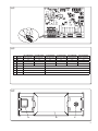
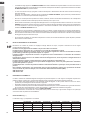
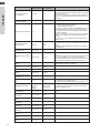
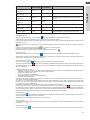
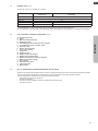
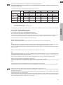
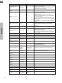
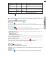
The following table summarises the cables to be used.
ODU/IDU communication cable
A
2 x 0,5 mm2 shielded
DHW and outside air probe cable
B
H03RN-F 2 G 0,5 / H03VV-F 2 G 0,5
INTERNAL UNIT
Power cable
SHERPA AQUADUE SMALL
C
EXTERNAL UNIT
Power cable
D
SHERPA AQUADUE
BIG
3 X H07V-K 4 mm2
OSCEBSH24EI
OSCEBCH36EI
OSCEINH48EI
OSCETNH48EI
OSCEINH60EI
OSCETNH60EI
H07RN-F 3 G2,5
H07RN-F 3 G4
H07RN-F 3 G4
H07RN-F 5 G2,5
H07RN-F 3 G4
H07RN-F 5 G2,5
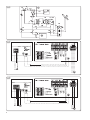
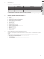
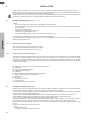
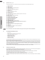
Electrical connections (fig. 20, 21, 22)
Connect the cables listed in the section below to the terminal boards of the internal and external units, referring to fig. 20, 21, 22
and the descriptions below.
ENGLISH
2.9.3
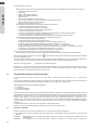
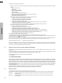
Internal unit:
• terminals L-N- internal unit power supply
• terminals 24-25: outdoor temperature detection probe inlet (required for activating the climate curves, enabling the electrical
heater elements inside the unit or activating an external heat source)
• terminals 26-27: domestic water tank temperature detection probe inlet (required for checking temperature of the domestic
water tank and managing anti-legionella cycles)
• terminals Q-P: communication cable between internal unit and external unit
• terminals N-L-12: 3-way valve for domestic water
• terminals N-13: contactor activation for electrical heater element power supply in domestic water tank during anti-legionella
cycles (220-240V 50Hz 100W max)
• terminals 14-15: activation of external heat source e.g.: gas boiler (contact 8A (3A) 250Vac)
• terminals 16-17: alarm contact (contact 8A (3A) 250Vac)
• terminals 5-L: domestic hot water request (when the domestic hot water tank temperature is set by a dedicated external
control; a closed contact between these terminals activates the domestic hot water request).
• terminal 1 electronic board on/off and cooling remote free contact
• terminal 2 electronic board on/off and heating remote free contact
• terminal 3 electronic board Eco mode remote free contact
• terminal 4 electronic board night-time mode remote free contact
• terminal 5 electronic board domestic water activation remote free contact (already connected to terminal board 5/L)
• terminal 6 electronic circuit board TA remote free contact for enabling cooling or heating
• terminal L electronic board remote free contacts common connection
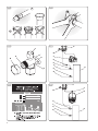
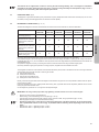
Terminals 1 to L are located on the electronic board; the terminals can be removed from the board to connect them more easily
and then returned to the original position (see fig. 25).
All additional cables must be long enough to enable the electric panel to open.
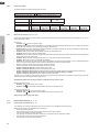
Single-phase external unit:
• terminals L-N- external unit power supply
• terminals Q-Pcommunication cable between internal unit and external unit
Three-phase external unit:
• terminals R-S-T-Nexternal unit power supply
• terminals Q-Pcommunication cable between internal unit and external unit
Fasten all the cables using cable grips
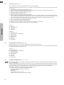
2.10
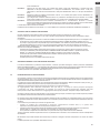
INSTALLATION CHECKS (fig. 9, 14)
2.10.1
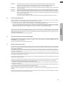
Preparing for initial start-up (fig. 14)
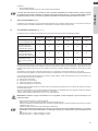
The initial start-up of the air-water heat pump must be carried out by qualified technical personnel.
Before starting up the air-water heat pumps ensure that:
• All safety conditions are met.
• The air-water heat pump has been properly fastened to the support surface.
• The minimum distance has been observed.
• The hydraulic connections have been carried out in accordance with the instruction booklet.
• The hydraulic system has been charged and bled.
• The hydraulic circuit on/off valves are open
50