1
2
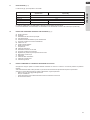
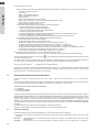
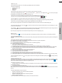
The minimum nominal diameter of the hydraulic connecting pipes must be 1”.
To allow the maintenance and repair operations it is indispensable that each hydraulic connection is fitted with respective manual closing valves.
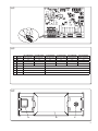
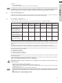
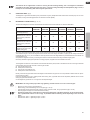
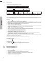
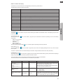
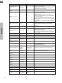
The table below shows the characteristics the hydraulic system must have.
Unit
Nominal water
flow*
System water
content
Operating
pressure
System height
difference
OS-CEBSH24EI
OS-CEBCH36EI
OS-CEINH48EI
I.U. SHERPA SMALL
OS-CETNH48EI
OS-CEINH60EI
OS-CETNH60EI
I.U. SHERPA BIG
l/s
0,31
0,52
0,62
0,62
0,69
0,79
l
l
23
400
38
400
45
400
45
400
51
400
58
400
Max
kPa
300
300
300
300
300
300
Max
m
20
20
20
20
20
20
Min
Max**
Circulation of the air conditioning system minimum content must be guaranteed even with the valves on the system closed.
*
**
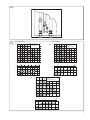
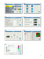
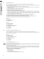
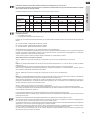
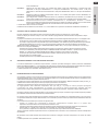
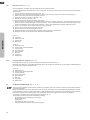
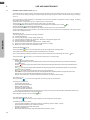
The graphs in fig. 18 show the head, for each hydraulic circulator speed, available to the hydraulic connections of the internal unit.
A Main circuit – Constant differential pressure
B Main circuit – Variable differential pressure
C Domestic hot water circuit - Variable differential pressure
Sherpa Aquadue is equipped with two high efficiency circulation pumps.
The pumps with permanent magnet wet rotors have an electronic control module with integrated frequency converter. There is
a control knob on the regulation module. The DHW pump is fitted with a LED indicator to show the pump running status.
All functions can be set, enabled or disabled using the control knob.
Settings using the control knob
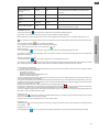
Mode A – Variable differential pressure (Δp-v) (available on air conditioning circuit pump and DHW pump).
The differential-pressure set point is increased linearly over the permitted volume flow range between ½ H and H (Δp-v graph).
The differential pressure generated by the pump is adjusted to the corresponding differential-pressure set point.
This control mode is especially useful in heating systems with fan coils and radiators, since the flow noise at the thermostatic
valves is reduced.
Mode B - Constant differential pressure (Δp-c) (available on air conditioning circuit pump).
The differential pressure set point H is constantly maintained, within the permitted delivery range, at the programmed set point
up to the maximum characteristic curve (Δp-c graph).
This regulation method is recommended for floor mounted heating systems or older heating systems with large pipelines, but
also for all other applications that do not have variable characteristic curves, such as for example DHW boiler pumps.
Mode C – Constant revolutions I,II,III (available on DHW pump).
The circulation pump works like a traditional three-speed pump but with lower power absorption.
The main circulation pump for the cooling/heating circuit can be set in modes A or B, the DHW circuit pump can be set in modes
B or C.
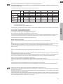
The graphs below show the head available to the hydraulic connections of the internal unit.
The first two graphs refer to the circulation pump for the cooling/heating circuit, the second two are for the DHW circuit pump.
Check that the system’s pressure losses guarantee the required water flow (see sect. 2.10.2).
If greater heads are required due to high pressure losses in the system, an inertial vessel or a hydraulic separator and an external
idle pump must be added.
The system must have a minimum water content required to ensure good system operation. If it is insufficient, add a storage
vessel in order to reach the required content.
The water distribution pipes must be suitably insulated with expanded polyethylene or similar materials. The on/off valves, bends
and unions must also be suitably insulated. To prevent air locks inside the circuit, insert automatic or manual breather devices at
all the points (high pipes, traps etc.) where air may accumulate.
47
ENGLISH
for systems at ground level
with maximum system water temperature 35°C