1
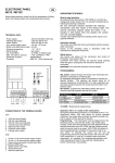
ELECTRONIC PANEL MC15 GB Single-phase electronic control unit for the automation of sliding gates, doors and barriers with incorporated radio receiver. Possibility of integrating a radio system with the control unit operating as a safety device, composed of an RTX 2278 “Base” transceiver (fitted onto the control unit itself) and a maximum of two battery-operating RTX 2252 “Sensor” transceivers to connect mechanical and 8.2 kohm-resistive safety edges, generally positioned on the mobile part of the gate. TECHNICAL DATA: - Power supply - Flashing light output : 230 Vac 50-60Hz 8W max. : 230 Vac 50Hz 100W Resistive Load max. 50W Inductive Load max. - Motor output : 230 Vac 50-60Hz 750 W max. - Services power supply output : 24 Vac 6 W max. - Safety devices and controls in BT : 24 Vdc - Operating temperature : -10 55 °C - Radio receiver : 433 MHz - Op. transmitters : 12-18 Bit or Rolling Code - Max. TX codes in memory : 120 (CODE or PED CODE) - Board dimensions : 108x138 mm. TERMINAL BOARD CONNECTIONS: CN1 : 1 : Grounding Connection. 2 : Grounding Connection. CN2 : 1 : 230 Vac line input (Phase). 2 : 230 Vac line input (Neutral) 3 : 230 Vac Flashing light Output (Neutral). 4 : 230 Vac Flashing light Output (Phase). 5 : Opening 230V Motor Output. 6 : Common 230V Motor Output. 7 : Closing 230V Motor Output. OPERATING FEATURES: Step-by-step operation: By using either the radio-control ( CODE led on ) or the low voltage buttons to activate the gate, you obtain the following action: the first impulse activates the opening mechanism until the motor time expires or the opening limit switch is reached, the second impulse closes the gate. If an impulse is sent before the motor time expires or one of the two end runs are reached, the control unit will stop both opening and closing movements. An additional control re-starts motion in the opposite direction. CN3: 1 : Photocell Control and Power Supply ( 24Vac 6W ). 2 : Photocell Control and Power Supply (GND). 3 : Step-by-step control Button Input / Open (NO). 4 : Blocking Device Input (NC) / Button Close (NO). 5 : Common GND input 6 : Safety device input (NC). 7 : Motor Opening Limit Switch Input (NC). 8 : Common GND input. 9 : Motor Closing Limit Switch Input (NC). 10: Antenna Ground Input. 11: Antenna hot Pole Input. Automatic closing : The control unit closes the gate automatically without sending additional commands. The choice of this operating mode is described in the instructions for setting the delay period. Pedestrian Passage: The control unit allows, using either the radio-control (P. CODE led on) or the Pedestrian button, the Motor to run for a programmable amount of time. CN4: 1 : Aux power supply +24Vdc. 2 : Output 4 Open Collector 100mA Max Load. 3 : Output 3 Open Collector 100mA Max Load. 4 : Output 2 Open Collector 100mA Max Load. 5 : Output 1 Open Collector 100mA Max Load. Blocking Device Input : The control unit allows the blocking button connection (NC). Tripping during any operating phase of the control unit causes movement to stop immediately. An additional movement control will be valid as long as you have disabled the blocking input, and, in any case, the unit will carry out the opening stage automatism with pre-flashing for 5 seconds. If the automation is fully open, in this case, it will carry out the closing phase. Attention: Jumper this input if not used. CN5: 1 : Motor Encoder Power Supply + 24Vdc. 2 : Motor Encoder Signal Input. 3 : GND Motor Encoder Power Supply. Photocells: The control unit allows Photocells to be powered and connected in accordance with directive EN 12453. - DS Input (NC) 1 rev. 1.3 03/05/2013 Photocell operation is ignored during opening, whereas during closing they will reverse the direction of movement. To provide operation that meets EN 13849-1 Category 2, a test is carried out on the photocells prior to every manoeuvre. The control unit will only start the manoeuvre if the test is passed: otherwise the control unit will not enable any movement, and for every command all of the programming leds will flash, signalling an alarm situation. Opening and Closing Limit Switch: The control unit allows the Opening and Closing Limit Switch connection (NC). When it is triggered during the respective operating phases, movement stops immediately. Attention: Leave these inputs free if not used. Motor Power and Speed adjustment: The electronic control unit is equipped with a VR1 trimmer to adjust motor Power and Speed, fully managed by the microprocessor. The adjustment can be made within a range of 50% and 100% of the Maximum Power. Nevertheless, every movement has an initial surge, powering the motor for 2 seconds at the maximum power even if motor power adjustment is enabled. Attention: You will need to repeat the teach-in phase if you wish to adjust the VR1 trimmer as operation and deceleration times may be affected. Obstacle detection: The electronic control unit is equipped with a VR2 trimmer to adjust the Counter Power required to detect the obstacle, fully managed by the microprocessor. The adjustment can be made by setting a time interval between a minimum of 0.1 seconds and a maximum of 3 seconds. Note: by setting the VR2 trimmer at the minimum, the obstacle detection function is excluded. Attention: - When limit switches are connected to the control unit, the detection of an obstacle always causes the motor to change direction during the closing phase, and also during the opening phase, for 2 seconds. - When no limit switches are connected to the control unit, the detection of an obstacle always causes the motor to change direction during the closing phase (except for the last 5 seconds of the operation when it performs a Stop) and to change direction for 2 seconds during the opening phase(except for the last 5 seconds of the operation when it performs a Stop). Motor Encoder: The control unit can have an Encoder integrated to the Motor. Encoders can be used by the control unit for its Obstacle Detection function to guarantee greater precision when operations are being carried out. Deceleration: The motor deceleration function is used on the gates to stop them from reaching their final position at a high speed in the opening and closing phases. The control unit allows deceleration to be programmed for the desired points (before the gates are completely open or closed) during Motor Timer programming (see Main menu). If you are using the "Automatic programming" function (see menu 2) it is also possible to include a deceleration phase (see Main menu). Operation with TIMER: The control unit can have a timer set up instead of an openclose control button. Example: at 08:00 the timer closes the contact and the control unit opens the gate. At 18:00 the timer opens the contact and the control unit closes the gate. During the interval between 08:00 and 18:00, at the end of the opening phase, the control unit disables the flashing beacon, automatic closing and radio controls. Open Collector OUT 1-4 Output Operation: The control unit has 4 open collector outputs to manage auxiliary functions: Out 1: Out 1 will be active in flash mode, only during the Opening phase. Out 2: Out 2 will be active in flash mode, only during the Closing phase. Out 3: Out 3 will be steadily active, only during the Pause phase. Out 4: Out 4 will be steadily active, only when the gate is closed. Integration of the RTX 2278 - RTX2252 safety system. By installing module RTX 2278 on the control unit, it is automatically possible to use, via radio, the functions of the safety system composed of transceiver RTX 2278 (Base) and a maximum of 2 RTX 2252 transceivers (Sensor 1 and Sensor 2). For more details on system operation, see paragraphs “RTX 2278 Base” and “RTX 2252 Sensor”. Before starting any operation, the control unit carries out a test to make sure module RTX 2278 is working correctly; this fulfils EN 13849-1 Category 2 operation. Commands from Sensor 1 are ignored during opening, whereas during closing they will reverse the direction of movement. Commands from Sensor 2 will stop movement in both closing and opening phases. PROGRAMMING : The SEL key:this selects the type of function to be memorised, which is indicated by a flashing Led. Repeatedly press the key to select the desired function. The selection will remain active for 10 seconds, indicated by a flashing Led. If no other operations are carried out during this time, the control board will return to its previous state. The SET key: this programs the information according to the type of function previously selected with the SEL button. IMPORTANT: The SET key function can also be replaced by the radio-control, if previously programmed (CODE led on). MAIN MENU The control unit is provided by the manufacturer with the possibility of selecting a number of important functions. ---------------------- MAIN MENU ----------------Led Reference Led off Led On 1) CODE No code Code entered 2) CODE PED. No code Code entered 3) IN.CMD.AP. Disabled Enabled 4) LAMP/CORT. Flashing Courtesy Light 5) PGM. AUT. PGM Automatic=OFF PGM Automatic=ON 6) T. MOT. Motor time 30 sec. Programmed time 7) T.MOT.PED. Mot. Time Ped. 10 sec. Programmed time 8) T. PAUSA: No auto close With auto close 1) CODE: (Radio-control code) The control unit allows up to 120 radio-controls to be memorised with different types of fixed or rolling codes. Programming. The transmission code is programmed in the following way: use the SEL key to move to the flashing CODE LED, at the same time send the pre-selected code from the radio-control you wish to use; when the CODE LED stays on steadily, programming is finished. If all 120 available codes have been memorised, by repeating the programming operation, all programming LEDs will start to flash, indicating that it is not possible to memorise any more codes. 2 rev. 1.3 03/05/2013 During programming it is possible to use the radio-control key located on the control unit, instead of the SET key, only if previously memorised. Deletion. Memorised codes can be deleted in the following way: press the SEL key, the CODE LED will start flashing, then press the SET key, the CODE LED will switch off and the procedure is finished. 7) T. MOT. PED: (Programming a pedestrian operating time of 4 minutes max.) The control unit is factory supplied with a predefined Pedestrian Motor operating time of 10 sec. without deceleration. If it is necessary to modify the pedestrian operating time, programming must be carried out when the gate is closed, as follows: use the SEL key to move to the flashing T.MOT PED. LED, then press the SET key briefly. The Motor will start the Opening cycle; press the SET key again at the point where you wish to start deceleration: the T. MOT. PED. LED will start flashing at a slower rate and the Motor will decelerate; when it reaches the required point, press the SET key to finish the Opening cycle. At this point the T. MOT PED. LED will start flashing at its standard pace again and the Motor will begin the Closing phase; repeat the above operations for the Closing phase. If you do not want the control unit to decelerate, when the opening and closing phase is finished, press the SET key twice during programming, instead of just once. During programming it is possible to use the radio-control key located on the control unit, instead of the SET key, only if previously memorised. 2) CODE PED:(Code for the Ped./ S Door radio-control The programming and deleting procedure is the same as the one illustrated above except that the selected Led should be forPEDESTRIAN CODE. 3) INB. CMD. AP: (Command inhibition during opening and pause time, if entered) The command inhibition function during opening and pause time, if entered, is used when automation includes a loop detector. During the opening or pause phase the control unit does not consider the commands sent by the loop detector with every passage. The factory settings of the control unit have disabled command inhibition during opening and pause time. If it is necessary to enable it, do the following: use the SEL key to move to the flashing INB.CMD.AP LED then press the SET key. The INB.CMD.AP LED will light up steady. Repeat the procedure if you wish to restore the previous configuration. 4) LAMP/CORT. : (Selection of the flashing light or the courtesy light) The control unit has a 230 Vac output, for connection to a flashing light or a courtesy light. The control unit is supplied by the manufacturer with the Flashing function enabled. If you wish to enable the flashing beacon function, including during pauses, proceed as follows: using the SEL key to move to the LAMP/CORT flashing LED then press the SET key, and the LAMP/CORT flashing LED will switch on steady. Repeat the operation if you wish to restore the factory setting. If you wish to enable the courtesy light, repeat the operation described above, pressing the SEL button twice instead of once (making the LAMP/CORT LED flash rapidly). Repeat the operation if you wish to restore the factory setting. 8) T. PAUSA (PAUSE T.): (Automatic closing time programming max. 4 minutes) The control unit is factory supplied without automatic closing. If you wish to enable automatic closing, proceed as follows: using the SEL key to move to the flashing T. PAUSA LED, press the SET key briefly, then wait for the amount of time you wish to set for automatic closing; briefly press the SET key again, and in that moment the automatic closing time will be memorised and the T. PAUSA LED will stay on steady. If you wish to restore the initial condition (without automatic closing), move to the flashing T. PAUSA LED, then press the SET key twice within 2 seconds. The Led will switch off and the operation will be finished. During programming it is possible to use the radio-control key located on the control unit, instead of the SET key, only if previously memorised. 5) PGM. AUT. : (Automatic Programming): With this control unit it is possible to carry out Automatic Programming ( SIMPLIFIED). First, move the gates to their half-way position, press the SEL button until the PGM. AUT. LED flashes and then press and hold the SET button down. The control unit completes the Auto programming phase by executing a complete opening and closing phase (hold the SET key down until Auto Programming is finished). At the same time, the Deceleration cycle is automatically configured at 15% of the complete cycle. During Automatic Programming, you can use the radio-control key on the control unit instead of the SET key, only if previously memorised. EXTENDED MENU 1 The control unit is supplied by the manufacturer with the possibility of directly selecting the main menu functions only. If you wish to enable the functions described in Extended Menu 1, proceed as follows: press and hold the SET button for 5 seconds, after which amount of time the T. MOT. PED and T. PAUSA LEDs will start flashing alternately. The user then has 30 seconds to select the functions for Extended Menu 1 from the SEL and SET buttons. After another 30 seconds the control unit will go back to the main menu. 6) T. MOT and DECELERATION: (Programming a motor operation ---------------------- time of max 4 minutes) EXTENDED MENU 1 ----------------- Led Reference Led Off Led On A) CODE Step-by-Step Inverting B) CODE PED Electronic Brake = OFF Electronic Brake= ON C) IN.CMD.AP. Anti-collision=OFF Anti-collision APCH or CH=ON D) LAMP/CORT. Deceleration = OFF Deceleration = ON E) PGM. AUT. Follow Me = OFF Follow Me = ON F) T.MOT. Encoder = OFF Encoder = ON G) T. MOT.PED. Alternate ON/OFF flashing light H) T. PAUSA Alternate ON/OFF flashing light The control unit is factory supplied with a predefined motor operating time of 30 sec. without deceleration. If it is necessary to modify the motor operating time, programming must be carried out when the gate is closed, as follows: use the SEL key to move to the flashing T.MOT LED, then press the SET key briefly. The Motor will begin its opening cycle. When it starts the initial point of deceleration, press the SET key again. At the same time, the motor will decelerate until it reaches the required position. Press the SET key to finish the opening cycle. The T. MOT LED will then start flashing quickly. Now repeat motor time programming and the deceleration operation for the closing cycle. If you do not want the control unit to decelerate, when the opening and closing phase is finished, press the SET key twice during programming, instead of just once. A) CODE ( Step-by-Step / Automatic Operation ) : The control unit is supplied by the manufacturer with Automatic mode disabled. If you wish to enable the function, proceed as follows: make sure that you have enabled extended menu 1 3 rev. 1.3 03/05/2013 (reported by alternately flashing T. MOT PED Leds and T. PAUSA Led), by using the SEL key to select the flashing CODE LED, and then press the SET key. At this point the CODE LED lights up steady and programming is finished. Accordingly, using either the radio-control or the low voltage push button panel to operate the gate, you will obtain the following function: the first impulse controls opening until the motor time expires, the second impulse controls gate closing. If an impulse is sent before the motor time expires, the control unit changes the direction of motion in the opening and closing phases. Repeat the procedure if you wish to restore the previous configuration. complete. Repeat the procedure if you wish to restore the previous configuration. F) T. MOT. ( ENCODER ) : The control unit supplied by the manufacturer can manage Motors with a point Encoder; in the default configuration, Encoder point control is disabled. If you wish to enable the control, proceed as follows: check that Extended Menu 1 is enabled (T. MOT. PED and T. PAUSA LEDs start flashing alternately), use the SEL button to move to the flashing T. MOT. LED then press the SET key: at that point the T. MOT LED will light up steady and programming is complete. Repeat the procedure if you wish to restore the previous configuration. B) PED. CODE ( Electronic Brake ) : The control unit is supplied by the manufacturer with the electronic brake function disabled. If you wish to enable the function, proceed as follows: check that Extended Menu 1 is enabled (T. MOT. PED and T. PAUSA LEDs start flashing alternately), use the SEL button to move to the flashing PED CODE LED then press the SET key: at that point the PED CODE LED will light up steady and programming is complete. Accordingly, the control unit slows down gate advancement by inertia, when there is a stop or command to change the direction of motion. Repeat the procedure if you wish to restore the previous configuration. EXTENDED MENU 2 The control unit is supplied by the manufacturer with the possibility of directly selecting the main menu functions only. If you wish to enable the functions described in Extended Menu 2, proceed as follows: access Extended Menu 1 (as described in the relative paragraph), then press and hold the SET button down again for 5 seconds, after which amount of time the T. MOT. PED and T. PAUSA LEDs will start flashing simultaneously. The user then has 30 seconds to select the functions for Extended Menu 2 using the SEL and SET buttons. After another 30 seconds the control unit will go back to the main menu. C) INB. CMD. AP ( Anti-collision Function ) : The control unit is supplied by the manufacturer with the Anticollision (pedestrian) Function disabled. If you wish to enable the function, proceed as follows: check that Extended Menu 1 is enabled (T. MOT. PED and T. PAUSA Leds flash simultaneously), use the SEL button to move to the flashing INB. CMD. AP. LED and then press the SET button. At this point the INB. CMD. AP. LED will light up steady and programming is complete. The control unit will now operate in Anti-Collision (pedestrian) mode. If you wish to enable the Anti-Collision (pedestrian) function for the closing phase only, repeat the operation described above, pressing the SEL key twice (making the IN.CMD.AP. LED flash quickly). Repeat the procedure if you wish to restore the previous configuration. ---------------------- EXTENDED MENU 2 ----------------- Led Reference Led Off Led On A) CODE remote PGM = OFF remote PGM = ON B) PED. CODE Photocell Test = OFF Photocell Test= ON C) IN.CMD.AP. Sens1 = rev. in CH Sens1 = brief rev. AP/CH D) LAMP/CORT.Sens2 =stop AP/CH Sens2 = brief rev. AP/CH E) PGM. AUT. PUL=PUL – BL=BL PUL=AP - BL=PED F) T.MOT. PUL=PUL – BL=BL PUL=AP - BL=CH G) T. MOT. PED. Simultaneous ON/OFF flashing H) T. PAUSA Simultaneous ON/OFF flashing A) CODE ( Remote radio-control programming ) : The control unit allows the transmission code to be programmed, without using the SEL button directly on the control unit, but remotely. The Radio-control can be remotely programmed as follows: continuously sending a previously-memorised radio-control code for more than 10 seconds. At this point the control unit switches to programming mode, as described above for the CODE LED in the main menu. The control unit is factory supplied with the remote transmission code programming function disabled. If you wish to enable the function, proceed as follows: check that Extended Menu 2 is enabled (T. MOT. PED and T. PAUSA LEDs flash simultaneously), use the SEL button to move to the flashing CODE LED, then press the SET key: at this point the CODE LED will light up steady and programming is complete. Repeat the procedure if you wish to restore the previous configuration. B) CODE PED. (Photocell Test) : The control unit is factory supplied with Photocell Test programming disabled. If you wish to enable the function (in accordance with Standard EN 12453), proceed as follows: check that Extended Menu 2 is enabled (T. MOT. PED and T. PAUSA Leds flash simultaneously), use the SEL button to move to the flashing CODE PED. LED then press the SET key: at this point the CODE PED. LED will light up steady and programming is complete. Accordingly, the Safety Device test will be carried out before the automation starts any type of motion. Repeat the procedure if you wish to restore the previous configuration. When the Safety Device inputs are not in use they must be jumpered and the Photocells Test deactivated. C) IN.CMD.AP. ( Sensor 1 Operating Logic) : The control unit is factory supplied with the following operating logic installed for Sensor 1 operation: it is not considered if it is triggered in the opening phase, whereas in the closing phase it D) LAMP/CORT. ( Deceleration ): As mentioned above, it is possible to programme a deceleration phase on the control unit for opening or closing, whereas deceleration is automatically enabled with the Automatic Programming function. If you do not wish to implement any deceleration, it can be excluded: therefore, if you are using Automatic Programming, the Deceleration phase will not be enabled, whereas if you are using Motor Time Programming, as you are programming you will not be given the possibility of programming deceleration during the opening and closing phases. If, prior to excluding deceleration, it was programmed from the Motor Time Programming function, it will be necessary to repeat programming all over again. If you wish to exclude deceleration, proceed as follows: make sure Extended Menu 1 is enabled (reported by T.MOT.PED and T. PAUSA Leds flashing alternately). Using the SEL key, move to the flashing LAMP/CORT. LED and then press the SET key: the LAMP/CORT. will turn off definitely and programming will be complete. Repeat the procedure if you wish to restore the previous configuration. E) PGM. AUT. ( Follow Me ) : It is possible to set the "Follow Me" function on the control unit: this function can only be programmed if a Pause Time has already been programmed, and it is used to shorten the Pause time to 5 sec after the photocell disengages, i.e. the gate closes 5 seconds after the user has passed through. If you wish to enable the function, proceed as follows: check that Extended Menu 1 is enabled (T. MOT. PED and T. PAUSA Leds flash simultaneously), use the SEL button to move to the flashing PGM. AUT. LED and then press the SET key: the PGM. AUT. LED will light up steady and programming is 4 rev. 1.3 03/05/2013 causes a change in direction, if, naturally, module RTX 2278 is installed on the control unit. If you wish to change the operating logic so that Sensor 1 causes the system to stop, followed by a brief change in direction to release the obstruction, in either the opening or the closing phase, do the following: make sure Extended Menu 2 is enabled (T.MOT.PED. and T. PAUSA leds flash simultaneously), use the SEL key to move to the flashing IN.CMD.AP LED and then press the SET key: the IN.CMD.AP LED will light up steadily and programming will be complete. Repeat the operation to restore the initial configuration. Level Leds On 1 CODE 2 CODE – CODE PED. 3 CODE – CODE PED. – IN.CMD.AP. 4 CODE – CODE PED. – IN.CMD.AP. – LAMP/CORT. 5 CODE – CODE PED. – IN.CMD.AP. – LAMP/CORT. – PGM.AUT. 6 CODE – CODE PED.– IN.CMD.AP. – LAMP/CORT. – PGM.AUT. – T.MOT. Slowing Programming The control unit allows you to programme the power used to carry out the slowing phase. It is possible to choose between 6 different levels of power: every combination of lit Leds corresponds to a level according to the table above; in other words, starting from the lowest led (LED CODE) and moving upwards, each Led corresponds to a higher power level. Using the SEL key it is possible to scroll through the different power levels; for every selected power level, the highest respective Led will flash (for example, if level 4 is selected the CODE, CODE PED. and IN.CMD.AP. leds light up steady, whereas the LAMP/CORT led will flash); press SET to confirm. Level 3 is selected in the default configuration. D) LAMP/CORT. (Sensor 2 Operating Logic) : The control unit is factory supplied with the following operating logic installed for Sensor 2 operation: when it is triggered it causes the gate to stop in both opening and closing phases, if, naturally, module RTX 2278 is installed on the control unit. If you wish to change the operating logic so that Sensor 2 causes the system to stop, followed by a brief change in direction to release the obstruction, in either the opening or the closing phase, do the following: make sure Extended Menu 2 is enabled (T.MOT.PED. and T. PAUSA Leds flash simultaneously), use the SEL key to move to the flashing LSMP/CORT. LED and then press the SET key: the LAMP/CORT. LED will light up steady and programming will be complete. Repeat the operation to restore the initial configuration. RESET : To reset the default configuration of the control unit, press the SEL and SET buttons simultaneously; all RED signal Leds will switch on and then immediately off again. E) PGM. AUT. ( PUL operation = P/P and BL = PED. ) : The control unit is factory supplied with PUL control input operation for the connection of a cyclical primary control button (NO) and a BL input for the connection of a Blocking Device (NC). If you wish to select another operating mode for the PUL and BL inputs, proceed as follows: check that Extended Menu 2 is enabled (T.MOT.PED. and T. PAUSA LEDs start flashing simultaneously), use the SEL button to move to the flashing PGM.AUT. LED then press the SET key: at that point the PGM.AUT. LED will light up steady and programming is complete. Accordingly, the PUL input can be used for the connection of a cyclical primary control button (NO), while the BL input will be used to connect a button (NO) for the Pedestrian cycle alone. Repeat the procedure if you wish to restore the previous configuration. DIAGNOSTICS : Photocell Test : The control unit is designed for the connection of safety devices that comply with point 5.1.1.6 of standard EN 12453. The Safety Device and Block tests are carried out with every operating cycle. If there is no connection and/or the control unit is not working, it will not enable gate movement, and will visually report the failed test by making all of the Led signal lights flash at the same time. Once the photocells are running correctly again, the control unit is ready for normal operation. This ensures monitoring against failures, in compliance with EN 954-1, Category 2. F) T. MOT. ( PUL Operation = Opens and BL = Closes ) : The control unit is factory supplied with PUL control input operation for the connection of a cyclical primary control button (NO) and a BL input for the connection of a Blocking Device (NC). If you wish to select another operating mode for the PUL and BL inputs, proceed as follows: check that Extended Menu 2 is enabled (T.MOT.PED. and T. PAUSA LEDs start flashing simultaneously), use the SEL button to move to the flashing T. MOT. LED then press the SET key: at that point the T. MOT. LED will light up steady and programming is complete. Accordingly, the PUL input makes it possible to connect a button (NO) for the Opening phase only, and the BL input to connect a button (NO) for the Closing phase only. Repeat the procedure if you wish to restore the previous configuration. Control input test: On each low voltage control input, the control unit uses a LED signal to make the status readily known. Operating logic: when a LED is on it means the input is closed, when a LED is off it means the input is open. EXTENDED MENU 3 The control unit is supplied by the manufacturer with the possibility of directly selecting the main menu functions only. If you wish to enable the programming of the slowing power carried out by the control unit, proceed as follows: access Extended Menu 2 (as described in the relative paragraph), then press and hold the SET button down again for 5 seconds, after which amount of time the T. MOT. PED and T. PAUSA LEDs will first flash alternately and then simultaneously. The user then has 30 seconds to select the slowing power using the SEL and SET buttons. After, another 30 seconds the control unit will go back to the main menu. ---------------------- EXTENDED MENU 3 RTX 2278 MODULE (BASE) It is possible to select four different operating frequencies, all within the 868 MHz band. ----------------5 rev. 1.3 03/05/2013 The selected operating frequency must be set in the same manner on either the memorised RTX2278 (Base) or the RTX 2252 (Sensor) devices. Use Dip Switch SW1 on both the RTX 2278 and RTX 2252 devices to make the selection. SW1 SW1 SW1 Led Reference Led Off 1) SENSOR 1 CODE Battery OK LOW 2) SENSOR 2 CODE Battery OK LOW Flashing Led Battery Battery In terms of the PROGRAMMING MENU, on the other hand, please refer to the paragraph on "Programming Keys and Signal Leds". SW1 Check the Preselected Operating Frequency FREQUENCY A FREQUENCY B FREQUENCY C Before programming the transmission code for RTX 2252 (Sensor) Transceivers combined with a RTX 2278 (Base) Transceiver, it is necessary to select one of the four available frequencies (see the "Operating Frequency Selection" paragraph). It is then advisable to make sure that the preselected band is free (not already in use by another device). To carry out this check, do the following: using the SET key, move to the PROGRAMMING MENU; the Base scans the preselected frequency and if it is already occupied by the Base the MONITOR LED and PROGR. MENU LEDs will flash alternately. In this case proceed to select a different frequency (on both the Base and Sensor). If, on the other hand, the selected frequency is free, proceed with programming the Sensors associated with each channel, as described below. FREQUENCY D Technical Data - Power supply: - Max. consumption: - Operating frequency: - RTX 2252 Sensors that can be stored: - Operating temperature: - Dimensions: 5Vdc 25 mA 868 MHz FSK band 2 -10°C ÷ 55°C 59x39 mm. Programming Keys and Signal Leds The SEL key: this selects the type of function to be memorised, the selection is indicated by a flashing LED. Repeatedly press the key to select the desired function. The selection will remain active for 15 seconds indicated by a flashing LED, after which time the device will return to its original state. SET Key: - this is used to choose between the Monitor Menu and the Programming Menu: if the SEL and SET keys are not used, the Monitor Menu will be automatically selected after 1 minute of inactivity. - this programs the function selected using the SEL key. TERMINAL BOARD CONNECTIONS: CN1 : 1 : Antenna Hot Pole Input. 2 : Antenna Ground Input. Signal Led Led on: option memorised. Led off: option not memorised. Flashing led: selected option. Description of Operation The RTX 2278 (Base) device controls one, or at most, two RTX 2252 (Sensor) devices, through radio-frequency, for the connection of sensitive edges. It is possible to view two menus with the RTX 2278 (Base) Device: MONITOR MENU ---------------------- PROGRAMMING MENU ----------------Led Reference Led Off Led On 1) SENSOR 1 CODE No Pgm. code SENSOR 1 Pgm. 2) SENSOR 2 CODE No Pgm. code SENSOR 2 Pgm . PROGRAMMING MENU With the MONITOR MENU and an acoustic signal (Buzzer), the Device reports the following information: ALARM SIGNAL: Led on + Acoustic signal. This lets you know which one of the memorised RTX 2252 devices the alarm refers to. A short Beep sounds every time a reference Led lights up. 1) SENSOR 1 CODE ( Programming for transceiver RTX 2252 Sensor no. 1) Programming for the transmission code of Transceiver RTX 2252 (Sensor) no. 1 combined with a RTX 2278 (Base) Transceiver must be carried out as follows: press the SEL key, the SENSOR 1 CODE LED will start flashing; in this phase the Base communicates in broadcast mode with all installed sensors, looking for one that can be memorised: press the SET key for the Sensor you wish to memorise to send the memorisation confirmation code ( the TX LED of the Sensor will flash quickly 5 times); the SENSOR 1 CODE LED will stay on steady and programming is finished. The Base device exits programming if no confirmation code is received within 15 seconds. ---------------------- MONITOR MENU ----------------Led Reference Led Off Led On 1) SENSOR 1 CODE No Alarm SENSOR 1 Alarm 2) SENSOR 2 CODE No Alarm SENSOR 2 Alarm LOW BATTERY SIGNAL: Led On (brief flashes) + Acoustic signal. This lets you know which one of the memorised RTX 2252 devices has low batteries. In addition to the acoustic signal whenever a reference Led lights up, two brief Beeps also sound every minute. Deletion: The memorised code can be deleted as follows: press the SEL key, the SENSOR 1 CODE LED will start flashing. Press the SET key, the SENSOR 1 CODE LED will switch off, and the procedure is finished. 2) SENSOR 2 CODE ( Programming for transceiver RTX 2252 Sensor no. 2) ---------------------- MONITOR MENU ----------------- 6 rev. 1.3 03/05/2013 To programme the transmission code for RTX 2252 (Sensor) Transceiver no. 2 combined with an RTX 2278 (Base) Transceiver, proceed as described in point "2) SENSOR 1 CODE". The RTX 2252 Device allows NC (normally closed contact) standard type or 8K2 resistance type sensitive edges to be connected. Use Dip Switch SW2 No. 1 to make the selection: DIP 1 = OFF NC input operation (default). DIP 1 = ON 8K2 input operation. RESET SW2 If the device must be reset to factory configuration, keep the SEL and SET keys simultaneously pressed down for more than 2 seconds so that all signal LEDs briefly switch on at the same time accompanied by three quick Buzzer Beeps. RTX 2252 (Sensor) NC 8K2 Transmission Mode Selection With the RTX 2252 (Sensor) Transceiver device it is possible to select two different operating modes, "Normal" or "Low Power". The difference in operation consists in the Sensor transmitting power. In "Low Power" operating mode the transmitting power of the Sensor is considerably lower; in terms of energy savings, which translates into longer battery life, it is necessary, however, to take into account the subsequent reduction in radio capacity for installation. Use Dip Switch SW2 No. 2 to make the selection: DIP 2 = OFF : "Low Power" operating mode disabled (default). DIP 2 = ON : "Low Power" operating mode enabled. Technical Data - Battery power supply: - Operating frequency: - System capacity in open field: - Operating temperature: - Dimensions: - Container: SW2 2 x 1.5Vdc Alkaline (AA) 868 MHz FSK band 1020 m max. -1055°C 120x80x50mm. ABS UL94V-0 ( IP56 ) SW2 SW2 CN1 Terminal Board Connections CN1: 1 2 3 4 LP=OFF : Safety Device Input (NC) or 8K2 : Safety Device Input (NC) or 8K2. : Inhibitor Input (NC). : Inhibitor Input (NC). LP=ON Inhibitor Input Operating Mode With the RTX 2252 (Sensor) Device it is possible to connect an (NC) contact to temporarily inhibit the sensitive edge installed on it. ATTENTION! When not in use, the inhibitor input must always be jumpered. Description of Operation The RTX 2252 (Sensor) device allows NC (normally closed contact) standard type or 8K2 resistance type sensitive edges to be connected, normally installed on the mobile part of the gate. It only works in combination with the control Base. The device is battery-operated so as to exclude any type of cable connection. Once it is memorised (see "RTX 2278 - Programming Keys and Signal Leds" paragraph) it can send the following information to the RTX 2278 (Base) device: Survival signal: this is used to periodically check the correct radio connection between the devices. Alarm signal: this is used to inform the base that the safety device is operating. Low battery signal: this is used to inform the system of the battery level. Low Battery Signal Discharged battery levels are reported by the TX LED flashing quickly on the RTX 2252 (Sensor) Device. The same information is also sent to RTX 2278 (Base) device, that reports the event with visual and acoustic warnings. ATTENTION! We recommend replacing the device batteries as soon as the TX LED starts flashing. ATTENTION -For best performance, change the 1.5V (AA) alkaline batteries annually. - To change the batteries, open the Sensor container with a screwdriver. -Dispose of the used batteries in appropriate waste containers. ATTENTION! If the RTX 2252 Device (Sensor) is dismantled from an installation, it is advisable to take the batteries out so that the Sensor no longer continues unnecessary transmission. NC or 8K2 Operating Mode Selection 7 rev. 1.3 03/05/2013 IMPORTANT FOR THE INSTALLER The control unit does not have any type of isolating device for the 230 Vac line. It is therefore the responsibility of the installer to set up an isolating device inside the system. It is necessary to install an omnipolar switch, surge category III. It must be positioned to provide protection from accidental closing, pursuant to point 5.2.9 of EN 12453. The various electrical components external to the control unit must be cabled in accordance with standard EN 60204-1 as amended, and as set forth in point 5.2.7 of EN 12453. The power supply cables can have a maximum diameter of 14 mm; the power supply and connecting cables must be set up through the assembly of cable glands, supplied as “optional”. For the power supply cables, use flexible cables in an insulating sheath in harmonised polychloroprene (H05RN-F) with a minimum conductor section of 1mm2 Be careful when drilling holes in the outside casing to pass connecting and power supply cables through, and when assembling the cable glands, that everything is installed so as to maintain the IP protection characteristics of the panel as unchanged as possible. Also be sure to set up the cables so that they are firmly anchored. The rear part of the casing is equipped with fittings for wall mounting (it is possible to drill holes for installation with plugs, or there are already holes available for installation with screws). Plan and implement all necessary measures to achieve an installation that does not alter the IP protection. Push button panels for manual control must be assembled by positioning the push button panel in a location where the user is not in a dangerous position. The gear motor used to move the gate must comply with the requirements of point 5.2.7 of EN 12453. The photocell control and power supply output must be dedicated to the power supply of the photocells only. It cannot be used for other applications. With every operation cycle, the control unit performs the photocell operating test, ensuring protection against the rupture of Category 2 crush-proof devices, in accordance with point 5.1.1.6. of EN 12453. Accordingly, if the safety devices are not connected and/or are not working, the control unit is not enabled for operation. For correct radio receiver operation, if one or more control units are being used, it is advisable to install them with a minimum distance of at least 3 metres between them. The RTX 2278-RTX 2252 radio system is designed to help the installer automate gate operation in compliance with Machinery Directive 2006/42/EC. The installer must make sure that the automation system fulfils all of the requirements set forth in EN 12453 and EN 12445. IMPORTANT FOR THE USER - The device must never be used by children or persons with reduced physical-psychological abilities, unless supervised or trained to operate it and instructed in its modes of use. - Do not allow children to play with the device and keep the radio-controls away from their reach. - ATTENTION: keep this instruction manual safe and observe the important safety requirements contained herein. Failure to comply with the requirements may cause damage and serious accidents. - Frequently examine the system to detect any signs of damage. Do not use the device if it is in need of repair work. Attention All operations which require opening the casing (connecting cables, programming, etc.) must be carried out by expert personnel during installation. For any additional operation that requires the casing to be re-opened (re-programming, repairs or amendments to installation) contact the after-sales assistance. Declaration of Conformity Electronic Control Unit: MC15 + RTX 2278 comply with the specifications of the Directives R&TTE 99/5/EC, EMC 2004/108/EC, LVD 2006/95/EC. 8 rev. 1.3 03/05/2013