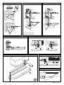
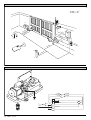
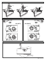
1
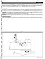
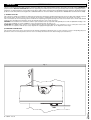
D811292 ver.02 14-02-03 I AUTOMAZIONI A BRACCIO PER CANCELLI A BATTENTE GB ARM AUTOMATIONS FOR SWING GATES 8 027908 171542 JOINT ISTRUZIONI D'USO E DI INSTALLAZIONE INSTALLATION AND USER'S MANUAL Via Lago di Vico, 44 36015 Schio (VI) Tel.naz. 0445 696511 Tel.int. +39 0445 696533 Fax 0445 696522 Internet: www.bft.it E-mail: [email protected] D811292_02 2 - JOINT - Ver. 02 D811292_02 MANUALE D'USO ITALIANO Nel ringraziarVi per la preferenza accordata a questo prodotto, la ditta è certa che da esso otterrete le prestazioni necessarie al Vostro uso. Leggete attentamente l’opuscolo “AVVERTENZE” ed il “LIBRETTO ISTRUZIONI” che accompagnano questo prodotto in quanto forniscono importanti indicazioni riguardanti la sicurezza, l’installazione, l’uso e la manutenzione. Questo prodotto risponde alle norme riconosciute della tecnica e della disposizioni relative alla sicurezza. Questo prodotto risponde alle norme riconosciute della tecnica e della disposizioni relative alla sicurezza. Confermiamo che è conforme alle seguenti norme: CAN/CSA-C22.2 No. 247-92 UL Std. No. 325 (Certificato 1002906 in data 16 ottobre 2000). 1) GENERALITÀ Attuatore adatto per uso residenziale. Progettato per cancelli a battente con pilastri di notevoli dimensioni. Il braccio di azionamento, con particolare forma anti-cesoiamento, consente di movimentare ante quando l'attuatore è notevolmente spostato dal fulcro delle stesse. Il motoriduttore elettromeccanico irreversibile, mantiene il blocco in chiusura ed apertura. La leva di sblocco, presente in ogni attuatore e situata all'interno di uno sportello con chiave personalizzata, consente di effettuare la manovra manuale con estrema facilità. Condensatore e micro di finecorsa sono montati e collegati a bordo del motore. Joint può essere montato a destra o a sinistra fissando opportunamente il motoriduttore alla staffa di ancoraggio. ATTENZIONE! L’operatore JOINT non è dotato di regolazione meccanica di coppia. È obbligatorio utilizzare un quadro di comando del medesimo costruttore, conforme ai requisiti essenziali di sicurezza e dotato di adeguata regolazione elettrica della coppia. ATTENZIONE! L’installazione, la manutenzione e la riparazione, devono essere eseguite solo da persone responsabili, professionalmente preparate ed istruite sulle norme di sicurezza vigenti. È vietata qualsiasi operazione di manutenzione dell’automatismo con alimentazione elettrica inserita. 2) MANOVRA DI EMERGENZA La manovra di emergenza può essere eseguita dall’interno agendo nell’apposita leva di ogni operatore come in fig.1 e spingendo manualmente il pannello. Per riattivare il funzionamento motorizzato, riposizionare la leva nella posizione iniziale e richiudere lo sportello dotato di chiave personalizzata. Fig. 1 JOINT - Ver. 02 - 3 USER’S MANUAL Thank you for buying this product. Our company is sure that you will be more than satisfied with the product’s performance. Carefully read the “WARNINGS” pamphlet and the “INSTRUCTION BOOKLET” which are supplied together with this product, since they provide important information regarding the safety, installation, use and maintenance of the product. This product complies with recognised technical standards and safety regulations. We declare that this product is in conformity with the following directives: CAN/CSA-C22.2 No. 247-92 UL Std. No. 325 (Certificate: 1002906 Date Issued: October 16, 2000). 1) GENERAL OUTLINE This controller is suitable for residential use and has been designed for swing gates with particularly large gate posts. The drive arm, built with a special anti-shearing shape, allows the leaves to be moved when the controller is considerably out of place with respect to the fulcrum of the leaves. The non-reversible electro-mechanical gearmotor maintains the stop during closing and opening. The release lever, fitted in each controller and situated inside the door fitted with personalised key, allows the manual manoeuvre to be easily carried out. WARNING! The installation, the maintenance and the repair should be done by responsible and qualified persons with an updated knowledge of the current safety standards. It’s strictly forbidden to service the automation when the power is on. ATTENTION! The JOINT model controller is not equipped with mechanical torque adjustment. It is compulsory to use a control panel of the same manufacturer, in compliance with the basic safety requirements equipped with appropriate electric adjusment of the torque. 2) EMERGENCY MANOEUVRE The emergency manoeuvre can be carried out form the inside by activating the appropriate lever on each controller, as in fig.1, and pushing the panel by hand. To restore motorised operation, turn the lever to its initial position and close the hatch having a personalised key. Fig. 1 4 - JOINT - Ver. 02 D811292_02 ENGLISH D811292_02 MANUALE PER L’INSTALLAZIONE Nel ringraziarVi per la preferenza accordata a questo prodotto, la ditta è certa che da esso otterrete le prestazioni necessarie al Vostro uso. Leggete attentamente l’opuscolo “AVVERTENZE” ed il “LIBRETTO ISTRUZIONI” che accompagnano questo prodotto in quanto forniscono importanti indicazioni riguardanti la sicurezza, l’installazione, l’uso e la manutenzione. Questo prodotto risponde alle norme riconosciute della tecnica e della disposizioni relative alla sicurezza. Confermiamo che è conforme alle seguenti norme: CAN/CSA-C22.2 No. 247-92 UL Std. No. 325 (Certificato 1002906 in data 16 ottobre 2000). 1) SICUREZZA GENERALE ATTENZIONE! Una installazione errata o un uso improprio del prodotto, può creare danni a persone, animali o cose. • Leggete attentamente l’opuscolo ”Avvertenze” ed il ”Libretto istruzioni” che accompagnano questo prodotto, in quanto forniscono importanti indicazioni riguardanti la sicurezza, l’installazione, l’uso e la manutenzione. • Smaltire i materiali di imballo (plastica, cartone, polistirolo, ecc.) secondo quanto previsto dalle norme vigenti. Non lasciare buste di nylon e polistirolo a portata dei bambini. • Conservare le istruzioni per allegarle al fascicolo tecnico e per consultazioni future. • Questo prodotto è stato progettato e costruito esclusivamente per l’utilizzo indicato in questa documentazione. Usi non indicati in questa documentazione potrebbero essere fonte di danni al prodotto e fonte di pericolo. • La Ditta declina qualsiasi responsabilità derivante dall’uso improprio o diverso da quello per cui è destinato ed indicato nella presente documentazione. • Non installare il prodotto in atmosfera esplosiva. • La Ditta declina qualsiasi responsabilità dall’inosservanza della Buona Tecnica nella costruzione delle chiusure (porte, cancelli, ecc.), nonché dalle deformazioni che potrebbero verificarsi durante l’uso. • Togliere l’alimentazione elettrica, prima di qualsiasi intervento sull’impianto. Scollegare anche eventuali batterie tampone se presenti. • Prevedere sulla rete di alimentazione dell’automazione, un interruttore o un magnetotermico onnipolare con distanza di apertura dei contatti uguale o superiore a 0.11 in (3mm). • Verificare che a monte della rete di alimentazione, vi sia un interruttore differenziale con soglia da 0.03A. • Verificare se l’impianto di terra è realizzato correttamente: collegare tutte le parti metalliche della chiusura (porte, cancelli, ecc.) e tutti i componenti dell’impianto provvisti di morsetto di terra. • La Ditta declina ogni responsabilità ai fini della sicurezza e del buon funzionamento dell’automazione se vengono impiegati componenti di altri produttori. • Usare esclusivamente parti originali per qualsiasi manutenzione o riparazione. • Non eseguire alcuna modifica ai componenti dell’automazione se non espressamente autorizzata dalla Ditta. • Istruire l’utilizzatore dell’impianto per quanto riguarda i sistemi di comando applicati e l’esecuzione dell’apertura manuale in caso di emergenza. • Non permettere a persone e bambini di sostare nell’area d’azione dell’automazione. • Non lasciare radiocomandi o altri dispositivi di comando alla portata dei bambini onde evitare azionamenti involontari dell’automazione. • L’utilizzatore deve evitare qualsiasi tentativo di intervento o riparazione dell’automazione e rivolgersi solo a personale qualificato. • Tutto quello che non è espressamente previsto in queste istruzioni, non è permesso. INSTALLARE L’APRICANCELLO SOLO QUANDO: • L’attuatore risulta idoneo per la tipologia costruttiva del cancello e per la classe di utilizzo del cancello. • Tutti i punti di schiacciamento evidenti sono protetti o schermati. • L’apricancello è concepito per essere installato solo su cancelli utilizzati per il passaggio di veicoli. Per i pedoni devono essere previsti accessi separati. • Il cancello deve essere installato in una posizione tale da garantire una distanza sufficiente tra il cancello e le strutture adiacenti durante l’apertura e la chiusura, al fine di ridurre il rischio di intrappolamento. I cancelli a battente non potranno essere aperti in aree di pubblico accesso. • Il cancello deve essere installato correttamente e deve funzionare liberamente in entrambe le direzioni prima dell’installazione dell’apricancello. Non serrare eccessivamente la frizione dell’attuatore o la valvola di sfiato della pressione per rimediare ad un cancello danneggiato. ITALIANO IN CASO DI APRICANCELLI CON COMANDO UOMO PRESENTE: • I comandi dell’apricancello devono essere posizionati in modo tale che l’utilizzatore abbia una visuale completa dell’area del cancello quando il cancello è in movimento. • Dovrà essere posizionato vicino ai comandi un cartello recante la scritta “AVVERTENZA” dalle lettere alte almeno 0.25 in (6,4 mm.) e la seguente dichiarazione: “ Il cancello in movimento è in grado di causare lesioni o morte - non azionate il cancello quando il percorso non è libero”. • Non dovranno essere utilizzati dispositivi di chiusura automatici (quali temporizzatori, rilevatori di spira o dispositivi similari). • Non dovrà essere collegato nessun altro dispositivo di attivazione. I comandi devono essere sufficientemente lontani dal cancello in modo che l’utente non possa venire a contatto con il cancello quando utilizza tali comandi. I comandi previsti per il resettaggio dell’attuatore dopo due attivazioni successive del dispositivo/i contro l’intrappolamento devono essere posizionati sulla linea visiva del cancello. I comandi esterni o facilmente accessibili dovranno essere dotati di protezione al fine di impedirne l’utilizzo non autorizzato. I segnali di avvertenza e i cartelli devono essere installati in una posizione visibile nell’area del cancello. IN CASO DI ATTUATORI CHE UTILIZZANO UN SENSORE CON RILEVAMENTO SENZA CONTATTO: • Leggere le istruzioni sul posizionamento dei sensori senza contatto per ogni tipo di applicazione. • Provvedere affinché venga ridotto al minimo il rischio di intervento di disturbi come quando, ad esempio, il veicolo fa scattare il sensore mentre il cancello è ancora in movimento. • Posizionare uno o più sensori senza contatto dove esiste il rischio di intrappolamento o ostruzione, ad esempio lungo il perimetro raggiunto dal cancello in movimento. IN CASO DI ATTUATORI CHE UTILIZZANO UN SENSORE CON RILEVAMENTO A CONTATTO (COSTA SENSIBILE O EQUIVALENTE): • • • Dovranno essere installati uno o più sensori di contatto sul punto di serraggio di cancelli verticali a cardine per passaggio veicolare. Dovrà essere installato un sensore con contatto a circuito permanente i cui cablaggi dovranno essere disposti in modo tale che la comunicazione tra il sensore e l’apricancello non sia soggetta a danni meccanici. Dovrà essere installato un sensore con contatto senza fili quale ad esempio un sensore che trasmette segnali di frequenze radio (RF) all’apricancello per le funzioni di protezione contro l’intrappolamento nei casi in cui la trasmissione dei segnali non sia ostacolata o impedita dalla struttura dell’edificio, dal paesaggio naturale o da ostacoli similari. Il sensore con contatto senza fili dovrà funzionare conformemente alle condizioni per l’utilizzo finale previste. IMPORTANTI PRESCRIZIONI DI SICUREZZA ATTENZIONE: al fine di ridurre il rischio di danni fisici o morte: • Leggere e osservare tutte le istruzioni. • Non permettere ai bambini di utilizzare o giocare con i comandi del cancello. Tenere il telecomando fuori dalla portata dei bambini. • Tenere lontani oggetti e persone dal cancello. NON E’ PERMESSO ATTRAVERSARE IL PERCORSO ESEGUITO DAL CANCELLO IN MOVIMENTO. • Controllare mensilmente il corretto funzionamento del cancello. Il cancello DEVE invertire marcia in caso di contatto con oggetti rigidi e deve fermarsi quando un oggetto attiva i sensori senza contatto. Dopo aver regolato la forza o il finecorsa, ricontrollare l’apricancello. La mancata regolazione e l’omissione del successivo controllo dell’apricancello possono aumentare il rischio di danni fisici e di morte. • Utilizzare lo sblocco di emergenza solo a cancello fermo. • ESEGUIRE UNA MANUTENZIONE REGOLARE DEL CANCELLO. Leggere il manuale dell’utilizzatore. Eventuali riparazioni alle parti meccaniche del cancello devono essere eseguite da personale qualificato. • L’entrata è riservata ai veicoli. Prevedere un’entrata separata per i pedoni. • Conservare le presenti istruzioni. 2) GENERALITÀ Attuatore adatto per uso residenziale. Progettato per cancelli a battente con pilastri di notevoli dimensioni. Il braccio di azionamento, con particolare forma anti-cesoiamento, consente di movimentare ante quando l'attuatore è JOINT - Ver. 02 - 5 MANUALE PER L’INSTALLAZIONE notevolmente spostato dal fulcro delle stesse. Il motoriduttore elettromeccanico irreversibile, mantiene il blocco in chiusura ed apertura. La leva di sblocco, presente in ogni attuatore e situata all'interno di uno sportello con chiave personalizzata, consente di effettuare la manovra manuale con estrema facilità. Condensatore e micro di finecorsa sono montati e collegati a bordo del motore. Joint può essere montato a destra o a sinistra fissando opportunamente il motoriduttore alla staffa di ancoraggio. ATTENZIONE! L’operatore JOINT non è dotato di regolazione meccanica di coppia. È obbligatorio utilizzare un quadro di comando del medesimo costruttore, conforme ai requisiti essenziali di sicurezza delle direttive e dotato di adeguata regolazione elettrica della coppia. ATTENZIONE! L’installazione, la manutenzione e la riparazione, devono essere eseguite solo da persone responsabili, professionalmente preparate ed istruite sulle norme di sicurezza vigenti. È vietata qualsiasi operazione di manutenzione dell’automatismo con alimentazione elettrica inserita. 3) DATI TECNICI Tensione: ................................................................... 120V ±10% 50Hz (*) Motore: ....................................................................... Monofase 1400 min-1 Potenza: ............................................................................................. 300W Assorbimento: ..................................................... 1.7A (230V); 3,4A (120V) Condensatore: .............................. 10µF 450V (230V); 40µF 250V (120V) Classe isolamento: .................................................................................... F Protezione termica: ............................ 266°F ........... (130°C) autoripristino Lubrificazione: ............................................................. Grasso permanente Rapporto di riduzione: ....................................................................... 1÷812 Giri in uscita: .......................................................................... 1.7 min-1 max Albero uscita: ................................................................ Albero cavo 20X20 Tempo di apertura 90°: ......................................................................... 15s Coppia fornita: ...................... 320Nm (~32kgm)........236.01lbf/ft (~70.54lb) Peso e lunghezza max anta: per lunghezza anta 2.5m ....... 2000N (~200kg)........449.61 lbf (~440.92lb) per lunghezza anta 2m .......... 2500N (~250kg).........562.02lbf (~551.15lb) Reazione all’urto: ..................... Frizione elettrica (con quadro di comando) Trasmissione del moto: ........................................................ Braccio a leve Arresto: ......................................................... Finecorsa elettrici incorporati Manovra manuale: ............................. Sportello con chiave personalizzata Numero di manovre in 24h: ................................................................... 100 Condizioni ambientali: ................... -15 ÷ +60 C..........................°59÷140°F Grado di protezione: ........................................................................... IP 44 Peso attuatore: ............ 160N (~16kg) 35.96 lbf .........................(~35.27 lb) Dimensioni: .................................................................................. Vedi fig.1 * Tensioni speciali di alimentazione a richiesta. Nel caso il motore giri in senso inverso, invertire i morsetti di marcia del motore “M”. Per il collegamento della centralina, fare riferimento al rispettivo manuale istruzioni. 4) INSTALLAZIONE DELL’AUTOMAZIONE Verifiche preliminari Controllare che: - Che la struttura del cancello sia sufficientemente robusta e rigida. La posizione di fissaggio deve essere valutata secondo la struttura dell'anta. In ogni caso, il braccio di manovra deve spingere in un punto dell'anta rinforzato (fig.2). - Che le ante si muovano manualmente per tutta la corsa. Se il cancello non è di nuova installazione, controllare lo stato di usura di tutti i componenti. Sistemare o sostituire le parti difettose o usurate. L'affidabilità e la sicurezza dell'automazione è direttamente influenzata dallo stato della struttura del cancello. 5) FISSAGGIO PIASTRA DI SUPPORTO (Fig.2) L'attuatore viene fornito completo di staffa di fissaggio e braccio a leve. Identificato il punto di rinforzo dell'anta, a cancello chiuso, tracciare una linea orizzontale immaginaria dal centro del rinforzo fino al pilastro (fig.2). Posizionare la staffa di ancoraggio rispettando le quote in fig.2 per aperture fino a 90° o come in fig.3 per aperture superiori a 90° fino a max 125°. La superfice del pilastro, dove viene fissata la staffa, deve essere piana e pararallela all'anta. Utilizzare viti o tappi ad espansione adeguati al tipo di pilastro. Nel caso la superficie del pilastro sia irregolare, adottare dei tasselli ad espansione con prigionieri in modo da poter regolare la staffa di fissaggio parallela all'anta (fig.4). - Fissare il motoriduttore alla piastra con le 4 viti orientando il motoriduttore come destro o sinistro (fig.5). - Assemblare il braccio a leve come in fig.6. DX = montaggio su anta destra. SX = montaggio su anta sinistra. Scegliere la posizione della staffa "F" più idoneo al fissaggio all'anta. - Infilare il quadro del braccio nel'albero di uscita del motoriduttore e 6 - JOINT - Ver. 02 - - - fissarlo (fig.7). Sbloccare l'attuatore azionando la leva di sblocco per permettere il movimento agevolato del braccio (vedere paragrafo "MANOVRA DI EMERGENZA"). La posizione corretta che deve assumere il braccio dell'attuatore, è quella rappresentata in fig.8. Il punto di attacco all'anta "A", si individua posizionando il braccio in modo da rispettare la quota rappresentata in fig.8. Fissare l'angolare di trascinamento "A" all'anta mediante saldatura o con viti. Con attuatore sbloccato, verificare il corretto movimento del braccio. Ripetere la stessa operazione per l'altra anta. 6) PREDISPOSIZIONE IMPIANTO ELETTRICO Predisporre l'impianto elettrico come indicato in fig.9. È importante mantenere separati i collegamenti di alimentazione dai collegamenti di servizio (fotocellule, costa sensibile ecc.). La sezione ed il numero di collegamenti è indicato in fig.9. ATTENZIONE! Per il collegamento alla rete, utilizzare cavo multipolare del tipo previsto dalle normative (UL1015). In fig.10 è riportata la morsettiera di collegamento dell'attuatore e la posizione dove fissare il pressacavo che deve essere bloccato con adeguato serraggio. Nel caso il motore giri in senso inverso, invertire i morsetti di marcia del motore "M". Per il collegamento della centralina, fare riferimento al rispettivo manuale istruzioni. 7) REGOLAZIONE FINECORSA - Togliere la copertura dei finecorsa. - Identificare i finecorsa secondo fig.12 per l’attuatore “DX” e secondo fig.11 per l’attuatore “SX”. - A cancello completamente chiuso ed aperto, ruotare la camma fino a percepire lo scatto del micro di finecorsa interessato e bloccarla in posizione fissando la vite. - Verificare il corretto intervento dei finecorsa e rimontare la protezione precedentemente asportata. - Montare il cofano di copertura . - Se la centralina di comando, prevede la regolazione del tempo di lavoro, questo deve essere regolato ad un valore leggermente superiore all’intervento dei finecorsa dell’attuatore. 8) REGOLAZIONE SFASAMENTO ANTE Nel caso di cancello a due ante il quadro di comando deve prevedere la regolazione del ritardo in chiusura della seconda anta per consentire la corretta sequenza di chiusura. Per il cablaggio del motore che deve chiudere in ritardo, consultare le istruzioni del quadro di comando installato. 9) REGOLAZIONE COPPIA MOTORE La regolazione di coppia del motore (antischiacciamento), viene regolata dal quadro di comando. Vedere il manuale istruzione della centralina di comando. La regolazione deve essere tarata per la minima forza necessaria ad effettuare la corsa di apertura e chiusura completa e comunque entro i limiti previsti dalle norme vigenti. ATTENZIONE! Una regolazione di coppia eccessiva, può compromettere la sicurezza antischiacciamento. Al contrario, una regolazione di coppia insufficiente, può non garantire una corsa di apertura o chiusura corretta. 10) MANOVRA DI EMERGENZA La manovra di emergenza può essere eseguita dall’interno agendo nell’apposita leva di ogni operatore come in fig.13 e spingendo manualmente il pannello. Per riattivare il funzionamento motorizzato, riposizionare la leva nella posizione iniziale e richiudere lo sportello dotato di chiave personalizzata. 11) VERIFICA DELL’AUTOMAZIONE Prima di rendere definitivamente operativa l'automazione, controllare scrupolosamente quanto segue: - Controllare il corretto funzionamento di tutti i dispositivi di sicurezza (micro-finecorsa, fotocellule, coste sensibili ecc.). - Verificare che la spinta (antischiacciamento) dell'anta sia entro i limiti previsti dalle norme vigenti. - Verificare il comando di apertura manuale. - Verificare l'operazione di apertura e chiusura con i dispositivi di comando applicati. - Verificare la logica elettronica di funzionamento normale e personalizzata. 12) USO DELL’AUTOMAZIONE Poichè l’automazione può essere comandata a distanza mediante radiocomando o pulsante di Start, è indispensabile controllare frequentemente la perfetta efficienza di tutti i dispositivi di sicurezza. Per qualsiasi D811292_02 ITALIANO D811292_02 MANUALE PER L’INSTALLAZIONE ITALIANO anomalia di funzionamento, intervenire rapidamente avvalendosi di personale qualificato. Si raccomanda di tenere i bambini a debita distanza dal raggio d’azione dell’automazione. 13) COMANDO L’utilizzo dell’automazione consente l’apertura e la chiusura della porta in modo motorizzato. Il comando può essere di diverso tipo (manuale, con radiocomando, controllo accessi con badge magnetico, ecc.) secondo le necessità e le caratteristiche dell’installazione. Per i vari sistemi di comando, vedere le relative istruzioni. Gli utilizzatori dell’automazione devono essere istruiti al comando e all’uso. 14) MANUTENZIONE Per qualsiasi manutenzione, togliere alimentazione al sistema. - Lubrificare periodicamente le superfici di strisciamento del braccio telescopico. - Eseguire saltuariamente la pulizia delle ottiche delle fotocellule. - Far controllare da personale qualificato (installatore) la corretta regolazione della frizione elettrica. - Per qualsiasi anomalia di funzionamento non risolta, togliere alimentazione al sistema e chiedere l’intervento di personale qualificato (installatore). Nel periodo di fuori servizio, attivare lo sblocco manuale per consentire l’apertura e la chiusura manuale. 15) DEMOLIZIONE ATTENZIONE ! Avvalersi esclusivamente di personale qualificato. L’eliminazione dei materiali va fatta rispettando le norme vigenti. Nel caso di demolizione dell’automazione non esistono particolari pericoli o rischi derivanti dall’automazione stessa. È opportuno, in caso di recupero dei materiali, che vengano separati per tipologia (parti elettriche - rame - alluminio plastica - ecc.). 16) SMANTELLAMENTO ATTENZIONE ! Avvalersi esclusivamente di personale qualificato. Nel caso l’automazione venga smontata per essere poi rimontata in altro sito bisogna: - Togliere l’alimentazione e scollegare tutto l’impianto elettrico esterno. - Nel caso alcuni componenti non possano essere rimossi o risultino danneggiati, provvedere alla loro sostituzione. Le descrizioni e le illustrazioni del presente manuale non sono impegnative. Lasciando inalterate le caratteristiche essenziali del prodotto, la Ditta si riserva di apportare in qualunque momento le modifiche che essa ritiene convenienti per migliorare tecnicamente, costruttivamente e commercialmente il prodotto, senza impegnarsi ad aggiornare la presente pubblicazione. JOINT - Ver. 02 - 7 INSTALLATION MANUAL Thank you for buying this product. Our company is sure that you will be more than satisfied with the product’s performance. Carefully read the “WARNINGS” pamphlet and the “INSTRUCTION BOOKLET” which are supplied together with this product, since they provide important information regarding the safety, installation, use and maintenance of the product. This product complies with recognised technical standards and safety regulations. We declare that this product is in conformity with the following directives: CAN/CSA-C22.2 No. 247-92 UL Std. No. 325 (Certificate: 1002906 Date Issued: October 16, 2000). 1) GENERAL SAFETY WARNING! An incorrect installation or improper use of the product can cause damage to persons, animals or things. • The “Warnings” leaflet and “Instruction booklet” supplied with this product should be read carefully as they provide important information about safety, installation, use and maintenance. • Scrap packing materials (plastic, cardboard, polystyrene etc) according to the provisions set out by current standards. Keep nylon or polystyrene bags out of children’s reach. • Keep the instructions together with the technical brochure for future reference. • This product was exclusively designed and manufactured for the use specified in the present documentation. Any other use not specified in this documentation could damage the product and be dangerous. • The Company declines all responsibility for any consequences resulting from improper use of the product, or use which is different from that expected and specified in the present documentation. • Do not install the product in explosive atmosphere. • The Company declines all responsibility for any consequences resulting from failure to observe Good Technical Practice when constructing closing structures (door, gates etc.), as well as from any deformation which might occur during use. • Disconnect the electrical power supply before carrying out any work on the installation. Also disconnect any buffer batteries, if fitted. • Fit an omnipolar or magnetothermal switch on the mains power supply, having a contact opening distance equal to or greater than 3mm. • Check that a differential switch with a 0.03A threshold is fitted just before the power supply mains. • Check that earthing is carried out correctly: connect all metal parts for closure (doors, gates etc.) and all system components provided with an earth terminal. • Fit all the safety devices (photocells, electric edges etc.) which are needed to protect the area from any danger caused by squashing, conveying and shearing, according to and in compliance with the applicable directives and technical standards. • Position at least one luminous signal indication device (blinker) where it can be easily seen, and fix a Warning sign to the structure. • The Company declines all responsibility with respect to the automation safety and correct operation when other manufacturers’ components are used. • Only use original parts for any maintenance or repair operation. • Do not modify the automation components, unless explicitly authorised by the company. • Instruct the product user about the control systems provided and the manual opening operation in case of emergency. • Do not allow persons or children to remain in the automation operation area. • Keep radio control or other control devices out of children’s reach, in order to avoid unintentional automation activation. • The user must avoid any attempt to carry out work or repair on the automation system, and always request the assistance of qualified personnel. • Anything which is not expressly provided for in the present instructions, is not allowed. INSTALL THE GATE OPERATOR ONLY WHEN: • The operator is appropriate for the construction of the gate and the usage Class of the gate. • All openings of horizontal slide gat are guarded or screened from the bottom of the gate to a minimun of 4 fet (1,2 m) above the fround to prevent a 2-1/4 inch (57,15 mm) diameter sphere from passing trough the openings anywhere in the gate, and in that portion of the adjacent fence the gate covers in the open position. • All exposed pinch points are eliminated or guarded. • Guarding i s supplied for exposed rollers. 8 - JOINT - Ver. 02 • • • The operator is intended for installation only on gates used for vehicles. Pedestrians must supplied with a separate access opening. The gate must be installed in a location so that enough clearance is supplied between the gate and adjacent structures when opening and closing to reduce the risk of entrapment. Swinging gates shall not open into public access areas. The gate must be properly installed and work freely in both directions prior to the installation of the gate operator. Do not over-tighten the operator clutch or presure relief valve to compensate for a damaged gate. FOR GATE OPERATOR WITH HOLD-TO-RUN CONTROL: • The gate operator controls must be placed so that the user has full view of the gate area when the gate is moving, • A sign with the message “WARNING” must be positioned near the controls. The characters for the writing should be at least 6.4 mm high. The following statement should also be indicated: “Moving Gate Has the Potential of Inflicting Injury or Death - Do Not Start Gate Unless Path is Clear” • An automatic closing device (such as a timer, loop sensor, or similare device) shall not be employed. • No other activation device shall be connected. Controls must be far enough from the gate so that the user is prevented from coming in contact with the gate while operating the controls. controls intended to be used to reset an operator after 2 sequential activations of the entrapment protection device or devices must be located in the line-of-sight of the gate. Outdoor or easly accesible controls shall have a security feature to prevent unauthorized use. All warnings signs and placards must be installed where visible in the area of the gate. FOR GATE OPERATOR PROVIDED WITH SENSOR FOR CONTACTFREE DETECTION: • • • See instructions on the placement of non contact sensor for each type of application, Care shall be exercised to reduce the risk of nuisance tripping, such as when a vheicle, trips the sensor while the gate is still moving, and One or more non-contact sensor shall be located where the risk of entrapment or obstruction exist, such as the perimeter reachable by a moving gate or barrier. FOR GATE OPERATOR PROVIDED WITH CONTACT DETECTION (RUBBER SKIRT OR SIMILAR): • On or more contact sensor shall be located at the pinch point of a vehicular vertical pivot gate. • A hardwired contact sensor shall be located and its wiring arranged so that the communication between the sensor and the gate operator is not subjected to mechanical damage. • A wireless contact sensor such as one that transimts radio frequency (RF) signals the gate operator for entrapment protection functions shall be located where the transimission of the signals are not obscrtucted or impeded y building structure, natural landscaping or similar obstruction. A wireless contact sensor shall function under the intended end-use conditions. IMPORTANT SAFETY INSTRUCTIONS WARNINGS: to reduce the risk of injury or death: • Read and follow all instructions. • Never let children operate or play with gate control. Keep the remote control away from children. • Always keep people and objects away from the gate. NO ONE SHOULD CROSS THE PATH OF THE MOVING GATE. • Test the gate operator montly. The gate MUST reverse on contact with a rigid object activates the non-contact sensor. After adjusting the force or the limit of travel, reset the gate operator. Failure to adjust and retest the gate operator properly can increase the risk of injury or death. • Use the emergency realease only when the gate is not moving. • KEEP GATES PROPERLY MAINTAINED. Read the owners manual. Have a qualified service person make repairs to gate hardware. • The entrance is for veichles only. Pedestrians must use separate entrance. • Save these instructions. D811292_02 ENGLISH D811292_02 INSTALLATION MANUAL 2) GENERAL OUTLINE This controller is suitable for residential use and has been designed for swing gates with particularly large gate posts. The drive arm, built with a special anti-shearing shape, allows the leaves to be moved when the controller is considerably out of place with respect to the fulcrum of the leaves. The non-reversible electro-mechanical gearmotor maintains the stop during closing and opening. The release lever, fitted in each controller and situated inside the door fitted with personalised key, allows the manual manoeuvre to be easily carried out. WARNING! The installation, the maintenance and the repair should be done by responsible and qualified persons with an updated knowledge of the current safety standards. It’s strictly forbidden to service the automation when the power is on. ATTENTION! The JOINT model controller is not equipped with mechanical torque adjustment. It is compulsory to use a control panel of the same manufacturer, in compliance with the basic safety requirements of directives 73/23/CEE, 89/336/CEE, 89/37/CEE equipped with appropriate electric adjusment of the torque. 3) TECHNICAL SPECIFICATIONS Voltage: ....................................................................... 120V±10% 50Hz (*) Motor: .................................................................... Single-phase 1400min-1 Power: ................................................................................................ 300W Absorption: ........................................................ 1.7A (230V); 3,4A (120V) Capacitor: ..................................... 10µF 450V (230V); 40µF 250V (120V) Insulation class: ........................................................................................ F Thermal protection: ........................... 266°F ........... (130°C) self-resetting Lubrication: ................................................................... Permanent grease Reduction ratio: ................................................................................. 1/812 Output revs.: .......................................................................... 1.7 min-1max Output shaft: ................................................................. 20x20 hollow shaft Opening time 90°: ................................................................................. 15s Torque provided: ................. 320Nm (~32kgm)........236.01lbf/ft (~70.54lb) Max. leaf weight and length: for 2.5m leaf length ................ 2000N (~200kg)........449.61 lbf (~440.92lb) for 2m leaf length ................... 2500N (~250kg).........562.02lbf (~551.15lb) Impact reaction: ................................... Electric clutch (with control panel) Drive: .......................................................................................... Lever arm Stopping: ...................................................... Built-in electric limit-switches Manual manoeuvre: ........................................ Door with personalised key Number of manoeuvres: ................................................................ 100/24h Working temperature: ................... -15 ÷ +60 C..........................°59÷140°F Protection: ......................................................................................... IP 44 Controller weight: ....... 160N (~16kg) 35.96 lbf .........................(~35.27 lb) Dimensions: .................................................................................. See fig.1 *Special supply voltages on request buckle “M” of the operator. Refer to the relevant instruction manual for connection of the control panel. 4) INSTALLATION OF AUTOMATION Preliminary checks Check: - That the structure of the gate is rigid and strong enough. The fixing position should be assessed according to the structure of the leaf. In any case, the manoeuvring arm must push against a reinforced point in the leaf (fig.2). - That the leaves move manually for the whole of their stroke. If a new gate is not being installed, check whether its components are worn. Repair or replace any worn or damaged parts. Automation reliability and safety are directly influenced by the condition of the gate’s structure. 5) FIXING OF SUPPORTING PLATE (Fig.2) The controller is supplied complete with anchoring bracket and lever arm. Once the reinforcement point of the leaf has been identified with the gate closed, draw an imaginary horizontal line from the centre of the reinforcement point to the gate post (fig.2). Position the anchoring bracket according to the values given in fig. 2 for openings of up to 90° or in fig.3 for openings greater than 90° up to a maximum of 125°. The bracket fixing position must be flat and parallel to the leaf. Use screws or expansion bolts which are suited to the type of gate post. If the surface of the gate post is not regular, use expansion bolts with studs so that the parallel plate of the leaf can be adjusted (fig.4). - Fasten the gearmotor to the gate post using the 4 screws, pointing the gearmotor to the left or the right (fig.5). - Assemble the lever arm as shown in fig.6. DX= assembly on the right leaf SX= assemby on the left leaf Choose the most suitable position of ‘F’ bracket for the fastening to the leaf. - Insert the square of the first lever in the output shaft of the gearmotor and - - ENGLISH fasten it (fig.7). Release the controller by activating the release lever so that the arm can move easily (see the “EMERGENCY MANOEUVRE” paragraph). The correct position for the controller arm is shown in fig.8. The leaf fixing point “A” can be identified by positioning the arm so that it is in accordance with the distance shown in fig.8. Fix the angular towing bar “A” to the leaf by welding or using screws. With the controller released, check the correct movement of the arm. Repeat the same operation for the other leaf, if installed. 6) ELECTRICAL INSTALLATION SET-UP Arrange the electrical installation as shown in fig.9. The power supply connections must be kept separate from the auxiliary connections (photocells, sensitive edge, etc.). Fig.9 shows the crosssection and the number of connections. CAUTION! Connection to the mains must be carried out using the type of multipolar cable specified in the standards (UL1015). In fig.10 you will find the junction-box of the operator and the position of the cable holder which should be fixed with an adequate tightening of the bolt. In case the motor tours in the opposite side, you should invert the running buckle "M" of the operator. Refer to the relevant instruction manual for connection of the control panel. 7) LIMIT SWITCH ADJUSTMENT - Remove the casing of the limit switches. - Identify the limit switches following fig.12 for the right-hand controller and following fig.11 for the left-hand controller. - Adjust the opening and closing cams respectively with the gate completely open and completely closed. - Turn the identified cam until the intercepting limiting microswitch triggers and lock the cam in position by tightening the screw. - Make sure that limit switch intervention is correct and refit the cover which was previously removed. - Fit the casing. - If the control unit has working time adjustment (TW), this should be adjusted to a value which is slightly higher than the intervention of the controller limit switches. 8) ADJUSTMENT OF LEAF PHASE DISPLACEMENT In case of gates with two leaves, the control panel should include a delay setting function on closing of the second leaf to guarantee a correct closing manoeuvre. For the wiring of the motor which should close with a slight delay, refer to the instructions for the control panel installed. 9) MOTOR TORQUE ADJUSTMENT The adjustment of the motor torque (anti-squashing) is performed on the control panel. See control unit instruction manual. The adjustment should be set for the minimum force required to carry out the opening and closing strokes completely observing, however, the limits of the relevant standards in force. CAUTION! Excessive torque adjustment may jeopardise the anti-squash safety function. On the other hand insufficient torque adjustment may not guarantee correct opening or closing strokes. 10) EMERGENCY MANOEUVRE The emergency manoeuvre can be carried out form the inside by activating the appropriate lever on each controller, as in fig.13, and pushing the panel by hand. To restore motorised operation, turn the lever to its initial position and close the hatch having a personalised key. 11) AUTOMATION CHECK Before allowing the automation to be used normally, carry out the following procedure very carefully: - Check the correct functioning of all safety devices (limit microswitches, photocells, sensitive edges etc.). - Check that the thrust (anti-squash) force of the leaf is within the limits set by current regulations. - Check the manual opening command. - Check the opening and closing operations with the control devices in use. - Check the standard and customised electronic functioning logic. 12) AUTOMATION OPERATION Since the automation can be remote-controlled by means of a remote control device or a start button, and so out of sight, the good working order of all the safety devices should be checked regularly. In the event of any anomalous functioning of the safety devices, consult a specialised technician immediately. Keep children at a safe distance from the automation operation area. JOINT - Ver. 02 - 9 INSTALLATION MANUAL 13) CONTROL The automation is used for the power-operated opening and closing of the gate. The control can be of a number of types (manual, remote-controlled, magnetic badge access control, etc.) depending on requirements and the characteristics of the installation. See the specific instructions for the various control systems. Users of the automation must be instructed about its control and operation. 14) MAINTENANCE Disconnect the power supply when carrying out any maintenance operations. - Lubricate the joints of the manoeuvring arm regularly. - Clean the lenses of the photocells every so often. - Have a specialised technician (installer) check the adjustment of the electric clutch. - In the event of any anomalous functioning which cannot be resolved, disconnect the power supply and contact a specialised technician (installer). Whilst the automation is out of order, activate the manual release to allow manual opening and closing. 15) SCRAPPING WARNING! This operation should only be carried out by qualified personnel. Materials must be disposed of in conformity with the current regulations. In case of scrapping, the automation devices do not entail any particular risks or danger. In case of materials to be recycled, these should be sorted out by type (electrical components, copper, aluminium, plastic etc.). 16) DISMANTLING WARNING! This operation should only be carried out by qualified personnel. When the automation system is disassembled to be reassembled on another site, proceed as follows: - Disconnect the power supply and the entire external electrical installation. - In the case where some of the components cannot be removed or are damaged, they must be replaced. The descriptions and illustrations contained in the present manual are not binding. The Company reserves the right to make any alterations deemed appropriate for the technical, manufacturing and commercial improvement of the product, while leaving the essential product features unchanged, at any time and without undertaking to update the present publication. 10 - JOINT - Ver. 02 D811292_02 ENGLISH D811292_02 Fig. 2 Fig. 3 6.18" (157) Fig. 1 3.11" (79) 11.81" max 4.33" (110) 23.62" (600) 122.46" (110) SX 12.40" (315) min 12.40" (315) min 93ß 6.69" (170) 0.78" (20) 5.13" (135) 6.69" (170) (300 max) 7.04" (179) SX 13.70" (348) 3.93" (100) 5.13" (135) 2.75" (70) 10.94" (278) 90ß 180ß 180ß 125ß 125ß 6.69" (170) 27.55" (700) The values between brackets are expressed in millimetres Fig. 4 Fig. 5 SX Fig. 6 DX Fig. 7 S F Fig. 8 DX SX S ) 015 6" (1 39.3 S S JOINT - Ver. 02 - 11 D811292_02 Fig. 9 18 AWG = 1 mm2 16 AWG = 1.5 mm2 AL M S Fre G AW 16 WG 4x A 18 2x 3x1 G AW 8AW 18 4x Fti G RG 58 Fte Q R 2x1 6A CF 2x1 WG 8A WG I 3x1 M 6A WG WG A 6 x1 4 T Fri G AW 18 4x CF Fig. 10 3 2 F1 F2 1 GND F1 F2 L M 230V CM N 12 - JOINT - Ver. 02 M 1 2 3 F2-NC F2-COM F1-NC F1-COM NERO-BLACK MARRONE-BROW CELESTE-SKY M D811292_02 Fig. 11 R - FC2 R - FC1 R - FC1 R - FC2 FC1 FC1 FC1 FC2 FC2 FC2 Fig. 12 Fig. 13 RIGHT LEFT SX (LEFT) DX (RIGHT) OPEN SX FC1 CLOSE DX FC1 CLOSE SX FC2 OPEN DX FC2 Fig. 14 JOINT - Ver. 02 - 13 D811292_02 14 - JOINT - Ver. 02 D811292_02 JOINT - Ver. 02 - 15 BFT S.p.a. ITALIA Via Lago di Vico, 44 36015 Schio (VI) Tel.naz. 0445 696511 Tel.int. +39 0445 696533 Fax +39 0445 696522 Internet: www.bft.it E-mail: [email protected]