1
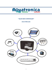
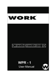
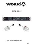
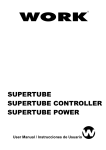
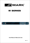
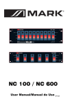
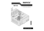
VMX 4
4 DMX INPUTS VIDEO/AUDIO SWITCHER
User Manual / Manual de Instrucciones
Rev 3.0
SAFETY INSTRUCTIONS
EN
CAUTION
RISKOFELECTRICSHOCK
DONOTOPEN
CAUTION:
To reduce the risk of electric shock, do not remove the cover of the device. There is
not serviciable elements inside it. For service purpose, refer to qualified personnel.
WARNING:
In order to reduce the risk of fire or electric shock, do no expose this unit to rain or moisture.
This symbol, alert you the presence of unisolated dangerous voltage inside the enclosure, that can representate
a risk of electric shock.
This symbol alerts you to important operating and maintenance instructions in the accompanying literature.
Detailed Safety Instructions
Read the instructions:
Mains supply:
Moisture:
Hot:
Operating:
Service:
Read all safety and operating instructions before to starting the device by
first time. Keep the user manual for future reference beside the unit.
Follow all instructions and warning inside the user manual and the own
device.
The unit incorporates an IEC/Schuko cable in order to connect to
mains supply. Check that the voltage is correct before to connect the
device. If the protection fuse blows, replace it with a same rate fuse.
In order to avoid the risk of electric shock or fire, not expose the unit to
rain or moisture, using it in dry environments. Also, avoid spill liquidis
inside the unit.
The device must be placed apart from hot sources like radiators,
temperature registers, heating conductions or anythinh heat source.
To avoid damages in the unit, be carefully during the transport, using its
original package and avoiding to place heavy object over it. During its
installations avoid to hit or scratch it. Also, avoid to subject the device to
great vibrations environment.
Switch off the unit and disconnect the main supply after to use it, specially,
during an electric storm. If liquids have been spilled, metallic objects have
entered inside the unit or the device generates smoke or strange smell
and looks like malfunction, switch off it immediately and contact with your
distributor.
This symbol on the product or on its packaging indicates that this product
shall not be trated as household waste. Instead it shall be handed over to
the applicable collection point for the recycling of electrical an electronic
equipment. By ensuring this product is disposed of correctly, you will help
prevent potential negative consequences for the environment and human
health, which could otherwise be caused by inappropriate waste handling
of this product. The recycling of amterials will help to conserve natural
resources. For more detailed information sabout recycling of this product,
please contact your local city office, your household waste disposal service
or the shop where you purchased the product.
VMX 4
User Manual
Page 1
EN
DESCRIPTION
VMX 4 is an audio/video switcher. Its 4 inputs incorporate L+R audio connection. The purpose of this device is to select one
of the 4 input sources and to conduct it to the output. This selection can be made by to ways:
- Through the corresponding frontal push-button.
- Through DMX signal.
On this last case, VMX 4 needs one control DMX channel. Its value will allow to send one of the 4 inputs to the output.
DIMENSIONS
FEATURES
2
483
200
24,3
- Video/Audio multiplexer with 4 inputs.
- Input/Output interface for composite video (luminance +
chrominance + syncronism) and audio (L+R).
- Input source selection through frontal push-button or DMX signal.
- 1 DMX control channel with easy configuration.
- 16x2 characters LCD display
44
435
CONTENTS
Check if the package has been damaged during the transport, if yes, do not use the unit and contact with your dealer.
The package contents is the following:
- VMX 4 (1 unit)
- Schucko-IEC Main Supply cable
VM
X
4
4
DM
X
IN
PU
TS
- User manual
VID
EO
/A
UD
IO
SW
ITC
HE
R
Use
rM
an
ua
l/
Man
ua
l de
Inst
ru
cc
ione
FRONTAL PANEL
s
Re
v 1.0
1
2
3
4
1. Selection push-buttons: Their pushing allow to derivate the pushed input to the output. The corresponding LED will lit showing the assigned input.
The selected input will be showed in the display like CH:CH_X (being X like the pushed input).
2. Display: 16x2 characters LCD display that shows the activated and chosen DMX channel information.
3. DMX channel selection: They allow to select the DMX channel for the switching between inputs.
increase the value and
The number of chosen channel will be showed in the display like ADDR:XXX
(being XXX the channel number).
reduce the value.
4. Power switch ON/OFF
Page 2
User Manual
VMX 4
EN
REAR PANEL
1
2
3
4
1. Mains Supply: Connect the IEC-Schuko cable on this point and in a mains supply outlet with the correct voltage. It incorporates a
protection fuse. In case of fuse blowing, replace it by an identical rate.
2. DMX signal input: 3-pin XLR 3 pin connection. It allows to connect the device to a DMX network and, through one DMX channel,
to switch the chosen video input to the output.
3. Composite Video + Audio output interface: RCA standard connection. The yellow color connector is for video signal. The white
and red connectors are for audio signal (L+R).
4. Composite Video + Audio input interface: RCA standard connection. The yellow color connector is for video signal. The white
and red connectors are for audio signal (L+R). This connection is common for all 4 inputs.
DISPLAY
DMX VALUES
1
0 - 24
25 - 74
75 - 124
125 - 174
175 - 255
3
wmx-4
d
addr:002 ch:ch_1
(0-9%)
Without channel selection
(10-29%)
CH_1 selected
(30-49%)
CH_2 selected
(50-68%)
CH_3 selected
(69-100%) CH_4 selected
2
1. Selected DMX channel.
2. Chosen and sent input to the output.
ch:none
(No channel selected)
3. A flickering “D” shows that the unit is receiving DMX frames.
CONNECTING THE UNIT
DMX frame
(1 control channel)
Composite video and
Audio (L+R) output
Input 1
Input 2
..
Input 4
..
...
VMX 4
User Manual
Page 3
...
Input 3
INSTRUCCIONESDESEGURIDAD
ES
CAUTION
RISKOFELECTRICSHOCK
DONOTOPEN
PRECAUCION:
ADVERTENCIA:
Para reducir el riesgo de descarga eléctrica, no retire la tapa (o parte posterior) de la
unidad. No hay elementos de control para el usuario en el interior. En caso de averia
o revisión, ésta debe ser realizada por personal autorizado.
Para reducir el riesgo de fuego o descargas eléctricas, no exponga la unidad a la
lluvia o la humedad.
Este símbolo, cuando aparece en el manual, le advierte de la presencia de una tensión peligrosa sin aislar
dentro de la unidad y que puede ser suficiente para constituir un riesgo de descarga eléctrica.
Este símbolo, cuando aparece en el manual, le advierte sobre una instrucción importante para el uso y
mantenimiento de la unidad.
Instrucciones Detalladas de Seguridad
Lea las instrucciones:
Alimentación de la unidad:
Humedad:
Calor:
Lea todas las instrucciones de seguridad y funcionamiento antes de poner
en marcha la unidad por primera vez, conservando las instrucciones para
futuras referencias junto con la unidad.
Siga todas las instrucciones y advertencias contenidas en este manual y
en la propia unidad.
Conecte la unidad a una toma mural con el voltaje correcto y
utilizando el cable schucko-IEC incluido a tal efecto. La unidad
incorpora un fusible de protección, en caso de que éste se funda,
sustitúyalo por otro de idénticas características.
Con el fin de evitar riesgo de fuego o descargas eléctricas, no exponga la
unidad a la humedad, utilizándola en ambientes secos. Evite asimismo
que algún líquido se derrame en el interior.
La unidad debe situarse lejos de fuentes de calor como radiadores,
registros de temperatura o cualquier otra fuente que produzca calor.
Manejo:
Para evitar daños en la unidad, sea cuidadoso durante el transporte de la
misma, evitando la colocación de objetos pesados sobre la misma así
como golpes o rayas.
Para su transporte utilice su embalaje original.
Asimismo evite someter la unidad a ambientes de grandes vibraciones.
Mantenimiento:
Apague la unidad y desconecte la alimentación después de terminar de
usarla, y sobre todo durante una tormenta eléctrica. Si ha sido derramado
líquido en su interior, objetos metálicos o la unidad genera humo u olor y
parece funcionar mal, apague inmediatamente la unidad y contacte con su
distribuidor más cercano.
Este símbolo en su equipo o embalaje, indica que el presente producto
no puede ser tratado como residuos domésticos normales, sino que deben
entregarse en el correspondiente punto de recogida de equipos electrónicos
y eléctricos. Asegurándose de que este producto es desechado
correctamente, Ud. está ayudando a prevenir las consecuencias negativas
para el medio ambiente y la salud humana que podrían derivarse de la
incorrecta manipulación de este producto. EL reciclaje de materiales
ayuda a conservar las reservas naturales. Para recibir más información,
sobre el reciclaje de este producto, contacte con su ayuntamiento, su
punto de recogida más cercano o el distribuidor donde adquirió el producto.
Página 4
Manual de Intrucciones
VMX 4
ES
DESCRIPCION
VMX 4 es un multiplexor de vídeo compuesto. Sus 4 entradas incorporan además conexionado L+R de audio. El propósito del
dispositivo es seleccionar una de las 4 fuentes de entrada y enviarla a la salida. Esta selección puede efectuarse de 2 formas:
- Mediante el pulsador frontal correspondiente
- Mediante señal DMX.
En este último caso, VMX 4 precisa un canal de control DMX, cuyo valor permitirá enviar uno de las 4 entradas de señal a la salida.
DIMENSIONES
CARACTERISTICAS
2
483
200
24,3
- Multiplexor de video/audio de 4 entradas
- Interfaz de entrada/salida para vídeo compuesto
(luminancia + crominancia + sincronismo) y audio (L+R)
- Selector de fuente de entrada mediante pulsador frontal o DMX.
- 1 canal de control DMX de fácil selección.
- Pantalla LCD de 16x2 caracteres
44
435
CONTENIDO
Compruebe si el embalaje ha sufrido daños durante en transporte, en caso afirmativo no utilice la unidad y contacte con su distribuidor y
agencia de transporte.
El contenido del embalaje es el siguiente:
- VMX 4 (1 unidad)
VM
- Cable de alimentación Schucko-IEC
X
4
4
DM
X
IN
PU
TS
VID
EO
/A
UD
IO
SW
ITC
HE
R
- Manual de Instrucciones
Use
rM
an
ua
l/
Man
ua
l de
Inst
ru
cc
ione
s
PANEL FRONTAL
Re
v 1.0
1
2
3
4
1. Pulsadores de selección: Su pulsación permite derivar la entrada pulsada a la salida. El LED correspondiente se encenderá mostrando la
entrada asignada.
La entrada seleccionada se mostrará en la pantalla como CH:CH_X
(siendo X la entrada pulsada).
2. Pantalla: Display LCD de 16x2 caracteres que muestra información de la entrada activada y canal DMX elegido.
3. Selección de canal DMX: Permiten seleccionar el canal DMX para la conmutación de las entradas.
El número de canal se mostrará en pantalla como ADDR:XXX
(siendo XXX el número de canal).
4. Interruptor de alimentación
VMX 4
Manual de Instrucciones
Página 5
incrementa el valor y
lo reduce.
ES
PANEL TRASERO
1
2
3
4
1. Toma de alimentación: Conectando el cable IEC-Schuko en este terminal y a una toma de alimentación del voltaje adecuado, permite
alimentar la unidad. Incorpora un fusible de protección. En el caso de que éste se funda, sustitúyalo por otro de idénticas características.
2. Entrada de señal DMX: Conexionado XLR 3 pin que permite el conexionado a una red DMX para, mediante un canal de control, conmutar
la entrada de video deseado a la salida del dispositivo.
3. Interfaz de salida Video Compuesto + Audio: Conexionado RCA standard. La toma de color amarillo permite la conexión de la señal de
vídeo. Los conectores RCA blanco y rojo permiten la conexión de los 2 canales de audio (L+R).
4. Interfaz de entrada Video Compuesto + Audio: Conexionado RCA standard. La toma de color amarillo permite la conexión de la señal
de vídeo. Los conectores RCA blanco y rojo permiten la conexión de los 2 canales de audio (L+R). Esta conexión es común en las
4 entradas.
DISPLAY
VALORES DMX
3
wmx-4
d
addr:002 ch:ch_1
1
0 - 24
25 - 74
75 - 124
125 - 174
175 - 255
(0-9%)
Sin selección de canal
(10-29%)
CH_1 seleccionado
(30-49%)
CH_2 seleccionado
(50-68%)
CH_3 seleccionado
(69-100%) CH_4 seleccionado
2
1. Canal DMX seleccionado
2. Entrada seleccionado y mandada a la salida.
ch:none
(ningún canal seleccionado)
3. Una “D” parpadeante muestra que la unidad está
recibiendo trama DMX.
Trama DMX
(1 canal de control)
CONECTANDO LA UNIDAD
Salida de Vídeo Compuesto
y Audio (L+R)
Entrada 1
Entrada 2
...
..
Entrada 3
Entrada 4
..
...
Página 6
Manual de Instrucciones
VMX 4
Developed by EQUIPSON,
S.A.
Avda. el Saler, 14 - Pol. Ind. L´Alteró
46460 - Silla (Valencia) Spain
Tel. +34 96 121 63 01 Fax + 34 96 120 02 42
www.work.es [email protected]