1
BULLY™ GUITAR AMPLIFIER
Budda Amplifiers & Cabinets are designed and built in the U.S.A.
ENGLISH
Intended to alert the user to the presence of uninsulated “dangerous voltage” within the product’s enclosure that may be of sufficient magnitude to constitute
a risk of electric shock to persons.
Intended to alert the user of the presence of important operating and maintenance (servicing) instructions in the literature accompanying the product.
CAUTION: Risk of electrical shock — DO NOT OPEN!
CAUTION: To reduce the risk of electric shock, do not remove cover. No user serviceable parts inside. Refer servicing to qualified service personnel.
WARNING: To prevent electrical shock or fire hazard, this apparatus should not be exposed to rain or moisture‚ and objects filled with liquids‚ such as vases‚
should not be placed on this apparatus. Before using this apparatus‚ read the operating guide for further warnings.
Protective earthing terminal. The apparatus should be connected to a mains socket outlet with a protective earthing connection.
SPANISH
Este símbolo tiene el propósito, de alertar al usuario de la presencia de “(voltaje) peligroso” sin aislamiento dentro de la caja del producto y que puede tener
una magnitud suficiente como para constituir riesgo de descarga eléctrica.
Este símbolo tiene el propósito de alertar al usario de la presencia de instruccones importantes sobre la operación y mantenimiento en la información que
viene con el producto.
PRECAUCION: Riesgo de descarga eléctrica ¡NO ABRIR!
PRECAUCION: Para disminuír el riesgo de descarga eléctrica, no abra la cubierta. No hay piezas útiles dentro. Deje todo mantenimiento en manos del
personal técnico cualificado.
ADVERTENCIA: Para prevenir choque electrico o riesgo de incendios, este aparato no se debe exponer a la lluvia o a la humedad. Los objetos llenos de
liquidos, como los floreros, no se deben colocar encima de este aparato. Antes de usar este aparato, lea la guia de funcionamiento para otras advertencias.
Terminal de puesta a tierra de protección. El aparato debe estar conectado a una toma de corriente con conexión a tierra de protección.
FRENCH
Ce symbole est utilisé dans ce manuel pour indiquer à l’utilisateur la présence d’une tension dangereuse pouvant être d’amplitude suffisante pour constituer
un risque de choc électrique.
Ce symbole est utilisé dans ce manuel pour indiquer à l’utilisateur qu’il ou qu’elle trouvera d’importantes instructions concernant l’utilisation et l’entretien de
l’appareil dans le paragraphe signalé.
ATTENTION: Risques de choc électrique — NE PAS OUVRIR!
ATTENTION: Afin de réduire le risque de choc électrique, ne pas enlever le couvercle. Il ne se trouve à l’intérieur aucune pièce pouvant être reparée par
l’utilisateur. Confiez I’entretien et la réparation de l’appareil à un réparateur Peavey agréé.
AVIS: Dans le but de reduire les risques d’incendie ou de decharge electrique, cet appareil ne doit pas etre expose a la pluie ou a l’humidite et aucun objet
rempli de liquide, tel qu’un vase, ne doit etre pose sur celui-ci. Avant d’utiliser de cet appareil, lisez attentivement le guide fonctionnant pour avertissements
supplémentaires.
Borne de terre de protection. L'appareil doit être connecté à une prise secteur avec une connexion à la terre.
GERMAN
Dieses Symbol soll den Anwender vor unisolierten gefährlichen Spannungen innerhalb des Gehäuses warnen, die von Ausreichender Stärke sind, um einen
elektrischen Schlag verursachen zu können.
Dieses Symbol soll den Benutzer auf wichtige Instruktionen in der Bedienungsanleitung aufmerksam machen, die Handhabung und Wartung des Produkts
betreffen.
VORSICHT: Risiko — Elektrischer Schlag! Nicht öffnen!
VORSICHT: Um das Risiko eines elektrischen Schlages zu vermeiden, nicht die Abdeckung enfernen. Es befinden sich keine Teile darin, die vom Anwender
repariert werden könnten. Reparaturen nur von qualifiziertem Fachpersonal durchführen lassen.
WARNUNG: Um elektrischen Schlag oder Brandgefahr zu verhindern, sollte dieser Apparat nicht Regen oder Feuchtigkeit ausgesetzt werden und
Gegenstände mit Flüssigkeiten gefuellt, wie Vasen, nicht auf diesen Apparat gesetzt werden. Bevor dieser Apparat verwendet wird, lesen Sie bitte den
Funktionsführer für weitere Warnungen.
Schutzerdung Terminal. Das Gerät nur an Steckdose mit Schutzleiter angeschlossen werden.
FINNISH
Tarkoitettu kiinnittämään käyttäjän huomio sellaiseen eristämättömään vaaralliseen jännitteeseen tuotteen kotelossa, joka saattaa olla riittävän suuri
aiheuttaakseen sähköiskuvaaran.
Tarkoitettu kiinnittämään käyttäjän huomio tärkeisiin käyttö- ja huolto-ohjeisiin tuotteen mukana seuraavassa ohjeistuksessa.
VAROITUS: Sähköiskun vaara — ÄLÄ AVAA!
VAROITUS: Sähköiskuvaaran vuoksi älä poista kantta. Ei sisällä käyttäjän huollettavissa olevia osia. Huoltaminen tulee jättää pätevän huoltohenkilöstön
tehtäväksi.
VAARA: Sähköiskun tai tulipalon vaaran estämiseksi tätä laitetta ei saa altistaa sateelle tai kosteudelle, eikä sen päälle saa asettaa nesteellä täytettyjä
esineitä, kuten maljakoita. Ennen laitteen käyttöä lue muut varoitukset käyttöohjeesta.
Suojamaadoitus terminaali. Laite tulee kytkeä sähköverkkoon suojajohtimella.
Skyddsjordning terminalen. Apparaten skall anslutas till ett uttag med skyddande jordanslutning.
SWEDISH
Är avsedd att varna användaren för förekomsten av oisolerad ”farlig spänning” inom produktens hölje som kan vara av tillräcklig nivå för att personer ska
riskera elektrisk stöt.
Är avsedd att uppmärksamma användaren på förekomsten av viktiga handhavande- och underhållsinstruktioner (service) i den litteratur som medföljer
produkten.
OBSERVERA: Risk för elektrisk stöt – ÖPPNA INTE!
OBSERVERA: För att minska risken för elektrisk stöt, avlägsna inte höljet. Inga delar inuti kan underhållas av användaren. Låt kvalificerad servicepersonal
sköta servicen.
VARNING: För att förebygga elektrisk stöt eller brandrisk bör apparaten inte utsättas för regn eller fukt, och föremål fyllda med vätskor, såsom vaser, bör
inte placeras på denna apparat. Läs bruksanvisningen för ytterligare varningar innan denna apparat används.
NORWEGIAN
Har til hensikt å advare brukeren om tilstedeværelse av uisolert “farlig spenning” inne i produktet, som kan ha tilstrekkelig styrke til å medføre risiko for elektrisk støt for en person.
Har til hensikt å informere brukeren om tilstedeværelsen av viktige bruks- og vedlikeholds (service)-instruksjoner i litteraturen som følger med produktet.
ADVARSEL: Risiko for elektrisk støt — MÅ IKKE ÅPNES!
ADVARSEL: For å redusere risikoen for elektrisk støt må ikke dekslet fjernes. Det finnes ingen deler på innsiden som brukeren kan justere. Overlat servicearbeidet til kvalifisert servicepersonell.
ADVARSEL: For å hindre elektrisk støt eller brannfare må ikke dette apparatet utsettes for regn eller fuktighet‚ og gjenstander fylt med væske, som en vase,
må ikke settes på apparatet. Før du tar apparatet i bruk må du lese bruksanvisningen for ytterligere advarsler.
Beskyttende jordingsterminal. Apparatet må kobles til en elektrisk kontakt med et støpsel som har skjermet jordkontakt.
DUTCH
Bedoeld om de gebruiker te attenderen op de aanwezigheid van ongeïsoleerde “gevaarlijke spanning” binnen de behuizing van het product dat van voldoende omvang kan zijn om een risico op elektrische schokken te vormen.
Bedoeld om de gebruiker te attenderen op de aanwezigheid van belangrijke gebruiks- en onderhoudsinstructies in de literatuur bij het product.
OPGELET: Risico op een elektrische schok - NIET OPENEN
OPGELET: Om het risico op elektrische schokken te verkleinen, verwijder niet het deksel. Er zijn geen voor de gebruiker bruikbare onderdelen binnenin aanwezig.
Verwijs onderhoud door naar gekwalificeerd onderhoudspersoneel.
WAARSCHUWING: Om elektrische schokken of brandgevaar te voorkomen, stel dit apparaat mag niet bloot aan regen of vocht ‘ en voorwerpen gevuld met vloeistoffen, zoals vazen mogen niet op dit apparaat worden geplaatst. Lees de gebruiksaanwijzingen voor nadere waarschuwingen voordat u dit apparaat gebruikt.
Beschermende aardklem. Het apparaat dient te worden aangesloten op een stopcontact met een beschermend aardcontact.
ITALIAN
Atto ad avvisare l’utente in merito alla presenza “voltaggio pericoloso” non isolato all’interno della scatola del prodotto che potrebbe avere una magnitudo
sufficiente a costituire un rischio di scossa elettrica per le persone.
Atto ad avvisare l’utente in merito alla presenza di istruzioni operative e di assistenza importanti (manutenzione) nel libretto che accompagna il prodotto.
ATTENZIONE: Rischio di scossa elettrica — NON APRIRE!
ATTENZIONE: per ridurre il rischio di scossa elettrica, non rimuovere il coperchio. Non vi sono parti utili all’utente all’interno. Fare riferimento a personale
addetto qualificato.
AVVERTENZA: per prevenire il rischio di scossa o il rischio di incendio, questo apparecchio non dovrebbe essere esposto a pioggia o umidità, e oggetti
riempiti con liquidi, come vasi, non dovrebbero essere posizionati sopra questo apparecchio. Prima di usare questo apparecchio, leggere la guida operativa
per ulteriori informazioni.
Morsetto di terra di protezione. L'apparecchio deve essere collegato a una presa di corrente di rete con un conduttore di terra.
PORTUGUESE
Destinado a alertar o usuário da presença de “voltagem perigosa” não isolada dentro do receptáculo do produto que pode ser de magnitude suficiente para
constituir um risco de choque elétrico a pessoas.
Destinado a alertar o usuário da presença de instruções importantes de operação e manutenção (conserto) na literatura que acompanha o produto.
CUIDADO: Risco de choque elétrico — NÃO ABRA!
CUIDADO: Para evitar o risco de choque elétrico, não remova a cobertura. Contém peças não reparáveis pelo usuário. Entregue todos os consertos apenas
a pessoal qualificado.
ADVERTÊNCIA: Para evitar choques elétricos ou perigo de incêndio, este aparelho não deve ser exposto à chuva ou umidade e objetos cheios de líquidos,
tais como vasos, não devem ser colocados sobre ele. Antes de usar este aparelho, leia o guia de operação para mais advertências.
Terminal de aterramento de proteção. O aparelho deve ser ligado a uma tomada eléctrica com ligação à terra de proteção .
製品に付属している説明書に記載の重要な操作およびメンテナンス
(サービス)要領の存在をユーザーに警告するものです。
注意: 電気ショックの危険あり ̶ 開けないでください!
JAPANESE
人体への電気ショックの危険が考えられる製品筐体内の非絶縁
「危険電圧」
の存在をユーザーに警告す るものです。
注意: 電気ショックの危険を低減するため、
カバーを外さないでください。
内部部品はユーザーによるサービス不可。
資格のあるサービス要因のサービスを要請してくだ
さい。
警告:電気ショックまたは火災の危険を避けるため、
この装置を雨または湿気にさらしてはなりません。
ま た、過敏など液体を含む物をこの装置上に置いてはなりません。
この装置を使用する前に、警告事項につ いて操作ガイドをお読みください。
保護接地端子。装置は保護接地に接続している電源コンセントに接続する必要があります
ʻᝇ्ЮᄉਕՃՁڙնၸਖ਼Ὃᛪˀ٧ᄉୱͺ֖፤એ፤νὈథСᄉ᧗᜵ឬnj
ն ὙᝎႂӿᬖúӇ੩धὀ
ն Ὑ˝˿ᥗБᝎႂӿᬖὋឯӇ੩धܦnjЮၸਖ਼Ժ̾፤νᄉᦉ͇njᭉ᜵፤νௐὋឯˀૈ߿ᄉ˃ˉ፤ν̠տᐎጆnj
ն Ὑ˝˿ᥗБᝎႂ༡༪ӿᬖὋឯӇ࠱ఴᎵ̅ᭀ˖າ˧ܪnjឯӇ࠱ᜈ໗ͳᄉྫྷͳὋΒݟᔈၪኍᎵ̅ఴ˧ʼnjၸఴ˧ґὋឯ̲ጹឳఴୱͺឬ
˹˖ᄉ߶Кឬnj
γγએଋڠቪߔnjܫःឞᤋଋҁࣛథγએଋڠᤋଋᄉႂຸଢएnj
CHINESE
ʻᝇ्Юࣛథ᫄ܿႂ࿃ቿՁڙնၸਖ਼Ὃᛪֵ̖Юᦉథ᭣ፏᎅᄉþӿᬖႂԌÿߚڙὋᏪ˄Хథᡛ̾ᒰ̠ᝎႂᄉӿᬖnj
KOREAN
㩲䛞㦮 䅖㧊㓺 ⌊㠦 Ṧ㩚㦚 㥶䞶 㑮 㧞⓪ 㩞㡆♮㰖 㞠㦖 " 㥚䠮䞲 㩚㞫 " 㧊 㫊㨂䞾㦚 ㌂㣿㧦㠦Ợ 㞢 Ⱃ┞┺ . 㩲䛞ὒ 䞾℮ 㩲Ὃ♮⓪ 㧎㐚ⶒ㠦 㭧㣪
䞲 㧧☯ 㥶㰖 ⽊㑮 ( ㍲゚㓺 ) 㰖䂾㧊 㧞㦢㦚 ㌂㣿㧦㠦Ợ 㞢Ⱃ ┞┺ .
㭒㦮 : Ṧ㩚 㥚䠮 ˁ 㡊㰖 Ⱎ㕃㔲㡺 !
㭒㦮 : Ṧ㩚 㥚䠮㦚 ⌄㿪₆ 㥚䟊 ◄Ṳ⯒ 㩲Ệ䞮㰖 Ⱎ㕃㔲㡺 . 㧻䂮 ⌊㠦⓪ ㌂㣿㧦Ṗ 㰗㩧 㑮Ⰲ䞶 㑮 㧞⓪ 䛞㧊 㠜㔋┞┺ . 㧦ỿ㦚 Ṭ㿮 ㍲゚㓺 㣪
㤦㠦Ợ ㍲゚㓺⯒ 㦮⬆䞮㕃㔲㡺 .
ἓἶ : Ṧ㩚 ⡦⓪ 䢪㨂 㥚䠮㦚 㡞䞮₆ 㥚䟊 ⽎ ₆₆⯒ ゚ ⡦⓪ 㔋₆㠦 ⏎㿲䞮Ệ⋮ ↙⼧ὒ ṯ㧊 㞷㼊 Ṗ ✺㠊 㧞⓪ ⶒ㼊⯒ ⽎ ₆₆ 㥚㠦 㢂⩺⏩㰖 Ⱎ
㕃㔲㡺 . ⽎ ₆₆⯒ ㌂㣿䞮₆ 㩚㠦 㿪Ṗ ἓἶ ㌂䟃㠦 ╖ 䞲 㧧☯ ㍺ⳛ㍲⯒ 㧓㠊 㭒㕃㔲㡺 .
พጭႚხఎၴၿᆳ௴พጭႚხછ႖ဴᇡᇮቼછ࿌
.# <= > ?# *+/ #5 (@Q) @Q *X; $#Y /7 8# 9 ;
Z[\ ] ^ 45 3+ :
_Y` {&Y @ _| >76 .*+4 8#Y {#}~ Y4 07 7 ] .3X 4 ] 45 *Y :
.Y=# \# +
* *4 2Y##
> % ] 4 3#Y 5 <= % % ] ?% 45 Q ># :
.$%<& %0# *X; */ 5 <= 8} * .9 $%=0
ARABIC
# $%& *+/ 0 1 "23+ 45 $6" /7 8# 9 ;
.45
IMPORTANT SAFETY INSTRUCTIONS
1.
Read these instructions.
2.
Keep these instructions.
3.
Heed all warnings.
4.
Follow all instructions.
5.
Do not use this apparatus near water.
6.
Clean only with a dry cloth.
7.
Do not block any of the ventilation openings. Install in accordance with manufacturer’s instructions.
8.
Do not install near any heat sources such as radiators, heat registers, stoves or other apparatus (including amplifiers) that
produce heat.
9.
Do not defeat the safety purpose of the polarized or grounding-type plug. A polarized plug has two blades with one wider than
the other. A grounding type plug has two blades and a third grounding plug. The wide blade or third prong is provided for your
safety. If the provided plug does not fit into your outlet, consult an electrician for replacement of the obsolete outlet.
10.
Protect the power cord from being walked on or pinched, particularly at plugs, convenience receptacles, and the point they exit
from the apparatus.
11.
Only use attachments/accessories provided by the manufacturer.
12.
Use only with a cart, stand, tripod, bracket, or table specified by the manufacturer, or sold with the apparatus. When a cart is
used, use caution when moving the cart/apparatus combination to avoid injury from tip-over.
13.
Unplug this apparatus during lightning storms or when unused for long periods of time.
14.
Refer all servicing to qualified service personnel. Servicing is required when the apparatus has been damaged in any way, such
as power-supply cord or plug is damaged, liquid has been spilled or objects have fallen into the apparatus, the apparatus has
been exposed to rain or moisture, does not operate normally, or has been dropped.
15.
Never break off the ground pin. Write for our free booklet “Shock Hazard and Grounding.” Connect only to a power supply of the
type marked on the unit adjacent to the power supply cord.
16.
If this product is to be mounted in an equipment rack, rear support should be provided.
17.
Note for UK only: If the colors of the wires in the mains lead of this unit do not correspond with the terminals in your plug‚
proceed as follows: a) The wire that is colored green and yellow must be connected to the terminal that is marked by the letter
E‚ the earth symbol‚ colored green or colored green and yellow. b) The wire that is colored blue must be connected to the
terminal that is marked with the letter N or the color black. c) The wire that is colored brown must be connected to the terminal
that is marked with the letter L or the color red.
18.
This electrical apparatus should not be exposed to dripping or splashing and care should be taken not to place objects
containing liquids, such as vases, upon the apparatus.
19.
The on/off switch in this unit does not break both sides of the primary mains. Hazardous energy can be present inside the
chassis when the on/off switch is in the off position. The mains plug or appliance coupler is used as the disconnect device, the
disconnect device shall remain readily operable.
20.
Exposure to extremely high noise levels may cause a permanent hearing loss. Individuals vary considerably in susceptibility to
noise-induced hearing loss, but nearly everyone will lose some hearing if exposed to sufficiently intense noise for a sufficient
time. The U.S. Government’s Occupational Safety and Health Administration (OSHA) has specified the following permissible
noise level exposures:
Duration Per Day In Hours
8
6
4
3
2
1 1⁄2
1
1⁄2
1⁄4 or less
Sound Level dBA, Slow Response
90
92
95
97
100
102
105
110
115
According to OSHA, any exposure in excess of the above permissible limits could result in some hearing loss. Earplugs or protectors to
the ear canals or over the ears must be worn when operating this amplification system in order to prevent a permanent hearing loss, if
exposure is in excess of the limits as set forth above. To ensure against potentially dangerous exposure to high sound pressure levels, it is
recommended that all persons exposed to equipment capable of producing high sound pressure levels such as this amplification system be
protected by hearing protectors while this unit is in operation.
SAVE THESE INSTRUCTIONS!
ENGLISH
WARNING: When using electrical products, basic cautions should always be followed, including the following:
CUIDADO: Cuando use productos electrónicos, debe tomar precauciones básicas, incluyendo las siguientes:
1.
Lea estas instrucciones.
2.
Guarde estas instrucciones.
3.
Haga caso de todos los consejos.
4.
Siga todas las instrucciones.
5.
No usar este aparato cerca del agua.
6.
Limpiar solamente con una tela seca.
7.
No bloquear ninguna de las salidas de ventilación. Instalar de acuerdo a las instrucciones del fabricante.
8.
No instalar cerca de ninguna fuente de calor como radiadores, estufas, hornos u otros aparatos (incluyendo amplificadores) que
produzcan calor.
9.
No retire la patilla protectora del enchufe polarizado o de tipo “a Tierra”. Un enchufe polarizado tiene dos puntas, una de ellas
más ancha que la otra. Un enchufe de tipo “a Tierra” tiene dos puntas y una tercera “a Tierra”. La punta ancha (la tercera ) se
proporciona para su seguridad. Si el enchufe proporcionado no encaja en su enchufe de red, consulte a un electricista para
que reemplaze su enchufe obsoleto.
10.
Proteja el cable de alimentación para que no sea pisado o pinchado, particularmente en los enchufes, huecos, y los puntos que
salen del aparato.
11.
Usar solamente añadidos/accesorios proporcionados por el fabricante.
12.
Usar solamente un carro, pie, trípode, o soporte especificado por el fabricante, o vendido junto al aparato. Cuando se use
un carro, tenga cuidado al mover el conjunto carro/aparato para evitar que se dañe en un vuelco. No suspenda esta caja de
ninguna manera.
13.
Desenchufe este aparato durante tormentas o cuando no sea usado durante largos periodos de tiempo.
14.
Para cualquier reparación, acuda a personal de servicio cualificado. Se requieren reparaciones cuando el aparato ha
sido dañado de alguna manera, como cuando el cable de alimentación o el enchufe se han dañado, algún líquido ha sido
derramado o algún objeto ha caído dentro del aparato, el aparato ha sido expuesto a la lluvia o la humedad, no funciona de
manera normal, o ha sufrido una caída.
15.
Nunca retire la patilla de Tierra.Escríbanos para obtener nuestro folleto gratuito “Shock Hazard and Grounding” (“Peligro de
Electrocución y Toma a Tierra”). Conecte el aparato sólo a una fuente de alimentación del tipo marcado al lado del cable de
alimentación.
16.
Si este producto va a ser enracado con más equipo, use algún tipo de apoyo trasero.
17.
Nota para el Reino Unido solamente: Si los colores de los cables en el enchufe principal de esta unidad no corresponden con
los terminales en su enchufe‚ proceda de la siguiente manera: a) El cable de color verde y amarillo debe ser conectado al
terminal que está marcado con la letra E‚ el símbolo de Tierra (earth)‚ coloreado en verde o en verde y amarillo. b) El cable
coloreado en azul debe ser conectado al terminal que está marcado con la letra N o el color negro. c) El cable coloreado en
marrón debe ser conectado al terminal que está marcado con la letra L o el color rojo.
18.
Este aparato eléctrico no debe ser sometido a ningún tipo de goteo o salpicadura y se debe tener cuidado para no poner
objetos que contengan líquidos, como vasos, sobre el aparato.
19.
El interruptor de en/lejos en esta unidad no rompe ambos lados de la red primaria. La energía peligrosa puede ser presente
dentro del chasis cuando el interruptor de en/lejos está en el de la posición. El tapón de la red o el acoplador del aparato son
utilizados como el desconecta dispositivo, el desconecta dispositivo se quedará fácilmente operable.
20.
La exposición a altos niveles de ruido puede causar una pérdida permanente en la audición. La susceptibilidad a la pérdida de
audición provocada por el ruido varía según la persona, pero casi todo el mundo perderá algo de audición si se expone a un
nivel de ruido suficientemante intenso durante un tiempo determinado. El Departamento para la Salud y para la Seguridad del
Gobierno de los Estados Unidos (OSHA) ha especificado las siguientes exposiciones al ruido permisibles:
Duración por Día en Horas
8
6
4
3
2
1 1⁄2
1
1
⁄2
1
⁄4 o menos
Nivel de Sonido dBA, Respuesta Lenta
90
92
95
97
100
102
105
110
115
De acuerdo al OSHA, cualquier exposición que exceda los límites arriba indicados puede producir algún tipo de pérdida en la audición.
Protectores para los canales auditivos o tapones para los oídos deben ser usados cuando se opere con este sistema de sonido para prevenir una pérdida permanente en la audición, si la exposición excede los límites indicados más arriba. Para protegerse de una exposición
a altos niveles de sonido potencialmente peligrosa, se recomienda que todas las personas expuestas a equipamiento capaz de producir
altos niveles de presión sonora, tales como este sistema de amplificación, se encuentren protegidas por protectores auditivos mientras esta
unidad esté operando.
GUARDE ESTAS INSTRUCCIONES!
SPANISH
INSTRUCCIONES IMPORTANTES PARA SU SEGURIDAD
ATTENTION: L’utilisation de tout appareil électrique doit être soumise aux precautions d’usage incluant:
1.
Lire ces instructions.
2.
Gardez ce manuel pour de futures références.
3.
Prétez attention aux messages de précautions de ce manuel.
4.
Suivez ces instructions.
5.
N’utilisez pas cette unité proche de plans d’eau.
6.
N’utilisez qu’un tissu sec pour le nettoyage de votre unité.
7.
N’obstruez pas les systèmes de refroidissement de votre unité et installez votre unité en fonction des instructions de ce manuel.
8.
Ne positionnez pas votre unité à proximité de toute source de chaleur.
9.
Connectez toujours votre unité sur une alimentation munie de prise de terre utilisant le cordon d’alimentation fourni.
10.
Protégez les connecteurs de votre unité et positionnez les cablages pour éviter toutes déconnexions accidentelles.
11.
N’utilisez que des fixations approuvées par le fabriquant.
12.
Lors de l’utilsation sur pied ou pole de support, assurez dans le cas de déplacement de l’ensemble enceinte/support de prévenir tout
basculement intempestif de celui-ci.
13.
Il est conseillé de déconnecter du secteur votre unité en cas d’orage ou de durée prolongée sans utilisation.
14.
Seul un technicien agréé par le fabriquant est à même de réparer/contrôler votre unité. Celle-ci doit être contrôlée si elle a subit des
dommages de manipulation, d’utilisation ou de stockage (humidité,…).
15.
Ne déconnectez jamais la prise de terre de votre unité.
16.
Si votre unité est destinée a etre montée en rack, des supports arriere doivent etre utilises.
17.
Note pour les Royaumes-Unis: Si les couleurs de connecteurs du cable d’alimentation ne correspond pas au guide de la prise
secteur, procédez comme suit: a) Le connecteur vert et jaune doit être connectrer au terminal noté E, indiquant la prise de terre
ou correspondant aux couleurs verte ou verte et jaune du guide. b) Le connecteur Bleu doit être connectrer au terminal noté N,
correspondnat à la couleur noire du guide. c) Le connecteur marron doit être connectrer au terminal noté L, correspondant à la
couleur rouge du guide.
18.
Cet équipement électrique ne doit en aucun cas être en contact avec un quelconque liquide et aucun objet contenant un liquide, vase
ou autre ne devrait être posé sur celui-ci. 1
9.
L’interrupter (on-off) dans cette unité ne casse pas les deux côtés du primaire principal. L’énergie hasardeuse peut être preésente
dans châssis quand l’interrupter (on-off) est dans le de la position. Le bouchon principal ou atelage d’appareil est utilisé comme le
débrancher l’appareil restera facilement opérable.
20.
Une exposition à de hauts niveaux sonores peut conduire à des dommages de l’écoute irréversibles. La susceptibilité au bruit varie
considérablement d’un individu à l’autre, mais une large majorité de la population expériencera une perte de l’écoute après une
exposition à une forte puissance sonore pour une durée prolongée. L’organisme de la santé américaine (OSHA) a produit le guide
ci-dessous en rapport à la perte occasionnée:
Durée par Jour (heures)
8
6
4
3
2
1 1⁄2
1
1⁄2
1⁄4 ou inférieur
Niveau sonore moyen (dBA)
90
92
95
97
100
102
105
110
115
D’après les études menées par le OSHA, toute exposition au delà des limites décrites ce-dessus entrainera des pertes de l’écoute chez
la plupart des sujets. Le port de système de protection (casque, oreilette de filtrage,…) doit être observé lors de l’opération cette unité ou
des dommages irréversibles peuvent être occasionnés. Le port de ces systèmes doit être observé par toutes personnes susceptibles d’être
exposées à des conditions au delà des limites décrites ci-dessus.
GARDEZ CES INSTRUCTIONS!
FRENCH
INSTRUCTIONS IMPORTANTES DE SECURITE
SICHERHEITSHINWEISEACHTUNG: Beim Einsatz von Elektrogeräten müssen u.a. grundlegende Vorsichtsmaßnahmen befolgt werden:
1.
Lesen Sie sich diese Anweisungen durch.
2.
Bewahren Sie diese Anweisungen auf.
3.
Beachten Sie alle Warnungen.
4.
Befolgen Sie alle Anweisungen.
5.
Setzen Sie dieses Gerät nicht in der Nähe von Wasser ein.
6.
Reinigen Sie es nur mit einem trockenen Tuch.
7.
Blockieren Sie keine der Lüftungsöffnungen. Führen Sie die Installation gemäß den Anweisungen des Herstellers durch.
8.
Installieren Sie das Gerät nicht neben Wärmequellen wie Heizungen, Heizgeräten, Öfen oder anderen Geräten (auch Verstärkern),
die Wärme erzeugen.
9.
Beeinträchtigen Sie nicht die Sicherheitswirkung des gepolten Steckers bzw. des Erdungssteckers. Ein gepolter Stecker weist zwei
Stifte auf, von denen einer breiter ist als der andere. Ein Erdungsstecker weist zwei Stifte und einen dritten Erdungsstift auf. Der breite
Stift bzw. der dritte Stift dient Ihrer Sicherheit. Sollte der beiliegende Stecker nicht in Ihre Steckdose passen, wenden Sie sich bitte an
einen Elektriker, um die ungeeignete Steckdose austauschen zu lassen.
10.
Schützen Sie das Netzkabel, sodass niemand darauf tritt oder es geknickt wird, insbesondere an Steckern oder Buchsen und ihren
Austrittsstellen aus dem Gerät.
11.
Verwenden Sie nur die vom Hersteller erhältlichen Zubehörgeräte oder Zubehörteile.
12.
Verwenden Sie nur einen Wagen, Stativ, Dreifuß, Träger oder Tisch, der den Angaben des Herstellers entspricht oder zusammen
mit dem Gerät verkauft wurde. Wird ein Wagen verwendet, bewegen Sie den Wagen mit dem darauf befindlichen Gerät besonders
vorsichtig, damit er nicht umkippt und möglicherweise jemand verletzt wird.
13.
Trennen Sie das Gerät während eines Gewitters oder während längerer Zeiträume, in denen es nicht benutzt wird, von der
Stromversorgung.
14.
Lassen Sie sämtliche Wartungsarbeiten von qualifizierten Kundendiensttechnikern durchführen. Eine Wartung ist erforderlich, wenn
das Gerät in irgendeiner Art beschädigt wurde, etwa wenn das Netzkabel oder der Netzstecker beschädigt wurden, Flüssigkeit oder
Gegenstände in das Gerät gelangt sind, das Gerät Regen oder Feuchtigkeit ausgesetzt wurde, nicht normal arbeitet oder heruntergefallen ist.
15.
Der Erdungsstift darf nie entfernt werden. Auf Wunsch senden wir Ihnen gerne unsere kostenlose Broschüre „Shock Hazard and
Grounding“ (Gefahr durch elektrischen Schlag und Erdung) zu. Schließen Sie nur an die Stromversorgung der Art an, die am Gerät
neben dem Netzkabel angegeben ist.
16.
Wenn dieses Produkt in ein Geräte-Rack eingebaut werden soll, muss eine Versorgung über die Rückseite eingerichtet werden.
17.
Hinweis – Nur für Großbritannien: Sollte die Farbe der Drähte in der Netzleitung dieses Geräts nicht mit den Klemmen in Ihrem
Stecker übereinstimmen, gehen Sie folgendermaßen vor: a) Der grün-gelbe Draht muss an die mit E (Symbol für Erde) markierte
bzw. grüne oder grün-gelbe Klemme angeschlossen werden. b) Der blaue Draht muss an die mit N markierte bzw. schwarze Klemme
angeschlossen werden. c) Der braune Draht muss an die mit L markierte bzw. rote Klemme angeschlossen werden.
18.
Dieses Gerät darf nicht ungeschützt Wassertropfen und Wasserspritzern ausgesetzt werden und es muss darauf geachtet werden,
dass keine mit Flüssigkeiten gefüllte Gegenstände, wie z. B. Blumenvasen, auf dem Gerät abgestellt werden.
19.
Der Netzschalter in dieser Einheit bricht beide Seiten von den primären Haupleitungen nicht. Gerfährliche Energie kann anwesend
innerhalb des Chassis sein, wenn her Netzschalter im ab Poistion ist. Die Hauptleitungen stöpseln zu oder Gerätkupplung ist benutzt,
während das Vorrichtung abschaltet, das schaltet Vorrichtung wird bleiben sogleich hantierbar ab.
20.
Belastung durch extrem hohe Lärmpegel kann zu dauerhaftem Gehörverlust führen. Die Anfälligkeit für durch Lärm bedingten
Gehörverlust ist von Mensch zu Mensch verschieden, das Gehör wird jedoch bei jedem in gewissem Maße geschädigt, der über
einen bestimmten Zeitraum ausreichend starkem Lärm ausgesetzt ist. Die US-Arbeitsschutzbehörde (Occupational and Health
Administration, OSHA) hat die folgenden zulässigen Pegel für Lärmbelastung festgelegt:
Dauer pro Tag in Stunden
8
6
4
3
2
1 1⁄2
1
1⁄2
1⁄4 oder weniger
Geräuschpegel dBA, langsame Reaktion
90
92
95
97
100
102
105
110
115
Laut OSHA kann jede Belastung über den obenstehenden zulässigen Grenzwerten zu einem gewissen Gehörverlust führen. Sollte die Belastung
die obenstehenden Grenzwerte übersteigen, müssen beim Betrieb dieses Verstärkungssystems Ohrenstopfen oder Schutzvorrichtungen im
Gehörgang oder über den Ohren getragen werden, um einen dauerhaften Gehörverlust zu verhindern. Um sich vor einer möglicherweise
gefährlichen Belastung durch hohe Schalldruckpegel zu schützen, wird allen Personen empfohlen, die mit Geräten arbeiten, die wie dieses
Verstärkungssystem hohe Schalldruckpegel erzeugen können, beim Betrieb dieses Geräts einen Gehörschutz zu tragen.
BEWAHREN SIE DIESE SICHERHEITSHINWEISE AUF!
DEUTSCH
WICHTIGE SICHERHEITSHINWEISE
1.
Lue nämä ohjeet.
2.
Säilytä nämä ohjeet.
3.
Huomioi kaikki varoitukset.
4.
Noudata kaikkia ohjeita.
5.
Älä käytä laitetta veden lähellä.
6.
Puhdista vain kuivalla kankaalla.
7.
Älä tuki mitään tuuletusaukkoja. Asenna valmistajan ohjeiden mukaisesti.
8.
Älä asenna lämpölähteiden, kuten pattereiden, liesien tai muiden lämpöä tuottavien laitteiden (kuten vahvistinten) lähelle.
9.
Älä poista polarisoidun tai maadoitustyyppisen tulpan suojausta. Polarisoidun tulpan toinen napa on leveämpi kuin toinen.
Maadoitustulpassa on kaksi napaa ja kolmas maadoitusnapa. Leveä napa ja maadoitusnapa on tarkoitettu turvaamaan laitteen
käyttöä. Jos mukana toimitettu tulppa ei sovi pistorasiaan, kutsu sähkömies vaihtamaan pistorasia, sillä se on vanhentunut.
10.
Suojaa virtajohtoa päälle kävelemiseltä ja nipistykseltä, erityisesti pistotulppien, pistorasioiden sekä laitteen ulosvientien kohdalla.
11.
Käytä vain valmistajan toimittamia lisälaitteita.
12.
Käytä vain valmistajan määrittämän tai laitteen mukana myydyn vaunun, jalustan, kolmijalan, kiinnikkeen tai pöydän kanssa.
Käytettäessä vaunua liikuta vaunun ja laitteen yhdistelmää varovasti, jotta vältetään loukkaantumiset kaatumisesta johtuen.
13.
Irrota laite sähköverkosta ukkosmyrskyjen aikana tai jos laitetta ei käytetä pitkään aikaan.
14.
Huoltaminen tulee jättää pätevän huoltohenkilöstön tehtäväksi. Huoltoa tarvitaan, kun laite on jollakin tavoin vioittunut, esim.
virtalähteen johto tai pistoke on vioittunut, laitteen sisään on joutunut nestettä tai esineitä, laite on altistettu sateelle tai kosteudelle,
laite ei toimi normaalisti tai se on pudonnut.
15.
Älä koskaan katkaise maadoitusnastaa. Ottamalla meihin yhteyttä saat kirjasen "Sähköiskuvaara ja maadoitus". Kytke vain
virtalähteeseen, joka vastaa laitteen virtajohdon viereen merkittyä tyyppiä.
16.
Jos laite kiinnitetään laiteräkkiin, tulee se tukea takaosastaan.
17.
Note for UK only: If the colors of the wires in the mains lead of this unit do not correspond with the terminals in your plug‚ proceed as
follows:
a) The wire that is colored green and yellow must be connected to the terminal that is marked by the letter E‚ the earth symbol‚
colored green or colored green and yellow.
b) The wire that is colored blue must be connected to the terminal that is marked with the letter N or the color black.
c) The wire that is colored brown must be connected to the terminal that is marked with the letter L or the color red.
18.
Tätä sähkölaitetta ei tule altistaa nestetipoille tai roiskeille, eikä laitteen päälle saa asettaa nestettä sisältäviä esineitä, kuten
maljakoita.
19.
Laitteen virtakytkin ei katkaise ensiövirran molempia puolia. Laitteen sisällä voi olla vaarallinen jännite, kun virtakytkin on poisasennossa. Virtajohto toimii pääkytkimenä, ja sen pitää olla aina käytettävissä.
20.
Altistus erittäin korkeille äänitasoille voi aiheuttaa pysyvän kuulovaurion. Henkilöiden alttius melun aiheuttamille kuulovaurioille
vaihtelee, mutta lähes kaikkien kuulo vaurioituu altistuttaessa riittävän kovalle melulle riittävän kauan. Yhdysvaltain hallituksen
työturvallisuus- ja terveyshallinto (OSHA) on määrittänyt seuraavat hyväksyttävät melutasoaltistukset:
Kesto päivää kohti tunteina
8
6
4
3
2
1 1⁄2
1
1⁄2
1⁄4 tai alle
Äänitaso dBA, hidas vaste
90
92
95
97
100
102
105
110
115
OSHA:n mukaan altistus yo. tasoja korkeammalle määrälle voi aiheuttaa osittaisen kuulon menetyksen. Käytettäessä vahvistinjärjestelmää
tulee kuulovaurioiden estämiseksi käyttää korvatulppia tai kuulosuojaimia, mikäli altistus ylittää yllä asetetut rajat. Jotta vältetään mahdollisesti
vaarallinen altistus korkeille äänenpaineen tasoille, suositellaan, että kaikki korkeaa äänenpainetta tuottavien laitteiden, kuten tämän
vahvistimen, lähistöllä olevat henkilöt suojaavat kuulonsa, kun laite on käytössä.
SÄILYTÄ NÄMÄ OHJEET!
FINNISH
TÄRKEÄT TURVALLISUUSOHJEET
VAARA: Käytettäessä sähkölaitteita tulee aina huomioida mm. seuraavat turvallisuusohjeet:
VARNING: När du använder elektriska produkter ska grundläggande försiktighetsåtgärder iakttas, inklusive följande:
1.
Läs dessa instruktioner.
2.
Behåll dessa instruktioner.
3.
Iakttag alla varningar.
4.
Följ alla instruktioner.
5.
Använd inte apparaten i närheten av vatten.
6.
Rengör endast med en torr trasa.
7.
Blockera inte ventilationsöppningarna. Installera i enlighet med tillverkarens instruktioner.
8.
Installera inte i närheten av värmekällor som radiatorer, varmluftsventiler, spisar eller andra apparater (inklusive förstärkare) som ger
ifrån sig värme.
9.
Motverka inte säkerhetsfunktionen hos en jordad stickkontakt. En jordad stickkontakt har två stift och metallbleck på sidorna.
Metallblecket finns där för din säkerhet. Kontakta en elektriker för utbyte av det föråldrade vägguttaget om den medföljande
stickkontakten inte passar i ditt vägguttag.
10.
Skydda strömsladden från att klivas på eller klämmas, särskilt vid kontakten, grenuttag och platsen där den lämnar apparaten.
11.
Använd enbart tillsatser/tillbehör som tillhandahålls av tillverkaren.
12.
Använd endast med en kärra, ställ, trefot, fäste eller bord i enlighet med tillverkarens specifikationer, eller som säljs tillsammans med
apparaten. Var försiktig när du använder en kärra så att inga personskador uppstår på grund av att kombinationen kärra-apparat
välter när den flyttas.
13.
Koppla ur apparaten vid åskväder eller när den inte används under en längre tid.
14.
Låt kvalificerad servicepersonal sköta all service. Service krävs om apparaten har skadats på något vis, till exempel om strömsladden
eller stickkontakten har skadats, vätska har spillts eller föremål har fallit ner i apparaten, apparaten har utsatts för regn eller fukt, inte
fungerar normalt eller har tappats.
15.
Anslut aldrig till ojordade uttag. Skriv till oss för vårt gratishäfte ”Stötrisk och jordning”. Anslut endast till en strömkälla av samma typ
som enhetens märkning anger (bredvid strömsladden).
16.
Om produkten ska monteras i ett utrustningsrack bör bakre stöd användas.
17.
Note for UK only: If the colors of the wires in the mains lead of this unit do not correspond with the terminals in your plug‚ proceed as
follows:
a) The wire that is colored green and yellow must be connected to the terminal that is marked by the letter E‚ the earth symbol‚
colored green or colored green and yellow.
b) The wire that is colored blue must be connected to the terminal that is marked with the letter N or the color black.
c) The wire that is colored brown must be connected to the terminal that is marked with the letter L or the color red.
18.
Denna elektriska apparat bör inte utsättas för dropp eller stänk och försiktighet bör iakttas så att inte föremål som innehåller vätskor,
såsom vaser, placeras ovanpå apparaten.
19.
Enhetens strömbrytare bryter inte båda sidor av strömkretsen. Farlig energi kan förekoma inuti höljet när strömbrytaren är i av-läget.
Stickkontakten eller apparatkontakten fungerar som bortkopplingsenhet, bortkopplingsenheten ska hållas lättillgänglig.
20.
Extremt höga ljudnivåer kan orsaka permanent hörselskada. Olika personer skiljer sig åt i benägenhet att få hörselskador av
oljud, men i princip alla får hörselskador om de utsätts för tillräckligt höga ljud under tillräcklig tid. Den amerikanska regeringens
arbetsskydds- och hälsoförvaltning (OSHA) har angivit följande maxnivåer för tillåten exponering för oljud:
Längd per dag i timmar
8
6
4
3
2
1 1⁄2
1
1⁄2
1⁄4 eller mindre
Ljudnivå dBA, långsam svarstid
90
92
95
97
100
102
105
110
115
Enligt OSHA kan exponering utöver ovanstående tillåtna gränser orsaka hörselskador. Öronproppar eller skydd för hörselgången eller
över öronen måste bäras när detta förstärkarsystem används för att förebygga permanenta hörselskador, om exponeringen överskrider
gränsvärdena enligt ovan. För att skydda mot potentiellt farlig exponering för höga ljudtrycksnivåer rekommenderas det att personer
som exponeras för utrustning som kan producera höga ljudtrycksnivåer såsom detta förstärkarsystem skyddas med hörselskydd när
enheten är i drift.
SPARA DESSA INSTRUKTIONER!
SWEDISH
VIKTIGA SÄKERHETSINSTRUKTIONER
ADVARSEL: Ved bruk av et elektrisk apparat må grunnleggende forsiktighetsregler følges, inklusive de følgende:
1.
Les disse instruksjonene.
2.
Ta vare på disse instruksjonene.
3.
Følg alle advarslene.
4.
Følg alle instruksjoner.
5.
Ikke bruk apparatet i nærheten av vann.
6.
Rengjør bare med en tørr klut.
7.
Ikke blokker noen av ventilasjonsåpningene. Installer i henhold til produsentens instruksjoner.
8.
Ikke installer i nærheten av en varmekilde som radiatorer, varmekanaler, ovn er eller andre apparater (inklusive forsterkere) som
utvikler varme.
9.
Ikke reduserer sikkerhetshensiktene med polariserte eller jordede støpsler. Et polarisert støpsel har to blader, der det ene er
bredere enn det andre. Et støpsel med jording har to blader og en tredje jordingsplugg. Det brede bladet eller den tredje pluggen
er der for å gi deg beskyttelse. Hvis det medfølgende støpslet ikke passer inn i den elektriske kontakten der du bor, kontakt en
elektriker for å få støpslet skiftet.
10.
Beskytt den elektriske ledningen mot å bli trådt på eller klemt, spesielt ved støpslet, stikkontakten og punktet der den kommer ut
av apparatet.
11.
Bruk bare tilkoblinger/tilbehør som er levert av produsenten.
12.
Bruk bare med vogn, stativ, tripod, brakett eller bord spesifisert av produsenten eller solgt sammen med apparatet. Når det benyttes en vogn, vis forsiktighet når vogn/apparat flyttes for å unngå skade som følge av et velt.
13.
Trekk ut ledningen til apparatet under tordenvær eller når det skal stå ubrukt over en lengre periode.
14.
Overlat servicearbeidet til kvalifisert servicepersonell. Service er påkrevet når apparatet har vært utsatt for skade, som at den
elektriske ledningen eller støpslet er skadet, væske er blitt sølt over apparatet eller en gjenstand har falt ned i apparatet, apparatet har vært utsatt for regn eller fuktighet, at det ikke virker normalt eller har falt i gulvet.
15.
Bryt aldri av jordingspinnen. Skriv etter gratis hefte “Shock Hazard and Grounding” (Fare for elektrisk støt og jording). Tilkoble
bare elektriske anlegg av den typen som er angitt på enheten ved siden av den elektriske ledningen.
16.
Hvis dette produktet skal plasseres i en utstyrsreol må det etableres støtte på baksiden.
17.
Note for UK only: If the colors of the wires in the mains lead of this unit do not correspond with the terminals in your plug‚ proceed as follows: a) The wire that is colored green and yellow must be connected to the terminal that is marked by the letter E‚ the
earth symbol‚ colored green or colored green and yellow. b) The wire that is colored blue must be connected to the terminal that
is marked with the letter N or the color black. c) The wire that is colored brown must be connected to the terminal that is marked
with the letter L or the color red.
18.
Dette elektriske apparatet må ikke utsettes for drypp eller sprut fra væske, og det må utvises forsiktighet slik at det ikke plasseres
gjenstander fylt med vann - som en vase - på apparatet.
19.
På/av-bryteren på denne enheten bryter ikke begge sider av den primære strømkretsen. Farlig strøm kan finnes på innsiden av
chassiset også når På/Av-bryteren er i posisjon Av. Det elektriske støpslet eller utstyrskoblingen brukes som frakoblingsutstyr,
frakoblingsutstyret skal være lett å komme til og bruke.
20.
Eksponering mot ekstremt høyt støynivå kan føre til permanent tap av hørsel. Det er betydelige individuelle forskjeller hva gjelder
den enkeltes ømfintlighet hva gjelder støypåført tap av hørsel, men nesten alle vil tape noe hørsel dersom de utsettes for tilstrekkelig intens støy over en tilstrekkelig lang periode. U.S. Governments Occupational Safety and Health Administration (OSHA) har
spesifisert følgende tillatte støynivåeksponeringer:
Varighet pr. dag i timer
8
6
4
3
2
1 1⁄2
1
1⁄2
1⁄4 eller mindre
Lydnivå dBA, sakte respons
90
92
95
97
100
102
105
110
115
I henhold til OSHA vil enhver eksponering ut over de ovenstående tillatte grensene kunne føre til noe tap av hørsel. Ørepropper eller
beskyttelse av ørekanalene eller over ørene må anvendes når dette forsterkersystemet brukes for å hindre permanent tap av hørsel
dersom eksponeringen overskrider grensene som vises ovenfor. For å beskytte mot potensielt farlig eksponering til høyt lydtrykknivåer
anbefales det at alle personer som eksponeres mot utstyr som er i stand til å produsere høye lydtrykknivåer som dette forsterkersystemet må beskyttes av hørselsvern mens denne enheten er i bruk.
OPPBEVAR DISSE INSTRUKSJONENE
NORWEGIAN
VIKTIGE SIKKERHETSINSTRUKSJONER
WAARSCHUWING: Bij gebruik van elektrische producten, moeten elementaire voorzorgsmaatregelen altijd worden opgevolgd, waaronder het volgende:
1.
Lees deze gebruiksaanwijzing.
2.
3.
4.
5.
6.
7.
8.
9.
10.
11.
12.
13.
14.
15.
16.
17.
18.
19.
20.
Bewaar deze gebruiksaanwijzing.
Besteed aandacht aan alle waarschuwingen.
Volg alle instructies op.
Gebruik dit apparaat niet in de buurt van water.
Reinig het alleen met een droge doek.
Blokkeer geen ventilatieopeningen. Installeer volgens de instructies van de fabrikant.
Installeer niet in de buurt van warmtebronnen zoals radiatoren, kachels, ovens of andere apparaten (inclusief versterkers) die
warmte produceren.
Omzeil nooit de veiligheidsvoorziening van de gepolariseerde of geaarde stekker. Een gepolariseerde stekker heeft twee bladen,
waarvan er één breder is dan de andere. Een geaarde stekker heeft twee bladen en een derde aardingspen. Het bredere blad
of de derde pen is bedoeld voor uw veiligheid. Mocht de geleverde stekker niet in uw stopcontact passen, raadpleeg dan een
elektricien voor het vervangen van het verouderde stopcontact.
Bescherm het netsnoer zodat er niet over gelopen kan worden of bekneld kan raken, vooral bij stekkers, stopcontacten en het
punt waar ze het apparaat verlaten.
Gebruik alleen aansluitstukken/accessoires geleverd door de fabrikant.
Gebruik uitsluitend een wagentje, standaard, statief, beugel of tafel die door de fabrikant wordt aanbevolen of bij het apparaat
wordt verkocht. Wanneer u een wagentje gebruikt, wees dan voorzichtig bij het verplaatsen van de combinatie wagen/apparaat
en voorkom letsel door omvallen.
Haal de stekker van dit apparaat uit het stopcontact tijdens bliksem of wanneer het apparaat gedurende lange perioden niet
gebruikt wordt.
Laat al het onderhoud uitvoeren door gekwalificeerd onderhoudspersoneel. Onderhoud is nodig wanneer het apparaat op enige
wijze beschadigd is, zoals het netsnoer of de stekker is beschadigd, er vloeistof in het apparaat is gemorst of voorwerpen in zijn
terechtgekomen, het apparaat aan regen of vocht is blootgesteld, niet normaal werkt, of is gevallen.
Breek nooit de aardingspen af. Raadpleeg ons gratis boekje “Schokgevaar en aarding”. Sluit alleen op een voedingsspanning
aan van het type aangegeven op het apparaat naast het netsnoer.
Als dit product in een apparatuurrek gemonteerd moet worden, moet voor achterondersteuning worden verzorgd.
Note for UK only: If the colors of the wires in the mains lead of this unit do not correspond with the terminals in your plug‚ proceed as follows: a) The wire that is colored green and yellow must be connected to the terminal that is marked by the letter E‚ the
earth symbol‚ colored green or colored green and yellow. b) The wire that is colored blue must be connected to the terminal that
is marked with the letter N or the color black. c) The wire that is colored brown must be connected to the terminal that is marked
with the letter L or the color red.
Dit elektrisch apparaat mag niet aan druip- of spatwater worden blootgesteld en er moet op gelet worden dat geen voorwerpen
gevuld met vloeistoffen, zoals vazen, op het apparaat worden geplaatst.
De aan/uit-schakelaar van dit apparaat onderbreekt niet beide contacten van het lichtnet. Gevaarlijke spanning kan binnenin het
chassis aanwezig zijn ondanks dat de aan/uit-schakelaar op uit staat. De stekker van het apparaat wordt gebruikt als onderbrekingsmechanisme, het onderbrekingsmechanisme dient eenvoudig bedienbaar te blijven.
Blootstelling aan extreem hoge geluidsniveaus kan permanent gehoorverlies veroorzaken. Individuen verschillen in gevoeligheid
voor gehoorverlies door lawaai geïnduceerd, maar bijna iedereen zal enig gehoor verliezen indien voor een bepaalde duur aan
voldoende intens lawaai blootgesteld. De Occupational Safety and Health Administration (OSHA) van de Amerikaanse regering
heeft de volgende blootstellingen aan toelaatbaar lawaainiveau gespecificeerd:
Duur per dag In uren
8
6
4
3
2
1 1⁄2
1
1⁄2
1⁄4 of minder
Geluidsniveau dBA, trage reactie
90
92
95
97
100
102
105
110
115
Volgens OSHA, kan elke blootstelling boven de bovengenoemde toelaatbare grenswaarden tot enige gehoorverlies leiden. Oordoppen of
-beschermers in de oorkanalen of over de oren moeten bij het bedienen van dit versterkersysteem worden gedragen om een permanent
gehoorverlies te voorkomen, indien blootstelling boven de grenzen zoals hierboven zijn vermeld. Om potentieel gevaarlijke blootstelling
aan hoge geluidsdruk te voorkomen, is het raadzaam om alle personen die aan apparatuur worden blootgesteld die in staat is om hoge
geluidsdruk te produceren, zoals dit versterkersysteem, met gehoorbeschermers te beschermen wanneer dit apparaat in bedrijf is.
BEWAAR DEZE INSTRUCTIES!
DUTCH
BELANGRIJKE VEILIGHEIDSINSTRUCTIES
ATTENZIONE: Durante uso di apparecchiature elettriche vanno osservate alcune precauzioni basilari, tra cui le seguenti:
1.
Leggete queste istruzioni.
2.
Conservate le istruzioni.
3.
Rispettate tutte le avvertenze.
4.
Seguite le istruzioni.
5.
Non usate questo prodotto vicino all’acqua.
6.
Pulite esclusivamente con un panno asciutto.
7.
Non ostruite le fessure di ventilazione. Installate il dispositivo seguendo le istruzioni del produttore.
8.
Il prodotto va collocato lontano da sorgenti di calore quali radiatori, pompe di calore, stufe o altri dispositivi che generano calore
(compresi gli amplificatori).
9.
Non eliminate i dispositivi di sicurezza come spine polarizzate o con messa a terra. La spina polarizzata ha due lame, una
più grande dell’altra. La spina con messa a terra ha due contatti più un terzo per la terra. Il contatto più largo o terzo polo è
indispensabile per la vostra sicurezza. Se la spina fornita non adatta alla vostra presa, mettetevi in contatto con un elettricista
per la sostituzione della presa obsoleta.
10.
Fate attenzione a non camminare o incastrare il cavo di alimentazione, soprattutto in prossimità della spina o del punto in cui si
collega all’apparecchiatura.
11.
Usate solo accessori originali forniti dal costruttore.
12.
L’apparato va usato esclusivamente con il supporto indicato dal produttore o venduto con l’apparato. Se intendete adoperare un
carrello su ruote, fate attenzione quando spostate apparecchio e supporto per evitare che la loro caduta possa causare danni a
cose o persone.
13.
Scollegatelo l’apparecchio dalla presa di corrente durante un temporale con fulmini o quando non s’intende usare per un lungo
periodo.
14.
L’assistenza va eseguita esclusivamente da personale autorizzato. È necessario ricorrere all’assistenza se il dispositivo ha
subito danni, per esempio si sono rovinati il cavo di alimentazione o la spina, all’interno è caduto del liquido o un oggetto, il
dispositivo è rimasto esposto alla pioggia o all’umidità, non funziona normalmente o è caduto a terra.
15
Non rimuovete lo spinotto della terra. Collegate il dispositivo esclusivamente a una presa di corrente del tipo indicato accanto
alla targhetta posta vicino al cavo di alimentazione.
16.
Se questo prodotto deve essere montato a rack, è necessario sostenerlo anche nella parte posteriore.
17.
Nota per UK: Se i colori dei fili nel cavo di alimentazione per questa unità non corrispondono con i terminali della vostra spina,
procedere come segue: a) Il filo di colore verde/giallo deve essere collegato al terminale che marcato con lettera E, o simbolo di
terra, o colore verde o verde/giallo. b) Il filo di colore blu deve essere collegato al terminale marcato con la lettera N o di colore
Nero. c) Il filo di colore marrone deve essere collegato al terminale marcato con la lettera L o di colore Rosso.
18.
Questo apparato elettrico non deve essere esposto a gocce o schizzi, va in ogni caso evitato di appoggiare oggetti contenenti
liquidi, come bicchieri, sull'apparecchio.
19.
L'interruttore on/off in questa unità non interrompe entrambi i lati della rete di alimentazione. All'interno dell'apparecchio può
essere presente elettricità anche con interruttore on/off in posizione off. La spina o il cavo di alimentazione è utilizzato come
sezionatore, il dispositivo di sezionamento deve restare sempre operativo.
20.
L’esposizione a livelli di volume molto elevati può causare la perdita permanente dell’udito. La predisposizione alla perdita
dell’udito causata da livelli elevati di volume varia notevolmente da persona a persona, ma quasi tutti subiscono una perdita di
udito almeno parziale se soggetti a volume di livello elevato per un tempo sufficientemente lungo. L’ufficio Lavoro e Salute del
governo degli USA (OSHA) ha elaborato la seguente tabella di tolleranza ai rumori:
Esposizione giornaliera in ore
8
6
4
3
2
1 1⁄2
1
1⁄4 o minore
Livello sonoro dBA, Slow response
90
92
95
97
100
102
110
115
Secondo l’OSHA, l’esposizione a livelli di volume al di sopra dei limiti stabiliti può causare una perdita almeno parziale dell’udito. Quando
si adopera questo sistema di amplificazione, è necessario indossare auricolari o apposite protezioni per il condotto auditivo, per evitare la
perdita permanente dell’udito se l’esposizione supera i limiti sopra riportati.Per evitare di esporvi al rischio di danni derivanti da elevati livelli
di pressione sonora, si raccomanda di adoperare delle protezioni per gli orecchi quando si usano attrezzature in grado di produrre elevati
livelli sonori, come quest’amplificatore.
CONSERVATE QUESTE ISTRUZIONI!
ITALIAN
IMPORTANTI NORME DI SICUREZZA:
ADVERTÊNCIA: Ao usar eletrodomésticos, precauções básicas devem sempre ser seguidas, incluindo as seguintes:
1.
Leia estas instruções.
2.
Mantenha estas instruções.
3.
Preste atenção a todas as advertências.
4.
Siga todas as instruções.
5.
Não use este aparelho perto d’água.
6.
Limpe somente com um pano seco.
7.
Não obstrua nenhuma das aberturas de ventilação. Instale de acordo com as instruções do fabricante.
8.
Não instale perto de nenhuma fonte de calor tais como radiadores, registros de calor, fogões ou outros aparelhos (incluindo
amplificadores) que produzam calor.
9.
Não desafie o propósito de segurança do plugue polarizado ou do tipo aterrado. Um plugue polarizado tem duas lâminas com uma
mais larga que a outra. Um plugue do tipo aterrado tem duas lâminas e um terceiro plugue terra. A lâmina larga ou o terceiro pino
são fornecidos para sua segurança. Se o plugue disponibilizado não couber em sua tomada, consulte um eletricista para troca da
tomada obsoleta.
10.
Proteja o cabo de energia para não ser pisado ou espremido principalmente em plugues, recipientes e o ponto de onde sai do
aparelho.
11.
Use apenas conexões/acessórios fornecidos pelo fabricante.
12.
Use apenas um carrinho, banqueta, tripé, suporte, ou mesa especificado pelo fabricante, ou vendido com o aparelho. Quando um
carrinho for usado, tome cuidado ao mover a combinação carrinho/aparelho para evitar ferimentos por tombamento.
13.
Tire esse aparelho da tomada durante tempestades de raios ou quando for ficar sem usar por longos períodos de tempo.
14.
Entregue todos os consertos apenas a pessoal qualificado. O conserto é necessário quando o aparelho tiver sofrido qualquer
dano, tais como o cabo de energia ou plugue estiverem danificados, líquidos tenham sido derramados ou objetos tenham caído no
aparelho, o aparelho tenha sido submetido à chuva ou umidade, não funcionar normalmente, ou tenha sido deixado cair.
15.
Nunca quebre fora o pino terra. Escreva pedindo nosso livreto grátis “Perigos de Choque e Aterramento.” Ligue apenas a um
suprimento de energia do tipo marcado na unidade adjacente ao fio de fornecimento de energia.
16.
Se este produto for ser montado em uma estante para equipamentos, deve ser montado um suporte traseiro.
17.
Note for UK only: If the colors of the wires in the mains lead of this unit do not correspond with the terminals in your plug‚ proceed as
follows:
a) The wire that is colored green and yellow must be connected to the terminal that is marked by the letter E‚ the earth symbol‚
colored green or colored green and yellow.
b) The wire that is colored blue must be connected to the terminal that is marked with the letter N or the color black.
c) The wire that is colored brown must be connected to the terminal that is marked with the letter L or the color red.
18.
Este aparelho elétrico não deve ser exposto a pingos ou respingos e deve ser tomado cuidado para não colocar objetos contendo
líquidos, tais como vasos, sobre o aparelho.
19.
O comutador liga/desliga nesta unidade não interrompe ambos os lados da rede elétrica primária. Energia perigosa pode estar
presente dentro do chassi quando o comutador liga/desliga estiver na posição desligado. O plugue de alimentação ou um dispositivo
de união é usado como dispositivo de desligamento, o dispositivo de desligamento deve permanecer pronto para funcionar.
20.
Exposição a níveis de barulho extremamente altos podem causar perda permanente de audição. As pessoas variam
consideravelmente em susceptibilidade a perda de audição causada por ruídos, mas quase todo mundo vai perder algo da audição
se exposto a ruído suficientemente intenso por tempo suficiente. A Administração de Segurança Ocupacional e Saúde americana
(OSHA) especificou os seguintes níveis permissíveis de exposição a ruído:
Duração Por Dia Em Horas
8
6
4
3
2
1 1⁄2
1
1⁄2
1⁄4 ou menos
dBA de Nível de Som, Resposta Lenta
90
92
95
97
100
102
105
110
115
De acordo com a OSHA, qualquer exposição excedente aos limites permissíveis acima pode resultar em alguma perda de audição. Tampões de
ouvido ou protetores sobre os canais do ouvido ou sobre as orelhas precisam ser usados ao operar este sistema de amplificação para poder evitar
uma perda permanente de audição, se a exposição for em excesso aos limites acima estabelecidos. Para assegurar contra exposição perigosa
potencial a níveis de alta pressão de ruído, é recomendado que todas as pessoas expostas a equipamento capaz de produzir níveis de alta pressão
de ruído tais como este sistema de amplificação estejam protegidas por protetores de ouvido enquanto esta unidade estiver em funcionamento.
GUARDE ESSAS INSTRUÇÕES!
PORTUGUESE
INSTRUÇÕES IMPORTANTES DE SEGURANÇA
警告: 電気製品を使用するときは、
次の項目を含め、
基本的な注意事項を常にお守りください。
1.
本書の指示内容をお読みください。
2.
本書は保管してください。
3.
すべての警告に注意してください。
4.
すべての指示に従ってください。
5.
本装置を水の近くで使用しないでください。
6.
お手入れには乾いた布をお使いください。
7.
開口部をふさがないでください。
メーカーの指示に従って設置してください。
8.
ラジエータ、
ストーブなど (アンプを含む)、
発熱体の近くに設置しないでください。
9.
分極プラグや接地プラグの安全性を損なわないようにしてください。分極プラグの2つのブレードは、一方が他より幅広くなっています。
接地式のプラグには2つのブレードと接地プラグがあります。
幅広のブレードや接地プラグは安全のために付けられています。所定のプ
ラグがコンセントなどに合わない場合、
旧式のコンセントなどの交換について技術者に問い合わせてください。
10.
電源コードを踏んだり挟んだりしないように保護してください。
特にプラグ、
コンセント、装置から出る部分を保護してください。
11.
備品/付属品はメーカーのものを使用してください。
12.
カート、
スタンド、
三脚、
ブラケット、
テーブルなどは、
メーカー指定のもの、
または装置とともに販売されているもの使用してください。
カ
ートを使用するときは、
カートと装置を動かしたときに横転などでケガをしないよう注意してください。
13.
落雷の恐れのある嵐のとき、
または長期間使用しないときは本装置の電源を外してください。
14.
保守作業はすべて資格のあるサービス担当者に依頼してください。保守作業が必要になるのは、装置が故障した場合、
たとえば、
電源
コードやプラグが破損、
装置に液体がかかる。
物が落ちる、雨など湿度の影響を受ける、正常に動作しない、落下した場合などです。
15.
グランドピン
(接地ピン)
は決して取り外さないでください。
フリーブックレット
「感電と接地」
を入手してください。装置の電源コードの横
に記載されているタイプの電源にのみ接続してください。
16.
本製品をラックに載せる場合は、
背面を支持するものが必要です。
17.
Note for UK only: If the colors of the wires in the mains lead of this unit do not correspond with the terminals in your plug‚ proceed as
follows: a) The wire that is colored green and yellow must be connected to the terminal that is marked by the letter E‚ the earth symbol‚
colored green or colored green and yellow. b) The wire that is colored blue must be connected to the terminal that is marked with the letter
N or the color black. c) The wire that is colored brown must be connected to the terminal that is marked with the letter L or the color red.
18.
電気機器に水がかからないようにしてください。
花瓶など液体の入ったものを装置に置かないように注意してください。
19.
オン/オフスイッチは、主電源のどちらの側も切断しません。
オン/オフスイッチがオフ位置のとき、
シャシー内部のエネルギー
(高電圧)
は危険なレベルにあります。
主電源プラグまたは機器のカプラが切断装置になっています。切断装置はすぐに動作し使用できる状態に
しておく必要があります。
20.
極めて高い騒音レベルは聴覚を永久に損なう原因になることがあります。騒音による聴覚障害の可能性は人によって異なりますが、十
分に高い騒音を十分長い時間浴びた場合には、
ほぼすべての人が何らかの障害を被ります。米国労働安全衛生庁 (OSHA) は、許容
できるノイズレベル
(騒音暴露レベル)
を次のように定めています。
1日当たりの時間
8
6
4
3
2
1½
1
½
1⁄4 以下
サウンドレベルdBA、
スローレスポンス
90
92
95
97
100
102
105
110
115
OSHAによると、
上記許容限度を超える場合は聴覚障害の原因になります。騒音が上記限度を超える場合は、
永久的な聴覚障害を避けるため、
このアンプシステ
ムの操作時に、
外耳道または耳全体にイヤプラグやプロテクタを装着する必要があります。高音圧レベルによる危険な状態を避けるため、
このアンプシステムのよ
うな高音圧レベルを出力する機器に触れる人はすべて、本機を使用中はプロテクタにより聴覚を保護することをおすすめします。
本書は保管してください!
JAPANESE
安全のための重要事項
CHINESE
᧗᜵߶К̂ᮉ
ն Ὑୱͺႂ٧ֵ̖ௐὋឯҫॸᥕߵ۲ఴ߶Кซ̂ᮉὋӉહ Ὑ
ឳឬ˹nj
ؒݯγክឬ˹nj
ซథ߶Кնnj
ཱ᜵ය֖ૈᇧୱͺnj
ឯӇڙ᭤ᤂපФ߱ͳὈᄉڠழၸఴnj
ఴԵᑞၸ࣯ྋ࣊nj
ឯӇᥓᄥ͉ʹབԯnjᆷࠃΙཱఴឬ˹߶ᜈఴnj
ឯӇ࠱ఴ߶ᜈʹ͉ڙབຸᬃᤂὋΒݟႂఋ٧Njᗧབ٧͇Nj༡༮Ф̴Ԧབႂ٧Ӊહҩညஉܷ٧Ὀ
nj
ឯӇᆠˏڭᑭۋଢܿଋۋڠଢܿᄉ߶КᜈᎵnjˏᑭۋଢܿథˏ˓ʿՎࠔऎᄉଢܿྞὋʶ˓ቋὋԲʶ˓ࠔʶཁnjଋۋڠଢܿథˏ˓ᄰՎ
ᄉଢܿྞ֖ʶ˓ଋڠଢᑭnjˏᑭۋଢܿ˖ࠔᄉଢܿྞ֖ଋۋڠଢܿଋڠଢᑭᡐᅋγᬩ߶Кᄉͺၸnjݟ౦ᬃࣛᄉଢܿಪˀᄉଢएʿ
ӛᦠὋឯᝧႂࢹఝ૰ଢए̾γ߶Кnj
ឯӇᢌᢅԌႂຸጲὋ࠾Ф௦ଢܿNjଢएNjܫႂຸᣤЙଋԯᏧႂຸጲ֖ᢵᤋଋܪnj
ఴԵԺ̾ၸ҃ᤴ߿ૈᄉᭅ͇ ᦠ͇nj
ఴԵԺ̾ၸˀఴୃၿ҃ᤴ߿ૈᄉ಄NjஂNjʻᝇNj੫ಷߔnjၸ಄ௐὋឯ࠴ॶሧҮࣂ߶ᜈܫᄉ಄Ὃ̾ᥗБ
͗Ꮱᤴᢵͳ͝ࠎnj
ڙᭆᭀܸ᫁యʿၸᄉৰхʽὋឯ૿ႂຸଢܿnj
థಉˀ፤νᦏॸᮋၿૈ߿ᄉ˃ˉ፤ν̠տᤈᛠnjݟఴᄉ͉ʹ्यᄉ૮͝ᦏᮋνὋΒݟႂຸጲଢܿԩ૮ὋథͳྫྷͳᖿЙ
ᢵЮὋడ᭚̅ᭀܸາᄉڠழὋʿᑞൣ࣡ᤁͺὋడ૿ᖿՐ૮ڭኍnj
ʿ३ѢଋڠଢᑭnjឯзζጉԨБбǑ 4IPDL)B[BSEBOE(SPVOEJOHǒ
njၸґὋឯ̲ጹಉᆷᝢၸᄉႂຸႂԌ௦ՠӛᦠܫ
ʼಕซᄉᮨ߿ႂԌnj
ݟ౦ఴᜈڙ಄˖ ФՐᦉ˶ःፋ̀ᄰःᄉஂଢ଼߿ڌnj
Note for UK only: If the colors of the wires in the mains lead of this unit do not correspond with the terminals in your plug‚ proceed as
follows:
a) The wire that is colored green and yellow must be connected to the terminal that is marked by the letter E‚ the earth symbol‚
colored green or colored green and yellow.
b) The wire that is colored blue must be connected to the terminal that is marked with the letter N or the color black.
c) The wire that is colored brown must be connected to the terminal that is marked with the letter L or the color red.
ఴʿ३᭚̅ໞපິප˖njឯӇ࠱ឰݟᔈၪኍᜈథͳᄉྫྷͳஉᎵ̅ఴʼnj
ఴႂຸधСʿᑞՎௐறधˏቪᄉႂຸὋ߸КѬறܰᦉႂຸnjځॆधСͮ̅þ0''ÿͮᎵௐὋఴ̮ܰܦథԺᑞࣛథᝎႂᄉӿᬖnjႂ
ຸଢܿᏸՋ٧ᑞܴˀܫᏧႂຸࠓѫधὋγႂຸᄉ߸КѬறὋ̯Ꮺγ߶Кnj
ܥԌጞᣖᰳᄉ٩ᮂࠓᤴեҦᄉබˣব૮ܾnjځ٩ܥᏪᤴᄉեҦ૮ܾርऎ ˓ͳᫍᄉࢿऩᣖܷ ͭі˪ඇ˓̠ܥڙԌጞᣖᰳᄉ٩ᮂ
ဖܑ᧖ʶ߿ௐᫍὋᦏ͗థʿՎርऎᄉեҦ૮ܾnjᎾڍஊउᐋˉ߶Кˀγϣክူࡌ04)"Ὀࡂ߿˿ʽѴࠓ٩ܥጞ Ὑ
ඇܸ፝࠴ௐஜ
½
½
¼ఝ࠵
ܥԌጞE#"Ὀਤԥः
04)" ͉ʹᡓѢ̾ʼЉᄉᔴ͗ᦏ ډᤴᦉѫեҦᄉ૮ܾnjၸఴҩஉጆፑௐὋॸᮋݟ܊ኍγએహᄉ٧͇Ὃൢ᫁ௐᫍ̅ܪʼᤗ
ᬌ҃ጞ̾ʼᄉဖܑᏪलᡐබˣবեҦԩ૮njఴᤁᛠௐὋݟ౦ᡓʼᤗ߿ᄉణܷᬌ҃Ὃ˝˿ક७ᣖᰳᄉܥԌࠪ̅եԩ૮ᤴᄉڙӿᬖὋत
ᝫၸឰݟҩஉጆፑኍलᡐᰳܥԌጞ٩ܥᄉథ̠ڨγએహᄉ٧͇nj
ឯؒݯγክఴឬ˹ὀ
ἓἶ: 㩚₆ 㩲䛞 ㌂㣿 㔲 ┺㦢 ㌂䟃㦚 䙂䞾䟊 ₆⽎㩗㧎 㭒㦮 ㌂䟃㦚 䟃㌗ ➆⧒㟒 䞿┞┺.
1.
㧊 㰖䂾㦚 㧓㠊 㭒㕃㔲㡺.
2.
㧊 㰖䂾㦚 㭖㑮䞮㡂 㭒㕃㔲㡺.
3.
⳾✶ ἓἶ ㌂䟃㠦 㭒㦮䟊 㭒㕃㔲㡺.
4.
⳾✶ 㰖䂾㦚 ➆⧒ 㭒㕃㔲㡺.
5.
ⶒ₆Ṗ 㧞⓪ ⁒㻮㠦㍲ 㧊 ₆₆⯒ ㌂㣿䞮㰖 Ⱎ㕃㔲㡺.
6.
Ⱎ⯎ 䠳Ỡ㦒⪲Ⱒ 㼃㏢䟊 㭒㕃㔲㡺.
7.
䐋䛣ῂ⯒ Ⱏ㰖 Ⱎ㕃㔲㡺. 㩲㫆㠛㼊㦮 㰖䂾㠦 ➆⧒ ㍺䂮䟊 㭒㕃㔲㡺.
8.
⧒❪㠦㧊䎆, Ṗ㡊₆, ⋲⪲ ⡦⓪ 㡊㦚 ㌆䞮⓪ ₆䌖 ₆₆(㟆䝚 䙂䞾) ⁒㻮㠦 ㍺䂮䞮㰖 Ⱎ㕃㔲㡺.
9.
⁏㎇ 䝢⩂⁎⋮ 㩧㰖䡫 䝢⩂⁎㦮 㞞㩚 㣿☚⯒ ⶊ㔲䞮㰖 Ⱎ㕃㔲㡺. ⁏㎇ 䝢⩂⁎⓪ 䞲㴓 ⋶㧊 ┺⯎ 㴓⽊┺ ▪ ⍩㔋┞┺. 㩧㰖䡫
䝢⩂⁎㠦⓪ 2Ṳ㦮 ⋶ὒ 1Ṳ㦮 㩧㰖 䝢⩂⁎Ṗ 㧞㔋┞┺. ⍩㦖 ⋶ ⡦⓪ 1Ṳ㦮 㩧㰖 䝢⩂⁎⓪ 㞞㩚㦚 㥚䟊 㩲Ὃ♿┞┺. 㩲Ὃ♲
䝢⩂⁎Ṗ ㌂㣿㧦㦮 䆮㎒䔎㠦 ⰴ㰖 㞠㦒Ⳋ ῂ㔳 䆮㎒䔎㦮 ᾦ㼊㠦 ╖䟊 㩚₆ ₆㑶㧦㠦Ợ ⶎ㦮䞮㕃㔲㡺.
10.
㩚㤦 䆪✲ 䔏䧞, 䝢⩂⁎, ㏢䅩 ₆₆㠦㍲ ⋮㡺⓪ 㰖㩦㧊 䧞Ệ⋮ 㰧䧞㰖 㞠☚⪳ ⽊䢎䞮㕃㔲㡺.
11.
㩲㫆㠛㼊㠦㍲ 㩲Ὃ䞮⓪ 㹿 㧻䂮/㞷㎎㍲ⰂⰢ㦚 ㌂㣿䞮㕃㔲㡺.
12.
㩲㫆㠛㼊㠦㍲ 㰖㩫䞮Ệ⋮ ₆₆㢖 䞾℮ 䕦ⰺ♮⓪ 䃊䔎, 㓺䌶✲, ㌒ṗ╖, ぢ⧮䌍 ⡦⓪ 䎢㧊なⰢ㦚 ㌂㣿䞮㕃㔲㡺. 䃊䔎 ㌂㣿 㔲
䃊䔎/₆₆ ἆ䞿ⶒ㦚 㤖㰗㧒 ➢ 㩚⽋㦒⪲ 㧎䟊 ㌗㦚 㧛㰖 㞠☚⪳ 㭒㦮䟊 㭒㕃㔲㡺.
13.
⻞Ṳ㢖 䙃䛣㧊 㢂 ➢ ⁎Ⰲἶ 㧻₆Ṛ ㌂㣿䞮㰖 㞠㦚 ➢⓪ 㧊 ₆₆㦮 䝢⩂⁎⯒ ㆧ㞚 ⏩㦒㕃㔲㡺.
14.
㧦ỿ㦚 Ṭ㿮 ㍲゚㓺 㣪㤦㠦Ợ ⳾✶ ㍲゚㓺⯒ 㦮⬆䞮㕃㔲㡺. 㩚㤦 Ὃ 䆪✲ ⡦⓪ 䝢⩂⁎Ṗ ㏦㌗♮Ệ⋮ 㞷㼊⯒ 㠤㰖⯊Ệ⋮ ₆
₆ 㞞㠦 㧊ⶒ㰞㦚 ⟾㠊⥾ⰂỆ⋮ ゚ ⡦⓪ 㔋₆㠦 ₆₆⯒ ⏎㿲䞮Ệ⋮ 㩫㌗㩗㦒⪲ 㧧☯䞮㰖 㞠Ệ⋮ ₆₆⯒ ⟾㠊⥾Ⰶ ἓ㤆㢖 ṯ
㧊 ₆₆Ṗ ㏦㌗♲ ἓ㤆㠦⓪ ㍲゚㓺⯒ 㞚㟒 䞿┞┺.
15.
㩧㰖 䞖㦚 㩲Ệ䞮㰖 Ⱎ㕃㔲㡺. ╏㌂㦮 ⶊ⬢ ㏢㺛㧦㧎 ˈṦ㩚 㥚䠮 㩧㰖ˉ㦚 㤆䘎㦒⪲ 㭒ⶎ䟊 㭒㕃㔲㡺. 㩚㤦 Ὃ 䆪✲㦮 ₆
₆㠦 䚲㔲♲ 㥶䡫㦮 㩚㤦 Ὃ 㧻䂮Ⱒ 㡆ἆ䟊 㭒㕃㔲㡺.
16.
㧊 㩲䛞㦚 㧻゚ ⧯㠦 㧻㹿䞶 ἓ㤆㠦⓪ 䤚Ⳋ 㰖㰖╖⯒ ㍺゚䟊㟒 䞿┞┺.
17.
Note for UK only: If the colors of the wires in the mains lead of this unit do not correspond with the terminals in your plug‚ proceed as
follows: a) The wire that is colored green and yellow must be connected to the terminal that is marked by the letter E‚ the earth symbol‚
colored green or colored green and yellow. b) The wire that is colored blue must be connected to the terminal that is marked with the letter
N or the color black. c) The wire that is colored brown must be connected to the terminal that is marked with the letter L or the color red.
18.
㩚₆ ₆₆Ṗ ゚⋮ ⶒ㤎㠦 ⏎㿲♮㰖 㞠☚⪳ 㭒㦮䞮ἶ ↙⼧ὒ ṯ㧊 㣿㞷㧊 ✺㠊 㧞⓪ ⶒ㼊⯒ ₆₆ 㥚㠦 ⏩㰖 㞠☚⪳ 㭒㦮䟊
㭒㕃㔲㡺.
19.
⽎ ₆₆㦮 ON/OFF 㓺㥚䂮⓪ 㟧㴓㦮 㭒 ₆₆ 㩚㤦㦚 㹾┾䞮㰖 㞠㔋┞┺. ON/OFF 㓺㥚䂮Ṗ OFF 㥚䂮㠦 㧞▪⧒☚ ㍖㔲 ⌊
㠦 㥚䠮䞲 㩚₆Ṗ 䦦⯒ 㑮 㧞㔋┞┺. ₆⽎ 䝢⩂⁎ ⡦⓪ ₆₆ 䄺䝢⩂⓪ Ⰲ 㧻䂮⪲ ㌂㣿♿┞┺. Ⰲ 㧻䂮⓪ ⪲ ㌂㣿 Ṗ⓻
䞲 ㌗䌲⪲ ⚦㠊㟒 䞿┞┺.
20.
ⰺ㤆 ⏨㦖 ㏢㦢㠦 ⏎㿲♮Ⳋ 㡗ῂ㩗㦒⪲ 㼃ṗ㧊 ㏦㌗♶ 㑮 㧞㔋┞┺. ㏢㦢㦒⪲ 㧎䞲 㼃ṗ ㏦㌗ Ṗ⓻㎇㦖 Ṳ㧎⼚⪲ ⰺ㤆 ┺⯊
㰖Ⱒ 㧻㔲Ṛ ⰺ㤆 ṫ䞲 ㏢㦢㠦 ⏎㿲♮Ⳋ Ệ㦮 ⳾✶ ㌂⧢✺㠦Ợ 㠊ⓦ 㩫☚㦮 㼃ṗ ㏦㌗㧊 ㌳䞿┞┺. ⹎ῃ 㩫㦮 OSHA(㧧
㠛 㞞㩚 Ịṫ ὖⰂῃ)㦖 ┺㦢ὒ ṯ㧊 㣿㧎 Ṗ⓻䞲 ㏢㦢 ⏎㿲㦚 ′㩫䞮ἶ 㧞㔋┞┺.
㧒⼚ 㰖㏣ 㔲Ṛ
8
6
4
3
2
1½
1
½
¼ 㧊䞮
㏢㦢 㑮㭖 dBA, 㩖㏣ 㦧
90
92
95
97
100
102
105
110
115
OSHA㠦 ➆⯊Ⳋ 㣿㧎 Ṗ⓻䞲 㥚 㩲䞲 㑮䂮⯒ 㽞ὒ䞮㡂 ⏎㿲♲ ἓ㤆 㧒 㼃ṗ㧊 ㏦㌗♶ 㑮 㧞㔋┞┺. 㥚㠦 ⳛ㔲♲ 㩲䞲䂮⯒ 㽞ὒ䞮㡂
⏎㿲♮⓪ ἓ㤆 㡗ῂ㩗㧎 㼃ṗ ㏦㌗㦚 㡞䞮⩺Ⳋ 㧊 㟆䝚 㔲㓺䎲 ㌂㣿 㔲 ‖ⰞṲ ⡦⓪ ‖ 㩚㼊⯒ ◄⓪ ⽊䢎ῂ⯒ 㹿㣿䟊㟒 䞿┞┺. 㧶
㨂㩗㦒⪲ 㥚䠮䞲 ⏨㦖 㦢㞫㠦 ⏎㿲♮㰖 㞠☚⪳ 䞮⩺Ⳋ 㧊 㟆䝚 㔲㓺䎲ὒ ṯ㧊 ⏨㦖 㦢㞫㦚 ㌳㎇䞶 㑮 㧞⓪ 㧻゚㠦 ⏎㿲♮⓪ ⳾✶ ㌂⧢
㧊 ₆₆Ṗ 㧧☯䞮⓪ ☯㞞 㼃ṗ ⽊䢎ῂ⯒ 㹿㣿䞮⓪ ộ㧊 㫡㔋┞┺.
㧊 㰖䂾㦚 㧮 ⽊ὖ䟊 㭒㕃㔲㡺!
KOREAN
㭧㣪 㞞㩚 㰖䂾
ARABIC
: *#; #/ }} $] ® % 45 $# 8} ` :
.$#Y ¬<= 2
.1
.$#Y ¬<= _Y` \&
.2
.$%<& ># ¬@]
.3
.$#Y ¬<= ®
.4
.# 4 _Y` 5 <= 8} 8`
.5
.7 ¯# 34 ° ±²%
.6
.># $#Y ³ % .%5 $& ´ 4 ]
.7
.26 5` 6% ($ $ 5 #4) µ+ 2057 ´ # $¶# $/# * 26 6/ ´ ·4 5 >¸ ]
.8
6 ¹4 } 94 6 ® ¹4 .@ ` #= } 94 3 ¹4 .6 ® 3 45 ¹4 X *; ]
.% ¹# {}] 45 ;} º4 °& ¹ » ¹4 }% ¼| .º~} *7 » % ¸%` 4 /0 ¹4 .»½
.9
.5 57+ > #~# ¹4# ¹4 Q+ 93X 9Y` ;# 45 * %#&4
.10
.° ># # $&Y# / $# 8}
.11
5 `# / 4 º%& ` ¾6< <+ 4 8} ` .5 > ® ># =/ 3 # *#&# 2¸# *& > ° 9}
.·~@] ` º4Q|
.12
.Y% $\ 9} 8` ` ¿ ±Q` ½ 5 ¹4 ®0@
.13
_Y`
*} À} ` ¹4 45 /0 * ±Y * % ´Á4 ±YY 5 ` @ 7| % .Y=# \#Y @ {#` >#7 >76
.6 _Y` 9} 264 *#% ¼| 4Y 3#Y 5 ` 5
.14
® 45 /0#4 ° 5 *Q .4 @# "6 45 Â ?`4 4QÆ 3+" _Y` {&Y Y}6 .6 *Q# >34 4 ]
.3 /0 * 26# 2 _Y` /&#
.15
.$ Â6 _Y` 5 ` \Y ` %
.16
:Y% > º4 ¹# ÂÇ 2/&# @Y# $~ > ? ] 2 ¬<5 Â ¾~} ³@ ¼| :° 2&# Y##Y ²~
.17
.\Q ¸+ ¸+4 Y# 6 06 E Â&4 0## Â34 \Q ¸+4 Y# ºY *Q %
(
./} Y ¼ N Â&4 0## Â34 ¿6 Y4 Y# ºY *Q %
(·
.# Y ¼ L Â&4 0## Â34 4 Y# ºY *Q %
(É
.5 ¿ $%=0 * *} _Y` ´&
> 84 94 % % # * ¯6 ° 45 5 <= % % ]
.18
.Â%Æ > Â%Æ/*X; Ê\ % ` 5 *= *+/ 23+ 45 $&
7 . Â @7 2 ¬<54 Â%Æ/*X; Ê\ *3% ]
.*X;Y *4 *²% % ´< {] >3 5 5 YQ Â ¹4 8} %
.19
Ë; \% % 4 & ># \ ´/ ¸Y 5} ´ ±Y% ./ >#} _| 7 ` $%# % :¸Y 94 Ê## ´ % &4 5# & 26/| $/ . ³ º¼ 2%; ¸ 6 ¼| 9#} 4
.20
8
6
4
3
2
2&1 1
1
2&1
"'* +* 4&1
"#
$
%
90
92
95
97
100
102
105
110
115
*X; ` ¼ ¿ ¼ $ $ ¼ $/} 6 % .>#Y 07 _| ´/% #% 54 Ê## /& _Y` ´ 5# & 26/Æ
` Q °X $%# *#&# 3 #¸Y .¬~` 4 3 5` /& _Y` %0% ¼| ># ># º¼ $ #²@
.*X; ½ 5%#& ¼ $ % $ $ #²@ * ` Q °X $% 6Q| _Y` 26/ $# # >#7 [%
!
-/ ;<=
Logo referenced in Directive 2002/96/EC Annex
IV(OJ(L)37/38,13.02.03 and defined in EN 50419: 2005
Logo de referencia en la Directiva 2002/96/CE Anexo IV (DO (L)
37/38, 13/02/03 y definido en la norma EN 50419: 2005
The bar is the symbol for marking of new waste and is applied
only to equipment manufactured after 13 August 2005
El bar es el símbolo de marcado de los nuevos residuos y se aplica
sólo a los equipos fabricados después del 13 de agosto 2005
Correct Disposal of this product. This marking indicates that this
product should not be disposed with other house hold wastes
throughout the EU. To prevent possible harm to the environment or
human health from uncontrolled waste disposal, recycle it responsibly
to promote the sustainable reuse of material resources. To return your
used device, please use the return and collection systems, or contact
the retailer where the product was purchased. They can take this
product for environmental safe recycling.
Eliminación correcta de este producto. Esta marca indica que este
producto no debe eliminarse junto con otros residuos tienen casa en
toda la UE. Para evitar posibles daños al medio ambiente oa la salud
humana eliminación incontrolada de residuos, su reciclaje de forma
responsable para promover la reutilización sostenible de recursos
materiales. Para devolver el dispositivo utilizado, por favor use el
regreso y los sistemas de recogida, o póngase en contacto con el
establecimiento donde se adquirió el producto. Se puede tomar este
producto para el reciclaje seguro ambiental.
Logo référencé dans la directive 2002/96/CE Annexe IV (JO (L)
37/38, 13/02/03 et définie dans la norme EN 50419: 2005
Logo der Richtlinie 2002/96/EG Anhang IV (ABl. (L) 37/38,
13.02.03 verwiesen und definiert in EN 50419: 2005
Le bar est le symbole pour le marquage de nouveaux déchets
et il est appliqué uniquement aux équipements fabriqués après
le 13 août 2005
Die Bar ist das Symbol für die Markierung von neuen Abfall
und ist nur für Geräte, die nach dem 13. August 2005
hergestellt angewendet
Élimination correcte de ce produit. Ce marquage indique que ce
produit ne doit pas être jetés avec les autres déchets de prise de
maison dans toute l’UE. Pour prévenir les dommages possibles
pour l’environnement ou la santé humaine élimination incontrôlée
des déchets, le recycler de façon responsable pour promouvoir la
réutilisation durable des ressources matérielles. Pour revenir sur
votre appareil utilisé, s’il vous plaît utiliser les systèmes de retour et
de collecte, ou contactez le revendeur où le produit a été acheté. Ils
peuvent prendre ce produit pour un recyclage sûr l’environnement.
Korrekte Entsorgung dieses Produkts. Diese Markierung zeigt an, dass
dieses Produkt nicht mit anderen Haus halten Abfälle in der gesamten
EU entsorgt werden. Um mögliche Schäden für die Umwelt oder die
menschliche Gesundheit nicht durch unkontrollierte Abfallentsorgung,
Recycling es um die nachhaltige Wiederverwertung von stofflichen
Ressourcen zu fördern. Für die Rückgabe Ihres Gerätes verwenden
Sie bitte das Rückgabe-und Sammelsysteme, oder kontaktieren Sie
den Händler, bei dem die Ware gekauft wurde. Sie können dieses
Produkt für die Umwelt recyceln können.
Logo viitataan direktiivin 2002/96/EY liitteen IV (EUVL (L)
37/38, 13.02.03 ja määritelty EN 50419: 2005
Logo refereras i direktiv 2002/96/EG bilaga IV (EGT (L) 37/38,
13.02.03 och som definieras i EN 50419: 2005
Baari on symboli merkintä uutta jätettä ja käytetään vain
laitteita valmistetaan 13. elokuuta 2005 jälkeen
Baren är symbolen för märkning av nytt avfall och är endast
tillämpas på utrustning som tillverkats efter 13 augusti 2005
Hävittäminen tästä tuotteesta. Tämä merkintä tarkoittaa, että
tuotetta ei tule hävittää muun talo pitää jätteitä kaikkialla EU: ssa.
Ehkäistä mahdollista haittaa ympäristölle tai ihmisten terveydelle
haitat, kierrätettävä asianmukaisesti edistää kestävää materiaalien
uudelleenkäyttöä. Palauttaaksesi käytetty laite, käytä keräys-tai
palautuspisteeseen, tai ota yhteyttä jälleenmyyjään, jolta tuote
on ostettu. He voivat käyttää tätä tuotetta ympäristön turvallinen
kierrätys.
Logo fa riferimento alla direttiva 2002/96/CE, allegato IV (GU
(L) 37 / 38, 13.02.03 e definito in EN 50419: 2005
Il bar è il simbolo per la marcatura di nuovi rifiuti e si applica
solo alle apparecchiature fabbricate dopo il 13 agosto 2005
Lo smaltimento corretto di questo prodotto. Questo marchio indica
che il prodotto non deve essere smaltito con altri rifiuti casa tenere
tutta l’UE. Per evitare eventuali danni all’ambiente o alla salute umana
smaltimento dei rifiuti, riciclare è responsabile per favorire il riutilizzo
sostenibile delle risorse materiali. Per restituire il dispositivo utilizzato,
si prega di utilizzare il servizio di raccolta e, o contattare il rivenditore
presso il quale è stato acquistato il prodotto. Possono prendere questo
prodotto per l’ambiente riciclaggio sicuro.
orrekt avfallshantering av denna produkt. Denna märkning anger
att produkten inte ska kastas med annat avfall hus håll i hela EU.
För att förhindra eventuell skada på miljön eller människors hälsa på
grund av okontrollerad avfallshantering, återvinning ansvarsfullt sätt
som främjar en hållbar återanvändning av materiella resurser. För att
återgå din begagnade enhet, använd retur-och insamlingssystem,
eller kontakta återförsäljaren där produkten köptes. De kan ta detta
läkemedel för miljö-och återvinnas.
FCC Compliancy Statement
This device complies with part 15 of the FCC Rules. Operation is subject to the following two conditions:
(1) This device may not cause harmful interference, and (2) this device must accept any interference
received, including interference that may cause undesired operation.
Warning: Changes or modifications to the equipment not approved by Peavey Electronics Corp. can
void the user’s authority to use the equipment.
Peavey Electronics Corporation • 5022 Hartley Peavey Drive • Meridian, MS • 39305
(601) 483-5365 • FAX (601) 486-1278 • www.peavey.com • ©2012
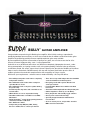
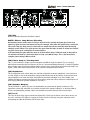
BULLY™ GUITAR AMPLIFIER
Congratulations on purchasing this Budda guitar amplifier. After initially creating a reputation for
producing boutique tone machines, we have now raised the bar for modern multi-channel tube guitar
amplifiers by producing possibly the most sophisticated tube guitar amp available.
By not compromising on the construction or quality of any parts, we can also ensure that for all its
features, the most important thing - tone - is not compromised.
And what an array of different tones there are! With three completely independent channels, a tubedriven preamp boost, real spring reverb as well as the patent pending ‘PowerPan’ tube to solid state
rectification control, this amp is a tone chaser’s dream. Not only that, but with the flexibility of the effects
loops as well as footswitch and MIDI control, this amp will also prove itself to be up to the tasks of
modern guitarists who need their amp head to be the centerpiece of a larger system.
Whichever your requirements - authentic tone or modern flexibility - this amp will deliver.
t'JWF"9QSFBNQUVCFTVTFEJOUISFFDPNQMFUFMZ
JOEFQFOEFOUDIBOOFMT
t0OF"9UVCFVTFEJOUVCFESJWFOTUPNQCPY
TUZMF0WFS#PPTUDJSDVJU
t0OF"9UVCFVTFEBTUIFQIBTFTQMJUUFSESJWJOH
UIFQPXFSBNQ
t'PVS&-QPXFSBNQUVCFTBOEDPOWFSUJCMFUPVTF
GPVS-UVCFT
t-&%JOEJDBUJPOPGDPSSFDUPVUQVUUVCFCJBTJOH
t5XP6SFDUJmFSUVCFTDPOWFSUJCMFUPVTF"3
(;UVCFT
t6OJRVF1PXFS1BO™DPOUSPMBMMPXTQBOOJOHCFUXFFO
TPMJETUBUFBOEUVCFSFDUJmDBUJPO
t'VMM)BMG1PXFSTXJUDI
t*OEFQFOEFOUQSFBNQ&2#BTT.JE5SFCMF
1SFTFODFBOE3FTPOBODFDPOUSPMTQFSDIBOOFM
t5ISFFFGGFDUTMPPQTXJUIJOEFQFOEFOU4FOEBOE.JY
DPOUSPMTBOE$IBOOFMPS(MPCBMPQUJPOT
t3FBMTQSJOHSFWFSCXJUITFQBSBUF3FWFSCMFWFM
DPOUSPMQFSDIBOOFM
t'PPUTXJUDIBCMF.BTUFS#PPTUXJUIVTFSEFmOFE
CPPTUMFWFM
t4MBWF0VUBOE1SFBNQ0VU1PXFS"NQ*OMJOLKBDLT
t$BCJOFUJNQFEBODFTXJUDIPS0INT
t)FBWZEVUZ1PXFSBOE4UBOECZUPHHMFTXJUDIFT
t$MBTTJDQPXFSTUBUVTJOEJDBUPSMBNQ
t4QFDJBMMZEFTJHOFECVUUPONVMUJGVODUJPO
GPPUDPOUSPMMFS
t4UPSFTDVTUPNQSFTFUTBOEQSPWJEFTFYUFOTJWF
.*%*DPOUSPMGPSBVUPNBUJPO
QUICK GUIDE
Please at least read this section before using your new amplifier. We then recommend reading the rest of the manual
so you can get the most out of this very sophisticated unit.
Before applying power:
1) When setting up, ensure that the amplifier speaker output is connected to your speaker enclosure with a good
quality speaker cable (do not use a normal shielded instrument cable) and that the Impedance switch on the rear
panel is set to the correct setting. The impedance of your enclosure will be marked on the back: 4, 8 or 16 Ohm. If
you are using two enclosures of equal impedance rating connected together or connected separately back to the
amplifier, then set the impedance switch to the setting that is half the individual value . Therefore, if using two 8 Ohm
enclosures, then set the switch to 4 Ohm.
2) Before connecting the supplied IEC line cord make sure the Power and Standby switches are in their down
(off) position.
3) Connect the footcontroller with the supplied 8 pin DIN cable to FOOT/IN on the rear of the amp, and connect
your guitar to the HIGH Input with a good quality shielded instrument cable.
FRONT PANEL FUNCTIONS: WHAT THEY DO AND HOW TO USE THEM
(1) High Gain
(2) Medium Gain
Use ¼” jacks for connecting to your guitar, or to the output of the last effects pedal if any are used before
the amp.
)JHI is high impedance and high sensitivity. This will be the most common input to use. This puts the full
level of your guitar into the channels, therefore allowing the highest gain.
.FEJVNis medium impedance and medium sensitivity. This can be used if less gain is required if using
an active guitar (battery powered) or if the guitar signal has already been boosted by an external device.
It features an attenuator that reduces the input signal by ~10dB.
Preamp Channels
There are three completely independent all-tube preamp channels. Keeping them completely
independent means that we did not have to compromise the tone on any channel for the sake of another.
Although initially the array of the numerous controls may seem intimidating, these are actually arranged
identically for each channel. Therefore you will soon get used to which control to go to for adjusting a
particular part of the sound on that channel.
Apart from separate eq, reverb, presence and resonance controls, each channel also features an ‘OverBoost’ control. The Over-Boost circuit is a footswitchable tube-driven stomp box style gain boost applied
before each preamp stage.
BULLY™ GUITAR AMPLIFIER
4) Before switching on, set the Master Volume to the minimum setting. The first time the amp is used, we
recommend setting all the other controls to their mid setting.
5) Now flip the Power switch to the up (on) position. The power status lamp should be lit. Wait at least one minute
for the tubes to warm up. 'BJMVSFUPEPUIJTDBOEBNBHFUIFUVCFTBOESFEVDFUIFJSMJGF You can use this time to
adjust the controls as mentioned above.
6)After at least one minute you can flip the Standby switch to the up (on) position. You will notice that the amp
defaults to Preset 1. Gradually turn up the Master Volume to the required playing level. Now you can adjust the rest
of the controls to taste, change channels and operate the other functions on the front panel and footcontroller.
7) During short periods of not playing the amplifier can be switched to Standby so that it isn’t producing any output,
but is warmed up for immediate use when needed. If longer than 30 minutes or so it’s probably best to switch off
completely.
8)At the end of a playing session it’s good practice to turn the Master Volume to minimum then flip the Standby
switch to the down (off) position before switching the Power switch to the down (off) position. The rest of the
controls can be left as set. Finally we recommend not moving the amplifier for a few minutes to allow the tubes time
to cool down.
Channel 1
This is the ‘clean’ channel. Depending on the specific setting of the controls, it can produce sparkly clean
sounds with plenty of headroom, through to warmer clean tones with a bit of edge from the tubes when
driven harder.
(3) Channel Select:
Press this switch to select Channel 1, the corresponding LED will be lit either green or red.
Green is the normal setting; red is when Over-Boost is also on for this channel. Pressing this switch again
will alternate between with or without Over-Boost.
If Over-Boost is selected for this channel then this is remembered when you change to another channel.
Therefore you don’t need to switch it on each time you return to this channel.
Switching of both the channel and Over-Boost can also be done on the footcontroller.
(4) Over-Boost:
If Over-Boost is selected on this channel then this control becomes active and sets the amount of pre
gain/drive for this channel. At the minimum setting there will be little difference between the normal
and Over-Boost sounds, but, as the control is increased, the tube driven stomp box style overdrive will
increase and be blended with the straight sound. Blending the two sounds helps to keep the tone well
defined as it retains the attack of the original notes.
FRONT PANEL FUNCTIONS: WHAT THEY DO AND HOW TO USE THEM
(5) Gain
This control sets how much signal is sent through the Channel 1 preamp. Low to medium settings will
produce clean sounds. As the control is turned further clockwise the tone will get warmer and eventually
start to add a small amount of overdrive.
(6) Treble
This passive control sets the level of the high frequencies for Channel 1.
This will seem more powerful when Over-Boost is switched on due to more high frequencies being
present in the distortion.
(7) Mid
This passive control sets the level of the mid range frequencies for Channel 1.
Again it will be more powerful when Over-Boost is switched on.
(8) Bass
This passive control sets the level of the low frequencies for Channel 1.
(9) Volume
This sets the overall level of Channel 1 and is used to balance the sound with the other channels after the
Gain has been set.
(10) Reverb
This sets the level of the spring reverb effect on Channel 1.
This is also switchable using the footcontroller.
(11) Presence
This is used to fine tune the high frequency range of the speaker enclosure while on Channel 1, by
varying the damping factor of the tube power stage at high frequencies.
(12) Resonance
This is used to fine tune the low frequency range of the speaker enclosure while on Channel 1, by varying
the damping factor of the tube power stage at low frequencies.
BULLY™ GUITAR AMPLIFIER
Channel 2
This is the ‘crunch’ channel. Depending on the specific setting of the controls it can produce lightly
overdriven tones that clean up nicely when the guitar volume is turned down, through to quite heavily
overdriven tones at high Gain settings, especially with the Over-Boost switched on.
(13) Channel Select
Works the same as on Channel 1 but for Channel 2, including switching on Over-Boost.
Can also be switched on the footcontroller.
(14) Over-Boost
Works the same as on Channel 1 but for Channel 2.
(15) Gain
Works the same as on Channel 1 but for Channel 2, however, as more gain is available, it will have a more
radical effect to your tone, producing more overdrive the further clockwise it is turned.
(16) Treble
This passive control sets the level of the high frequencies for Channel 2.
(17) Mid
This passive control sets the level of the mid range frequencies for Channel 2.
(18) Bass
This passive control sets the level of the low frequencies for Channel 2.
(19) Volume
Works the same as on Channel 1 but for Channel 2.
(20) Reverb
Works the same as on Channel 1 but for Channel 2.
(21) Presence
Works the same as on Channel 1 but for Channel 2.
(22) Resonance
Works the same as on Channel 1 but for Channel 2.
FRONT PANEL FUNCTIONS: WHAT THEY DO AND HOW TO USE THEM
Channel 3
This is the ‘high gain’ channel. Depending on the specific setting of the controls, it can produce warm
overdriven tones, seriously heavy thrash tones and anything in-between.
(23) Channel Select
Works the same as on Channel 1 but for Channel 3, including switching on Over-Boost. Can also be
switched on the footcontroller.
(24) Over-Boost
If Over-Boost is selected then this control becomes active. On Channel 3 this acts like a tube-driven,
mid-focused, clean boost before the main preamp stage. As the signal then goes into a high gain
preamp, this will help to overdrive this channel further, giving even more saturation and sustain that’s
great for certain ‘shredding’ guitar techniques such as tapping, legato, and sweep picking. Maximum
boost is ~20dB.
(25) Gain
Works the same as on Channel 1 but for Channel 3 however, as more gain is available, it will have a more
radical effect to your tone, producing more overdrive the further clockwise it is turned.
(26) Treble
This passive control sets the level of the high frequencies for Channel 3.
(27) Mid
This passive control sets the level of the mid range frequencies for Channel 3.
(28) Bass
This passive control sets the level of the low frequencies for Channel 3.
(29) Volume
Works the same as on Channel 1 but for Channel 3.
(30) Reverb
Works the same as on Channel 1 but for Channel 3.
(31) Presence
Works the same as on Channel 1 but for Channel 3.
(32) Resonance
Works the same as on Channel 1 but for Channel 3.
BULLY™ GUITAR AMPLIFIER
MASTER SECTION
(33) Boost
This sets a user definable volume boost that can be applied to any of the three channels and can be
turned on and off using the footcontroller. This is extremely useful when you need a boost in volume for
solos, as you don’t have to dedicate a particular channel for that use.
The control has been calibrated so that the mid point setting gives a +6dB boost and on full gives +10dB.
(34) Volume
This sets the overall level of the amp. Once the desired balance between the three channels has been
set using their own Volume controls, the entire level of the unit can be increased or decreased by
adjusting this control. A good policy to avoid unwanted and possibly damaging loud sounds is to turn
this control to minimum before turning the unit on. However it can be left set to the required stage
volume and Standby switched to “Off” during breaks, therefore ensuring the correct volume level
when returning to the stage.
(35) Power Switch
This two-way toggle switch applies mains power to the unit. Down is off, up is on.
Before switching on, check that the Standby is in the “Off” position.
(36) Power Status Lamp
This indicator illuminates when mains power is being applied to the amp.
(37) Standby Switch
This two-way toggle switch allows the amp to be placed in Standby mode, where the amp can warm up
or remain warmed up, before switching up to the fully active mode. Down is Standby, up is fully on.
*NQPSUBOU Always have this set to Standby when first switching on the Power switch. Then allow the
amp to warm up for at least one minute before switching out of Standby.
Also, at the end of use, try to switch this off at least a few seconds before turning the Power switch off.
This prevents any unwanted noise.
REAR PANEL
(38) MIDI In/Footswitch
This 8-pin DIN connector is provided for the connection of the remote footcontroller. Preferably this
should be connected before the amp is powered up. See the FOOTCONTROLLER section of this manual
for a more detailed explanation of operation.
This can also be used as a MIDI IN connection, using a standard 5-pin MIDI cable, if the amp is going to
be controlled by a separate MIDI controller other than the supplied footcontroller. See the MIDI section of
this manual for a more detailed explanation of the MIDI features.
(39) MIDI Out
This 5-pin DIN connector is provided to send MIDI messages, including Program Change and Continuous
Controller messages, to external MIDI devices. It is useful for linking two amps and keeping their
functions synchronized, and for sending your custom preset data to another amp or MIDI backup device.
It’s also useful to control presets on effect units you may have in the effects loops. See the MIDI section
of this manual for a more detailed explanation of the MIDI features.
Effects Loop 1
This is the dedicated effects loop for Channel 1. It will only be available for use when Channel 1 is
selected. It can be switched on and off using the footcontroller.
(40) Level
This control sets the level of Channel 1 signal being sent to external effects and/or signal processors
from the Send jack (41) underneath. The control is calibrated so that, with most effects, the mid point
setting will produce basically the same level when switching the loop on or off. However, it will give
approximately a +/-10dB variation in either direction if required to achieve the desired balance with the
loop on or off.
(41) Send
This ¼” mono (TS) jack is to connect to the input of an external effect or signal processor.
It will only send signal if Channel 1 and Effects Loop 1 are selected.
Use shielded cable with ¼” mono (TS) phone plugs for all effects loop connections.
(42) Return
This ¼” mono (TS) jack is to connect to the output of an external effect or signal processor.
(43) Mix
The precise function of this control is dependant on the setting of the Global switch (49).
If Global is set to Series then this control sets the mix between the normal (dry) sound of Channel 1 and
the sound of the effect being used in Effects Loop 1. Fully counter-clockwise will be just the normal dry
sound (no effects); turning clockwise will increase the amount of the effect heard until fully clockwise
where only the sound from the effect/processor is heard.
BULLY™ GUITAR AMPLIFIER
To use as a series loop, turn this control fully clockwise. To use it as a normal parallel loop set it at or near
the mid point to give the required balance between dry and effect.
If Global is set to Parallel, the normal (dry) signal bypasses the effects loops and is always present. In this
mode the Mix control sets the level of the effect being used in Effects Loop 1 that is blended with the dry
signal. Turning the Mix control clockwise increases the level of the effect.
Effects Loop 2
Depending on the setting of the Master / Channel switch (44) this can either be the dedicated effects loop
for Channel 2 or an effects loop for all three channels.
It can be switched on and off using the footcontroller.
(44) Master / Channel
When this switch is set to Channel, Effects Loop 2 will be dedicated for use on Channel 2 only. Effects
Loop 2 will then only be available for use when Channel 2 is selected, and this will work the same way as
Effects Loops 1 and 3 work with Channels 1 and 3.
This setting can be used if different effects and/or signal processors are to be used for each channel.
Setting this switch to Master will enable Effects Loop 2 to be used as a master effects loop on all three
channels. For fairly simple set-ups, with few effects or one multi-processor, this will be the most usable
setting.
However, as this is now a Master effects loop, the signal is routed so that if any effects are used in Effects
Loop 1 or 3, they can still be used on Channels 1 and 3 respectively and will be placed in series before
Effects Loop 2.
In this mode, the footcontroller can still be used to turn the individual Effects Loops on and off, with
Effects Loop 2 available on all three channels and Loops 1 and 3 still dedicated to Channels 1 and 3.
(45) Level
This control sets the level of signal being sent to external effects and/or signal processors from the Send
jack (46). It is calibrated the same as Level (40) above.
If Channel mode is selected, this will be the level of Channel 2.
If Master mode is selected, it will be the level of whichever channel is on, as well as the level of any
effects that are being used in Effects Loop 1 or 3.
(46) Send
Similar to Send (41) above but for Effects Loop 2.
It will only send signal if this loop is turned on either with Channel 2 or in Master mode.
(47) Return
Similar to Return (42) above but for Effects Loop 2.
(48) Mix
Similar to Mix (43) above but for Effects Loop 2.
If Channel mode is selected, this will control the mix of the effect on Channel 2.
If Master mode is selected it will control the mix of the effect on the overall sound, regardless of the
channel selected.
(49) Global – Parallel/Series
This determines the routing of the signal around the effects loops.
In Parallel setting, the normal (dry) signal (from whichever channel is being used) is effectively ‘hard
wired’ to go directly around the effects loops unaltered. Therefore, any effects that are applied are always
in parallel with the dry signal, which ensures tonal integrity.
In Series mode, the direct signal path is turned off and the whole signal is passed to the effects loop
circuitry. Therefore, the user has complete control over the mix of dry and effects signals for each
channel by using the controls as described above. Due to the design and very high quality of the parts
used, the effects loop circuitry will be sonically transparent.
1MFBTFOPUF5IFFGGFDUPGUIJTTXJUDIPOMZBQQMJFTXIFOBUMFBTUPOFPGUIFFGGFDUTMPPQTBSFCFJOH
VTFE*GUIFZBSFPGGUIFESZTJHOBMBMXBZTCZQBTTFTUIFFGGFDUTMPPQDJSDVJUSZ
Effects Loop 3
This is the dedicated effects loop for Channel 3. It will only be available for use when Channel 3 is
selected. It can be switched on and off using the footcontroller.
(50) Level
This control sets the level of Channel 3 signal being sent to external effects and/or signal processors from
the Send jack (51). It is calibrated the same as Level (40) above.
(51) Send
Similar to Send (41) above but for Effects Loop 3.
It will only send signal if Channel 3 and Effects Loop 3 are selected.
(52) Return
Similar to Return (42) above but for Effects Loop 3.
BULLY™ GUITAR AMPLIFIER
(53) Mix
Similar to Mix (43) above but for Effects Loop 3.
NOTE: Effects Loop Return Circuitry
"OJNQPSUBOUGFBUVSFPGUIFSFUVSODJSDVJUSZJTUIBUJUJODMVEFTTQFDJBMMZEFTJHOFEHBUFDJSDVJUTUIBU
BMMPXBOZTJHOBMQSFTFOUBUUIF3FUVSOKBDLUPQBTTUISPVHIFWFOXIFOUIFTQFDJmDMPPQJTUVSOFEPGG
5IJTNFBOTUIBUBOZEFMBZFDIP
PSSFWFSCUBJMTBSFBMMPXFEUPGBEFPVUOBUVSBMMZSBUIFSUIBOCFJOH
BCSVQUMZDVUPGG*GUIFSFJTOPTJHOBMQSFTFOUUIFHBUFTBMMPXUIFMPPQTUPXPSLBTOPSNBMBOETIVUPGG
BOZOPJTFUIBUNBZCFDPNJOHGSPNBOFYUFSOBMEFWJDF
*O$IBOOFMNPEFUIFHBUFTXPSLUIFTBNFPOBMMUISFFFGGFDUTMPPQT*O.BTUFSNPEFJGEFMBZFGGFDUT
BSFOFFEFEBUBMMUJNFTJUJTCFTUUPQVUUIFNJO-PPQUIF.BTUFS-PPQ5IJTJTEVFUPUIFNPSF
DPNQMFYTJHOBMSPVUJOHJO.BTUFSNPEF
(54) Power Amp In / PreAmp Out
This ¼” jack facilitates a simple way to link together two BULLY amps if required. This is a passive,
bidirectional connection that just requires the use of a standard shielded cable with ¼” mono (TS) phone
plugs. Simply connect from one amp to another and the same signal will be heard from both amps. The
signal is taken from and/or injected after all the controls except the Master Volume.
(55) Impedance
This three-position slide switch allows the selection of speaker enclosure impedance. If one enclosure
is used, simply set this to the impedance rating marked on the back of the cabinet. If two enclosures of
equal impedance are used, the switch should be set to half the individual value. For example, two
16 Ohm enclosures would necessitate an 8 Ohm setting, while two 8 Ohm enclosures would require a 4
Ohm setting. Minimum speaker impedance is 4 Ohms.
(56) Speaker Outputs
These paralleled ¼” mono (TS) jacks are provided for the connection of speaker enclosures. The
Impedance switch (55) should be set to match the load of the speaker cabinet(s), as described above.
Always use good quality speaker cables (not shielded instrument cable) for these connections.
(57) Level
This sets the level of the signal at the Slave output (58). If slaving to an effects unit or other device, use
the unit’s sensitivity LED lights as a gauge to set the slave level, thereby using this control to avoid
overloading the input of the effects unit or slave amp.
(58) Slave Out
This ¼” mono (TS) jack is a passively buffered signal that is in parallel with the speaker output. It contains
the full complement of preamp and power amp characteristics of the amp. Use this output to send the
signal to a power amplifier connected to additional speaker cabinets for a louder version of the amp.
(59) Power Level
This switch sets the maximum power level to either Full or Half (setting it to half literally shuts off two of the
four power output tubes). It also switches off one of the two rectifier tubes to more authentically sound like
a vintage 50 watt guitar amp. Therefore, if the rectifier tubes are being used, both the ‘power amplification’
stage and the ‘power supply rectification’ are being halved. The actual maximum power levels will be
dependant on the actual power tubes used and the PowerPan™ setting (more on this below).
When the unit is in HALF-POWER mode, the IMPEDANCE SELECTOR can be more accurately matched
to the cabinet according to the impedance selector markings under this switch. In HALF-POWER mode,
the nominal load that the amp would be optimized for in full-power mode would double in impedance. If
you are using an 8 Ohm cabinet in full-power mode and you switch to half-power mode, maximum “halfpower” would be obtained through the 8 Ohm cabinet on the full-power 16 Ohm setting.
(60) PowerPan™
This is a patent pending feature that enables the user to select Tube rectification, Solid State rectification,
or a blend of anywhere in-between. This allows the user to take advantage of the different compression
effects that happen at transients and high volume, which are caused by the variation in power supply sag
with tube or solid state rectification. It goes further than what has been done before by allowing the user
to blend between the two.
Used in combination with the Power Level switch, the PowerPan feature allows many different power amp
tones at different volume levels.
For example: 4x 6L6GC with 2x 5U4 will produce ~100W at full power with solid state rectification and go
down to about 25W at half power with just tube rectification.
Using 4x EL34 will generally produce slightly more power (maximum ~120W with solid state rectification)
and using 5AR4/GZ34 rectifier tubes will reduce the power supply sag effects, therefore also generally
having slightly more power headroom.
BULLY™ GUITAR AMPLIFIER
(61) HT Fuse
This fuse is for the high voltage supply for the tubes. Sometimes when a tube goes faulty it will result in
this fuse blowing. A fuse is included because without it, collateral damage could occur that could be even
more inconveniencing. The fuse is located within the cap of the fuse holder. This fuse must be replaced
with one of the same type and value to avoid damaging the amplifier and voiding the warranty. If the amp
repeatedly blows the fuse, it should be taken to a qualified service center for repair.
8"3/*/(5)&'64&4)06-%0/-:#&3&1-"$&%"'5&35)&108&3$03%)"4#&&/
%*4$0//&$5&%
(62) IEC Mains Connector
This is a standard IEC power connector. An AC power cable having the appropriate AC plug and ratings
for the intended operating voltage is included in the carton. The Power Cable should be connected to the
amplifier before connecting to a suitable AC outlet.
U.S. Domestic AC Power Cable
5IFQPXFSDBCMFTVQQMJFEXJUIUIFVOJUJTBIFBWZEVUZUISFFDPOOFDUPSUZQFXJUIBDPOWFOUJPOBM
7"$QMVHXJUIHSPVOEQJO*GUIFPVUMFUVTFEEPFTOPUIBWFBHSPVOEQJOBTVJUBCMFHSPVOEJOHBEBQUFS
TIPVMECFVTFEBOEUIFUIJSEXJSFTIPVMECFQSPQFSMZHSPVOEFE
/FWFSCSFBLPGGUIFHSPVOEQJOPOBOZFRVJQNFOU*UJTQSPWJEFEGPSZPVSTBGFUZ
NOTE FOR UK ONLY:
*GUIFDPMPVSTPGUIFXJSFTJOUIFNBJOTMFBEPGUIJTVOJUEPOPUDPSSFTQPOEXJUIUIFDPMPVSFENBSLJOHT
JEFOUJGZJOHUIFUFSNJOBMTJOZPVSQMVHQSPDFFEBTGPMMPXT
5IFXJSFUIBUJTDPMPVSFEHSFFOBOE
ZFMMPXNVTUCFDPOOFDUFEUPUIFUFSNJOBMUIBUJTNBSLFECZUIFMFUUFS&UIFFBSUITZNCPMPSDPMPVSFE
HSFFOPSHSFFOBOEZFMMPX
5IFXJSFUIBUJTDPMPVSFECMVFNVTUCFDPOOFDUFEUPUIFUFSNJOBMUIBUJT
NBSLFEXJUIUIFMFUUFS/PSUIFDPMPVSCMBDL
5IFXJSFUIBUJTDPMPVSFECSPXONVTUCFDPOOFDUFEUP
UIFUFSNJOBMUIBUJTNBSLFEXJUIUIFMFUUFS-PSUIFDPMPVSSFE
(63) Mains Fuse
This fuse is for the mains supply for the amp. The fuse is located within the cap of the fuse holder. This fuse
must be replaced with one of the same type and value to avoid damaging the amplifier and voiding the
warranty. If the amp repeatedly blows the fuse, it should be taken to a qualified service center for repair.
8"3/*/(5)&'64&4)06-%0/-:#&3&1-"$&%"'5&35)&108&3$03%)"4#&&/
%*4$0//&$5&%
TOP PANEL
(64 - 70) ECC83 / 12AX7 / 7025 x7
Tubes for Over-Boost, Ch 1, Ch 2 , Ch 2, Ch 3, Ch 3, Phase Splitter respectively.
When replacing please use good quality tubes.
(71 – 74) EL34/6L6 x4 Power Tubes
Apart from EL34 type, other types can be used including 6L6, 6550, KT66, KT88 and 6CA7.
When replacing please use matched quartets of good quality tubes and ensure the biasing is set correctly
as described below.
(75) 5U4 / 5AR4 / GZ34 x2 Rectifier Tubes
Apart from 5U4 type, either or both of these can be replaced with 5AR4 / GZ34 type.
We have found the 5U4 type makes the tonal difference of tube rectification more apparent.
When replacing please use good quality tubes.
/05&%VFUPUIFIJHIUFNQFSBUVSFTEPOPUBUUFNQUUPSFQMBDFBOZUVCFTVOMFTTUIFBNQMJmFSIBT
CFFOUVSOFEPGGGPSBUMFBTUNJOVUFT5IJTTIPVMEPOMZCFDBSSJFEPVUCZBUFDIOJDBMMZDPNQFUFOU
QFSTPO
(76) Reverb Connections
These connect to the spring reverb device.
(77) Bias Status
These three LEDs indicate the power tube bias current.
Red is Hot (too high), Green is Normal and Blue is Cold (too low).
These should be observed when checking or adjusting the bias as described below.
It is normal for the red LED to flash on during actual use at medium to high volumes.
(78) Bias Adjust
This hole allows access to the trim control inside. Adjusting this will vary the bias supply. This should
only be adjusted if it is fully understood what this does, otherwise it could damage your tone, or worse,
damage your power tubes.
BULLY™ GUITAR AMPLIFIER
CHECKING AND ADJUSTING THE BIAS IS EXTREMELY EASY TO DO BY FOLLOWING
THIS PROCEDURE:
8"3/*/(3FNPWJOHUIFSFBSQBOFMXJMMFYQPTFUIFUVCFT5IFTFBSF7&3:IPUBOEUPVDIJOHUIFN
TIPVMECFBWPJEFE5IJTQSPDFEVSFTIPVMEPOMZCFDBSSJFEPVUCZUFDIOJDBMMZDPNQFUFOUQFPQMFBOEBU
UIFJSPXOSJTL
t&OTVSF1PXFSBOE4UBOECZTXJUDIFTBSFJOUIFEPXOPGG
QPTJUJPO3FNPWFSFBSQBOFM
t$POOFDUBNQUPTQFBLFSPSEVNNZMPBE
BOEQPXFSTVQQMZ
t5VSO.BTUFS7PMVNFUPNJOJNVNBOEUVSO1PXFSTXJUDIPO
t"UUIJTQPJOUPOMZUIFCMVF-&%TIPVMECFPO
t0OSFBSQBOFMTFUUIF1PXFS-FWFMTXJUDIUP'VMMBOE1PXFS1BOUPGVMMZ4PMJE4UBUF
t"MMPXBNQUPXBSNVQGPSBGFXNJOVUFT
t5VSOGSPN4UBOECZUPGVMMZPOBOEPCTFSWFUIF#JBT4UBUVT-&%T
t*GUIFHSFFO-&%JTMJUUIFOUIF#JBT"EKVTUJTTFUDPSSFDUMZBOEDBOCFMFGUBMPOF
t*GUIFSFE-&%JTMJUUIFOUIFCJBTJTUPPIJHIJGCMVF-&%JTMJUUIFCJBTJTUPPMPX
t5PBEKVTUDBSFGVMMZJOTFSUBUSJNNFSUPPMJOUPUIF#JBT"EKVTUIPMFBOEMPDBUFUIFDPOUSPMJOTJEF
XIJMFCFJOHWFSZDBSFGVMUPOPUUPVDIUIFUVCFT0ODFJOQPTJUJPOUVSODPVOUFSDMPDLXJTFUPMPXFS
CJBTDMPDLXJTFUPJODSFBTFUIFCJBT5IFPQUJNBMTFUUJOHJTHSFFOKVTUCFGPSFUIFSFEDPNFTPO
t0ODFJUJTTFUUVSOPGGBNQBOEJNNFEJBUFMZSFQMBDFUIFSFBSQBOFM
FOOTSWITCH
(79) Remote Cable
This eight-pin DIN connector is provided for connecting the footcontroller to the amplifier IN/FOOT (38) via the cable included in
the carton. Preferably connections at the footcontroller and the amplifier should be made before the amp is powered up.
(80) Preset Mode
This switches the footcontroller between NORMAL mode (default, LED off) and PRESET mode (LED red).
Quick Boost Feature: As described below, when in preset mode, the 1-9 switches will recall your 9 custom presets.
When you press the switch of the preset that is already active, it will toggle the status of the Master Boost. This allows a quick
way to recall a preset for a solo and get it boosted very quickly (just hit the switch twice!). Otherwise, you’d have to hit it, then
toggle out of preset mode, then hit the Master Boost switch – tap dance! (Of course, you can save the preset with the boost
active, and then the 2nd press would disable the boost.) To make the Master Boost status visual while in preset mode (red LEDs
for mode/preset) the 9/Master Boost LED will blink green when the boost is enabled. (If on preset 9, the color will toggle between
red and green to show preset number and Master Boost on.)
(81) Effects Loop 1 / Preset # 1
NORMAL mode: This turns on Effects Loop 1 when using Channel 1. If selected, the LED will be lit green even if on a different
channel. Also it can be switched on and off even when using another channel. However, Loop 1 will only actually be on when
using Channel 1.
PRESET mode: This selects Preset 1. If selected, the LED will be lit red.
(82) Effects Loop 2 / Preset # 2
NORMAL mode: This turns on Effects Loop 2 when using Channel 2, and also when using Channels 1 and 3 if Loop 2 is set to
Global (refer to point 44). If selected, the LED will be lit green even if on a different channel. Also it can be switched on and off
even when using another channel.
PRESET mode: This selects Preset 2. If selected, the LED will be red.
(83) Effects Loop 3 / Preset # 3
NORMAL mode: This turns on Effects Loop 3 when using Channel 3. If selected, the LED will be lit green and it can be switched
on and off even when using another channel. However, Loop 3 will only actually be on when using Channel 3.
PRESET mode: This selects Preset 3. If selected, the LED will be red.
BULLY™ GUITAR AMPLIFIER
(84) Reverb / Preset #4
NORMAL mode: This turns the REVERB on and off. The LED will be lit GREEN.
PRESET mode: This selects Preset 4. If selected, the LED will be red.
(85) Over Boost / Preset #5
NORMAL mode: This turns OVER BOOST on and off for the current channel. When switching between channels, this will
remember what the last setting was for each. The LED will be green when OVER BOOST is on.
PRESET mode: This selects Preset 5. If selected, the LED will be red.
(86) Channel Select 1 / Preset #6
NORMAL mode: This selects Channel 1. The LED will be lit GREEN. If pressed a 2nd time, the channel will return to the previous
setting. This allows quick changing between two channels using a single switch.
PRESET mode: This selects Preset 6. If selected, the LED will be red.
(87) Channel Select 2 / Preset #7
NORMAL mode: This selects Channel 2. The LED will be lit GREEN. If pressed a 2nd time, the channel will return to the previous
setting. This allows quick changing between two channels using a single switch.
PRESET mode: This selects Preset 7. If selected, the LED will be red.
(88) Channel Select 3 / Preset #8
NORMAL mode: This selects Channel 3. The LED will be lit GREEN. If pressed a 2nd time, the channel will return to the previous
setting. This allows quick changing between two channels using a single switch.
PRESET mode: This selects Preset 8. If selected, the LED will be red.
(89) Master Boost / Preset #9
NORMAL mode: This turns the Master Boost on and off. The LED will be lit green.
PRESET mode: This selects Preset 9. If selected, the LED will be red.
Using Preset Mode
Each of the 9 presets remembers the current channel, over-boost on/off, reverb on/off, effects loop on/off and master boost
on/off. Additionally, it remembers the over-boost and effects loop status of the two inactive channels. This way you can, for
example, have a clean preset saved without over-boost, and know that when you switch to Channel 2, over-boost will be on.
The amp comes from the factory with 9 default presets that you can modify at will. When the PRESET MODE light is on, you can
use the 9 other footswitches to recall those 9 presets. At any time you can switch to NORMAL mode and make changes to that
sound. This can be during a performance and not permanently stored, or to edit a preset and store to one of the 9 settings.
/05&5IFBNQXJMMQPXFSVQJOUP1SFTFU*GUIFBNQJTQPXFSFEVQXJUIPVUUIFGPPUTXJUDIDPOOFDUFEUIFFGGFDUTMPPQT
SFWFSCBOENBTUFSCPPTUXJMMCFFOBCMFE5IJTJTCFDBVTFUIFSFJTOUBXBZUPFOBCMFUIFNNBOVBMMZXJUIPVUUIFGPPUTXJUDI
Storing Presets
To store the current settings into one of the 9 presets, you start by holding the PRESET MODE switch down for a second or two,
after which the other LEDs will blink (except the one for the current preset which will be on steady – a way to remind you of
which preset you were working with). At this point you can press one of the 9 preset switches to store there, or press PRESET
MODE again to cancel.
You can initiate this from PRESET mode or from NORMAL mode. After the store (or cancel) it will return to the mode you were
in. So you can setup and store 9 presets without ever entering PRESET mode if you wish. It’s typical to set up your sound in
NORMAL mode, then store your creation to one of the presets.
Linking to another amp and/or effects units with the MIDI Out
You can connect the MIDI Out to the MIDI In of another BULLY to synchronize the two amps. With the footswitch connected to
the first amp, any changes you make with the footswitch (or front panel) will be duplicated on the 2nd amp – if the 2nd amp is on
the same MIDI channel.
You can also link the MIDI from the amp (or from the 2nd amp) to an effects unit to synchronize presets. If the effects unit can
store presets, they can change automatically when you recall presets on the footswitch.
POWER AMPLIFIER SECTION
56#&4
Four EL34 tubes with 12AX7 phase splitter / driver
3"5&%108&3065165*.1&%"/$&
120 Watts RMS into 16, 8 or 6 Ohms
108&3!$-*11*/(
(typically @ 5% THD, 1 kHz, 120 VAC line)
100 Watts RMS into 16, 8 or 4 Ohms
'3&26&/$:3&410/4&
+/-3 dB, 50Hz to 20kHz @ 90 Watts RMS into 8 Ohms
)6./0*4&
Greater than 76dB below rated power
108&3$0/46.15*0/
Domestic: 400 Watts, 50/60 Hz, 120 V AC
Export: 400 Watts, 50/60Hz, 220-230/240 V AC
PREAMP SECTION:
56#&4
Six 12AX7 tubes
5)&'0--08*/(41&$4"3&.&"463&%!,);
8*5)5)&$0/530-413&4&5"4'0--084
Over-Boost off
All EQ controls mid way
Channel Volumes @ maximum
Master Volume @ half way
Boost on and @ maximum
Resonance and Presence control @ mid way
Effects loops off
Nominal levels are with Gain @ mid way
All levels increased by 10dB if using Medium input.
$)"//&-
Nominal input level: -12dBu, 200mV RMS
$)"//&-
Nominal input level: -46dBu, 4mV RMS
$)"//&-
Nominal input level: -58dBu, 1mV RMS
&''&$544&/%
Load impedance: 1k Ohms or greater
Minimum Output: -32dBu, 0.02mV RMS (with –20dBu
signal)
Maximum Output: +1dBu, 1.6V RMS (with 0dBu signal)
Unity gain with Send set at mid position, -10dB at min,
+4dB at max.
&''&$543&563/
Impedance: 100k Ohms
Minimum Input Sensitivity: -12dBu, 0.18mV RMS
Maximum Input Sensitivity: +10dBu, 2.5V RMS
108&3".106513&".1*/
Nominal output level: +4dBu, 1.2V RMS
Load impedance: 1k Ohms or greater
Minimum Input Sensitivity: 0dBu, 0.775V RMS (with
Master on max)
Maximum Input Sensitivity: +6dBu, 1.6V RMS (with
Master on half)
Input impedance: 250k Ohms
4-"7&065
Maximum output level: +22dBu, 10V RMS (at full
power)
Load impedance: 10k Ohms or greater
REMOTE FOOTCONTROLLER:
Special ten-button metal footswitch with LED indicators
and detachable cord (supplied). Selects between three
channels, Over-Boost, three effect loops, Reverb, and
Master Boost as well as nine Preset modes.
4:45&.)6./0*4&!/0.*/"--&7&-
(Clean channel – 20Hz to 20kHz unweighted)
Greater than 74dB below rated power
&26"-*;"5*0/
Specifically designed bass, mid & treble passive-type EQ
on each preamp channel.
Resonance and Presence damping EQ on each channel.
%*.&/4*0/48&*()5
11.5” (292mm) H x 28.25” (717mm) W x 11.25” (286mm) D
60.6 lbs (27.55 kg)
/05&'031301&37&/5*-"5*0/"--08w
..
'30./&"3&45$0.#645*#-&463'"$&
BULLY™ GUITAR AMPLIFIER
Budda BULLY™ MIDI Implementation
This amp is designed to be extremely functional with the included 10-button footswitch. The 8-pin footswitch jack also works as a standard
5-pin MIDI input - to go along with the standard 5-pin MIDI output. There are times when the amp will be run with other types of MIDI foot
controllers, a PC in the studio, or by an automated rack rig - or linked to another BULLY via MIDI. This is the information you need to mate
this amp with other MIDI devices.
NOTE: The MIDI Out will send data to another BULLY (for function sync), or to a PC (for 2-way com during remote control or preset dump).
This jack does not act like an Out/Thru. Data received at the MIDI In doesn’t result in data on the MIDI Out unless it was a valid message for
this amp.
.*%*$$
MIDI Continuous Controllers are used to change one function at a time. After selecting a preset (see below),
modifications to that preset can be done with these messages.
NOTE: These messages when recevied will be echoed to the MIDI Out jack for sync’ing with another BULLY.
#O$$%"5"
%&$*."-
8)&3&O$)"/
)&9
%"5""/:
1
01h
Select chan 1
2
02h
Select chan 2
3
03h
Select chan 3
%"5")')
%"5")')
4
04h
OverBoost OFF
OverBoost ON
5
05h
OverBoost 1 OFF
OverBoost 1 ON
6
06h
OverBoost 2 OFF
OverBoost 2 ON
7
07h
OverBoost 3 OFF
OverBoost 3 ON
8
08h
Master Boost OFF
Master Boost ON
9
09h
Reverb OFF
Reverb ON
10
0Ah
FX Loop OFF
FX Loop ON
11
0Bh
FX Loop 1 OFF
FX Loop 1 ON
12
0Ch
FX Loop 2 OFF
FX Loop 2 ON
13
0Dh
FX Loop 3 OFF
FX Loop 3 ON
(active channel)
(active channel)
&9".1-&#'
&/"#-&4."45&3
#0045.*%*$)"/
.*%*130(3".
MIDI Program Changes are used to recall presets. Typically a preset will reconfigure all functions on the amp at one
time. (Programs 9-11 below are exceptions as they only affect the channel.)
NOTE: These messages when recevied will be echoed to the MIDI Out jack for sync’ing with another BULLY.
64&313&4&54
$O%"5"
%&$*."-
8)&3&O$)"/
)&9
$)"//&-
07&3#0045
4"7&4"--
."45&3#0045
3&7&3#
'9-001
4"7&4"--
0
00h
preset 1
preset 1
preset 1
preset 1
preset 1
1
01h
preset 2
preset 2
preset 2
preset 2
preset 2
2
02h
preset 3
preset 3
preset 3
preset 3
preset 3
3
03h
preset 4
preset 4
preset 4
preset 4
preset 4
4
04h
preset 5
preset 5
preset 5
preset 5
preset 5
5
05h
preset 6
preset 6
preset 6
preset 6
preset 6
6
06h
preset 7
preset 7
preset 7
preset 7
preset 7
7
07h
preset 8
preset 8
preset 8
preset 8
preset 8
8
08h
preset 9
preset 9
preset 9
preset 9
preset 9
8)&3&O$)"/
)&9
$)"//&-
07&3#0045
."45&3#0045
3&7&3#
'9-001
9".1-&$3&$"--4
&
'*34564&313&4&5
.*%*$)"/
$)"//&-0/-:
$O%"5"
%&$*."-
9
09h
1
no change
no change
no change
no change
10
0Ah
2
no change
no change
no change
no change
11
0Bh
3
no change
no change
no change
no change
Budda BULLY™ MIDI Implementation
'"$503:."1
The Factory Map is basically a long list of fixed presets with every combination of function. If automating a performance
from a MIDI rig, any combination of these functions can be found in this binary-style table.
NOTE: on ch. 2 presets FX Loop (chan) and FX Loop 2/GLBL are philosophically the same thing. On all ch. 2 presets, FX
Loop2/Glbl will be in control and FX Loop (chan) will be ignored.
(DECIMAL)
(HEX)
CHANNEL
$I
%I
&I
OVERBOOST
MASTER BOOST
REVERB
FX LOOP (CHAN)
OB
OB
OB
OB
'I
I
9
I
9
I
I
9
I
9
I
9
9
I
9
9
I
9
9
I
I
9
"I
9
#I
9
9
$I
9
9
%I
9
9
&I
9
9
'I
9
9
I
9
9
I
9
9
9
I
9
9
9
I
9
9
9
I
9
I
OB
I
9
I
9
9
I
9
OB
I
9
9
"I
9
9
#I
9
OB
$I
9
9
%I
9
9
9
&I
9
9
OB
FX LOOP2/GLBL
9
9
9
OB
OB
OB
OB
'I
9
9
9
I
9
9
I
9
OB
I
9
9
I
9
9
9
I
9
9
OB
I
9
9
9
I
9
9
9
I
9
9
OB
I
9
9
9
I
9
9
9
9
"I
9
9
9
OB
#I
9
9
9
9
$I
9
%I
OB
9
&I
9
BLANK = OFF
X = ON
N/A = NOT APPLICABLE
BULLY™ GUITAR AMPLIFIER
(DECIMAL)
(HEX)
CHANNEL
OVERBOOST
MASTER BOOST
REVERB
FX LOOP (CHAN)
FX LOOP2/GLBL
'I
9
9
I
9
OB
9
I
9
9
I
9
9
I
9
OB
9
I
9
9
I
9
9
9
I
9
9
OB
9
I
9
9
9
I
9
9
I
9
OB
9
"I
9
9
#I
9
9
9
$I
9
9
OB
9
%I
9
9
9
&I
9
9
9
'I
9
9
OB
9
I
9
9
9
I
9
9
9
9
I
9
9
9
OB
9
I
9
9
9
9
I
9
9
I
OB
9
I
9
9
I
9
9
9
I
9
OB
9
I
9
9
9
"I
9
9
9
#I
9
OB
9
$I
9
9
9
%I
9
9
9
9
&I
9
9
OB
9
'I
9
9
9
9
I
9
9
9
I
9
OB
9
I
9
9
9
I
9
9
9
9
I
9
9
OB
9
I
9
9
9
9
I
9
9
9
9
I
9
9
OB
9
I
9
9
9
9
I
9
9
9
9
9
"I
9
9
9
OB
9
#I
9
9
9
9
9
BLANK = OFF
X = ON
N/A = NOT APPLICABLE
Budda BULLY™ MIDI Implementation
.*%*4:4&9
MIDI System Exclusive Commands are used to do all kinds of things that standard commands don’t handle. The BULLY
uses Sysex for things like backing up or restoring the 9 user presets, or transferring them to a 2nd amp.
NOTE: Except where noted below these messages when recevied will NOT be echoed to the MIDI Out jack. BUT if the
message does not have the matching MIDI channel of the first amp, it WILL echo it in case the 2nd amp matches.
9-PRESET DUMP
REQUEST:
'I
I
I
#I
I
.*%*DIBO
I
'I
OPEBUB
When the amp receives this command, it will send a 9-preset dump message (see below) to the MIDI Out jack. If
connected to another BULLY’s In jack (and that amp on same MIDI channel), the presets will be copied to that amp.
Connect the MIDI Out to a storage device to backup your 9 custom presets.
9-PRESET DUMP
(RECEIVE OR SEND)
'I
I
I
#I
I
.*%*DIBO
I
OJCCMFJ[FECZUFT
QSFTFUT
'I
When the amp receives this command, it will overwrite the 9 custom presets with the data in the command (9 presets x
4 nibbleized bytes) - and ECHO the dump in case there is a 2nd amp connected to the MIDI Out (and on the same MIDI
channel). The amp will SEND this data if it receives the dump request above.
Additionally, this dump can be initiated manually by holding the Channel Select 1 button and pressing the Channel
Select 2 button.
CURRENT SETTING
DUMP REQUEST:
'I
I
I
#I
I
.*%*DIBO
I
'I
OPEBUB
When the amp receives this command, it will send a current setting dump message (below) to the MIDI Out jack. The
main purpose is for a PC editor to get the current audible setting to sync its display with the amp. This setting could be
different from any of the 9 presets if it has been modified in Stomp mode and not stored yet.
CURRENT SETTING
DUMP:
'I
I
I
#I
I
.*%*DIBO
I
OJCCMFJ[FECZUFT
DVSSFOUBVEJCMFTFUUJOH
'I
The amp will send this message when requested, but will ignore it if received. The current setting can be set easily with
controller or program change messages, so this method is not supported.
PRESET STORE
'I
I
I
#I
I
.*%*DIBO
I
QSFTFU
'I
When the amp receives this command, it will save the current audible preset to one of the 9 custom presets. The
audible preset could be modified via MIDI CC commands. Once the preset is satisfactory, it can be saved to one of the 9
custom locations with this command. That would be the method of remote control with a PC, or for creating an editor/
librarian application. Message is echoed in case there is a 2nd amp on the same channel.
PRESET BIT
DEFINITION
1 = ACTIVE
OB
INFO REQUEST:
'I
SFWFSC FGGFDUTMPPQ
OB
NBTUFSCPPTU
GPSDIBO
GPSDIBOPS
GPSDIBO
GPSDIBOPS
0WFSCPPTU
DI
I
'I
OPEBUB
I
I
#I
I
.*%*DIBO
When the amp receives this command, it will send the info dump message (below), which basically just contains
the status of the FX Loop 2 switch on the back of the amp. That could be useful to a PC editor that wants to show a
difference in the fx loop mode.
INFO DUMP:
'I
I
I
#I
I
.*%*DIBO
"I
'9-PPQNPEF
DIBOHMPCBM
'I
The amp will send this message when requested, but will simply echo it if received. This is just a way for a PC to query
info from the amp.
SET MIDI CHANNEL
VIA SYSEX:
VIA FOOTSWITCH:
EFGBVMUDIBO
'I
I
I
#I
I
EPOUDBSF
Y'
%I
DIBOOFM
'I
Hold the last footswitch (9/Master Boost) for 2 seconds to enter MIDI channel select mode. The LEDs on the 1-8
footswitches will blink. You can then choose MIDI channel 1-8 by pressing one of those. You can also press 9/Master
Boost again to cancel the operation.
Budda® MN™-100
V2
EQ
1
LO
2
Block Diagram
of main signal
path and controls
V3
6
1
Medium Gain
2
10dB
Pad
12AX7
1
6
2
EQ
V4
LO
7
MID HI
Bass Mid
Treble
Volume
Gain
3
8
3
V1
12AX7
8
12AX7
12AX7
Clip
&
EQ
7
3 12AX7
V4
V3
7
2
6
Volume
8
12AX7
Channel 1
Inputs
1
7
Treble
Gain
3
High Gain
V1
6 V2
MID HI
Bass Mid
12AX7
Channel 2
8 12AX7
V5
Over-Boost controls
V6
6 V5
1
EQ
6 V6
1
2
7
2
Ch1 Ch2 Ch3
LO
7
MID HI
Bass Mid
Treble
Volume
Gain
Over-Boost circuitry
3
8
12AX7
3
12AX7
8
12AX7
12AX7
Channel 3
Silicon Rectifiers
Preamp Out /
Power amp In
V8
B+
3
1
5
4
Supply
EL34
8
Effects Bypass
& Parallel Mode
Power
V12
and PowerPan
8
circuitry
2
PAN
6
4
Boost
5U4
V13
1
V7
Effects Loops
Reverb
Master
(see below)
circuitry
section
3
V9
Half power
1
5
2
4
8
3
8
V7
P
8
S
Tube Rectifiers
4ohm
EL34
5
1
6
To Speakers
4
V10
4
8ohm
Half power
12AX7
7
To Reverb
Pan
16ohm
EL34
12AX7
6
2
5U4
B+
Volume
8
3
8
EL34
Tube
Ch1 Ch2 Ch3
Reverb controls
5
1
Power
Amp
V11
4
3
Level
Ch1
Ch2
Slave Out
Ch3
Presence & Resonance controls
Channel Mode
From
Preamps
Effects Bypass
& Parallel Mode
To Reverb
& Master
Sections
Mix
Channel Mode:
Each effect loop only works when
the same channel is selected.
Level
Send
Return
Global Mode:
Effects Loops 1 and 3 only work when
the same channel is selected.
Return switching
& Gate circuitry
Effects Loop 1
Mix
Level
Send
Return
Effects Loop 2 can be
selected on any channel.
If two loops are on then the signal
is routed through loop 1 or 3
then through loop 2.
Return switching
& Gate circuitry
Effects Loop 2
Mix
Level
Send
Return
Return switching
& Gate circuitry
Therefore loop 2 is the
Master / Global loop.
Effects Loop 3
Global Mode
From
Preamps
Effects Bypass
& Parallel Mode
To Reverb
& Master
Sections
Loop 2
Bypass
Mix
Level
Send
Return
Return switching
& Gate circuitry
Effects Loop 1
Mix
Level
Loop 1 & 3
Bypass
Send
Return
Return switching
& Gate circuitry
Effects Loop 2
Mix
Level
Send
Return
Return switching
& Gate circuitry
Effects Loop 3
Loop 1 & 3 Bypass and Loop 2 Bypass are switched
automatically during channel switching.
BUDDA AMPLIFICATION
LIMITED WARRANTY
EFFECTIVE DATE: AUGUST 1, 2009
What This Warranty Covers
Your Budda Warranty covers defects in material and workmanship in Budda products purchased and serviced in the U.S.A. and Canada.
What This Warranty Does Not Cover
The Warranty does not cover: (1) damage caused by accident, misuse, abuse, improper installation or operation, rental, product modification or neglect; (2)
damage occurring during shipment; (3) damage caused by repair or service performed by persons not authorized by Budda; (4) products on which the serial
number has been altered, defaced or removed; (5) products not purchased from an Authorized Budda Dealer.
Who This Warranty Protects
This Warranty protects only the original retail purchaser of the product.
How Long This Warranty Lasts
The Warranty begins on the date of purchase by the original retail purchaser. The duration of the Warranty is as follows:
PRODUCT CATEGORY
DURATION
AMPLIFIERS, OTHER THAN TUBES AND SPEAKER COMPONENTS
1 YEAR
TUBES
90 DAYS
SPEAKER COMPONENTS (INCL. SPEAKERS, BASKETS, DRIVERS,
DIAPHRAGM REPLACEMENT KITS AND PASSIVE CROSSOVERS)
90 DAYS
What Budda Will Do
We will repair or replace (at Budda’s discretion) products covered by warranty at no charge for labor or materials. If the product or component must be
shipped to Budda for warranty service, the consumer must pay initial shipping charges. If the repairs are covered by warranty, Budda will pay the return
shipping charges.
How To Get Warranty Service
(1) Take the defective item and your sales receipt or other proof of date of purchase to your Authorized Budda Dealer or Authorized Budda Service Center.
(2) Call Budda Service at (877) 612-8332 and obtain clearance to mail your amplifier to Budda.
Limitation of Implied Warranties
ANY IMPLIED WARRANTIES, INCLUDING WARRANTIES OR MERCHANTABILITY AND FITNESS FOR A PARTICULAR PURPOSE, ARE LIMITED IN
DURATION TO THE LENGTH OF THIS WARRANTY.
If you live in a state that does not allow limitations on how long an implied warranty lasts, the above limitation may not apply to you.
Exclusion of Damages
BUDDA’S LIABILITY FOR ANY DEFECTIVE PRODUCT IS LIMITED TO THE REPAIR OR REPLACEMENT OF THE PRODUCT, AT BUDDA’S OPTION. IF
WE ELECT TO REPLACE THE PRODUCT, THE REPLACEMENT MAY BE A RECONDITIONED UNIT. BUDDA SHALL NOT BE LIABLE FOR DAMAGES
BASED ON INCONVENIENCE, LOSS OF USE, LOST PROFITS, LOST SAVINGS, DAMAGE TO ANY OTHER EQUIPMENT OR OTHER ITEMS AT THE
SITE OF USE, OR ANY OTHER DAMAGES WHETHER INCIDENTAL, CONSEQUENTIAL OR OTHERWISE, EVEN IF BUDDA HAS BEEN ADVISED OF THE
POSSIBILITY OF SUCH DAMAGES.
If you live in a state that does not allow the exclusion or limitation of incidental or consequential damages, the above exclusion or limitation may not apply to you.
If you have any questions about this warranty or service received or if you need assistance in locating an Authorized Service Center, contact the Budda
International Service Center at (877) 612-8332.
Warranty conditions subject to change without notice.
#80305668
Logo referenced in Directive 2002/96/EC Annex IV
(OJ(L)37/38,13.02.03 and defined in EN 50419: 2005
The bar is the symbol for marking of new waste and
is applied only to equipment manufactured after
13 August 2005
7J996#8DB
&EATURESANDSPECIlCATIONSARESUBJECTTOCHANGEWITHOUTNOTICE
80305152
Õ``>Ê«wV>ÌÊ7>ÀÀ>ÌÞÊ
>À`
Give us some information and put your warranty into effect!
Please take a few minuets to fill out this warranty card to help us get to know and serve you better.
To save time, submit your warranty registration online at budda.com
click on resources / product registration
Name:
Phone:
Street Address:
City:
State:
Zip:
E-mail Address:
Product Purchased:
Date of Purchase:
Serial Number:
Purchased From:
Quality of service where purchased:
How did you become aware of Budda?
Store
Friend
Mailer
Ad
Web Site
Improvements or suggestions of Budda products:
For customer service please call: Toll Free (877) 612-8332.
M-F, 8-5 p.m. Central time or email us at:
[email protected]
Thank you for taking the time to fill out our survey! Don’t forget to fold and tape
(with Budda address facing out), affix postage stamp and drop in the mail!
Revised 5/10
Logo referenced in Directive 2002/96/EC Annex IV
(OJ(L)37/38,13.02.03 and defined in EN 50419: 2005
The bar is the symbol for marking of new waste and
is applied only to equipment manufactured after
13 August 2005
Budda Amplification
412 Hwy. 11/80 East
Meridian, MS 39301