1
NITX-315/NITX-315-ET
Installation and Use
P/N: 6806800L71D
August 2014
©
Copyright 2014 Artesyn Embedded Technologies, Inc.
All rights reserved.
Trademarks
Artesyn Embedded Technologies, Artesyn and the Artesyn Embedded Technologies logo are trademarks and service marks of
Artesyn Embedded Technologies, Inc.© 2014 Artesyn Embedded Technologies, Inc. All other product or service names are the
property of their respective owners.
Intel® is a trademark or registered trademark of Intel Corporation or its subsidiaries in the United States and other countries.
Java™ and all other Java-based marks are trademarks or registered trademarks of Oracle America, Inc. in the U.S. and other countries.
Microsoft®, Windows® and Windows Me® are registered trademarks of Microsoft Corporation; and Windows XP™ is a trademark of
Microsoft Corporation.
PICMG®, CompactPCI®, AdvancedTCA™ and the PICMG, CompactPCI and AdvancedTCA logos are registered trademarks of the PCI
Industrial Computer Manufacturers Group.
UNIX® is a registered trademark of The Open Group in the United States and other countries.
Notice
While reasonable efforts have been made to assure the accuracy of this document, Artesyn assumes no liability resulting from any
omissions in this document, or from the use of the information obtained therein. Artesyn reserves the right to revise this document
and to make changes from time to time in the content hereof without obligation of Artesyn to notify any person of such revision or
changes.
Electronic versions of this material may be read online, downloaded for personal use, or referenced in another document as a URL to
an Artesyn website. The text itself may not be published commercially in print or electronic form, edited, translated, or otherwise
altered without the permission of Artesyn.
It is possible that this publication may contain reference to or information about Artesyn products (machines and programs),
programming, or services that are not available in your country. Such references or information must not be construed to mean that
Artesyn intends to announce such Artesyn products, programming, or services in your country.
Limited and Restricted Rights Legend
If the documentation contained herein is supplied, directly or indirectly, to the U.S. Government, the following notice shall apply
unless otherwise agreed to in writing by Artesyn.
Use, duplication, or disclosure by the Government is subject to restrictions as set forth in subparagraph (b)(3) of the Rights in
Technical Data clause at DFARS 252.227-7013 (Nov. 1995) and of the Rights in Noncommercial Computer Software and
Documentation clause at DFARS 252.227-7014 (Jun. 1995).
Contact Address
Artesyn Embedded Technologies
Artesyn Embedded Technologies
Marketing Communications
Lilienthalstr. 17-19
2900 S. Diablo Way, Suite 190
85579 Neubiberg/Munich
Tempe, Arizona 85282
Germany
Contents
About this Manual . . . . . . . . . . . . . . . . . . . . . . . . . . . . . . . . . . . . . . . . . . . . . . . . . . . . . . . . . . . . . . . . . . . . . . . 13
1
Introduction . . . . . . . . . . . . . . . . . . . . . . . . . . . . . . . . . . . . . . . . . . . . . . . . . . . . . . . . . . . . . . . . . . . . . . . . . 19
1.1
1.2
1.3
1.4
1.5
2
Hardware Preparation and Installation . . . . . . . . . . . . . . . . . . . . . . . . . . . . . . . . . . . . . . . . . . . . . . . . . 29
2.1
2.2
2.3
2.4
2.5
2.6
3
Overview . . . . . . . . . . . . . . . . . . . . . . . . . . . . . . . . . . . . . . . . . . . . . . . . . . . . . . . . . . . . . . . . . . . . . . . . . . 19
Standard Compliances . . . . . . . . . . . . . . . . . . . . . . . . . . . . . . . . . . . . . . . . . . . . . . . . . . . . . . . . . . . . . . 22
Mechanical Data . . . . . . . . . . . . . . . . . . . . . . . . . . . . . . . . . . . . . . . . . . . . . . . . . . . . . . . . . . . . . . . . . . . 24
1.3.1 NITX-315/NITX-315-ET Mechanical Data . . . . . . . . . . . . . . . . . . . . . . . . . . . . . . . . . . . . . . . 24
Board Identification . . . . . . . . . . . . . . . . . . . . . . . . . . . . . . . . . . . . . . . . . . . . . . . . . . . . . . . . . . . . . . . . . 26
Ordering Information . . . . . . . . . . . . . . . . . . . . . . . . . . . . . . . . . . . . . . . . . . . . . . . . . . . . . . . . . . . . . . . 26
1.5.1 Board Variants . . . . . . . . . . . . . . . . . . . . . . . . . . . . . . . . . . . . . . . . . . . . . . . . . . . . . . . . . . . . . . . 27
1.5.2
Board Accessories . . . . . . . . . . . . . . . . . . . . . . . . . . . . . . . . . . . . . . . . . . . . . . . . . . . . . . . . . 27
Environmental and Power Requirements . . . . . . . . . . . . . . . . . . . . . . . . . . . . . . . . . . . . . . . . . . . . . . 29
2.1.1 Environmental Requirements. . . . . . . . . . . . . . . . . . . . . . . . . . . . . . . . . . . . . . . . . . . . . . . . . . 29
2.1.2 Thermal Requirements . . . . . . . . . . . . . . . . . . . . . . . . . . . . . . . . . . . . . . . . . . . . . . . . . . . . . . . 30
2.1.3 Power Requirements . . . . . . . . . . . . . . . . . . . . . . . . . . . . . . . . . . . . . . . . . . . . . . . . . . . . . . . . . 31
Unpacking and Inspecting the Board . . . . . . . . . . . . . . . . . . . . . . . . . . . . . . . . . . . . . . . . . . . . . . . . . . 32
Preparing the Installation Environment . . . . . . . . . . . . . . . . . . . . . . . . . . . . . . . . . . . . . . . . . . . . . . . . 33
Board Thermal Management and Placement . . . . . . . . . . . . . . . . . . . . . . . . . . . . . . . . . . . . . . . . . . . 34
eUSB Flash Disk Installation and Removal . . . . . . . . . . . . . . . . . . . . . . . . . . . . . . . . . . . . . . . . . . . . . . 36
SATA HDD and Slim Lite SSD (MO-297) Connection and Removal . . . . . . . . . . . . . . . . . . . . . . . . . 37
Controls, LEDs, and Connectors . . . . . . . . . . . . . . . . . . . . . . . . . . . . . . . . . . . . . . . . . . . . . . . . . . . . . . . . 41
3.1
3.2
Board Layout . . . . . . . . . . . . . . . . . . . . . . . . . . . . . . . . . . . . . . . . . . . . . . . . . . . . . . . . . . . . . . . . . . . . . . 41
Connectors and Switches . . . . . . . . . . . . . . . . . . . . . . . . . . . . . . . . . . . . . . . . . . . . . . . . . . . . . . . . . . . . 43
3.2.1 S2 Switch Settings . . . . . . . . . . . . . . . . . . . . . . . . . . . . . . . . . . . . . . . . . . . . . . . . . . . . . . . . . . . 43
3.2.2 LVDS Header (P28) . . . . . . . . . . . . . . . . . . . . . . . . . . . . . . . . . . . . . . . . . . . . . . . . . . . . . . . . . . . 43
3.2.3 LVDS Backlight Header (P23) . . . . . . . . . . . . . . . . . . . . . . . . . . . . . . . . . . . . . . . . . . . . . . . . . . 44
3.2.4 LVDS Power Header (P5) . . . . . . . . . . . . . . . . . . . . . . . . . . . . . . . . . . . . . . . . . . . . . . . . . . . . . . 44
3.2.5 USB client header (P18) . . . . . . . . . . . . . . . . . . . . . . . . . . . . . . . . . . . . . . . . . . . . . . . . . . . . . . . 45
3.2.6 CPU JTAG header (P20) - Optional . . . . . . . . . . . . . . . . . . . . . . . . . . . . . . . . . . . . . . . . . . . . . . 45
3.2.7 USB Header (P6) . . . . . . . . . . . . . . . . . . . . . . . . . . . . . . . . . . . . . . . . . . . . . . . . . . . . . . . . . . . . . 45
3.2.8 eUSB Header (P2) . . . . . . . . . . . . . . . . . . . . . . . . . . . . . . . . . . . . . . . . . . . . . . . . . . . . . . . . . . . . 46
NITX-315/NITX-315-ET Installation and Use (6806800L71D)
3
Contents
Contents
3.3
4
Functional Description . . . . . . . . . . . . . . . . . . . . . . . . . . . . . . . . . . . . . . . . . . . . . . . . . . . . . . . . . . . . . . . . 57
4.1
4.2
4.3
4.4
4.5
4.6
4.7
4.8
4.9
4.10
4.11
4.12
4.13
4.14
4.15
4.16
4.17
4
3.2.9 Audio Header (P12) . . . . . . . . . . . . . . . . . . . . . . . . . . . . . . . . . . . . . . . . . . . . . . . . . . . . . . . . . . 47
3.2.10 CAN Bus Header (P15) . . . . . . . . . . . . . . . . . . . . . . . . . . . . . . . . . . . . . . . . . . . . . . . . . . . . . . . . 47
3.2.11 SPI Program Header (P21) . . . . . . . . . . . . . . . . . . . . . . . . . . . . . . . . . . . . . . . . . . . . . . . . . . . . . 48
3.2.12 Full Wire RS232 Header (P7) . . . . . . . . . . . . . . . . . . . . . . . . . . . . . . . . . . . . . . . . . . . . . . . . . . . 48
3.2.13 Two Wire RS232 Header (P14) . . . . . . . . . . . . . . . . . . . . . . . . . . . . . . . . . . . . . . . . . . . . . . . . . 49
3.2.14 SDIO Header (P16) . . . . . . . . . . . . . . . . . . . . . . . . . . . . . . . . . . . . . . . . . . . . . . . . . . . . . . . . . . . 49
3.2.15 Battery Header (P17) . . . . . . . . . . . . . . . . . . . . . . . . . . . . . . . . . . . . . . . . . . . . . . . . . . . . . . . . . 50
3.2.16 Front Panel Header (P19). . . . . . . . . . . . . . . . . . . . . . . . . . . . . . . . . . . . . . . . . . . . . . . . . . . . . . 50
3.2.17 GPIO Header (P4) . . . . . . . . . . . . . . . . . . . . . . . . . . . . . . . . . . . . . . . . . . . . . . . . . . . . . . . . . . . . 51
3.2.18 TPM Header (P8) . . . . . . . . . . . . . . . . . . . . . . . . . . . . . . . . . . . . . . . . . . . . . . . . . . . . . . . . . . . . . 51
3.2.19 CPU FAN Header (P1) . . . . . . . . . . . . . . . . . . . . . . . . . . . . . . . . . . . . . . . . . . . . . . . . . . . . . . . . . 52
3.2.20 ATX 4-Pin Power Header (J4). . . . . . . . . . . . . . . . . . . . . . . . . . . . . . . . . . . . . . . . . . . . . . . . . . . 53
3.2.21 SATA Power Header (P16) . . . . . . . . . . . . . . . . . . . . . . . . . . . . . . . . . . . . . . . . . . . . . . . . . . . . . 53
3.2.22 I2C Header (P9) . . . . . . . . . . . . . . . . . . . . . . . . . . . . . . . . . . . . . . . . . . . . . . . . . . . . . . . . . . . . . . 53
3.2.23 J9 SATA Connector . . . . . . . . . . . . . . . . . . . . . . . . . . . . . . . . . . . . . . . . . . . . . . . . . . . . . . . . . . . 54
Onboard LEDs . . . . . . . . . . . . . . . . . . . . . . . . . . . . . . . . . . . . . . . . . . . . . . . . . . . . . . . . . . . . . . . . . . . . . 55
Block Diagram . . . . . . . . . . . . . . . . . . . . . . . . . . . . . . . . . . . . . . . . . . . . . . . . . . . . . . . . . . . . . . . . . . . . . 57
Processor . . . . . . . . . . . . . . . . . . . . . . . . . . . . . . . . . . . . . . . . . . . . . . . . . . . . . . . . . . . . . . . . . . . . . . . . . . 58
System Memory . . . . . . . . . . . . . . . . . . . . . . . . . . . . . . . . . . . . . . . . . . . . . . . . . . . . . . . . . . . . . . . . . . . . 59
PCI-E Port . . . . . . . . . . . . . . . . . . . . . . . . . . . . . . . . . . . . . . . . . . . . . . . . . . . . . . . . . . . . . . . . . . . . . . . . . . 60
SATA . . . . . . . . . . . . . . . . . . . . . . . . . . . . . . . . . . . . . . . . . . . . . . . . . . . . . . . . . . . . . . . . . . . . . . . . . . . . . . 60
MicroSD . . . . . . . . . . . . . . . . . . . . . . . . . . . . . . . . . . . . . . . . . . . . . . . . . . . . . . . . . . . . . . . . . . . . . . . . . . . 61
Ethernet Interfaces . . . . . . . . . . . . . . . . . . . . . . . . . . . . . . . . . . . . . . . . . . . . . . . . . . . . . . . . . . . . . . . . . 61
USB Interface . . . . . . . . . . . . . . . . . . . . . . . . . . . . . . . . . . . . . . . . . . . . . . . . . . . . . . . . . . . . . . . . . . . . . . 62
USB Flash . . . . . . . . . . . . . . . . . . . . . . . . . . . . . . . . . . . . . . . . . . . . . . . . . . . . . . . . . . . . . . . . . . . . . . . . . . 63
RS-232 . . . . . . . . . . . . . . . . . . . . . . . . . . . . . . . . . . . . . . . . . . . . . . . . . . . . . . . . . . . . . . . . . . . . . . . . . . . . 63
CAN bus . . . . . . . . . . . . . . . . . . . . . . . . . . . . . . . . . . . . . . . . . . . . . . . . . . . . . . . . . . . . . . . . . . . . . . . . . . . 63
I2C Serial Interface and Devices . . . . . . . . . . . . . . . . . . . . . . . . . . . . . . . . . . . . . . . . . . . . . . . . . . . . . . 64
Video Interface . . . . . . . . . . . . . . . . . . . . . . . . . . . . . . . . . . . . . . . . . . . . . . . . . . . . . . . . . . . . . . . . . . . . . 66
Audio Interface . . . . . . . . . . . . . . . . . . . . . . . . . . . . . . . . . . . . . . . . . . . . . . . . . . . . . . . . . . . . . . . . . . . . . 66
TPM Interface . . . . . . . . . . . . . . . . . . . . . . . . . . . . . . . . . . . . . . . . . . . . . . . . . . . . . . . . . . . . . . . . . . . . . . 66
BIOS Device . . . . . . . . . . . . . . . . . . . . . . . . . . . . . . . . . . . . . . . . . . . . . . . . . . . . . . . . . . . . . . . . . . . . . . . . 66
GPIO Configuration . . . . . . . . . . . . . . . . . . . . . . . . . . . . . . . . . . . . . . . . . . . . . . . . . . . . . . . . . . . . . . . . . 66
NITX-315/NITX-315-ET Installation and Use (6806800L71D)
Contents
4.18 Clock Distribution . . . . . . . . . . . . . . . . . . . . . . . . . . . . . . . . . . . . . . . . . . . . . . . . . . . . . . . . . . . . . . . . . . 69
5
BIOS . . . . . . . . . . . . . . . . . . . . . . . . . . . . . . . . . . . . . . . . . . . . . . . . . . . . . . . . . . . . . . . . . . . . . . . . . . . . . . . . 71
5.1
5.2
5.3
5.4
5.5
5.6
5.7
5.8
5.9
6
POST . . . . . . . . . . . . . . . . . . . . . . . . . . . . . . . . . . . . . . . . . . . . . . . . . . . . . . . . . . . . . . . . . . . . . . . . . . . . . . 71
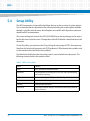
Boot Process . . . . . . . . . . . . . . . . . . . . . . . . . . . . . . . . . . . . . . . . . . . . . . . . . . . . . . . . . . . . . . . . . . . . . . . 71
Initiating Setup . . . . . . . . . . . . . . . . . . . . . . . . . . . . . . . . . . . . . . . . . . . . . . . . . . . . . . . . . . . . . . . . . . . . . 71
Setup Utility . . . . . . . . . . . . . . . . . . . . . . . . . . . . . . . . . . . . . . . . . . . . . . . . . . . . . . . . . . . . . . . . . . . . . . . 72
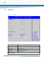
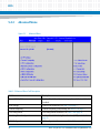
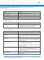
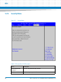
5.4.1 Main Menu . . . . . . . . . . . . . . . . . . . . . . . . . . . . . . . . . . . . . . . . . . . . . . . . . . . . . . . . . . . . . . . . . . 74
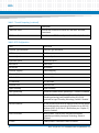
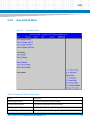
5.4.2 Advanced Menu . . . . . . . . . . . . . . . . . . . . . . . . . . . . . . . . . . . . . . . . . . . . . . . . . . . . . . . . . . . . . 76
5.4.3 Chipset Menu. . . . . . . . . . . . . . . . . . . . . . . . . . . . . . . . . . . . . . . . . . . . . . . . . . . . . . . . . . . . . . . . 83
5.4.4 Boot Menu . . . . . . . . . . . . . . . . . . . . . . . . . . . . . . . . . . . . . . . . . . . . . . . . . . . . . . . . . . . . . . . . . . 86
5.4.5 Security Menu . . . . . . . . . . . . . . . . . . . . . . . . . . . . . . . . . . . . . . . . . . . . . . . . . . . . . . . . . . . . . . . 88
5.4.6 Save and Exit Menu . . . . . . . . . . . . . . . . . . . . . . . . . . . . . . . . . . . . . . . . . . . . . . . . . . . . . . . . . . . 89
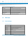
POST Codes . . . . . . . . . . . . . . . . . . . . . . . . . . . . . . . . . . . . . . . . . . . . . . . . . . . . . . . . . . . . . . . . . . . . . . . . 90
5.5.1 Status Code Ranges . . . . . . . . . . . . . . . . . . . . . . . . . . . . . . . . . . . . . . . . . . . . . . . . . . . . . . . . . . 90
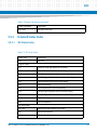
5.5.2 Standard Status Codes. . . . . . . . . . . . . . . . . . . . . . . . . . . . . . . . . . . . . . . . . . . . . . . . . . . . . . . . 91
5.5.2.1 SEC Status Codes . . . . . . . . . . . . . . . . . . . . . . . . . . . . . . . . . . . . . . . . . . . . . . . . . . . 91
5.5.2.2 PEI Status Codes . . . . . . . . . . . . . . . . . . . . . . . . . . . . . . . . . . . . . . . . . . . . . . . . . . . . 92
5.5.2.3 PEI Beep Codes . . . . . . . . . . . . . . . . . . . . . . . . . . . . . . . . . . . . . . . . . . . . . . . . . . . . . 95
5.5.2.4 DXE Status Codes . . . . . . . . . . . . . . . . . . . . . . . . . . . . . . . . . . . . . . . . . . . . . . . . . . . 96
5.5.2.5 DXE Beep Codes . . . . . . . . . . . . . . . . . . . . . . . . . . . . . . . . . . . . . . . . . . . . . . . . . . . . 99
5.5.2.6 CPU Exception Status Codess . . . . . . . . . . . . . . . . . . . . . . . . . . . . . . . . . . . . . . . . . 99
5.5.2.7 ASL Status Codes . . . . . . . . . . . . . . . . . . . . . . . . . . . . . . . . . . . . . . . . . . . . . . . . . . 100
5.5.2.8 OEM-reserved Status Code Ranges . . . . . . . . . . . . . . . . . . . . . . . . . . . . . . . . . . . 101
Boot Order Support . . . . . . . . . . . . . . . . . . . . . . . . . . . . . . . . . . . . . . . . . . . . . . . . . . . . . . . . . . . . . . . . 101
Windows XP Installation . . . . . . . . . . . . . . . . . . . . . . . . . . . . . . . . . . . . . . . . . . . . . . . . . . . . . . . . . . . . 102
Graphic Driver . . . . . . . . . . . . . . . . . . . . . . . . . . . . . . . . . . . . . . . . . . . . . . . . . . . . . . . . . . . . . . . . . . . . 102
BIOS Update . . . . . . . . . . . . . . . . . . . . . . . . . . . . . . . . . . . . . . . . . . . . . . . . . . . . . . . . . . . . . . . . . . . . . . 102
Operating System and Driver Support . . . . . . . . . . . . . . . . . . . . . . . . . . . . . . . . . . . . . . . . . . . . . . . . . 105
6.1
Supported Operating Systems . . . . . . . . . . . . . . . . . . . . . . . . . . . . . . . . . . . . . . . . . . . . . . . . . . . . . . 105
NITX-315/NITX-315-ET Installation and Use (6806800L71D)
5
Contents
Contents
A
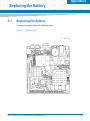
Replacing the Battery . . . . . . . . . . . . . . . . . . . . . . . . . . . . . . . . . . . . . . . . . . . . . . . . . . . . . . . . . . . . . . . . 107
A.1
B
Replacing the Battery . . . . . . . . . . . . . . . . . . . . . . . . . . . . . . . . . . . . . . . . . . . . . . . . . . . . . . . . . . . . . . 107
Related Documentation . . . . . . . . . . . . . . . . . . . . . . . . . . . . . . . . . . . . . . . . . . . . . . . . . . . . . . . . . . . . . . 109
B.1
Artesyn Embedded Technologies - Embedded Computing Documentation . . . . . . . . . . . . . . . 109
Safety Notes . . . . . . . . . . . . . . . . . . . . . . . . . . . . . . . . . . . . . . . . . . . . . . . . . . . . . . . . . . . . . . . . . . . . . . . . . . . . 111
Sicherheitshinweise . . . . . . . . . . . . . . . . . . . . . . . . . . . . . . . . . . . . . . . . . . . . . . . . . . . . . . . . . . . . . . . . . . . . . 115
6
NITX-315/NITX-315-ET Installation and Use (6806800L71D)
List of Tables
Table 1-1
Table 1-2
Table 1-3
Table 1-4
Table 1-5
Table 2-1
Table 2-2
Table 2-3
Table 2-4
Table 2-5
Table 3-1
Table 3-2
Table 3-3
Table 3-4
Table 3-5
Table 3-6
Table 3-7
Table 3-8
Table 3-9
Table 3-10
Table 3-11
Table 3-12
Table 3-13
Table 3-14
Table 3-15
Table 3-16
Table 3-17
Table 3-18
Table 3-19
Table 3-20
Table 3-21
Table 3-22
Table 3-23
Table 3-24
Table 3-25
Table 4-1
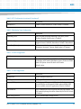
Key Features of the NITX-315 . . . . . . . . . . . . . . . . . . . . . . . . . . . . . . . . . . . . . . . . . . . . . . . . . . . . 19
Key Features of the NITX-315-ET . . . . . . . . . . . . . . . . . . . . . . . . . . . . . . . . . . . . . . . . . . . . . . . . . 21
Board Standard Compliances . . . . . . . . . . . . . . . . . . . . . . . . . . . . . . . . . . . . . . . . . . . . . . . . . . . . 22
Available Board Variants . . . . . . . . . . . . . . . . . . . . . . . . . . . . . . . . . . . . . . . . . . . . . . . . . . . . . . . . 27
Available Board Accessories . . . . . . . . . . . . . . . . . . . . . . . . . . . . . . . . . . . . . . . . . . . . . . . . . . . . . 27
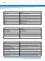
Environmental Requirements of NITX-315 . . . . . . . . . . . . . . . . . . . . . . . . . . . . . . . . . . . . . . . . . 29
Environmental Requirements of NITX-315-ET . . . . . . . . . . . . . . . . . . . . . . . . . . . . . . . . . . . . . . 30
Critical temperature Spots for NITX-315 and NITX-315-ET . . . . . . . . . . . . . . . . . . . . . . . . . . . 30
NITX-315 Power Dissipation . . . . . . . . . . . . . . . . . . . . . . . . . . . . . . . . . . . . . . . . . . . . . . . . . . . . . 31
Onboard LED Definition . . . . . . . . . . . . . . . . . . . . . . . . . . . . . . . . . . . . . . . . . . . . . . . . . . . . . . . . . 35
S2 Switch Settings . . . . . . . . . . . . . . . . . . . . . . . . . . . . . . . . . . . . . . . . . . . . . . . . . . . . . . . . . . . . . 43
LVDS Header Pin Definition (P28) . . . . . . . . . . . . . . . . . . . . . . . . . . . . . . . . . . . . . . . . . . . . . . . . 43
LVDS Inverter Header Pin Definition . . . . . . . . . . . . . . . . . . . . . . . . . . . . . . . . . . . . . . . . . . . . . . 44
LVDS Power Connector Pin Definition . . . . . . . . . . . . . . . . . . . . . . . . . . . . . . . . . . . . . . . . . . . . . 44
LVDS Power Jumper Pin Definition . . . . . . . . . . . . . . . . . . . . . . . . . . . . . . . . . . . . . . . . . . . . . . . . 44
USB Client Header Pin Definition . . . . . . . . . . . . . . . . . . . . . . . . . . . . . . . . . . . . . . . . . . . . . . . . . 45
CPU JTAG Header Pin Definition . . . . . . . . . . . . . . . . . . . . . . . . . . . . . . . . . . . . . . . . . . . . . . . . . . 45
USB Header Pin Definition . . . . . . . . . . . . . . . . . . . . . . . . . . . . . . . . . . . . . . . . . . . . . . . . . . . . . . . 45
eUSB Pin Header Definition . . . . . . . . . . . . . . . . . . . . . . . . . . . . . . . . . . . . . . . . . . . . . . . . . . . . . . 46
Audio Header Pin Definition . . . . . . . . . . . . . . . . . . . . . . . . . . . . . . . . . . . . . . . . . . . . . . . . . . . . . 47
CAN Bus Header Pin Definition . . . . . . . . . . . . . . . . . . . . . . . . . . . . . . . . . . . . . . . . . . . . . . . . . . . 47
SPI Program Header Pin Definition . . . . . . . . . . . . . . . . . . . . . . . . . . . . . . . . . . . . . . . . . . . . . . . 48
Full Wire RS232 Header Pin Definition . . . . . . . . . . . . . . . . . . . . . . . . . . . . . . . . . . . . . . . . . . . . 48
Two Wire RS232 Header . . . . . . . . . . . . . . . . . . . . . . . . . . . . . . . . . . . . . . . . . . . . . . . . . . . . . . . . 49
SDIO Header Pin Definition . . . . . . . . . . . . . . . . . . . . . . . . . . . . . . . . . . . . . . . . . . . . . . . . . . . . . . 49
Battery Header Pin Definition . . . . . . . . . . . . . . . . . . . . . . . . . . . . . . . . . . . . . . . . . . . . . . . . . . . . 50
Front Panel Header Pin Definition . . . . . . . . . . . . . . . . . . . . . . . . . . . . . . . . . . . . . . . . . . . . . . . . 50
GPIO Header Pin Definition . . . . . . . . . . . . . . . . . . . . . . . . . . . . . . . . . . . . . . . . . . . . . . . . . . . . . . 51
TPM Header (P8) Pin Definition . . . . . . . . . . . . . . . . . . . . . . . . . . . . . . . . . . . . . . . . . . . . . . . . . . 51
CPU FAN Header Pin Definition . . . . . . . . . . . . . . . . . . . . . . . . . . . . . . . . . . . . . . . . . . . . . . . . . . 52
ATX 4-Pin Power Header Pin Definition . . . . . . . . . . . . . . . . . . . . . . . . . . . . . . . . . . . . . . . . . . . . 53
SATA Power Header Pin Definition . . . . . . . . . . . . . . . . . . . . . . . . . . . . . . . . . . . . . . . . . . . . . . . . 53
I2C Header Pin Definition . . . . . . . . . . . . . . . . . . . . . . . . . . . . . . . . . . . . . . . . . . . . . . . . . . . . . . . 53
J9 SATA Pin Definition . . . . . . . . . . . . . . . . . . . . . . . . . . . . . . . . . . . . . . . . . . . . . . . . . . . . . . . . . . . 54
Onboard LEDs . . . . . . . . . . . . . . . . . . . . . . . . . . . . . . . . . . . . . . . . . . . . . . . . . . . . . . . . . . . . . . . . . 55
Tunnel Creek Processor Features . . . . . . . . . . . . . . . . . . . . . . . . . . . . . . . . . . . . . . . . . . . . . . . . . 58
NITX-315/NITX-315-ET Installation and Use (6806800L71D)
7
List of Tables
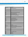
Table 4-2
Table 4-3
Table 4-4
Table 4-5
Table 5-1
Table 5-2
Table 5-3
Table 5-4
Table 5-5
Table 5-6
Table 5-7
Table 5-8
Table 5-9
Table 5-10
Table 5-11
Table 5-12
Table 5-13
Table 5-14
Table 5-15
Table 5-16
Table 5-17
Table 5-18
Table 5-19
Table 5-20
Table 5-21
Table 5-22
Table 5-23
Table 5-24
Table 5-25
Table 5-26
Table 5-27
Table 5-28
Table 5-29
Table 5-30
Table 5-31
Table 5-32
8
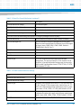
I2C Device Address . . . . . . . . . . . . . . . . . . . . . . . . . . . . . . . . . . . . . . . . . . . . . . . . . . . . . . . . . . . . . 65
TNC GPIO Definition . . . . . . . . . . . . . . . . . . . . . . . . . . . . . . . . . . . . . . . . . . . . . . . . . . . . . . . . . . . . 67
Topcliff GPIO Configuration . . . . . . . . . . . . . . . . . . . . . . . . . . . . . . . . . . . . . . . . . . . . . . . . . . . . . . 67
Clock Assignments . . . . . . . . . . . . . . . . . . . . . . . . . . . . . . . . . . . . . . . . . . . . . . . . . . . . . . . . . . . . . 69
BIOS Primary Menu . . . . . . . . . . . . . . . . . . . . . . . . . . . . . . . . . . . . . . . . . . . . . . . . . . . . . . . . . . . . . 72
Aptio Navigation . . . . . . . . . . . . . . . . . . . . . . . . . . . . . . . . . . . . . . . . . . . . . . . . . . . . . . . . . . . . . . . 73
Main Menu Field Description . . . . . . . . . . . . . . . . . . . . . . . . . . . . . . . . . . . . . . . . . . . . . . . . . . . . . 74
Platform Information . . . . . . . . . . . . . . . . . . . . . . . . . . . . . . . . . . . . . . . . . . . . . . . . . . . . . . . . . . . 75
Advanced Menu Field Description . . . . . . . . . . . . . . . . . . . . . . . . . . . . . . . . . . . . . . . . . . . . . . . . 76
ACPI Settings . . . . . . . . . . . . . . . . . . . . . . . . . . . . . . . . . . . . . . . . . . . . . . . . . . . . . . . . . . . . . . . . . . 77
Trusted Computing . . . . . . . . . . . . . . . . . . . . . . . . . . . . . . . . . . . . . . . . . . . . . . . . . . . . . . . . . . . . . 77
CPU Configuration . . . . . . . . . . . . . . . . . . . . . . . . . . . . . . . . . . . . . . . . . . . . . . . . . . . . . . . . . . . . . 78
Watchdog Timer Configuration . . . . . . . . . . . . . . . . . . . . . . . . . . . . . . . . . . . . . . . . . . . . . . . . . . 79
SDIO Configuration . . . . . . . . . . . . . . . . . . . . . . . . . . . . . . . . . . . . . . . . . . . . . . . . . . . . . . . . . . . . . 79
USB Configuration . . . . . . . . . . . . . . . . . . . . . . . . . . . . . . . . . . . . . . . . . . . . . . . . . . . . . . . . . . . . . . 79
LM80 H/W Monitor . . . . . . . . . . . . . . . . . . . . . . . . . . . . . . . . . . . . . . . . . . . . . . . . . . . . . . . . . . . . . 80
EMC2103 H/W Monitor . . . . . . . . . . . . . . . . . . . . . . . . . . . . . . . . . . . . . . . . . . . . . . . . . . . . . . . . . 80
Serial Port Console Redirection . . . . . . . . . . . . . . . . . . . . . . . . . . . . . . . . . . . . . . . . . . . . . . . . . . 80
COM0 Console Redirection Settings . . . . . . . . . . . . . . . . . . . . . . . . . . . . . . . . . . . . . . . . . . . . . . 81
Chipset Menu Field Descriptions . . . . . . . . . . . . . . . . . . . . . . . . . . . . . . . . . . . . . . . . . . . . . . . . . 83
North Bridge Chipset Configuration . . . . . . . . . . . . . . . . . . . . . . . . . . . . . . . . . . . . . . . . . . . . . . 83
Boot Display Configuration . . . . . . . . . . . . . . . . . . . . . . . . . . . . . . . . . . . . . . . . . . . . . . . . . . . . . . 84
South Bridge Chipset Configuration . . . . . . . . . . . . . . . . . . . . . . . . . . . . . . . . . . . . . . . . . . . . . . 84
PCI Express Ports Configuration > PCI Express Root Port . . . . . . . . . . . . . . . . . . . . . . . . . . . . . 85
IOH Configuration . . . . . . . . . . . . . . . . . . . . . . . . . . . . . . . . . . . . . . . . . . . . . . . . . . . . . . . . . . . . . . 85
Wake On Lan Configuration . . . . . . . . . . . . . . . . . . . . . . . . . . . . . . . . . . . . . . . . . . . . . . . . . . . . . 85
Boot Menu Field Description . . . . . . . . . . . . . . . . . . . . . . . . . . . . . . . . . . . . . . . . . . . . . . . . . . . . . 86
Security Menu Field Description . . . . . . . . . . . . . . . . . . . . . . . . . . . . . . . . . . . . . . . . . . . . . . . . . . 88
Save and Exit Menu Field Description . . . . . . . . . . . . . . . . . . . . . . . . . . . . . . . . . . . . . . . . . . . . . 89
Status Code Ranges . . . . . . . . . . . . . . . . . . . . . . . . . . . . . . . . . . . . . . . . . . . . . . . . . . . . . . . . . . . . 90
SEC Status Codes . . . . . . . . . . . . . . . . . . . . . . . . . . . . . . . . . . . . . . . . . . . . . . . . . . . . . . . . . . . . . . . 91
PEI Status Codes . . . . . . . . . . . . . . . . . . . . . . . . . . . . . . . . . . . . . . . . . . . . . . . . . . . . . . . . . . . . . . . 92
PEI Beep Codes . . . . . . . . . . . . . . . . . . . . . . . . . . . . . . . . . . . . . . . . . . . . . . . . . . . . . . . . . . . . . . . . 95
DXE Status Codes . . . . . . . . . . . . . . . . . . . . . . . . . . . . . . . . . . . . . . . . . . . . . . . . . . . . . . . . . . . . . . 96
DXE Beep Codes . . . . . . . . . . . . . . . . . . . . . . . . . . . . . . . . . . . . . . . . . . . . . . . . . . . . . . . . . . . . . . . 99
CPU Exception Status Codes . . . . . . . . . . . . . . . . . . . . . . . . . . . . . . . . . . . . . . . . . . . . . . . . . . . . . 99
NITX-315/NITX-315-ET Installation and Use (6806800L71D)
List of Tables
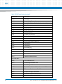
Table 5-33
Table 5-34
Table B-1
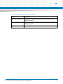
ASL Status Codes . . . . . . . . . . . . . . . . . . . . . . . . . . . . . . . . . . . . . . . . . . . . . . . . . . . . . . . . . . . . . 100
OEM-reserved Status Code Ranges . . . . . . . . . . . . . . . . . . . . . . . . . . . . . . . . . . . . . . . . . . . . . . 101
Artesyn Embedded Technologies - Embedded Computing Publications . . . . . . . . . . . . . 109
NITX-315/NITX-315-ET Installation and Use (6806800L71D)
9
List of Tables
10
NITX-315/NITX-315-ET Installation and Use (6806800L71D)
List of Figures
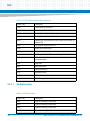
Figure 1-1
Figure 1-2
Figure 1-3
Figure 1-4
Figure 2-1
Figure 2-2
Figure 2-3
Figure 2-4
Figure 2-5
Figure 3-1
Figure 3-2
Figure 4-1
Figure 4-2
Figure 4-3
Figure 4-4
Figure 4-5
Figure 4-6
Figure 4-7
Figure 5-1
Figure 5-2
Figure 5-3
Figure 5-4
Figure 5-5
Figure 5-6
Figure A-1
NITX-315 Declaration of Conformity . . . . . . . . . . . . . . . . . . . . . . . . . . . . . . . . . . . . . . . 23
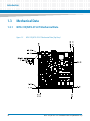
NITX-315/NITX-315-ET Mechanical Data (Top View) . . . . . . . . . . . . . . . . . . . . . . . . . 24
NITX-315/NITX-315-ET Mechanical Data (Side View) . . . . . . . . . . . . . . . . . . . . . . . . 25
Serial Number Location . . . . . . . . . . . . . . . . . . . . . . . . . . . . . . . . . . . . . . . . . . . . . . . . . . 26
Board Thermal Management Diagram . . . . . . . . . . . . . . . . . . . . . . . . . . . . . . . . . . . . . 34
eUSB Flash Disk Installation and Removal . . . . . . . . . . . . . . . . . . . . . . . . . . . . . . . . . . . 36
J9 22-pin SATA connector . . . . . . . . . . . . . . . . . . . . . . . . . . . . . . . . . . . . . . . . . . . . . . . . 38
Serial ATA HDD . . . . . . . . . . . . . . . . . . . . . . . . . . . . . . . . . . . . . . . . . . . . . . . . . . . . . . . . . 38
Slim Lite SSD (MO-297) . . . . . . . . . . . . . . . . . . . . . . . . . . . . . . . . . . . . . . . . . . . . . . . . . . 39
NITX-315/NITX-315-ET Module Components . . . . . . . . . . . . . . . . . . . . . . . . . . . . . . . 41
NITX-315/NITX-315-ET Module Components (Rear View) . . . . . . . . . . . . . . . . . . . . 42
Block Diagram for NITX-315/NITX-315-ET . . . . . . . . . . . . . . . . . . . . . . . . . . . . . . . . . . 57
PCI-E Connection Diagram . . . . . . . . . . . . . . . . . . . . . . . . . . . . . . . . . . . . . . . . . . . . . . . 60
SDIO Link Connection Diagram . . . . . . . . . . . . . . . . . . . . . . . . . . . . . . . . . . . . . . . . . . . 61
USB ports connections diagram . . . . . . . . . . . . . . . . . . . . . . . . . . . . . . . . . . . . . . . . . . . 62
USB Flash Connector Pin Definition . . . . . . . . . . . . . . . . . . . . . . . . . . . . . . . . . . . . . . . . 63
Board I2C Device Connection Diagram . . . . . . . . . . . . . . . . . . . . . . . . . . . . . . . . . . . . 65
Clock Distribution of NITX-315/NITX-315-ET . . . . . . . . . . . . . . . . . . . . . . . . . . . . . . . 69
Main Menu . . . . . . . . . . . . . . . . . . . . . . . . . . . . . . . . . . . . . . . . . . . . . . . . . . . . . . . . . . . . . 74
Advanced Menu . . . . . . . . . . . . . . . . . . . . . . . . . . . . . . . . . . . . . . . . . . . . . . . . . . . . . . . . . 76
Chipset Menu . . . . . . . . . . . . . . . . . . . . . . . . . . . . . . . . . . . . . . . . . . . . . . . . . . . . . . . . . . . 83
Boot Menu . . . . . . . . . . . . . . . . . . . . . . . . . . . . . . . . . . . . . . . . . . . . . . . . . . . . . . . . . . . . . 86
Security Menu . . . . . . . . . . . . . . . . . . . . . . . . . . . . . . . . . . . . . . . . . . . . . . . . . . . . . . . . . . 88
Save and Exit Menu . . . . . . . . . . . . . . . . . . . . . . . . . . . . . . . . . . . . . . . . . . . . . . . . . . . . . . 89
Battery Location . . . . . . . . . . . . . . . . . . . . . . . . . . . . . . . . . . . . . . . . . . . . . . . . . . . . . . . 107
NITX-315/NITX-315-ET Installation and Use (6806800L71D)
11
List of Figures
12
NITX-315/NITX-315-ET Installation and Use (6806800L71D)
About this Manual
Overview of Contents
This manual is divided into the following chapters and appendices.
Introduction gives an overview of the features of the product, standard compliances,
mechanical data, and ordering information.
Hardware Preparation and Installation outlines the installation requirements, hardware
accessories, switch settings, and installation procedures.
Controls, LEDs, and Connectors describes external interfaces of the board. This include
connectors and LEDs.
Functional Description includes a block diagram and functional description of major
components of the product.
Replacing the Battery contains the procedures for replacing the battery.
Related Documentation provides a listing of related product documentation,
manufacturer’s documents, and industry standard specifications.
Safety Notes summarizes the safety instructions in the manual.
Sicherheitshinweise is a German translation of the Safety Notes chapter.
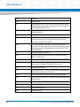
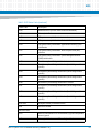
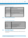
Abbreviations
This document uses the following abbreviations:
TERM
MEANING
A
Amps
AC '97
Audio CODEC (Coder-Decoder)
ACPI
Advanced Configuration Power Interface - software standard to
implement power saving modes in PC-AT systems
EEPROM
Electrically Erasable Programmable Read-Only Memory
GPI
General Purpose Input
GPIO
General Purpose Input Output
GPO
General Purpose Output
NITX-315/NITX-315-ET Installation and Use (6806800L71D)
13
About this Manual
14
About this Manual
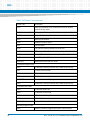
TERM
MEANING
HDD
Hard Disk Drive
I2C
Inter Integrated Circuit - 2 wire (clock and data) signaling scheme
allowing communication between integrated circuits, primarily used
to read and load registers values.
IDE
Integrated Device Electronics - parallel interface for hard disk drives also known as PATA
JTAG
Joint Test Action Group
LPC
Low Pin-Count Interface: a low speed interface used for peripheral
circuits such as Super I/O controllers, which typically combine
legacy-device support into a single IC.
LVDS
Low Voltage Differential Signaling - widely used as a physical
interface for TFT flat panels. LVDS can be used for many high-speed
signaling applications. In this document, it refers only to TFT flatpanel applications.
PCI
Peripheral Component Interface
PCI-E
Peripheral Component Interface Express - next-generation high
speed Serialized I/O bus
PHY
Ethernet controller physical layer device
Pin-out Type
A reference to one of five COM ExpressTM definitions for what signals
appear on the COM ExpressTM module connector pins.
SDD
Subsystem Device Driver
SPD
Serial Presence Detect - refers to serial EEPROM on DRAMs that has
DRAM module configuration information
SATA
Serial AT Attachment: serial-interface standard for hard disks
SDVO
Serialized Digital Video Output - Intel defined format for digital video
output that can
SSD
Solid State Drive
USB
Universal Serial Bus
VGA
Video Graphics Adapter
WDT
Watch Dog Timer.
NITX-315/NITX-315-ET Installation and Use (6806800L71D)
About this Manual
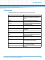
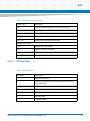
Conventions
The following table describes the conventions used throughout this manual.
Notation
Description
0x00000000
Typical notation for hexadecimal numbers (digits are
0 through F), for example used for addresses and
offsets
0b0000
Same for binary numbers (digits are 0 and 1)
bold
Used to emphasize a word
Screen
Used for on-screen output and code related elements
or commands in body text
Courier + Bold
Used to characterize user input and to separate it
from system output
Reference
Used for references and for table and figure
descriptions
File > Exit
Notation for selecting a submenu
<text>
Notation for variables and keys
[text]
Notation for software buttons to click on the screen
and parameter description
...
Repeated item for example node 1, node 2, ..., node
12
.
Omission of information from example/command
that is not necessary at the time being
.
.
..
Ranges, for example: 0..4 means one of the integers
0,1,2,3, and 4 (used in registers)
|
Logical OR
NITX-315/NITX-315-ET Installation and Use (6806800L71D)
15
About this Manual
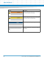
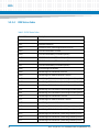
Notation
About this Manual
Description
Indicates a hazardous situation which, if not avoided,
could result in death or serious injury
Indicates a hazardous situation which, if not avoided,
may result in minor or moderate injury
Indicates a property damage message
No danger encountered. Pay attention to important
information
16
NITX-315/NITX-315-ET Installation and Use (6806800L71D)
About this Manual
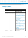
Summary of Changes
This manual has been revised and replaces all prior editions.
Part Number
Publication Date
Description
6806800L71D
August 2014
Re-branded to Artesyn template.
Added Declaration of Conformity.
6806800L71C
December 2012
Updated Chapter 1, Standard Compliances, on
page 22.
6806800L71B
October 2011
Updated Chapter 5, BIOS, on page 71
Updated Figure "NITX-315/NITX-315-ET
Mechanical Data (Top View)" on page 24 and
Figure "NITX-315/NITX-315-ET Mechanical Data
(Side View)" on page 25
Added Table "Environmental Requirements of
NITX-315-ET" on page 30
Updated Table "Environmental Requirements of
NITX-315" on page 29
Updated Table "Critical temperature Spots for
NITX-315 and NITX-315-ET" on page 30
Updated Figure "Board Thermal Management
Diagram" on page 34
Added Figure "eUSB Flash Disk Installation and
Removal" on page 36
Added Chapter 2, SATA HDD and Slim Lite SSD (MO297) Connection and Removal, on page 37
Updated Chapter 3, CPU JTAG header (P20) Optional, on page 45 and Chapter 3, Audio Header
(P12), on page 47
Added Table "J9 SATA Pin Definition" on page 54
Removed Chapter 4.19 Reset Control Logic
6806800L71A
March 2011
NITX-315/NITX-315-ET Installation and Use (6806800L71D)
Preliminary Release
17
About this Manual
18
About this Manual
NITX-315/NITX-315-ET Installation and Use (6806800L71D)
Chapter 1
Introduction
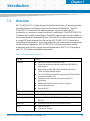
1.1
Overview
NITX-315/NITX-315-ET is a highly integrated Small Form Factor Nano-ITX board based on the
Queensbay Platform, including the Tunnel Creek processor and Topcliff IOH. The NITX315/NITX-315-ET incorporates the standard processor, memory, graphics and I/O
functionality, as is common as a small form factor PC motherboard. The NITX-315/NITX-315ET operates with or without a local display. Standard PC expansion ports are also available on
the rear panel along with additional USB ports, SATA and LVDS via headers on the board as well
as a single PCIExpress expansion slot. Because the NITX-315/NITX-315-ET is based on the
latest Intel Queensbay platform, it has a long product life cycle, lower power consumption and
suitable for fanless applications. NITX-315/NITX-315-ET performs well within extended
temperature ranges for more rugged commercial applications. NITX-315-ET is designed to
meet -20 - 70 °C ambient temperature requirement.
Table 1-1 Key Features of the NITX-315
Function
Features
Processor
Intel Tunnel Creek processor E640 1.0GHz
Single channel memory controller supporting DDR2 800 MT/s
memory down
Both LVDS up to 1280x768 @ 60Hz and SDVO output up to
1280x1024 @ 85Hz output support
Four x1 lane PCI Express root ports supporting the PCI Express Base
Specification, Revision 1.0a
Implements an LPC interface as described in the LPC1.1
specification
SMBus Host Controller based on Version 1.0 support
Serial Peripheral Interface
Integrated WDT
IOH
Intel Topcliff IOH
BIOS Device
One 4MB SPI boot device
Memory
Supports 1GB 32-bit DDR2 800 MHz non-ECC memory down on
NITX-315
eUSB Flash
An optional eUSB flash on one 2x5 header on board
PCI-E
One PCI-E x1 slot
One Mini PCI-E socket
NITX-315/NITX-315-ET Installation and Use (6806800L71D)
19
Introduction
Table 1-1 Key Features of the NITX-315 (continued)
Function
Features
SATA
One internal SATA connector (7-pin)
One standard 22 (15power+7signal) pins SATA connector for JEDEC
MOS-297A internal slim lite SDD application
MicroSD Card
One Micro SD card slot
USB
Two Hi-Speed USB 2.0 interfaces to USB 2.0 Type A connectors
accessible in the back-panel I/O region
Four Hi-Speed USB 2.0 interfaces to two 9-pin dual-USB headers,
one is optionally connecting mini PCI-E slot
One USB client port on an internal header
Ethernet
Supports 10/100/1000 Ethernet based on Marvell 88E1111
RS232
One full signal(8-wire) COM through RS-232 transceiver to header
Three UART(2-wire) through RS-232 transceiver to one internal
header
CAN bus
One set of CAN bus on one 4-pin internal header
Video
One single-channel LVDS 20-pin header
One VGA port derived from the SDVO port
Audio
One HDA codec with one Line-in, one Line-out port
TPM ( LPC )
One TPM header for TPM 1.2 module support
Watchdog
One integrated watchdog with sepectable options from
approximately 1 minute to 10 minutes
Form factor
Nano-ITX , 120 mm X 120 mm form factor
OS
Supports Microsoft Windows XP Professional
Supports Microsoft Windows 7
Supports Windows Embedded 7 Standard
Supports MeeGo Linux
0-60 °C
Temperature
20
NITX-315/NITX-315-ET Installation and Use (6806800L71D)
Introduction
Table 1-2 Key Features of the NITX-315-ET
Function
Features
Processor
Intel Tunnel Creek processor E640T 1.0GHz
Single channel memory controller supporting DDR2 800 MT/s
memory down
Both LVDS up to 1280x768 @ 60Hz and SDVO output up to
1280x1024 @ 85Hz output support
Four x1 lane PCI Express root ports supporting the PCI Express Base
Specification, Revision 1.0a
Implements an LPC interface as described in the LPC1.1
specification
SMBus Host Controller based on Version 1.0 support
Serial Peripheral Interface
Integrated WDT
IOH
Intel Topcliff IOH
BIOS Device
One 4MB SPI boot device
Memory
Supports 1GB 32-bit DDR2 800 MHz non-ECC memory down on
NITX-315-ET
eUSB Flash
An optional eUSB flash on one 2x5 header on board
PCI-E
One PCI-E x1 slot
One Mini PCI-E socket
One internal SATA connector (7-pin)
One standard 22 (15power+7signal) pins SATA connector for JEDEC
MOS-297A internal slim lite SDD application
MicroSD Card
One Micro SD card slot
USB
Two Hi-Speed USB 2.0 interfaces to USB 2.0 Type A connectors
accessible in the back-panel I/O region
Four Hi-Speed USB 2.0 interfaces to two 9-pin dual-USB headers,
one is optionally connecting mini PCI-E slot
One USB client port on an internal header
Ethernet
Supports 10/100/1000 Ethernet based on Marvell 88E1111
RS232
One full signal(8-wire) COM through RS-232 transceiver to header
Three UART(2-wire) through RS-232 transceiver to one internal
header
SATA
NITX-315/NITX-315-ET Installation and Use (6806800L71D)
21
Introduction
Table 1-2 Key Features of the NITX-315-ET (continued)
Function
Features
CAN bus
One set of CAN bus on one 4-pin internal header
Video
One single-channel LVDS 20-pin header
One VGA port derived from the SDVO port
Audio
One HDA codec with one Line-in, one Line-out port
TPM ( LPC )
One TPM header for TPM 1.2 module support
Watchdog
One integrated watchdog with sepectable options from
approximately 1 minute to 10 minutes
Form factor
Nano-ITX , 120 mm X 120 mm form factor
OS
Supports Microsoft Windows XP Professional
Supports Microsoft Windows 7
Supports Windows Embedded 7 Standard
Supports MeeGo Linux
- 20 - 70 °C
Temperature
1.2
Standard Compliances
The product is designed to meet the following standards.
Table 1-3 Board Standard Compliances
22
Standard
Description
EMC Compliance Standards
Class B (FCC, VCCI, AS/NZ), EN 55024 and 55022
Safety Standards
UL, CSA, Ctick
NITX-315/NITX-315-ET Installation and Use (6806800L71D)
Introduction
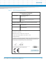
Figure 1-1
NITX-315 Declaration of Conformity
EC Declaration of Conformity
According to EN 17050-1:2004
Manufacturer’s Name:
Artesyn Embedded Technologies
Embedded Computing
Manufacturer’s Address:
Zhongshan General Carton Box Factory Co. Ltd. No 62, Qi
Guan Road West, Shiqi District, 528400 Zhongshan City
Guangdong, PRC
Declares that the following product, in accordance with the requirements of 2004/108/EC, 2006/95/EC,
2011/65/EU and their amending directives,
Product:
ITE Computing Device
Model Name/Number:
NITX-315, NITX-315-ET
has been designed and manufactured to the following specifications:
EN55022: 2006 + A1: 2007 Class B
EN55024: 1998 =A1; 2001 + A2: 2003(A1: 2001 + A2: 2003); 1998
IEC 60950-1:2005 (2nd Edition), EN60950-1: 2005 2nd Edition + A1: 2009
2011/65/EU RoHS Directive
As manufacturer we hereby declare that the product named above has been designed to comply with the relevant sections of the above referenced specifications. This product complies with the essential health and safety
requirements of the above specified directives. We have an internal production control system that ensures
compliance between the manufactured products and the technical documentation.
___________________________________________________
___08/26/2014______
Tom Tuttle, Manager, Product Testing Services
Date (MM/DD/YYYY)
NITX-315/NITX-315-ET Installation and Use (6806800L71D)
23
Introduction
1.3
Mechanical Data
1.3.1
NITX-315/NITX-315-ET Mechanical Data
120.00
113.65
NITX-315/NITX-315-ET Mechanical Data (Top View)
3.26
Figure 1-2
120.00
116.76
3.20 THROUGH HOLE
WITH
5.5mm PAD
BOTH SIDE
4 PLACE
86.98
3.00
3.00
24
116.76
2.75
0.00
0.00
NITX-315/NITX-315-ET Installation and Use (6806800L71D)
Introduction
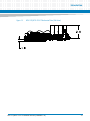
Figure 1-3
NITX-315/NITX-315-ET Mechanical Data (Side View)
30.22
5.15
NITX-315/NITX-315-ET Installation and Use (6806800L71D)
25
Introduction
1.4
Board Identification
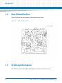
This section shows the serial number and its location on the board.
Figure 1-4
1.5
Serial Number Location
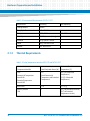
Ordering Information
Use the order numbers below when ordering board variants or board accessories.
26
NITX-315/NITX-315-ET Installation and Use (6806800L71D)
Introduction
1.5.1
Board Variants
The following table lists the product variants that are available upon release of this publication.
Table 1-4 Available Board Variants
1.5.2
Part Number
Description
NITX-315
NANO ITX 1.0 GHz
NITX-315-ET
NANO ITX 1.0 GHz, ET
Board Accessories
The following table lists the board accessories that are available upon release of this
publication.
Table 1-5 Available Board Accessories
Order Number
Description
KR8-PS01
DC POWER ADAPTER 60W
NITX-315/NITX-315-ET Installation and Use (6806800L71D)
27
Introduction
28
NITX-315/NITX-315-ET Installation and Use (6806800L71D)
Chapter 2
Hardware Preparation and Installation
2.1
Environmental and Power Requirements
2.1.1
Environmental Requirements
The following tables list the environmental requirements that the NITX-315 and NITX-315-ET
boards must meet when operated in your particular system configuration.
Operating temperatures refer to the temperature of the air circulating around the board and
not to the component temperature.
Product Damage
High humidity and condensation on surfaces cause short circuits.
Do not operate the system outside the specified environmental limits. Make sure the
product is completely dry and there is no moisture on any surface before applying power.
Table 2-1 Environmental Requirements of NITX-315
Requirement
Operating
Cooling Method
Fanless
Temp Cycle Class
-40-+85C:500cyc
Temperature
0-60C
Humidity
10-90% (non-condensing)
Vibration
.01 g^2/Hz @ 5-500Hz
Shock
20g 11ms sine or saw
Altitude
-60 - 4000 m ASL
NITX-315/NITX-315-ET Installation and Use (6806800L71D)
Non-Operating
-40-+85C
29
Hardware Preparation and Installation
Table 2-2 Environmental Requirements of NITX-315-ET
2.1.2
Requirement
Operating
Cooling Method
Fanless
Temp Cycle Class
-40-+85C:500cyc
Temperature
-20°C—70°C
Humidity
10-90% (non-condensing)
Vibration
.01 g^2/Hz @ 5-500Hz
Shock
20g 11ms sine or saw
Altitude
-60 - 4000 m ASL
Non-Operating
-40-+85C
Thermal Requirements
Table 2-3 Critical temperature Spots for NITX-315 and NITX-315-ET
Maximum Allowable
Component Identifier
Heat Dissipation Power (W)
Temperature (°C)
CPU:
3.6
Commercial Temperature:
(both Commercial
Temperature and Extended
Temperature)
90 (Tj of Commercial
Temperature )
Atom E640
Extended Temperature:
110 (Tj of Extended
Temperature)
Atom E640T
IOH: EG20T
1.55
115.7 (Tj)
Memory SDRAM
1
85 (Tc of Commercial version)
1GB
30
95 (Tc of Extended
Temperature version)
NITX-315/NITX-315-ET Installation and Use (6806800L71D)
Hardware Preparation and Installation
Contact your Artesyn sales representative for current information on the detailed thermal
information including airflow and resistance of the board.
System Overheating
Cooling Vents
Improper cooling can lead to system damage and can void the manufacturer's warranty.
To ensure proper cooling and undisturbed airflow through the system do not obstruct the
ventilation openings of the system. Make sure that the fresh air supply is not mixed with hot
exhaust from other devices.
Personal Injury
During operation, hot surfaces may be present on the heat sinks and the components of the
product.
To prevent injury from hot surface do not touch any of the exposed components or
heatsinks on the product when handing. Use the handle and face plate, where applicable, or
the board edge when removing the product from the enclosure.
2.1.3
Power Requirements
The following table describes the power dissipation of the NITX-315 and NITX-315-ET board.
Table 2-4 NITX-315 Power Dissipation
State
+12 V
VCC_RTC
G3 (AC off)
0
26.8μA
Idle (CMOS Setup)
0.8A
0
9.6w
Idle (Window XP SP3 X32)
0.78~8.87A
0
9.36w~10.44w
FullLoading (PTU+Burn In
Test)
0.9~0.96A
0
10.8w~11.52w
NITX-315/NITX-315-ET Installation and Use (6806800L71D)
Power consumption (w)
31
Hardware Preparation and Installation
Table 2-4 NITX-315 Power Dissipation (continued)
State
+12 V
VCC_RTC
Power consumption (w)
s5
0.038A (unplug ethernet)
0.155 A (plug ethernet)
0
0.456w (unplug
ethernet) 1.86w (plug
ethernet)
2.2
Unpacking and Inspecting the Board
Read all notices and cautions prior to unpacking the product.
Damage of Circuits
Electrostatic discharge and incorrect installation and removal can damage circuits or
shorten their life.
Before touching the board or electronic components, make sure that you are working in an
ESD-safe environment.
Shipment Inspection
1. Verify that you have received all items of your shipment.
2. Check for damage and report any damage or differences to customer service.
3. Remove the desiccant bag shipped together with the board and dispose of it
according to your country’s legislation.
Environmental Damage
Improperly disposing of used products may harm the environment.
Always dispose of used products according to your country’s legislation and manufacturer’s
instructions.
32
NITX-315/NITX-315-ET Installation and Use (6806800L71D)
Hardware Preparation and Installation
The product is thoroughly inspected before shipment. If any damage occurred during
transportation or any items are missing, contact customer service immediately.
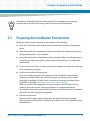
2.3
Preparing the Installation Environment
Before you install or replace components, pay attention to the following:
Wear an ESD-preventive wrist strap to prevent the static electricity from damaging the
device.
Keep the area where the components reside clean and keep the components away from
heat-generating devices, such as radiator.
Ensure that your sleeves are tightened or rolled up above the elbow. For safety purposes, it
is not recommended to wear jewelry, watch, glasses with metal frame, or clothes with
metal buttons.
Do not exert too much force, or insert or remove the components forcibly. Avoid damage
to the components or plug-ins.
Confirm the feasibility of the operation
There are available spare parts of the components to be installed or replaced in the
equipment warehouse. When the available spare parts are lacking, contact Artesyn
Embedded Technologies for help in time. For details on how to get help from Artesyn
Embedded Technologies, visit http://www.artesyn.com/computing/.
Make sure that the new components are in good condition, without defects such as
oxidation, chemical corrosion, missing components, or transportation damage.
By reading this document, you are familiar with how to install and replace the component
and master the skills required by the operation.
Check the environment
Make sure that the power supply, temperature, and humidity meet the operating
requirements for the board and its components. For details, refer to the respective system
documentation.
NITX-315/NITX-315-ET Installation and Use (6806800L71D)
33
Hardware Preparation and Installation
2.4
Prepare the parts and the tools
Prepare the components to be installed or replaced.
When you hold or transport the components, use the special antistatic package. Prepare
the cross screwdriver, screws, plastic supports, cooling gel, and ESD-preventive wrist
strap.
Confirm installation or changing position
Confirm the position where NITX-315/NITX-315-ET will be installed.
If a serious problem occurs and cannot be solved when you install or replace the
component, contact Artesyn Embedded Technologies for technical support.
Board Thermal Management and Placement
NITX-315/NITX-315-ET provides a thermal management strategy. This includes CPU junction
temperature monitoring, one on-board fan connector, and can take the corresponding action
to protect the system during catastrophic overheating.
The following diagram shows thermal management strategy:
Figure 2-1
34
Board Thermal Management Diagram
NITX-315/NITX-315-ET Installation and Use (6806800L71D)
Hardware Preparation and Installation
A PNP thermal transistor is integrated in Tunnel Creek; it is used as a diode and it connects to
an external digital thermal sensor (EMC2103). The CPU can get the data of junction
temperature through the SM bus. Note that this is an inaccurate value and the temperature
offset must be taken into account through the reading of the CPU’s MSR.
Intel Thermal Monitor: Intel thermal monitor controls processor temperature by modulating
(starting and stopping) the processor core clocks when the processor silicon reaches its
maximum operating temperature. Signal "PROCHOT #" is used in this mode, when the
processor temperature goes up to 110C, the PROCHOT# is output and active, it indicates that
the processor thermal control circuit is activated. A red LED D2 can show the "processor hot"
status.
When the CPU junction temperature is more than 125°C, CPU will assert the THERMTRIP#, and
the onboard logic will shut down the system power, the LED D8 shows this status.
Table 2-5 Onboard LED Definition
LED
Definition
Status
Description
D2
'PROCHOT' signal is active
ON
The CPU temperature goes up to 110°C
OFF
Normal status
ON
The CPU temperature goes up to 125°C
OFF
Normal status
D8
'THERMTRIP#' signal is active
NITX-315/NITX-315-ET Installation and Use (6806800L71D)
35
Hardware Preparation and Installation
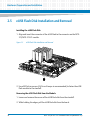
2.5
eUSB Flash Disk Installation and Removal
Installing the eUSB Flash Disk
1. Align and insert the connector of the eUSB Flash to the connector on the NITX315/NITX-315-ET module.
Figure 2-2
eUSB Flash Disk Installation and Removal
2. Use a M2.5x4 mm screw (0.4 N·m of torque is recommended) to fasten the eUSB
Flash module to the standoff.
Removing the eUSB Flash Disk from the Module
1. Loosen and remove the screws of the eUSB Flash disk from the standoff.
2. While holding the edges, pull the eUSB Flash disk from the board.
36
NITX-315/NITX-315-ET Installation and Use (6806800L71D)
Hardware Preparation and Installation
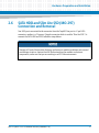
2.6
SATA HDD and Slim Lite SSD (MO-297)
Connection and Removal
Two SATA ports are routed to the connector from the Topcliff. One port is a 7-pin SATA
connector, another is a 15-power+7signals connector which is used for "Slim Lite SSD". To
connect the SATA HDD and SSD, follow the steps below:
Damage of Circuits Electrostatic discharge and incorrect module installation and removal
can damage circuits or shorten their life. Before touching the module or electronic
components, make sure that you are working in an ESD-safe environment.
NITX-315/NITX-315-ET Installation and Use (6806800L71D)
37
Hardware Preparation and Installation
1. Locate the J9 22-pin SATA connector on the underside of the NITX-315/NITX-315ET board.
Figure 2-3
J9 22-pin SATA connector
2. Connect one end of the SATA cable to the J9 22-pin SATA connector and the other
end to the SATA HDD or SSD device.
Figure 2-4
38
Serial ATA HDD
NITX-315/NITX-315-ET Installation and Use (6806800L71D)
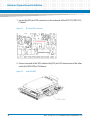
Hardware Preparation and Installation
Figure 2-5
Slim Lite SSD (MO-297)
HDD or SDD device should be fastened to a chassis or an enclosure.
NITX-315/NITX-315-ET Installation and Use (6806800L71D)
39
Hardware Preparation and Installation
40
NITX-315/NITX-315-ET Installation and Use (6806800L71D)
Chapter 3
Controls, LEDs, and Connectors
3.1
Board Layout
Figure 3-1
NITX-315/NITX-315-ET Module Components
NITX-315/NITX-315-ET Installation and Use (6806800L71D)
41
Controls, LEDs, and Connectors
Figure 3-2
42
NITX-315/NITX-315-ET Module Components (Rear View)
NITX-315/NITX-315-ET Installation and Use (6806800L71D)
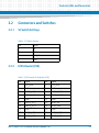
Controls, LEDs, and Connectors
3.2
Connectors and Switches
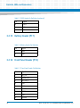
3.2.1
S2 Switch Settings
Table 3-1 S2 Switch Settings
3.2.2
Pin
Signal
1
NC
2
GND
3
PWR_SW
4
GND
LVDS Header (P28)
Table 3-2 LVDS Header Pin Definition (P28)
Pin
Signal
Pin
Signal
1
VCC_LVDS
2
VCC_LVDS
3
GND
4
GND
5
LVDS_A_A0_P
6
LVDS_A_CLK_P
7
LVDS_A_A0_N
8
LVDS_A_CLK_N
9
GND
10
GND
11
LVDS_A_A1_P
12
LDDC_CLK
13
LVDS_A_A1_N
14
LDDC_DATA
15
GND
16
GND
17
LVDS_A_A2_P
18
LVDS_A_A3_P
19
LVDS_A_A2_N
20
LVDS_A_A3_N
NITX-315/NITX-315-ET Installation and Use (6806800L71D)
43
Controls, LEDs, and Connectors
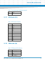
3.2.3
LVDS Backlight Header (P23)
Table 3-3 LVDS Inverter Header Pin Definition
3.2.4
Pin
Signal
1
VCC12V
2
LVDS_BKLT_EN
3
GND
4
LCD_BKL_ADJ
5
VCC5V
LVDS Power Header (P5)
Table 3-4 LVDS Power Connector Pin Definition
Pin
Signal
1
D33VS
2
VCC_LVDS_SEL
3
D50VS
Table 3-5 LVDS Power Jumper Pin Definition
Jumper setting
44
(Jumper:P5)
Configuration
P5 (1-2)
Using 3.3V to power the
LVDS panel
P5 (2-3)
Using 5V to power the
LVDS panel
NITX-315/NITX-315-ET Installation and Use (6806800L71D)
Controls, LEDs, and Connectors
3.2.5
USB client header (P18)
Table 3-6 USB Client Header Pin Definition
3.2.6
Pin
Signal
1
USB power detect
2
D-
3
D+
4
GND
CPU JTAG header (P20) - Optional
Table 3-7 CPU JTAG Header Pin Definition
3.2.7
Pin
Signal
1
XDP_TDI
2
CPU_TDI
3
INT_TDI
4
CPU_TDO
5
IO_TDO
6
XDP_TDO
USB Header (P6)
Table 3-8 USB Header Pin Definition
Pin
Signal
1
USB0_PWR
NITX-315/NITX-315-ET Installation and Use (6806800L71D)
45
Controls, LEDs, and Connectors
Table 3-8 USB Header Pin Definition (continued)
3.2.8
Pin
Signal
2
USB1_PWR
3
USB0_DN
4
USB1_DN
5
USB0_DP
6
USB1_DP
7
GND
8
GND
9
dummy
10
NC
eUSB Header (P2)
Table 3-9 eUSB Pin Header Definition
46
Pin
Signal
1
USB4_PWR
2
USB5_PWR
3
USB4_DN
4
USB5_DN
5
USB4_DP
6
USB5_DP
7
GND
8
GND
9
dummy
10
NC
NITX-315/NITX-315-ET Installation and Use (6806800L71D)
Controls, LEDs, and Connectors
3.2.9
Audio Header (P12)
Table 3-10 Audio Header Pin Definition
Pin
Signal
1
Dummy
2
GND
3
Dummy
4
NC
5
LOUT_R
6
Dummy
7
GND
8
Dummy
9
LOUT_L
10
LOUT_JD
3.2.10 CAN Bus Header (P15)
Table 3-11 CAN Bus Header Pin Definition
Pin
Signal
1
CAN_H
2
GND
3
CAN_L
4
VCC5
NITX-315/NITX-315-ET Installation and Use (6806800L71D)
47
Controls, LEDs, and Connectors
3.2.11 SPI Program Header (P21)
Table 3-12 SPI Program Header Pin Definition
Pin
Signal
1
V3V3_POWER
2
GND
3
SPI_CS
4
SPI_CLK
5
SPI_MISO
6
SPI_MOSI
7
NC
8
NC
3.2.12 Full Wire RS232 Header (P7)
Table 3-13 Full Wire RS232 Header Pin Definition
48
Pin
Signal
1
COM1A_DCD
2
COM1A_RXD
3
COM1A_TXD
4
COM1A_DTR
5
GND
6
COM1A_DSR
7
COM1A_RTS
8
COM1A_CTS
9
COM1A_RI-
NITX-315/NITX-315-ET Installation and Use (6806800L71D)
Controls, LEDs, and Connectors
3.2.13 Two Wire RS232 Header (P14)
Table 3-14 Two Wire RS232 Header
Pin
Signal
1
COM2_RXD_232
2
COM2_TXD_232
3
GND
4
GND
5
COM3_RXD_232
6
COM3_TXD_232
7
GND
8
GND
9
COM4_RXD_232
10
COM4_RXD_232
3.2.14 SDIO Header (P16)
Table 3-15 SDIO Header Pin Definition
Pin
Signal
1
DAT3
2
CMD
3
VDD
4
GND
5
CLK
6
DAT0
7
DAT1
NITX-315/NITX-315-ET Installation and Use (6806800L71D)
49
Controls, LEDs, and Connectors
Table 3-15 SDIO Header Pin Definition (continued)
Pin
Signal
8
DAT2
9
CD#
10
WP
3.2.15 Battery Header (P17)
Table 3-16 Battery Header Pin Definition
Pin
Signal
1
VBAT
2
GND
3.2.16 Front Panel Header (P19)
Table 3-17 Front Panel Header Pin Definition
50
Pin
Signal
1
HD_LED
2
POWER_LED
3
HD_LED_N
4
GND
5
GND
6
PWRBTN
7
RESET
8
GND
9
Dummy
NITX-315/NITX-315-ET Installation and Use (6806800L71D)
Controls, LEDs, and Connectors
Table 3-17 Front Panel Header Pin Definition (continued)
Pin
Signal
10
KEY
3.2.17 GPIO Header (P4)
Table 3-18 GPIO Header Pin Definition
Pin
Signal
1
GPO0
2
GPI0
3
GPO1
4
GPI1
5
GPO2
6
GPI2
7
GPO3
8
GPI3
9
V5S
10
GND
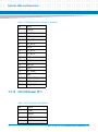
3.2.18 TPM Header (P8)
Table 3-19 TPM Header (P8) Pin Definition
Pin
Signal
1
LPC_CLKOUT0
2
GND
3
LPC_FRAME_N
NITX-315/NITX-315-ET Installation and Use (6806800L71D)
51
Controls, LEDs, and Connectors
Table 3-19 TPM Header (P8) Pin Definition (continued)
Pin
Signal
4
Dummy
5
TPM_RST_N
6
D50VS
7
LPC_AD<3>
8
LPC_AD<2>
9
D33VS
10
LPC_AD<1>
11
LPC_AD<0>
12
GND
13
SMB_CLK
14
SMB_DAT
15
D33V
16
LPC_SERIRQ
17
GND
18
TPM_CLKRUN_N
19
TPM_LPCPD_N
20
TPM_LDRQ0_N
3.2.19 CPU FAN Header (P1)
Table 3-20 CPU FAN Header Pin Definition
52
Pin
Signal
1
GND
2
D50VS
3
TACH
4
PWM
NITX-315/NITX-315-ET Installation and Use (6806800L71D)
Controls, LEDs, and Connectors
3.2.20 ATX 4-Pin Power Header (J4)
Table 3-21 ATX 4-Pin Power Header Pin Definition
Pin
Signal
1
GND
2
GND
3
+12V
4
+12V
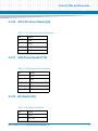
3.2.21 SATA Power Header (P16)
Table 3-22 SATA Power Header Pin Definition
Pin
Signal
1
+12V
2
GND
3
+5V
4
GND
5
+3.3V
3.2.22 I2C Header (P9)
Table 3-23 I2C Header Pin Definition
Pin
Signal
1
+3.3V
2
I2C_CLK
NITX-315/NITX-315-ET Installation and Use (6806800L71D)
53
Controls, LEDs, and Connectors
Table 3-23 I2C Header Pin Definition (continued)
Pin
Signal
3
I2C_DAT
4
GND
3.2.23 J9 SATA Connector
Table 3-24 J9 SATA Pin Definition
54
Pin
Signal
S1
GND
S2
SATA_TXP
S3
SATA_TXN
S4
GND
S5
SATA_RXN
S6
SATA_RXP
S7
GND
P1
+3.3V
P2
+3.3V
P3
+3.3V
P4
GND
P5
GND
P6
GND
P7
+5V
P8
+5V
P9
+5V
P10
GND
P11
RESERVED
P12
GND
NITX-315/NITX-315-ET Installation and Use (6806800L71D)
Controls, LEDs, and Connectors
Table 3-24 J9 SATA Pin Definition (continued)
3.3
Pin
Signal
P13
+12V
P14
+12V
P15
+12V
Onboard LEDs
Table 3-25 Onboard LEDs
Location
Color
Description
D2
RED
Processor Hot Alert
D8
RED
Thermal Trip Alert
D12
Green
Power OK indicator
NITX-315/NITX-315-ET Installation and Use (6806800L71D)
55
Controls, LEDs, and Connectors
56
NITX-315/NITX-315-ET Installation and Use (6806800L71D)
Chapter 4
Functional Description
4.1
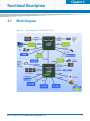
Block Diagram
Figure 4-1
Block Diagram for NITX-315/NITX-315-ET
NITX-315/NITX-315-ET Installation and Use (6806800L71D)
57
Functional Description
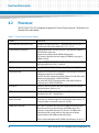
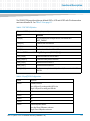
4.2
Processor
NITX-315/NITX-315-ET is designed to support the Tunnel Creek processor. The features are
detailed in the table below:
Table 4-1 Tunnel Creek Processor Features
Feature
Description
Low-Power Intel Architecture Core
600 MHz (Ultra Low Power SKU), 1.0 GHz (Mainstream SKU) and 1.3
GHz(Premium SKU) with related TDP 2.7, 3.1, 3.3 W
System Memory Controller
Single-channel DDR2 memory controller 32-bit data bus Supports
DDR2 800 MT/s data rates.
Supports only soldered-down DRAM configurations.
The memory controller does not support SODIMM or any type of
DIMMs currently.
Video Decode
supports MPEG2, MPEG4, VC1, WMV9, H.264 (main, baseline@L3
and high-profile level 4.0/4.1), and DivX.
Video Encode
supports MPEG4, H.263, H.264 (baseline@L3), and VGA/QGA.
Display Interfaces
supports LVDS and Serial DVO display ports permitting simultaneous
independent operation of two displays
The LVDS interface supports pixel color depths of 18 and 24 bits with
maximum resolution up to 1280x768 @ 60Hz.
The Serial DVO (SDVO) Display Interface can provide maximum
resolution up to 1280x1024 @ 85Hz.
PCI Express
has four x1 lane PCI Express root ports supporting the PCI Express
Base Specification, Revision 1.0a.
LPC Interface
The Tunnel Creek Processor implements an LPC interface as
described in the LPC1.1 Specification.
Intel High Definition Audio (Intel HD
Audio) Controller
The Intel HD Audio controller supports up to four audio streams, two
in and two out. With the support of multi-channel audio stream, 32bit sample depth, and sample rate up to 192 kHz.
SMBus Host Controller
The Tunnel Creek Processor contains an SMBus host interface that
allows the processor to communicate with SMBus slaves. This
interface is compatible with most I2C devices. The SMBus host
controller provides a mechanism for the processor to initiate
communications with SMBus peripherals (slaves).
See the System Management Bus (SMBus) Specification, Version 1.0.
58
NITX-315/NITX-315-ET Installation and Use (6806800L71D)
Functional Description
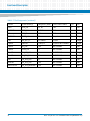
Table 4-1 Tunnel Creek Processor Features (continued)
Feature
Description
General Purpose I/O (GPIO)
The Tunnel Creek Processor contains a total of 14 GPIO pins. Five of
these GPIOs are powered by core power rail and are turned off during
sleep mode (S3 and higher). Nine of these GPIOs are powered by the
suspend power well and remained active during S3. Four of the GPIOs
in suspend power well can be used to wake the system from the
Suspend-to-RAM state. The GPIOs are not 5V tolerant.
Serial Peripheral Interface (SPI)
The Tunnel Creek Processor contains a SPI interface that supports
boot from SPI flash. This interface only supports BIOS boot.
Power Management
The processor contains full support for the Advanced Configuration
and Power Interface (ACPI) Specification, Revision 3.0.
Watchdog Timer (WDT)
The Tunnel Creek Processor supports a user configurable watchdog
timer. It contains selectable prescaler approximately 1 microsecond
to 10 min. When the WDT triggers, GPIO [4] will be asserted.
Package
The Tunnel Creek Processor is a 676 solder balls with 0.8mm ball
pitch FCBGA. The package dimensions are 22mm x 22mm, Z-height
is 2.097mm -2.35mm.
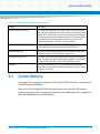
4.3
System Memory
The Tunnel Creek integrated a single channel 32-bit non ECC DDR2 controller, it supports up to
1GB DDR2 memory at 800MHz.
There are 8 1Gb X 8 data width DRAM chips which forms a two Rank total 1GB memory
capacity topology. And for some low-end configuration, the DRAM chips can be configured as
one Rank topology which is a 512MB solution.
NITX-315/NITX-315-ET Installation and Use (6806800L71D)
59
Functional Description
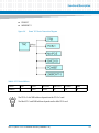
4.4
PCI-E Port
There are a total of four x1 PCI-E Gen1 ports in the TNC. The following figure displays the PCIE ports configuration:
Figure 4-2
4.5
PCI-E Connection Diagram
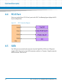
SATA
Two SATA ports are routed to the connector from the Topcliff, the SATA rate is 3Gbps and
supports AHCI. One port is a 7-pin SATA connector, another is a 15-power+7signals connector
which is used for "Slim Lite SSD".
60
NITX-315/NITX-315-ET Installation and Use (6806800L71D)
Functional Description
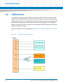
4.6
MicroSD
There are two SDIO links in NITX-315/NITX-315-ET, Link1 is routed to a microSD slot. Link0 is
routed to an inner header, see Table 3-15 on page 49.
Figure 4-3
4.7
SDIO Link Connection Diagram
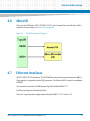
Ethernet Interfaces
NITX-315/NITX-315-ET provides a 10/100/1000 Ethernet connecting to the connector RJ45 J1.
The magnetic is integrated into the RJ45 connector. The Ethernet MAC is stored in an onboard
EEPROM.
The connection interface is RGMII between Topcliff and Marvell 88E1111.
The Ethernet supports LAN wake function.
There are 2 types of power supply required by Marvel 88E1111: 2.5 V and 1.2 V.
NITX-315/NITX-315-ET Installation and Use (6806800L71D)
61
Functional Description
4.8
USB Interface
The Topcliff can support up to six USB2.0 host interfaces and one USB client interface which
complies with USB2.0 and USB1.1 protocols. For the host ports, two ports are routed to the
back IO panel; two ports are routed to one 2X5 pin inner header; one port is routed to the USB
flash header and the last one is routed to a switch which can lead the port to the USB flash
header or the mini PCIE slot. The function can be selected in the BIOS setup menu. The client
USB port is routed to a header.
The Following figure is the routing diagram. SeeTable 3-8 on page 45 and Table 3-9 on page
46.
Figure 4-4
62
USB ports connections diagram
NITX-315/NITX-315-ET Installation and Use (6806800L71D)
Functional Description
4.9
USB Flash
The on-board standard profile USB Flash (SSD) header supports the USB flash module which
stores the OS and application software allowing for boot up without a hard disk drive.
USB port 4 is used as the interface. The USB flash uses a 2x5 header with pitch 2.54 mm, the
header signal definition is displayed in the figure below:
Figure 4-5
4.10
USB Flash Connector Pin Definition
RS-232
There are four UART ports integrated in the Topcliff, one is a full 9-pin RS232 connecting to a
COM header P7. The others are 3-pin RS232 connecting to CH7317A-BF. See Table 3-13 on
page 48 and Table 3-14 on page 49.
4.11
CAN bus
A CAN bus integrated in the Topcliff, The features are:
Supports CAN Protocol Version 2.0B Active
Supports bit rate up to 1 Mbit/s
Supports 32 message objects
Each message object has its own mask (identifier/direction/extended/New Data)
NITX-315/NITX-315-ET Installation and Use (6806800L71D)
63
Functional Description
Priority control by each message object
Programmable FIFO mode (concatenation of message objects)
Maskable interrupt (bus-off/error warning/reception completion/transmission
completion)
Detection/identification of bit error/stuff error/CRC error/form error/acknowledge error
Programmable loop-back mode for self-test operation
DAR (Disabled Automatic Retransmission) mode for time triggered CAN applications
See Table 3-11 on page 47.
4.12
I2C Serial Interface and Devices
There is one I2C compatible SMbus on the TNC. The following devices connect to the SMbus:
64
TPM
One 1x PCI-E slot
One Mini PCI-E slot
Temperature sensor EMC2103
NITX-315/NITX-315-ET Installation and Use (6806800L71D)
Functional Description
PCA9557
LM80CIMT-3
Figure 4-6
Board I2C Device Connection Diagram
Table 4-2 I2C Device Address
Device
Address
TPM
PCIEx1
Mini-PCIE
EMC2103
PCA9557
LM80
Note1
Note2
5C
30
50
The PCI-E x1 slot SMB address depends on the PCI-E x1 card.
The Mini PCI-E card SMB address depends on the Mini PCI-E card
NITX-315/NITX-315-ET Installation and Use (6806800L71D)
65
Functional Description
4.13
Video Interface
TNC supports two types of display output: SDVO and LVDS. For SDVO application, NITX315/NITX-315-ET uses a transfer solution CH7317A-BF to provide the SDVO to VGA usage.
The LVDS interface supports pixel color depths of 18 and 24 bits and a maximum resolution of
up to 1280x768 at 60Hz. Minimum pixel clock is 19.75MHz while the maximum pixel clock rate
is up to 80MHz.
The standard BIOS supports SDVO VGA out and LVDS output.
4.14
Audio Interface
TNC can support a high definition audio interface. An Audio Codec is applied to the HDA link
for NITX-315/NITX-315-ET and one line-in and line-out port jacks are mounted in the back IO
panel. A header P12 for the front panel audio output is provided. See Table 3-10 on page 47.
4.15
TPM Interface
The LPC is routed to a header P8 which is targeted for TPM application.
4.16
BIOS Device
The SPI Flash is used as a BIOS device. The SPI BIOS chip capacity is 4 MB.
NITX-315/NITX-315-ET also provides an SF100 onboard SPI flash program function. When this
feature is used, the input power should be cut fully to avoid damage to the chipset. See Table
3-12 on page 48.
4.17
GPIO Configuration
There are three parts of GPIO in NITX-315/NITX-315-ET, one is a user define GPIO which is
generated from PCA9557PW. The second part GPIO is coming from the TNC and the 3rd part
GPIO is derived from Topcliff.
66
NITX-315/NITX-315-ET Installation and Use (6806800L71D)
Functional Description
The PCA9557PW provides eight user defined GPIOs, 4 GPI and 4 GPO with 5V referenced on
one internal header P4. See Table 3-18 on page 51.
Table 4-3 TNC GPIO Definition
5 Core-well GPIOs (turned off during sleep mode)
Name
Function
GPIO[4]
LPC[0] clock buffer strength control, Also muxed with
WDT_TIMEOUT
GPIO[3:2]
Defines CMC base address
GPIO[1]
Reserved
GPIO[0]
Defines boot flash from SPI or LPC
9 Sus well GPIOs accessible during S3 sleep state (GPIO SUS[0:8])
GPIO_SUS[8]
Defines number of ranks enabled
GPIO_SUS[6:5]
Defines memory device densities
GPIO_SUS[2]
Muxed with LVDS BKLTCTL
GPIO_SUS[1]
Muxed with LVDS BKLTEN
GPIO_SUS[0]
Defines memory device width (x16 or x8) Also muxed with LVDS
VDDEN
Table 4-4 Topcliff GPIO Configuration
Name
Function
GPIO0
USB MUX control.
Low: USB port5 is routing to Mini PCI-E slot
High : USB port5 is routing to eUSB slot
GPIO1
NC
GPIO2
NC
GPIO3
NC
GPIO4
NC
GPIO5
Client USB power detect.
Low: No Client USB power existence
High: Client USB power existence
NITX-315/NITX-315-ET Installation and Use (6806800L71D)
67
Functional Description
Table 4-4 Topcliff GPIO Configuration (continued)
Name
Function
GPIO6
NC
GPIO7
NC
GPIO8
DRAM vendor.
Low: SAMSUNG
High: MICRON
GPIO9
MEM capacity.
Low: 1GB
High: 512MB
GPIO10
MEM freq.
Low: 667MHz
High: 800MHz
GPIO11
68
NC
NITX-315/NITX-315-ET Installation and Use (6806800L71D)
Functional Description
4.18
Clock Distribution
The following figure displays the clock source used by NITX-315/NITX-315-ET:
Figure 4-7
Clock Distribution of NITX-315/NITX-315-ET
Table 4-5 Clock Assignments
DEVICE
CLOCK SIGNAL(S)
FREQUENCY (MHz)
CLOCK TREE SOURCE
QTY
VIO
TNC
BCLK
100
BU7335MWV
1
DIFF
TNC
HPLL_REFCLK
100
BU7335MWV
1
DIFF
TNC
SDVO_REFCLK
96
BU7335MWV
1
DIFF
TNC
CLK_14MHZ
14.318
BU7335MWV
1
Single
TNC
CPU_PCIE_CLK
100
BU7335MWV
1
DIFF
LPC(From TNC)
LPC_CLKOUT0
33
TNC
1
Single
HDACLK
HDA_CLK
24
TNC
1
Single
NITX-315/NITX-315-ET Installation and Use (6806800L71D)
69
Functional Description
Table 4-5 Clock Assignments (continued)
DEVICE
CLOCK SIGNAL(S)
FREQUENCY (MHz)
CLOCK TREE SOURCE
QTY
VIO
LVDS
LVDS_CLK
20~80
TNC
1
DIFF
CH7317B
SDVO_CLK
20~160
TNC
1
DIFF
Memory
DDR_CK
400
TNC
1
DIFF
9LPRS436
CK505_X1
25
Crystal
1
Single
TNC
TNC_RTC_X1
32.768KHz
Crystal
1
Single
Topcliff
UARTCLK
1.8432/12
Crystal or BU7335MWV
1
Single
Topcliff
IOH_CLK
100
BU7335MWV
1
DIFF
Topcliff
SATA0_CLK
75
BU7335MWV
1
DIFF
Topcliff
IOH_USB_CLK
48
BU7335MWV
1
Single
Topcliff
IOH_SYS_CLK
25
BU7335MWV
1
Single
PHY
CLK_PCIE_LAN
25
BU7335MWV
1
DIFF
PCIE slot
CLK_PCIE_SLOT
100
BU7335MWV
1
DIFF
Mini PCIE slot
CLK_PCIE_MINICARD
100
BU7335MWV
1
DIFF
70
NITX-315/NITX-315-ET Installation and Use (6806800L71D)
Chapter 5
BIOS
5.1
POST
After power-up or reset, the BIOS performs a self-test, POST, that attempts to determine if
further operation is possible and that the detected configuration is expected. This process can
complete normally or result in a warning or an error. The boot process does not stop after a
warning but displays a message on the primary display device. If an error is detected, the boot
process is halted. If possible, a message will be displayed but failures early on in the test can
only be indicated in POST codes.
The POST process display depends on the Quiet Boot option.
Viewing all checkpoints generated by Aptio firmware requires a checkpoint card, which is
also named "POST Card" or "POST Diagnostic Card". They are PCI or LPC add-in cards that
show the value of I/O port 80h on a LED display. These cards are available at the electronic
or computer market around the world.
5.2
Boot Process
While performing the functions of the traditional BIOS, Aptio 4.x core follows the firmware
model described by the Intel Platform Innovation Framework for EFI ("the Framework"). The
framework is associated to the following "boot phases", which can be described by various state
code.
5.3
Security (SEC) - initial low-level initialization
Pre-EFI Initialization (PEI) - memory initialization1
Driver Execution Environment (DXE) - main hardware initialization2
Boot Device Selection (BDS) - system setup, pre-OS user interface & selecting a bootable
device (CD/DVD, HDD, USB, Network, Shell, etc.)
Initiating Setup
During the boot, pressing the F2 key on the keyboard requests the Setup utility be launched
once the self-test is complete and before searching for a boot device. See the Setup description
later in this document to describe the operation of this utility. If you exit Setup without saving
any changes, the boot process continues with the search for a boot device. If the changes are
saved, the motherboard loads the new settings and resets - re-starting the entire boot process.
NITX-315/NITX-315-ET Installation and Use (6806800L71D)
71
BIOS
5.4
Setup Utility
The BIOS incorporates a Setup utility that allows the user to alter a variety of system options.
This section describes the operation of the utility by describing the various options available
through a set of hierarchical menus. Not all options are available with all products and some
depend on BIOS customizations.
The current settings are stored in the SPI FLASH NVRAM area and any changes can be copied
back to this area via the Exit menu. The operation of the BIOS defaults is described later in this
document.
To start the utility, you must press the F2 key during the early stages of POST after power-up.
Note that this functionality operates with PS/2 keyboards, USB keyboards when enabled, and
via the console redirection facility when enabled.
The table below briefly describes the primary menus, most of which have sub-menus. The
following sections describe the menus in detail.
Table 5-1 BIOS Primary Menu
72
Menu
Options
Main
BIOS information and date and time
Advanced
Advanced features including ACPI, CPU, IDE, USB, HW monitoring
and Serial Port settings
Chipset
Features including Host Bridge and Southbridge
Boot
Boot mode and Boot options
Security
Administrator's password
Save & Exit
Save with or without changes, Load/save default settings and Boot
Device Selection
NITX-315/NITX-315-ET Installation and Use (6806800L71D)
BIOS
The Aptio navigation can be accomplished using a combination of the keys. These keys include
the <FUNCTION> keys, <ENTER>, <ESC>, <ARROW> keys, and so on.
Table 5-2 Aptio Navigation
Key
Description
ENTER
The Enter key allows the user to select an option to edit its value or
access a sub menu.
Left/Right
The Left and Right <Arrow> keys allow you to select a screen.
Up/Down
The Up and Down <Arrow> keys allow you to select an item or subscreen.
+- Plus/Minus
The Plus and Minus <Arrow> keys allow you to change the field value
of a particular setup item.
Tab
The <Tab> key allows you to select fields.
ESC
The <Esc> key allows you to discard any changes you have made and
exit the Aptio Setup.
When you are in sub-menu, <Esc> allows you to exit to the upper
menu.
Function keys
When other function keys become available, they are displayed at
the right of the screen along with their intended function.
NITX-315/NITX-315-ET Installation and Use (6806800L71D)
73
BIOS
5.4.1
Main Menu
Figure 5-1
Main Menu
Table 5-3 Main Menu Field Description
Field
Description
BIOS Vendor
BIOS vendor name.
Core Version
Aptio core version.
Project Version
Project name and its version.
Build Date
BIOS build date.
Memory Information
74
NITX-315/NITX-315-ET Installation and Use (6806800L71D)
BIOS
Table 5-3 Main Menu Field Description (continued)
Field
Description
MRC Version
Show MRC Information
Total Memory
Show Total Memory Information
Platform Information
System Date
System Time
Sets the time and date (month/day/year format). To change these
values, go to each field and enter the desired value. Press the tab key
to move from hour to minute to second, or from month to day to
year. There is no default value.
Access Level
Show Administrator or User access level
Table 5-4 Platform Information
Field
Description
Tunnel Creek Version
02 (B1 Stepping)
PUNIT Build Date
May 24 2011
PUNIT Build Time
0:38:19
NITX-315/NITX-315-ET Installation and Use (6806800L71D)
75
BIOS
5.4.2
Advanced Menu
Figure 5-2
Advanced Menu
Table 5-5 Advanced Menu Field Description
Field
Description
Launch PXE OpROM
Enable or Disable Boot Option for Legacy Network Devices. Default is
"Enabled".
ACPI Settings
System ACPI Parameters, see Table 5-6 on page 77
Trusted Computing
Trusted Computing (TPM) settings, see Table 5-7 on page 77
CPU Configuration
CPU Configuration Parameters, see Table 5-8 on page 78
Watchdog Timer Configuration
Enable or Disable Watchdog Timer Function (WDT) , see Table 5-9 on
page 79
SDIO Configuration
SDIO configuration Parameters, see Table 5-10 on page 79
76
NITX-315/NITX-315-ET Installation and Use (6806800L71D)
BIOS
Table 5-5 Advanced Menu Field Description (continued)
Field
Description
USB Configuration
USB Configuration Parameters, see Table 5-11 on page 79
LM80 H/W Monitor
Monitor hardware status, see Table 5-12 on page 80
EMC2103 H/W Monitor
Monitor hardware status, see Table 5-13 on page 80
Serial Port Console Redirection
Serial Port Console Redirection, see Table 5-14 on page 80
Table 5-6 ACPI Settings
Field
Description
ACPI Sleep State
Select the highest ACPI sleep state the system will enter, when the
SUSPEND button is pressed. States: Suspend Disabled and S3
(Suspend to RAM). Default is "S3(Suspend to RAM)".
Table 5-7 Trusted Computing
Field
Description
TPM Configuration
TPM SUPPORT
Enables or Disables TPM support. O.S. will not show TPM. Reset of
platform is required. Items: Disable or Enable. The default value is
"Disable".
TPM State
Turn TPM Enable/Disable. NOTE: Your Computer will reboot during
restart in order to change State of TPM. Items: Disabled, Enabled.
Default is "Disabled".
Pending TPM Operation
Schedule TPM operation. NOTE: Your Computer will reboot during
restart in order to change the State of TPM.
Items: None, Enable Take Ownership, Disable Take Ownership, TPM
Clear. Default is "None".
Current TPM Status Information
TPM Enable Status:
If TPM SUPPORT is Disable, the TPM Status information will show as
"TPM Support OFF" or "NO TPM Hardware" based on the TPM
hardware connection status. If TPM SUPPORT is set to "Enable", it will
show the following information
Provides the current TPM Enable/Disable status information. Items:
Disabled, Enabled.
NITX-315/NITX-315-ET Installation and Use (6806800L71D)
77
BIOS
Table 5-7 Trusted Computing (continued)
Field
Description
TPM Active Status:
Provides the current active state of the TPM. Items: Activated,
Deactivated.
TPM Owner Status:
Provides current TPM Ownership state. Items: Owned, UnOwned.
Table 5-8 CPU Configuration
Field
Description
Processor Type Information
Processor Type information
EMT64
EMT64
Processor Speed
Processor Speed
System Bus Speed
System Bus Speed
Ratio Status
Ratio Status
Actual Ratio
Actual Ratio
Processor Stepping
Process Stepping
Microcode Revision
Microcode Revision
L1 Cache RAM
L1 Cache RAM
L2 Cache RAM
L2 Cache RAM
Processor Core
Processor Core
Hyper-Threading
Hyper-Threading
Intel SpeedStep
Enable or Disable Intel® SpeedStep™. Default is Enabled.
Hyper-Threading
Enabled for Windows XP and Linux (OS optimized for HyperThreading technology) and Disabled for other OS (OS not
optimized for Hyper-Threading Technology). Default is "Enabled".
Execute Disable Bit
XD can prevent certain classes of malicious buffer overflow attacks
when combined with a supporting OS (Windows Server 2003 SP1,
Windows XP SP2, SuSE Linux 9.2, RedHat Enterprise 3 Update 3.)
Default is "Enabled".
Intel Virtualization
When enabled, a VM can utilize the additional hardware
capabilities provided by Vanderpool Technology. Default is
"Disabled".
C-States
Enable/Disable C2 and above. Default is "Enabled".
78
NITX-315/NITX-315-ET Installation and Use (6806800L71D)
BIOS
Table 5-8 CPU Configuration (continued) (continued)
Field
Description
Enhanced C3
Enable or Disable Enhanced C3 State. Default is "Disabled".
Table 5-9 Watchdog Timer Configuration
Field
Description
Watchdog Timer
Select an optimal settings Watchdog Timer (WDT). Items:
Disabled, Enabled. Default value is "Disabled".
WDT Reset Type
Select the wanted reset type when the watchdog timer is
triggered. Items: Cold Reset, Warm Reset. Default is "Warm Reset".
Time-Out (Minutes)
Set timer to wait before system reset. The value range is from 1 to
10 minutes, the step is 1 minute. Default value is "5 minutes".
Table 5-10 SDIO Configuration
Field
Description
SDIO Access Mode
Auto Option: Access SD device in DMA mode if controller supports
it, otherwise in PIO mode. DMA Option: Access SD device in DMA
mode. PIO Option: Access SD device in PIO mode.
Default is Auto.
Table 5-11 USB Configuration
Field
Description
USB Devices:
List the attached USB Devices
USB Support
USB Support Parameters.
Legacy USB Support
Enables Legacy USB support. AUTO option disables legacy support
if no USB devices are connected. Disable option will keep USB
devices available only for EFI application. Default is "Enabled".
EHCI Hand-off
This is a workaround for OSes without EHCI hand-off support. The
EHCI ownership change should be claimed by EHCI driver. Default
is "Enabled".
Mass Storage Devices:
List the attached Mass Storage Devices.
NITX-315/NITX-315-ET Installation and Use (6806800L71D)
79
BIOS
Table 5-12 LM80 H/W Monitor
Field
Description
CPU_VCORE
Monitor the CPU VCORE voltage
VCC0_89
Monitor the VCC 0.89V
VCC1_05
Monitor the VCC 1.05V
VCC1_2
Monitor the VCC 1.2V
VCC1_8
Monitor the VCC 1.8V
VCC3_3
Monitor the VCC 3.3V
VCC5
Monitor the VCC 5V
Table 5-13 EMC2103 H/W Monitor
Field
Description
CPU Temperature
CPU Temperature
Board Temperature
Board Temperature
CPU Fan Speed
CPU Fan Speed
CPU Fan Duty Cycle
CPU Fan Duty Cycle
Automatic Fan Control
Enable/Disable automatic fan control in the EMC2103. Default is
"Enabled".
Table 5-14 Serial Port Console Redirection
Field
Description
COM0(Pci Bus2,Dev10,Func1)
Console Redirection
Console Redirection Enable or Disable. Default is Disabled.
Console Redirection Settings
See Table 5-14 on page 80
COM1(Pci Bus 2,Dev 10,Func2)
Console Redirection
Console Redirection Enable or Disable. Default is Disabled.
Console Redirection Settings
See later description
COM2(Pci Bus 2,Dev 10,Func3)
Console Redirection
80
Console Redirection Enable or Disable. Default is Disabled.
NITX-315/NITX-315-ET Installation and Use (6806800L71D)
BIOS
Table 5-14 Serial Port Console Redirection (continued)
Field
Description
Console Redirection Settings
See later description
COM3(Pci Bus 2,Dev 10,Func4)
Console Redirection
Console Redirection Enable or Disable. Default is Disabled.
Console Redirection Settings
See Table 5-14 on page 80
Serial Port for Out-of-Band Management/Windows Emergency Management Services (EMS)
Console Redirection
Console Redirection Enable or Disable. Default is Disabled.
Out-of-Band Mgmt Port
Microsoft Windows Emergency Management Serivces (EMS)
allows for remote management of a Windows Server OS through a
serial port. Items: COM0, COM1, COM2, COM3. Default is
COM0(Pci Bus2, Dev10, Func1)
Data Bits
8
Parity
None
Stop Bits
1
Terminal Type
VT-UTF8 is the preferred terminal type for out-of-band
management. The next best choice is VT100+ and then VT100.
See above, in Console Redirection Settings page, for more Help
with Terminal Type/Emulation. Items: VT100, VT100+, VT-UTF8,
ANSI. Default is VT-UTF8.
Table 5-15 COM0 Console Redirection Settings
Field
Description
COM0 (PCI Bus2,Dev10,Func1)
Console Redirection Settings
Terminal Type
Emulation: ANSI: Extended ASCII char set. VT100: ASCII char set.
VT100+: Extends VT100 to support color, function keys, etc. VTUTF8: Uses UTF8 encoding to map Unicode chars onto 1 or more
bytes. Items: VT100, VT100+, VT-UTF8, ANSI. Default is VT100.
Bits per second
Selects serial port transmission speed. The speed must be
matched on the other side. Long or noisy lines may require lower
speeds. Items: 9600, 19200, 57600, 115200. Default is 115200.
Data Bits
Selects the data bits. Items: 7, 8. Default is 8.
NITX-315/NITX-315-ET Installation and Use (6806800L71D)
81
BIOS
Table 5-15 COM0 Console Redirection Settings (continued)
Field
Description
Parity
A parity bit can be sent with the data bits to detect some
transmission errors. Even: parity bit is 0 if the num of 1's in the data
bits is even. Odd: parity bit is 0 if num of 1's in the data bits is odd.
Mark: parity bit is always 1. Space: Parity bit is always 0. Mark and
Space Parity do not allow for error detection. They can be used as
an additional data bit. Items: None, Even, Odd, Mark, Space.
Default is None.
Stop Bits
Stop bits indicate the end of a serial data packet. (A start bit
indicates the beginning). The standard setting is 1 stop bit.
Communication with slow devices may require more than 1 stop
bit. Items: 1, 2. Default is 1.
Flow Control
Flow control can prevent data loss from buffer overflow. When
sending data, if the receiving buffers are full, a 'stop' signal can be
sent to stop the data flow. Once the buffers are empty, a 'start'
signal can be sent to re-start the flow. Hardware flow control uses
two wires to send start/stop signals. Software flow control uses
start/stop ASCII chars, which slows down the data flow and can be
problematic if binary data is being sent. Items: None, Hardware
RTS/CTS. Default is None.
Recorder Mode
On this mode enabled only text will be send. This is to capture
Terminal data. Items: Disabled, Enabled. Default is Disabled.
Resolution 100x31
Enables or disables extended terminal resolution. Items: Disabled,
Enabled. Default is Enabled.
Legacy OS Redirection
On Legacy OS, the Number of Rows and Columns supported
redirection. Items: 80x24, 80x25. Default is 80x24.
82
NITX-315/NITX-315-ET Installation and Use (6806800L71D)
BIOS
5.4.3
Chipset Menu
Figure 5-3
Chipset Menu
Table 5-16 Chipset Menu Field Descriptions
Field
Description
North Bridge Chipset Configuration
North Bridge Parameters, see Table 5-17 on page 83
South Bridge Chipset Configuration
South Bridge Parameters, see Table 5-19 on page 84
IOH Configuration
IOH Configuration Options
Table 5-17 North Bridge Chipset Configuration
Field
Description
North Bridge Chipset Configuration
NITX-315/NITX-315-ET Installation and Use (6806800L71D)
83
BIOS
Table 5-17 North Bridge Chipset Configuration (continued)
Field
Description
vBIOS Version
2032
IEGD Driver Version
N/A
MSAC Mode Select
Select the size of the graphics memory aperture and untrusted
space. Used by the Integrated Graphics Device. Item: Enabled,
512MB; Enabled, 256MB; Enabled, 128MB. Default is "Enabled,
256MB".
IGD - Boot Type
Select the Video Device which will be activated during POST. This has
no effect if external graphics present. Items: VBIOS Default, CRT,
LVDS, CRT+LVDS. Default is VBIOS Default
Boot Display Configuration
Boot Display Configuration, see Table 5-18 on page 84
This item only shows with LVDS version BIOS, by default, this item is
not shown.
Table 5-18 Boot Display Configuration
Field
Description
Boot Display Configuration
Display Device
Support display device list: VGA CH7317, 800x600 AUO G104SN03,
1024x768 CHI MEI G121X1-L04. The default is the VGA CH7317.
VBIOS supports VESA mode, it could not handle mode 0x123 for display to a non-standard
mode such as 1650x1050.
Table 5-19 South Bridge Chipset Configuration
Field
Description
South Bridge Chipset Configuration
USB MUX Switch
84
Configure the USB MUX setting, switch to Mini-PCIE or USB header.
Items: Mini-PCIE Slot, USB Header. Default is USB Header.
NITX-315/NITX-315-ET Installation and Use (6806800L71D)
BIOS
Table 5-19 South Bridge Chipset Configuration (continued)
Field
Description
PCI Express Ports Configuration
Enable or Disable the PCI Express Ports Chipset, see Table 5-20 on
page 85
Table 5-20 PCI Express Ports Configuration > PCI Express Root Port
Field
Description
Mini PCIE Slot
Enable/Disable the Mini PCIE slot. Default is "Enabled".
Table 5-21 IOH Configuration
Field
Description
Wake On Lan Configuration
Wake On Lan Configuration settings, see later description
Table 5-22 Wake On Lan Configuration
Field
Description
Wake On Lan
Enable/Disable the WOL, Default is Disabled.
WOL Mode
Select WOL Mode. Items: Wake Up Frame, Magic packet. Default is
the Wake Up Frame.
WOL Speed
Select the WOL Speed. Items: 10 Mbps, 100 Mbps, 1000 Mbps.
Default is 10 Mbps.
NITX-315/NITX-315-ET Installation and Use (6806800L71D)
85
BIOS
5.4.4
Boot Menu
Figure 5-4
Boot Menu
Table 5-23 Boot Menu Field Description
86
Field
Description
Quiet Boot
Enables/Disables Quiet Boot option. Default is Enabled.
Setup Prompt Timeout
Number of seconds to wait for setup activation key. 65535(0xffff) means
indefinite waiting. Default value is 1.
Bootup NumLock State
Select the keyboard NumLock state. Items: On, Off. Default is On.
CSM16 Module Version
Display the CSM version
GateA20 Active
UPON REQUEST - GA20 can be disabled using BIOS services. ALWAYS - do
not allow disabling GA20; this option is useful when any RT code is
executed above 1MB. Default is Upon Request.
NITX-315/NITX-315-ET Installation and Use (6806800L71D)
BIOS
Table 5-23 Boot Menu Field Description (continued)
Field
Description
Option ROM Messages
Set display mode for Option ROM. Items: Force BIOS, Keep Current.
Default is Force BIOS.
Interrupt 19 Capture
Enabled: Allows Option ROMs to trap Int 19. Items: Enabled, Disabled.
Default is Disabled.
Boot Option Priorities
Sets the system boot order.
NITX-315/NITX-315-ET Installation and Use (6806800L71D)
87
BIOS
5.4.5
Security Menu
Figure 5-5
Security Menu
Table 5-24 Security Menu Field Description
88
Field
Description
Setup Administrator
Password
Sets the setup administrator password.
User Password
Sets the setup user password.
NITX-315/NITX-315-ET Installation and Use (6806800L71D)
BIOS
5.4.6
Save and Exit Menu
Figure 5-6
Save and Exit Menu
Table 5-25 Save and Exit Menu Field Description
Field
Description
Save Changes and Exit
Exit system setup after saving the changes.
Discard Changes and Exit
Exit system setup without saving any changes.
Save Changes and Reset
Reset the system after saving the changes.
Discard Changes and Reset
Reset system setup without saving any changes.
NITX-315/NITX-315-ET Installation and Use (6806800L71D)
89
BIOS
Table 5-25 Save and Exit Menu Field Description (continued)
Field
Description
Save Changes
Save Changes made so far to any of the setup options.
Discard Changes
Save Changes done so far to any of the setup options.
Restore Defaults
Restore/Load Defaults values for all the setup options.
Save as User Defaults
Save the changes done so far as User Defaults.
Restore User Defaults
Restore the User Defaults to all the setup options.
Boot Override
The options will override the boot orders in 'Boot' menu. So you can freely
select the device which you want to boot.
5.5
POST Codes
5.5.1
Status Code Ranges
Table 5-26 Status Code Ranges
90
Status Code Range
Description
0x01 - 0x0F
SEC Status Codes & Errors
0x10 - 0x2F
PEI execution up to and including memory detection
0x30 - 0x4F
PEI execution after memory detection
0x50 - 0x5F
PEI errors
0x60 - 0xCF
DXE execution up to BDS
0xD0 - 0xDF
DXE errors
0xE0 - 0xE8
S3 Resume (PEI)
0xE9 - 0xEF
S3 Resume errors (PEI)
0xF0 - 0xF8
Recovery (PEI)
NITX-315/NITX-315-ET Installation and Use (6806800L71D)
BIOS
Table 5-26 Status Code Ranges (continued)
Status Code Range
Description
0xF9 - 0xFF
Recovery errors (PEI)
5.5.2
Standard Status Codes
5.5.2.1
SEC Status Codes
Table 5-27 SEC Status Codes
Status Code
Description
0x0
Not used
Progress Codes
0x1
Power on. Reset type detection (soft/hard).
0x2
AP initialization before microcode loading
0x3
North Bridge initialization before microcode loading
0x4
South Bridge initialization before microcode loading
0x5
OEM initialization before microcode loading
0x6
Microcode loading
0x7
AP initialization after microcode loading
0x8
North Bridge initialization after microcode loading
0x9
South Bridge initialization after microcode loading
0xA
OEM initialization after microcode loading
0xB
Cache initialization
SEC Error Codes
0xC - 0xD
Reserved for future AMI SEC error codes
0xE
Microcode not found
0xF
Microcode not loaded
NITX-315/NITX-315-ET Installation and Use (6806800L71D)
91
BIOS
5.5.2.2
PEI Status Codes
Table 5-28 PEI Status Codes
Status Code
Description
Progress Codes
92
0x10
PEI Core is started
0x11
Pre-memory CPU initialization is started
0x12
CPU pre-memory initialization (CPU module specific)
0x13
CPU pre-memory initialization (CPU module specific)
0x14
CPU pre-memory initialization (CPU module specific)
0x15
Pre-memory North Bridge initialization is started
0x16
Pre-Memory North Bridge initialization (North Bridge module
specific)
0x17
Pre-Memory North Bridge initialization (North Bridge module
specific)
0x18
Pre-Memory North Bridge initialization (North Bridge module
specific)
0x19
Pre-memory South Bridge initialization is started
0x1A
Pre-memory South Bridge initialization (South Bridge module
specific)
0x1B
Pre-memory South Bridge initialization (South Bridge module
specific)
0x1C
Pre-memory South Bridge initialization (South Bridge module
specific)
0x1D - 0x2A
OEM pre-memory initialization codes
0x2B
Memory initialization. Serial Presence Detect (SPD) data reading
0x2C
Memory initialization. Memory presence detection
0x2D
Memory initialization. Programming memory timing
information
0x2E
Memory initialization. Configuring memory
0x2F
Memory initialization (other).
NITX-315/NITX-315-ET Installation and Use (6806800L71D)
BIOS
Table 5-28 PEI Status Codes (continued)
Status Code
Description
0x30
Reserved for ASL (see ASL Status Codes section below)
0x31
Memory Installed
0x32
CPU post-memory initialization is started
0x33
CPU post-memory initialization. Cache initialization
0x34
CPU post-memory initialization. Application Processor(s) (AP)
initialization
0x35
CPU post-memory initialization. Boot Strap Processor (BSP)
selection
0x36
CPU post-memory initialization. System Management Mode
(SMM) initialization
0x37
Post-Memory North Bridge initialization is started
0x38
Post-Memory North Bridge initialization (North Bridge module
specific)
0x39
Post-Memory North Bridge initialization (North Bridge module
specific)
0x3A
Post-Memory North Bridge initialization (North Bridge module
specific)
0x3B
Post-Memory South Bridge initialization is started
0x3C
Post-Memory South Bridge initialization (South Bridge module
specific)
0x3D
Post-Memory South Bridge initialization (South Bridge module
specific)
0x3E
Post-Memory South Bridge initialization (South Bridge module
specific)
0x3F-0x4E
OEM post memory initialization codes
0x4F
DXE IPL is started
PEI Error Codes
0x50
Memory initialization error. Invalid memory type or incompatible
memory speed
0x51
Memory initialization error. SPD reading has failed
NITX-315/NITX-315-ET Installation and Use (6806800L71D)
93
BIOS
Table 5-28 PEI Status Codes (continued)
Status Code
Description
0x52
Memory initialization error. Invalid memory size or memory
modules do not match.
0x53
Memory initialization error. No usable memory detected
0x54
Unspecified memory initialization error.
0x55
Memory not installed
0x56
Invalid CPU type or Speed
0x57
CPU mismatch
0x58
CPU self test failed or possible CPU cache error
0x59
CPU micro-code is not found or micro-code update is failed
0x5A
Internal CPU error
0x5B
reset PPI is not available
0x5C-0x5F
Reserved for future AMI error codes
S3 Resume Progress Codes
0xE0
S3 Resume is stared (S3 Resume PPI is called by the DXE IPL)
0xE1
S3 Boot Script execution
0xE2
Video repost
0xE3
OS S3 wake vector call
0xE4-0xE7
Reserved for future AMI progress codes
0xE0
S3 Resume is stared (S3 Resume PPI is called by the DXE IPL)
S3 Resume Error Codes
0xE8
S3 Resume Failed in PEI
0xE9
S3 Resume PPI not Found
0xEA
S3 Resume Boot Script Error
0xEB
S3 OS Wake Error
0xEC-0xEF
Reserved for future AMI error codes
Recovery Progress Codes
0xF0
94
Recovery condition triggered by firmware (Auto recovery)
NITX-315/NITX-315-ET Installation and Use (6806800L71D)
BIOS
Table 5-28 PEI Status Codes (continued)
Status Code
Description
0xF1
Recovery condition triggered by user (Forced recovery)
0xF2
Recovery process started
0xF3
Recovery firmware image is found
0xF4
Recovery firmware image is loaded
0xF5 - 0xF7
Reserved for future AMI progress codes
Recovery Error Codes
5.5.2.3
0xF8
Recovery PPI is not available
0xF9
Recovery capsule is not found
0xFA
Invalid recovery capsule
0xFB - 0xFF
Reserved for future AMI error codes
PEI Beep Codes
Table 5-29 PEI Beep Codes
# of Beeps
Description
1
Memory not Installed
1
Memory was installed twice (InstallPeiMemory routine in PEI
Core called twice)
3
DXEIPL was not found
3
DXE Core Firmware Volume was not found
7
Reset PPI is not available
4
Recovery failed
4
S3 Resume failed
NITX-315/NITX-315-ET Installation and Use (6806800L71D)
95
BIOS
5.5.2.4
DXE Status Codes
Table 5-30 DXE Status Codes
96
Status Code
Description
0x60
DXE Core is started
0x61
NVRAM initialization
0x62
Installation of the South Bridge Runtime Services
0x63
CPU DXE initialization is started
0x64
CPU DXE initialization (CPU module specific)
0x65
CPU DXE initialization (CPU module specific)
0x66
CPU DXE initialization (CPU module specific)
0x67
CPU DXE initialization (CPU module specific)
0x68
PCI host bridge initialization
0x69
North Bridge DXE initialization is started
0x6A
North Bridge DXE SMM initialization is started
0x6B
North Bridge DXE initialization (North Bridge module specific)
0x6C
North Bridge DXE initialization (North Bridge module specific)
0x6D
North Bridge DXE initialization (North Bridge module specific)
0x6E
North Bridge DXE initialization (North Bridge module specific)
0x6F
North Bridge DXE initialization (North Bridge module specific)
0x70
South Bridge DXE initialization is started
0x71
South Bridge DXE SMM initialization is started
0x72
South Bridge devices initialization
0x73
South Bridge DXE Initialization (South Bridge module specific)
0x74
South Bridge DXE Initialization (South Bridge module specific)
0x75
South Bridge DXE Initialization (South Bridge module specific)
0x76
South Bridge DXE Initialization (South Bridge module specific)
0x77
South Bridge DXE Initialization (South Bridge module specific)
NITX-315/NITX-315-ET Installation and Use (6806800L71D)
BIOS
Table 5-30 DXE Status Codes (continued)
Status Code
Description
0x78
ACPI module initialization
0x79
CSM initialization
0x7A
Reserved for future AMI DXE codes
0x80
OEM DXE initialization codes
0x90
Boot Device Selection (BDS) phase is started
0x91
Driver connecting is started
0x92
PCI Bus initialization is started
0x93
PCI Bus Hot Plug Controller Initialization
0x94
PCI Bus Enumeration
0x95
PCI Bus Request Resources
0x96
PCI Bus Assign Resources
0x97
Console Output devices connect
0x98
Console input devices connect
0x99
Super IO Initialization
0x9A
USB initialization is started
0x9B
USB Reset
0x9C
USB Detect
0x9D
USB Enable
0x9E - 0x9F
Reserved for future AMI codes
0xA0
Reserved for ASL (see ASL Status Codes section below)
0xA1
IDE initialization is started
0xA2
IDE Reset
0xA3
IDE Detect
0xA4
IDE Enable
0xA5
SCSI initialization is started
0xA6
SCSI Reset
0xA7
SCSI Detect
NITX-315/NITX-315-ET Installation and Use (6806800L71D)
97
BIOS
Table 5-30 DXE Status Codes (continued)
Status Code
Description
0xA8
SCSI Enable
0xA9
Setup Verifying Password
0xAA
Reserved for ASL (see ASL Status Codes section below)
0xAB
Start of Setup
0xAC
Setup Input Wait
0xAD
Ready To Boot event
0xAE
Legacy Boot event
0xAF
Exit Boot Services event
0xB0
Runtime Set Virtual Address MAP Begin
0xB1
Runtime Set Virtual Address MAP End
0xB2
Legacy Option ROM Initialization
0xB3
System Reset
0xB4
USB hot plug
0xB5
PCI bus hot plug
0xB6
Clean-up of NVRAM
0xB7
Configuration Reset (reset of NVRAM settings)
0xB8
Reserved for future AMI codes
0xC0
OEM BDS initialization codes
DXE Error Codes
98
0xD0
CPU initialization error
0xD1
North Bridge initialization error
0xD2
South Bridge initialization error
0xD3
Some of the Architectural Protocols are not available
0xD4
PCI resource allocation error. Out of Resources
0xD5
No Space for Legacy Option ROM
0xD6
No Console Output Devices are found
0xD7
No Console Input Devices are found
NITX-315/NITX-315-ET Installation and Use (6806800L71D)
BIOS
Table 5-30 DXE Status Codes (continued)
5.5.2.5
Status Code
Description
0xD8
Invalid password
0xD9
Error loading Boot Option (LoadImage returned error)
0xDA
Boot Option is failed (StartImage returned error)
0xDB
Flash update is failed
0xDC
Reset protocol is not available
DXE Beep Codes
Table 5-31 DXE Beep Codes
5.5.2.6
# of Beeps
Description
4
Some of the Architectural Protocols are not available
5
No Console Output Devices are found
5
No Console Input Devices are found
1
Invalid password
6
Flash update is failed
7
Reset protocol is not available
CPU Exception Status Codess
Table 5-32 CPU Exception Status Codes
Status Code
Description
0x00
Divide error
0x01
CPU Debug exception
0x02
Non maskable hardware Interrupt occurred
0x03
INT 3 breakpoint
NITX-315/NITX-315-ET Installation and Use (6806800L71D)
99
BIOS
Table 5-32 CPU Exception Status Codes (continued)
5.5.2.7
Status Code
Description
0x04
Overflow, INT 0 instruction
0x05
Bound Range Exceeded
0x06
Invalid Opcode (undefined Opcode)
0x07
Device Not Available ( No Math Co-Processor)
0x08
Double Fault. Any instruction to the CPU that can Generate an
NMI or INTR
0x09
Co-Processor Segment Overrun
0x0A
Invalid Task Switch Access
0x0B
Segment not present. Occurs after a load segment
0x0C
Stack Segment Fault. Relations to Stack operations
0x0D
General Protection fault. Any memory reference and other
protection checks
0x0E
Page Fault.
0x0F
Reserved by Intel
0x10
Floating Point Error
0x11
Alignment Check
0x12
Machine Check
0x13
SIMD Floating point exception
ASL Status Codes
Table 5-33 ASL Status Codes
100
Status Code
Description
0x01
System is entering S1 sleep state
0x02
System is entering S2 sleep state
0x03
System is entering S3 sleep state
0x04
System is entering S4 sleep state
NITX-315/NITX-315-ET Installation and Use (6806800L71D)
BIOS
Table 5-33 ASL Status Codes (continued)
5.5.2.8
Status Code
Description
0x05
System is entering S5 sleep state
0x10
System is waking up from the S1 sleep state
0x20
System is waking up from the S2 sleep state
0x30
System is waking up from the S3 sleep state
0x40
System is waking up from the S4 sleep state
0xAC
System has transitioned into ACPI mode. Interrupt controller is
in PIC mode.
0xAA
System has transitioned into ACPI mode. Interrupt controller is
in APIC
OEM-reserved Status Code Ranges
Table 5-34 OEM-reserved Status Code Ranges
5.6
Status Code
Description
0x5
OEM SEC initialization before microcode loading
0xA
OEM SEC initialization after microcode loading
0x1D - 0x2A
OEM pre-memory initialization codes
0x3F - 0x4E
OEM PEI post memory initialization codes
0x80 - 0x8F
OEM DXE initialization codes
0xC0 - 0xCF
OEM BDS initialization codes
Boot Order Support
The boot firmware shall be capable of booting an image from eUSB flash, MicroSD and SATAattached hard disk.
NITX-315/NITX-315-ET Installation and Use (6806800L71D)
101
BIOS
5.7
Windows XP Installation
Because the Topcliff only supports the AHCI mode, the AHCI driver must be loaded from the
USB floppy when installing Windows XP. To do this, follow the steps below:
1. Use a USB floppy drive that is included in the Txtsetup.sif file and one that is
supported for use with Windows XP installation. Please refer to this link for more
information: http://support.microsoft.com/kb/916196/en-us
2. Copy the AHCI driver from the CD driver.
3. Unzip the topcliff driver.
4. Open the folder named FD_Inst_WinXP, then copy the following files to the USB
floppy disk: iohsata.cat, iohsata.inf, iohsata.sys, and txtsetup.oem.
5. Connect the USB floppy disk driver and install Windows XP.
6. Press the F6 key upon installing Windows XP.
7. Confirm the IOH AHCI driver.
8. Proceed to the installation of Windows XP.
5.8
Graphic Driver
This graphic driver is built by Intel EMGD. It is not the generic driver. VGA output driver is
provided. For a dual display setup (VGA+LVDS or DVI+LVDS) or a specific LVDS setup, a
customized driver built by the EMGD tool is needed.
5.9
BIOS Update
To update the BIOS, follow the steps listed below:
1. Prepare a dos bootable USB thumb drive.
2. Get the BIOS flash tool (AFUDOS) from the BIOS vendor.
3. Copy the AFUDOS and BIOS ROM file into the USB thumb drive.
102
NITX-315/NITX-315-ET Installation and Use (6806800L71D)
BIOS
4. Power on the Nith board.
5. Press F2 to enter the BIOS setup menu.
6. Select the USB thumb drive as the first boot device.
7. Save and reset, then the board will boot from the USB thumb drive.
8. Run the command AFUDOS BIOS.ROM /P /B /N /R to flash the BIOS.
NITX-315/NITX-315-ET Installation and Use (6806800L71D)
103
BIOS
104
NITX-315/NITX-315-ET Installation and Use (6806800L71D)
Chapter 6
Operating System and Driver Support
6.1
Supported Operating Systems
This module supports the following operating systems:
Microsoft Window XP Professional
Microsoft Window 7
Microsoft Windows Embedded Standard 2007
MeeGo Linux
NITX-315/NITX-315-ET Installation and Use (6806800L71D)
105
Operating System and Driver Support
106
NITX-315/NITX-315-ET Installation and Use (6806800L71D)
Appendix A
A
Replacing the Battery
A.1
Replacing the Battery
The battery location is shown in the following figure.
Figure A-1
Battery Location
NITX-315/NITX-315-ET Installation and Use (6806800L71D)
107
Replacing the Battery
The battery provides data retention of seven years summing up all periods of actual data use.
Artesyn Embedded Technologies therefore assumes that there usually is no need to exchange
the battery except, for example, in case of long-term spare part handling.
Board/System Damage
Incorrect exchange of lithium batteries can result in a hazardous explosion.
When exchanging the onboard lithium battery, make sure that the new and the old
battery are exactly the same battery models.
If the respective battery model is not available, contact your local Artesyn sales
representative for the availability of alternative, officially approved battery models.
Data Loss
Exchanging the battery can result in loss of time settings. Backup power prevents the loss of
data during exchange.
Quickly replacing the battery may save time settings.
Data Loss
If the battery has low or insufficient power the RTC is initialized.
Exchange the battery before seven years of actual battery use have elapsed.
PCB and Battery Holder Damage
Removing the battery with a screw driver may damage the PCB or the battery holder. To prevent
damage, do not use a screw driver to remove the battery from its holder.
Exchange Procedure
To exchange the battery, proceed as follows:
1. Remove the old battery from the battery header.
2. Install the new battery on the battery header.
3. Dispose of the old battery in accordance with local laws on environmental safety.
108
NITX-315/NITX-315-ET Installation and Use (6806800L71D)
Appendix B
B
Related Documentation
B.1
Artesyn Embedded Technologies - Embedded
Computing Documentation
The publications listed below are referenced in this manual. You can obtain electronic copies of
Artesyn Embedded Technologies - Embedded Computing publications by contacting your
local Artesyn sales office. For released products, you can also visit our Web site for the latest
copies of our product documentation.
1. Go to www.artesyn.com/computing.
2. Under SUPPORT, click TECHNICAL DOCUMENTATION.
3. Under FILTER OPTIONS, click the Document types drop-down list box to select the type of
document you are looking for.
4. In the Search text box, type the product name and click GO.
Table B-1 Artesyn Embedded Technologies - Embedded Computing Publications
Document Title
Publication Number
NITX-315/NITX-315-ET Quick Start Guide
6806800L97
NITX-315/NITX-315-ET Safety Notes Summary
6806800L96
NITX-315/NITX-315-ET Installation and Use (6806800L71D)
109
Related Documentation
110
NITX-315/NITX-315-ET Installation and Use (6806800L71D)
Safety Notes
This section provides warnings that precede potentially dangerous procedures throughout
this manual. Instructions contained in the warnings must be followed during all phases of
operation, service, and repair of this equipment. You should also employ all other safety
precautions necessary for the operation of the equipment in your operating environment.
Failure to comply with these precautions or with specific warnings elsewhere in this manual
could result in personal injury or damage to the equipment.
Artesyn intends to provide all necessary information to install and handle the product in this
manual. Because of the complexity of this product and its various uses, we do not guarantee
that the given information is complete. If you need additional information, ask your Artesyn
representative.
The product has been designed to meet the standard industrial safety requirements. It must
not be used except in its specific area of office telecommunication industry and industrial
control.
Only personnel trained by Artesyn or persons qualified in electronics or electrical engineering
are authorized to install, remove or maintain the product.
The information given in this manual is meant to complete the knowledge of a specialist and
must not be used as replacement for qualified personnel.
Keep away from live circuits inside the equipment. Operating personnel must not remove
equipment covers. Only Factory Authorized Service Personnel or other qualified service
personnel may remove equipment covers for internal subassembly or component replacement
or any internal adjustment.
Do not install substitute parts or perform any unauthorized modification of the equipment or
the warranty may be voided. Contact your local Artesyn representative for service and repair
to make sure that all safety features are maintained.
EMC
This equipment has been tested and found to comply with the limits for a Class B digital device,
pursuant to Part 15 of the FCC Rules. These limits are designed to provide reasonable
protection against harmful interference when the equipment is operated in a commercial
environment. This equipment generates, uses, and can radiate radio frequency energy and, if
not installed and used in accordance with the instruction manual, may cause harmful
interference to radio communications.
NITX-315/NITX-315-ET Installation and Use (6806800L71D)
111
Safety Notes
Operation of this equipment in a residential area is likely to cause harmful interference in which
case the user will be required to correct the interference at his own expense. Changes or
modifications not expressly approved by Artesyn Embedded Technologies could void the
user's authority to operate the equipment. Board products are tested in a representative
system to show compliance with the above mentioned requirements. A proper installation in
a compliant system will maintain the required performance. Use only shielded cables when
connecting peripherals to assure that appropriate radio frequency emissions compliance is
maintained.
Operation
Product Damage
High humidity and condensation on the board surface causes short circuits.
Do not operate the board outside the specified environmental limits.
Make sure the board is completely dry and there is no moisture on any surface before applying
power.
Damage of Circuits
Electrostatic discharge and incorrect installation and removal can damage circuits or shorten
their life.
Before touching the board or electronic components, make sure that you are working in an
ESD-safe environment.
Board Malfunction
Switches marked as “reserved” might carry production-related functions and can cause the
board to malfunction if their setting is changed.
Do not change settings of switches marked as “reserved”. The setting of switches which are
not marked as “reserved” has to be checked and changed before board installation.
Installation
Data Loss
Powering down or removing a board before the operating system or other software running
on the board has been properly shut down may cause corruption of data or file systems.
112
NITX-315/NITX-315-ET Installation and Use (6806800L71D)
Safety Notes
Make sure all software is completely shut down before removing power from the board or
removing the board from the chassis.
Product Damage
Only use injector handles for board insertion to avoid damage to the front panel and/or PCB.
Deformation of the front panel can cause an electrical short or other board malfunction.
Product Damage
Inserting or removing modules with power applied may result in damage to module
components.
Before installing or removing additional devices or modules, read the documentation that
came with the product.
Cabling and Connectors
Product Damage
RJ-45 connectors on modules are either twisted-pair Ethernet (TPE) or E1/T1/J1 network
interfaces. Connecting an E1/T1/J1 line to an Ethernet connector may damage your system.
Make sure that TPE connectors near your working area are clearly marked as network
connectors.
Verify that the length of an electric cable connected to a TPE bushing does not exceed 100
meters.
Make sure the TPE bushing of the system is connected only to safety extra low voltage
circuits (SELV circuits).
If in doubt, ask your system administrator.
NITX-315/NITX-315-ET Installation and Use (6806800L71D)
113
Safety Notes
Battery
Board/System Damage
Incorrect exchange of lithium batteries can result in a hazardous explosion.
When exchanging the onboard lithium battery, make sure that the new and the old
battery are exactly the same battery models.
If the respective battery model is not available, contact your local Artesyn sales
representative for the availability of alternative, officially approved battery models.
Data Loss
Exchanging the battery can result in loss of time settings. Backup power prevents the loss of
data during exchange.
Quickly replacing the battery may save time settings.
Data Loss
If the battery has low or insufficient power the RTC is initialized.
Exchange the battery before seven years of actual battery use have elapsed.
PCB and Battery Holder Damage
Removing the battery with a screw driver may damage the PCB or the battery holder. To
prevent damage, do not use a screw driver to remove the battery from its holder.
114
NITX-315/NITX-315-ET Installation and Use (6806800L71D)
Sicherheitshinweise
Dieses Kapitel enthält Hinweise, die potentiell gefährlichen Prozeduren innerhalb dieses
Handbuchs vorrangestellt sind. Beachten Sie unbedingt in allen Phasen des Betriebs, der
Wartung und der Reparatur des Systems die Anweisungen, die diesen Hinweisen enthalten
sind. Sie sollten außerdem alle anderen Vorsichtsmaßnahmen treffen, die für den Betrieb des
Produktes innerhalb Ihrer Betriebsumgebung notwendig sind. Wenn Sie diese
Vorsichtsmaßnahmen oder Sicherheitshinweise, die an anderer Stelle diese Handbuchs
enthalten sind, nicht beachten, kann das Verletzungen oder Schäden am Produkt zur Folge
haben.
Artesyn Embedded Technologies ist darauf bedacht, alle notwendigen Informationen zum
Einbau und zum Umgang mit dem Produkt in diesem Handbuch bereit zu stellen. Da es sich
jedoch um ein komplexes Produkt mit vielfältigen Einsatzmöglichkeiten handelt, können wir
die Vollständigkeit der im Handbuch enthaltenen Informationen nicht garantieren. Falls Sie
weitere Informationen benötigen sollten, wenden Sie sich bitte an die für Sie zuständige
Geschäftsstelle von Artesyn Embedded Technologies.
Das System erfüllt die für die Industrie geforderten Sicherheitsvorschriften und darf
ausschließlich für Anwendungen in der Telekommunikationsindustrie und im Zusammenhang
mit Industriesteuerungen verwendet werden.
Einbau, Wartung und Betrieb dürfen nur von durch Artesyn Embedded Technologies
ausgebildetem oder im Bereich Elektronik oder Elektrotechnik qualifiziertem Personal
durchgeführt werden. Die in diesem Handbuch enthaltenen Informationen dienen
ausschließlich dazu, das Wissen von Fachpersonal zu ergänzen, können dieses jedoch nicht
ersetzen.
Halten Sie sich von stromführenden Leitungen innerhalb des Produktes fern. Entfernen Sie auf
keinen Fall Abdeckungen am Produkt. Nur werksseitig zugelassenes Wartungspersonal oder
anderweitig qualifiziertes Wartungspersonal darf Abdeckungen entfernen, um Komponenten
zu ersetzen oder andere Anpassungen vorzunehmen.
Installieren Sie keine Ersatzteile oder führen Sie keine unerlaubten Veränderungen am Produkt
durch, sonst verfällt die Garantie. Wenden Sie sich für Wartung oder Reparatur bitte an die für
Sie zuständige Geschäftsstelle von Artesyn Embedded Technologies. So stellen Sie sicher, dass
alle sicherheitsrelevanten Aspekte beachtet werden.
NITX-315/NITX-315-ET Installation and Use (6806800L71D)
115
Sicherheitshinweise
EMV
Das Produkt wurde in einem Artesyn Standardsystem getestet. Es erfüllt die für digitale Geräte
der Klasse B gültigen Grenzwerte in einem solchen System gemäß den FCC-Richtlinien
Abschnitt 15 bzw. EN 55022 Klasse B. Diese Grenzwerte sollen einen angemessenen Schutz vor
Störstrahlung beim Betrieb des Produktes in Gewerbe- sowie Industriegebieten
gewährleisten.
Das Produkt arbeitet im Hochfrequenzbereich und erzeugt Störstrahlung. Bei
unsachgemäßem Einbau und anderem als in diesem Handbuch beschriebenen Betrieb können
Störungen im Hochfrequenzbereich auftreten.
Wird das Produkt in einem Wohngebiet betrieben, so kann dies mit grosser Wahrscheinlichkeit
zu starken Störungen führen, welche dann auf Kosten des Produktanwenders beseitigt werden
müssen. Änderungen oder Modifikationen am Produkt, welche ohne ausdrückliche
Genehmigung von Artesyn Embedded Technologiesdurchgeführt werden, können dazu
führen, dass der Anwender die Genehmigung zum Betrieb des Produktes verliert.
Boardprodukte werden in einem repräsentativen System getestet, um zu zeigen, dass das
Board den oben aufgeführten EMV-Richtlinien entspricht. Eine ordnungsgemässe Installation
in einem System, welches die EMV-Richtlinien erfüllt, stellt sicher, dass das Produkt gemäss
den EMV-Richtlinien betrieben wird. Verwenden Sie nur abgeschirmte Kabel zum Anschluss
von Zusatzmodulen. So ist sichergestellt, dass sich die Aussendung von
Hochfrequenzstrahlung im Rahmen der erlaubten Grenzwerte bewegt.
Warnung! Dies ist eine Einrichtung der Klasse A. Diese Einrichtung kann im Wohnbereich
Funkstörungen verursachen. In diesem Fall kann vom Betreiber verlangt werden,
angemessene Maßnahmen durchzuführen.
Betrieb
1 Beschädigung des Produktes
Hohe Luftfeuchtigkeit und Kondensat auf der Oberfläche des Produktes können zu
Kurzschlüssen führen.
Betreiben Sie das Produkt nur innerhalb der angegebenen Grenzwerte für die relative
Luftfeuchtigkeit und Temperatur. Stellen Sie vor dem Einschalten des Stroms sicher, dass sich
auf dem Produkt kein Kondensat befindet.
116
NITX-315/NITX-315-ET Installation and Use (6806800L71D)
Sicherheitshinweise
Beschädigung von Schaltkreisen
Elektrostatische Entladung und unsachgemäßer Ein- und Ausbau des Produktes kann
Schaltkreise beschädigen oder ihre Lebensdauer verkürzen.
Bevor Sie das Produkt oder elektronische Komponenten berühren, vergewissern Sie
sich, daß Sie in einem ESD-geschützten Bereich arbeiten.
Fehlfunktion des Produktes
Schalter, die mit 'Reserved' gekennzeichnet sind, können mit produktionsrelevanten
Funktionen belegt sein. Das Ändern dieser Schalter kann im normalen Betrieb Störungen
auslösen.
Verstellen Sie nur solche Schalter, die nicht mit 'Reserved' gekennzeichnet sind.
Prüfen und ggf. ändern Sie die Einstellungen der nicht mit 'Reserved'
gekennzeichneten Schalter, bevor Sie das Produkt installieren.
Installation
Datenverlust
Das Herunterfahren oder die Deinstallation eines Boards bevor das Betriebssystem oder
andere auf dem Board laufende Software ordnungsmemäss beendet wurde, kann zu
partiellem Datenverlust sowie zu Schäden am Filesystem führen.
Stellen Sie sicher, dass sämtliche Software auf dem Board ordnungsgemäss beendet wurde,
bevor Sie das Board herunterfahren oder das Board aus dem Chassis entfernen.
Beschädigung des Produktes
Fehlerhafte Installation des Produktes kann zu einer Beschädigung des Produktes führen.
Verwenden Sie die Handles, um das Produkt zu installieren/deinstallieren. Auf diese Weise
vermeiden Sie, dass das Face Plate oder die Platine deformiert oder zerstört wird.
Beschädigung des Produktes und von Zusatzmodulen
Fehlerhafte Installation von Zusatzmodulen, kann zur Beschädigung des Produktes und der
Zusatzmodule führen.
Lesen Sie daher vor der Installation von Zusatzmodulen die zugehörige Dokumentation.
NITX-315/NITX-315-ET Installation and Use (6806800L71D)
117
Sicherheitshinweise
Kabel und Stecker
Beschädigung des Produktes
Bei den RJ-45-Steckern, die sich an dem Produkt befinden, handelt es sich entweder um
Twisted-Pair-Ethernet (TPE) oder um E1/T1/J1-Stecker. Beachten Sie, dass ein versehentliches
Anschließen einer E1/T1/J1-Leitung an einen TPE-Stecker das Produkt zerstören kann.
Kennzeichnen Sie deshalb TPE-Anschlüsse in der Nähe Ihres Arbeitsplatzes deutlich als
Netzwerkanschlüsse.
Stellen Sie sicher, dass die Länge eines mit Ihrem Produkt verbundenen TPE-Kabels 100 m
nicht überschreitet.
Das Produkt darf über die TPE-Stecker nur mit einem Sicherheits-KleinspannungsStromkreis (SELV) verbunden werden.
Bei Fragen wenden Sie sich an Ihren Systemverwalter.
Batterie
Beschädigung des Blades
Ein unsachgemäßer Einbau der Batterie kann gefährliche Explosionen und
Beschädigungen des Blades zur Folge haben.
Verwenden Sie deshalb nur den Batterietyp, der auch bereits eingesetzt wurde und
befolgen Sie die Installationsanleitung.
Datenverlust
Wenn Sie die Batterie austauschen, können die Zeiteinstellungen verloren gehen. Eine
Backupversorgung verhindert den Datenverlust während des Austauschs.
Wenn Sie die Batterie schnell austauschen, bleiben die Zeiteinstellungen möglicherweise
erhalten.
118
NITX-315/NITX-315-ET Installation and Use (6806800L71D)
Sicherheitshinweise
Datenverlust
Wenn die Batterie wenig oder unzureichend mit Spannung versorgt wird, wird der RTC
initialisiert.
Tauschen Sie die Batterie aus, bevor sieben Jahre tatsächlicher Nutzung vergangen sind.
Schäden an der Platine oder dem Batteriehalter
Wenn Sie die Batterie mit einem Schraubendreher entfernen, können die Platine oder der
Batteriehalter beschädigt werden.
Um Schäden zu vermeiden, sollten Sie keinen Schraubendreher zum Ausbau der Batterie
verwenden.
Umweltschutz
Entsorgen Sie alte Batterien und/oder Blades/Systemkomponenten/RTMs stets gemäß der in
Ihrem Land gültigen Gesetzgebung, wenn möglich immer umweltfreundlich.
NITX-315/NITX-315-ET Installation and Use (6806800L71D)
119
Sicherheitshinweise
120
NITX-315/NITX-315-ET Installation and Use (6806800L71D)
Artesyn Embedded Technologies, Artesyn and the Artesyn Embedded Technologies logo are trademarks and service marks of Artesyn Embedded Technologies, Inc.
All other product or service names are the property of their respective owners.
©
2014 Artesyn Embedded Technologies, Inc.