1
Hardware Preparation and Installation
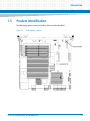
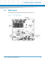
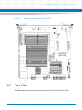
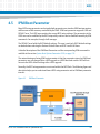
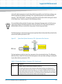
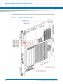
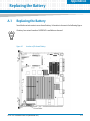
The location of the USB 2.0 Flash Module is shown in Figure "ATCA-7367 Blade Layout" on page
47.
Damage of Circuits
Electrostatic discharge and incorrect module installation and removal can damage circuits
or shorten their life.
Before touching the module or electronic components, make sure that you are working in
an ESD-safe environment.
Removal Procedure
To remove a USB flash module, proceed as follows:
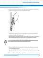
1. Remove blade from system as described in Removing the Blade on page 60.
2. Remove the screw on the left side of the flash module (see figure Figure 2-1 on
page 47).
3. Lift the flash module from the socket.
Installation Procedure
To install a USB flash module, proceed as follows:
1. Remove blade from system as described in Removing the Blade on page 60.
2. Insert new flash module in socket (see figure Figure 2-1 on page 47).
3. Tighten the screw on the left side of the flash module.
2.6
Installing and Removing the Blade
The blade is fully compatible to the AdvancedTCA standard and is designed to be used in
AdvancedTCA shelves.
56
ATCA-7367 Installation and Use (6806800K72N)