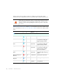
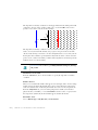
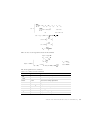
1
AC/DC Module User´s Guide VERSION 4.3 AC/DC Module User’s Guide 1998–2012 COMSOL Protected by U.S. Patents 7,519,518; 7,596,474; and 7,623,991. Patents pending. This Documentation and the Programs described herein are furnished under the COMSOL Software License Agreement (www.comsol.com/sla) and may be used or copied only under the terms of the license agreement. COMSOL, COMSOL Desktop, COMSOL Multiphysics, and LiveLink are registered trademarks or trademarks of COMSOL AB. Other product or brand names are trademarks or registered trademarks of their respective holders. Version: May 2012 COMSOL 4.3 Contact Information Visit www.comsol.com/contact for a searchable list of all COMSOL offices and local representatives. From this web page, search the contacts and find a local sales representative, go to other COMSOL websites, request information and pricing, submit technical support queries, subscribe to the monthly eNews email newsletter, and much more. If you need to contact Technical Support, an online request form is located at www.comsol.com/support/contact. Other useful links include: • Technical Support www.comsol.com/support • Software updates: www.comsol.com/support/updates • Online community: www.comsol.com/community • Events, conferences, and training: www.comsol.com/events • Tutorials: www.comsol.com/products/tutorials • Knowledge Base: www.comsol.com/support/knowledgebase Part No. CM020101 C o n t e n t s Chapter 1: Introduction About the AC/DC Module 14 What Can the AC/DC Module Do? . . . . . . . . . . . . . . . . 14 AC/DC Module Physics Guide . . . . . . . . . . . . . . . . . . 15 AC/DC Module Study Availability . . . . . . . . . . . . . . . . 17 The Model Builder Show and Hide Physics Options . . . . . . . . . . 18 Where Do I Access the Documentation and Model Library? . . . . . . 20 Typographical Conventions . . . . . . . . . . . . . . . . . . . 22 Overview of the User’s Guide 25 Chapter 2: Review of Electromagnetics Fundamentals of Electromagnetics 30 Maxwell’s Equations . . . . . . . . . . . . . . . . . . . . . . 30 Constitutive Relations . . . . . . . . . . . . . . . . . . . . . 31 Potentials. . . . . . . . . . . . . . . . . . . . . . . . . . 33 Reduced Potential PDE Formulations . . . . . . . . . . . . . . . 33 Electromagnetic Energy . . . . . . . . . . . . . . . . . . . . 34 The Quasi-Static Approximation and the Lorentz Term . . . . . . . . 35 Material Properties . . . . . . . . . . . . . . . . . . . . . . 36 About the Boundary and Interface Conditions . . . . . . . . . . . . 37 Phasors . . . . . . . . . . . . . . . . . . . . . . . . . . 38 References for Electromagnetic Theory . . . . . . . . . . . . . . 39 Electromagnetic Forces 40 Overview of Forces in Continuum Mechanics . . . . . . . . . . . . 40 Forces on an Elastic Solid Surrounded by Vacuum or Air . . . . . . . . 42 Torque. . . . . . . . . . . . . . . . . . . . . . . . . . . 43 Forces in Stationary Fields . . . . . . . . . . . . . . . . . . . 44 Forces in a Moving Body . . . . . . . . . . . . . . . . . . . . 47 CONTENTS |3 Electromagnetic Energy and Virtual Work . . . . . . . . . . . . . 50 Electromagnetic Quantities 52 References for the AC/DC Interfaces 54 Chapter 3: Modeling with the AC/DC Module Preparing for Modeling 56 What Problems Can You Solve? . . . . . . . . . . . . . . . . . 57 Selecting the Space Dimension for the Model Geometry . . . . . . . . 58 Simplifying the Geometry Using Boundary Conditions . . . . . . . . . 60 Applying Electromagnetic Sources . . . . . . . . . . . . . . . . 61 Selecting a Study Type . . . . . . . . . . . . . . . . . . . . . 62 2D Field Variables . . . . . . . . . . . . . . . . . . . . . . 63 Meshing and Solving . . . . . . . . . . . . . . . . . . . . . . 63 Infinite Elements 65 Modeling Unbounded Domains . . . . . . . . . . . . . . . . . 65 Known Issues When Modeling Using Infinite Elements. . . . . . . . . 68 Force and Torque Computations 70 Calculating Electromagnetic Forces and Torques . . . . . . . . . . . 70 Model Examples—Electromagnetic Forces . . . . . . . . . . . . . 71 Coil Domains 72 About the Single-Turn Coil Domain, Multi-Turn Coil Domain, and Coil Group Domain Features . . . . . . . . . . . . . . . . . . . . . . . 72 About the Coil Name . . . . . . . . . . . . . . . . . . . . . 74 Coil Excitation . . . . . . . . . . . . . . . . . . . . . . . . 74 Lumped Parameter Calculations . . . . . . . . . . . . . . . . . 78 Using Coils in 3D Models . . . . . . . . . . . . . . . . . . . 80 Computing Coil Currents . . . . . . . . . . . . . . . . . . . 83 Lumped Parameters 85 Calculating Lumped Parameters with Ohm’s Law . . . . . . . . . . . 85 4 | CONTENTS Calculating Lumped Parameters Using the Energy Method . . . . . . . 87 Studying Lumped Parameters . . . . . . . . . . . . . . . . . . 88 Lumped Parameter Conversion . . . . . . . . . . . . . . . . . 89 Lumped Ports with Voltage Input 90 About Lumped Ports . . . . . . . . . . . . . . . . . . . . . 90 Lumped Port Parameters . . . . . . . . . . . . . . . . . . . . 91 S-Parameters and Ports 93 S-Parameters in Terms of Electric Field . . . . . . . . . . . . . . 93 S-Parameter Calculations in COMSOL Multiphysics: Lumped Ports . . . . 94 S-Parameter Variables . . . . . . . . . . . . . . . . . . . . . 94 Connecting to Electrical Circuits 95 About Connecting Electrical Circuits to Physics Interfaces . . . . . . . 95 Connecting Electrical Circuits Using Predefined Couplings . . . . . . . 96 Connecting Electrical Circuits by User-Defined Couplings . . . . . . . 96 Importing ECAD Files 98 Overview of the ECAD Import . . . . . . . . . . . . . . . . . 98 Importing ODB++(X) Files . . . . . . . . . . . . . . . . . . . 99 Importing GDS-II Files . . . . . . . . . . . . . . . . . . . . . 99 Importing NETEX-G Files . . . . . . . . . . . . . . . . . . 101 ECAD Import Options . . . . . . . . . . . . . . . . . . . 103 Meshing an Imported Geometry . . . . . . . . . . . . . . . . 106 Troubleshooting ECAD Import . . . . . . . . . . . . . . . . 107 Chapter 4: The Electric Field Interfaces The Electrostatics Interface 110 Domain, Boundary, Edge, Point, and Pair Conditions for the Electrostatics Interface . . . . . . . . . . . . . . . . . . . . . . . . . 112 Charge Conservation . . . . . . . . . . . . . . . . . . . . 114 Space Charge Density . . . . . . . . . . . . . . . . . . . . 116 Force Calculation. . . . . . . . . . . . . . . . . . . . . . 116 Initial Values. . . . . . . . . . . . . . . . . . . . . . . . 117 CONTENTS |5 Ground . . . . . . . . . . . . . . . . . . . . . . . . . 117 Electric Potential . . . . . . . . . . . . . . . . . . . . . . 118 Surface Charge Density . . . . . . . . . . . . . . . . . . . 119 External Surface Charge Accumulation 119 . . . . . . . . . . . . . Dielectric Shielding . . . . . . . . . . . . . . . . . . . . . 120 Terminal . . . . . . . . . . . . . . . . . . . . . . . . . 121 Floating Potential . . . . . . . . . . . . . . . . . . . . . . 122 Electric Displacement Field . . . . . . . . . . . . . . . . . . 123 Distributed Capacitance . . . . . . . . . . . . . . . . . . . 124 Periodic Condition . . . . . . . . . . . . . . . . . . . . . 125 Zero Charge . . . . . . . . . . . . . . . . . . . . . . . 125 Thin Low Permittivity Gap . . . . . . . . . . . . . . . . . . 126 Line Charge . . . . . . . . . . . . . . . . . . . . . . . 127 Line Charge (on Axis) . . . . . . . . . . . . . . . . . . . . 127 Line Charge (Out-of-Plane) . . . . . . . . . . . . . . . . . . 128 Point Charge . . . . . . . . . . . . . . . . . . . . . . . 129 Point Charge (on Axis) . . . . . . . . . . . . . . . . . . . 129 Change Cross-Section . . . . . . . . . . . . . . . . . . . . 130 Change Thickness (Out-of-Plane). . . . . . . . . . . . . . . . 131 Infinite Elements . . . . . . . . . . . . . . . . . . . . . . 132 Electrostatic Point Dipole . . . . . . . . . . . . . . . . . . 132 The Electric Currents Interface 133 Domain, Boundary, Edge, Point, and Pair Features for the Electric Currents Interface . . . . . . . . . . . . . . . . . . . . . . . . . 135 Current Conservation . . . . . . . . . . . . . . . . . . . . 137 Floating Potential . . . . . . . . . . . . . . . . . . . . . . 139 Archie’s Law 140 . . . . . . . . . . . . . . . . . . . . . . . Porous Media . . . . . . . . . . . . . . . . . . . . . . . 141 External Current Density. . . . . . . . . . . . . . . . . . . 142 Current Source . . . . . . . . . . . . . . . . . . . . . . 143 Initial Values. . . . . . . . . . . . . . . . . . . . . . . . 143 Boundary Current Source . . . . . . . . . . . . . . . . . . 144 Normal Current Density . . . . . . . . . . . . . . . . . . . 144 Distributed Impedance. . . . . . . . . . . . . . . . . . . . 145 Electric Shielding . . . . . . . . . . . . . . . . . . . . . . 146 Electric Insulation 6 | CONTENTS . . . . . . . . . . . . . . . . . . . . . 148 Contact Impedance . . . . . . . . . . . . . . . . . . . . . 149 Sector Symmetry . . . . . . . . . . . . . . . . . . . . . . 151 Line Current Source . . . . . . . . . . . . . . . . . . . . 152 Line Current Source (on Axis). . . . . . . . . . . . . . . . . 153 Point Current Source . . . . . . . . . . . . . . . . . . . . 153 Point Current Source (on Axis) . . . . . . . . . . . . . . . . 154 Electric Point Dipole . . . . . . . . . . . . . . . . . . . . 155 Electric Point Dipole (on Axis). . . . . . . . . . . . . . . . . 156 The Electric Currents, Shell Interface 157 Boundary, Edge, Point, and Pair Conditions for the Electric Currents, Shell Interface . . . . . . . . . . . . . . . . . . . . . . . . . 159 Current Conservation . . . . . . . . . . . . . . . . . . . . 161 Initial Values. . . . . . . . . . . . . . . . . . . . . . . . 163 Current Source . . . . . . . . . . . . . . . . . . . . . . 163 Change Shell Thickness . . . . . . . . . . . . . . . . . . . 163 Normal Current Density . . . . . . . . . . . . . . . . . . . 164 Electric Shielding . . . . . . . . . . . . . . . . . . . . . . 164 Theory of Electric Fields 166 Charge Relaxation Theory . . . . . . . . . . . . . . . . . . 166 Theory for the Electrostatics Interface 170 Electrostatics Equations . . . . . . . . . . . . . . . . . . . 170 Theory for the Electric Currents Interface 172 Electric Currents Equations in Steady State . . . . . . . . . . . . 172 Effective Conductivity in Porous Media and Mixtures . . . . . . . . 173 Effective Relative Permeability in Porous Media and Mixtures . . . . . 174 Archie’s Law Theory . . . . . . . . . . . . . . . . . . . . 175 Dynamic Electric Currents Equations . . . . . . . . . . . . . . 176 Reference for the Electric Currents Interface . . . . . . . . . . . 177 Theory for the Electric Currents, Shell Interface 178 Electric Currents, Shell Equations in Steady State. . . . . . . . . . 178 Dynamic Electric Currents Equations . . . . . . . . . . . . . . 178 CONTENTS |7 Chapter 5: The Magnetic Field Interfaces The Magnetic Fields Interface 180 Domain, Boundary, Point, and Pair Conditions for the Magnetic Fields Interface 183 Ampère’s Law . . . . . . . . . . . . . . . . . . . . . . . 186 External Current Density. . . . . . . . . . . . . . . . . . . 189 Velocity (Lorentz Term) . . . . . . . . . . . . . . . . . . . 189 Initial Values. . . . . . . . . . . . . . . . . . . . . . . . 190 Magnetic Insulation . . . . . . . . . . . . . . . . . . . . . 191 Magnetic Field . . . . . . . . . . . . . . . . . . . . . . . 192 Surface Current . . . . . . . . . . . . . . . . . . . . . . 192 Magnetic Potential . . . . . . . . . . . . . . . . . . . . . 193 Perfect Magnetic Conductor . . . . . . . . . . . . . . . . . 194 Line Current (Out-of-Plane) 195 Magnetic Fields Interface Advanced Features 197 Gauge Fixing for A-field . . . . . . . . . . . . . . . . . . . 198 Multi-Turn Coil Domain . . . . . . . . . . . . . . . . . . . 199 Single-Turn Coil Domain . . . . . . . . . . . . . . . . . . . 202 Gap Feed . . . . . . . . . . . . . . . . . . . . . . . . . 205 Boundary Feed 205 . . . . . . . . . . . . . . . . . . . . . . Ground . . . . . . . . . . . . . . . . . . . . . . . . . 206 Reference Edge . . . . . . . . . . . . . . . . . . . . . . 206 Automatic Current Calculation . . . . . . . . . . . . . . . . 207 Electric Insulation . . . . . . . . . . . . . . . . . . . . . 208 Input . . . . . . . . . . . . . . . . . . . . . . . . . . 208 Output . . . . . . . . . . . . . . . . . . . . . . . . . Coil Group Domain 8 | CONTENTS . . . . . . . . . . . . . . . . . 208 . . . . . . . . . . . . . . . . . . . . 209 Reversed Current Direction . . . . . . . . . . . . . . . . . 210 Harmonic Perturbation . . . . . . . . . . . . . . . . . . . 210 Lumped Port . . . . . . . . . . . . . . . . . . . . . . . 211 Edge Current . . . . . . . . . . . . . . . . . . . . . . . 214 External Magnetic Vector Potential . . . . . . . . . . . . . . . 215 Impedance Boundary Condition . . . . . . . . . . . . . . . . 215 Transition Boundary Condition . . . . . . . . . . . . . . . . 217 Thin Low Permeability Gap . . . . . . . . . . . . . . . . . . 218 Magnetic Point Dipole . . . . . . . . . . . . . . . . . . . . 219 Magnetic Point Dipole (on Axis) . . . . . . . . . . . . . . . . 220 The Magnetic Fields, No Currents Interface 221 Domain, Boundary, Point, and Pair Features for the Magnetic Fields, No Currents Interface . . . . . . . . . . . . . . . . . . . . . . . . . 222 Magnetic Flux Conservation. . . . . . . . . . . . . . . . . . 224 Initial Values. . . . . . . . . . . . . . . . . . . . . . . . 225 Infinite Elements . . . . . . . . . . . . . . . . . . . . . . 225 Magnetic Insulation . . . . . . . . . . . . . . . . . . . . . 226 Magnetic Flux Density . . . . . . . . . . . . . . . . . . . . 226 Zero Magnetic Scalar Potential. . . . . . . . . . . . . . . . . 227 External Magnetic Flux Density . . . . . . . . . . . . . . . . 227 Magnetic Shielding . . . . . . . . . . . . . . . . . . . . . 228 Thin Low Permeability Gap . . . . . . . . . . . . . . . . . . 228 The Rotating Machinery, Magnetic Interface 230 Domain and Shared Features for the Rotating Machinery, Magnetic Interface . 232 Initial Values. . . . . . . . . . . . . . . . . . . . . . . . 233 Electric Field Transformation . . . . . . . . . . . . . . . . . 234 Prescribed Rotation . . . . . . . . . . . . . . . . . . . . . 234 Prescribed Rotational Velocity . . . . . . . . . . . . . . . . . 234 Theory of Magnetic and Electric Fields 235 Maxwell’s Equations . . . . . . . . . . . . . . . . . . . . . 235 Magnetic and Electric Potentials . . . . . . . . . . . . . . . . 235 Gauge Transformations . . . . . . . . . . . . . . . . . . . 236 Selecting a Particular Gauge. . . . . . . . . . . . . . . . . . 237 The Gauge and the Equation of Continuity for Dynamic Fields. . . . . 237 Explicit Gauge Fixing/Divergence Constraint . . . . . . . . . . . 237 Ungauged Formulations and Current Conservation . . . . . . . . . 238 Time-Harmonic Magnetic Fields . . . . . . . . . . . . . . . . 239 Theory for the Magnetic Fields Interface 240 Magnetostatics Equation . . . . . . . . . . . . . . . . . . . 240 Frequency Domain Equation . . . . . . . . . . . . . . . . . 241 Transient Equation . . . . . . . . . . . . . . . . . . . . . 242 CONTENTS |9 Theory for the Magnetic Fields, No Currents Interface 243 Chapter 6: The Magnetic and Electric Fields Interface The Magnetic and Electric Fields Interface 246 Domain, Boundary, Edge, Point, and Pair Features for the Magnetic and Electric Fields Interface . . . . . . . . . . . . . . . . . . . . . . 249 Ampère’s Law and Current Conservation . . . . . . . . . . . . 253 Initial Values. . . . . . . . . . . . . . . . . . . . . . . . 254 Theory for the Magnetic and Electric Fields Interface 255 Magnetostatics Equations . . . . . . . . . . . . . . . . . . . 255 Frequency Domain Equations . . . . . . . . . . . . . . . . . 256 Chapter 7: The Electrical Circuit Interface 10 | C O N T E N T S The Electrical Circuit Interface 258 Ground Node . . . . . . . . . . . . . . . . . . . . . . . 259 Resistor . . . . . . . . . . . . . . . . . . . . . . . . . 260 Capacitor. . . . . . . . . . . . . . . . . . . . . . . . . 260 Inductor . . . . . . . . . . . . . . . . . . . . . . . . . 260 Voltage Source. . . . . . . . . . . . . . . . . . . . . . . 260 Current Source . . . . . . . . . . . . . . . . . . . . . . 261 Voltage-Controlled Voltage Source . . . . . . . . . . . . . . . 262 Voltage-Controlled Current Source . . . . . . . . . . . . . . . 262 Current-Controlled Voltage Source . . . . . . . . . . . . . . . 262 Current-Controlled Current Source . . . . . . . . . . . . . . 263 Subcircuit Definition . . . . . . . . . . . . . . . . . . . . 263 Subcircuit Instance . . . . . . . . . . . . . . . . . . . . . 264 NPN BJT . . . . . . . . . . . . . . . . . . . . . . . . . 264 n-Channel MOSFET . . . . . . . . . . . . . . . . . . . . . 264 Diode . . . . . . . . . . . . . . . . . . . . . . . . . . 265 External I vs. U . . . . . . . . . . . . . . . . . . . . . . 266 External U vs. I . . . . . . . . . . . . . . . . . . . . . . 267 External I-Terminal . . . . . . . . . . . . . . . . . . . . . 267 SPICE Circuit Import . . . . . . . . . . . . . . . . . . . . 268 Theory for the Electrical Circuit Interface 269 Electric Circuit Modeling and the Semiconductor Device Models. . . . 269 NPN Bipolar Transistor . . . . . . . . . . . . . . . . . . . 270 n-Channel MOS Transistor . . . . . . . . . . . . . . . . . . 273 Diode . . . . . . . . . . . . . . . . . . . . . . . . . . 276 References for the Electrical Circuit Interface . . . . . . . . . . . 279 C h a p t e r 8 : T h e H e a t Tr a n s f e r B r a n c h The Induction Heating Interface 282 Domain, Boundary, Edge, Point, and Pair Features for the Induction Heating Interface . . . . . . . . . . . . . . . . . . . . . . . . . 284 Induction Heating Model . . . . . . . . . . . . . . . . . . . 287 Electromagnetic Heat Source . . . . . . . . . . . . . . . . . 288 Initial Values. . . . . . . . . . . . . . . . . . . . . . . . 288 Chapter 9: Materials Material Library and Databases 292 About the Material Databases . . . . . . . . . . . . . . . . . 292 About Using Materials in COMSOL . . . . . . . . . . . . . . . 295 Opening the Material Browser . . . . . . . . . . . . . . . . 297 . . . . . . . . . . . . . . . . . . 298 Using Material Properties Using the AC/DC Material Database 299 Chapter 10: Glossary Glossary of Terms 302 CONTENTS | 11 12 | C O N T E N T S 1 Introduction This guide describes the AC/DC Module, an optional add-on package for COMSOL Multiphysics designed to assist you to solve and model low-frequency electromagnetics. This chapter introduces you to the capabilities of the module including an introduction to the modeling stages and some realistic and illustrative models. A summary of the physics interfaces and where you can find documentation and model examples is also included. The last section is a brief overview with links to each chapter in this guide. In this chapter: • About the AC/DC Module • Overview of the User’s Guide 13 About the AC/DC Module In this section: • What Can the AC/DC Module Do? • AC/DC Module Physics Guide • AC/DC Module Study Availability • The Model Builder Show and Hide Physics Options • Where Do I Access the Documentation and Model Library? • Typographical Conventions What Can the AC/DC Module Do? The AC/DC Module provides a unique environment for simulation of AC/DC electromagnetics in 2D and 3D. The module is a powerful tool for detailed analysis of coils, capacitors, and electrical machinery. With this module you can run static, quasi-static, transient, and time-harmonic simulations in an easy-to-use graphical user interface. The available physics interfaces cover the following types of electromagnetics field simulations: • Electrostatics • Electric currents in conductive media • Magnetostatics • Low-frequency electromagnetics Material properties include inhomogeneous and fully anisotropic materials, media with gains or losses, and complex-valued material properties. Infinite elements makes it possible to model unbounded domains. In addition to the standard results and visualization functionality, the module supports direct computation of lumped parameters such as capacitances and inductances as well as electromagnetic forces. Like all COMSOL modules, there is a library of ready-to-run models that make it quicker and easier to analyze discipline-specific problems. In addition, any model you develop is described in terms of the underlying partial differential equations, offering a unique way to see the underlying physical laws of a simulation. 14 | CHAPTER 1: INTRODUCTION The interfaces are fully multiphysics enabled—couple them to any other interface in COMSOL Multiphysics or the other modules. For example, to find the heat distribution in a motor, first find the current in the coils using one of the quasi-static interfaces in this module and then couple it to a heat equation in the main COMSOL Multiphysics package or the Heat Transfer Module. This forms a powerful multiphysics model that solves all the equations simultaneously. COMSOL Multiphysics also has an interface to the MATLAB technical computing environment. If you have a MATLAB license, save it as a Model M-file—a script file that runs in MATLAB. This module also provides interfaces for modeling electrical circuits and importing ECAD drawings. • Building a COMSOL Model in the COMSOL Multiphysics User’s Guide • AC/DC Module Physics Guide See Also • AC/DC Module Study Availability • Where Do I Access the Documentation and Model Library? • Typographical Conventions AC/DC Module Physics Guide The physics interfaces in the AC/DC Module form a complete set of simulation tools for electromagnetic field simulations. To select the right physics interface for describing the real-life physics, the geometric properties and the time variations of the fields need to be considered. The interfaces solve for these physical quantities—the electric scalar potential V, the magnetic vector potential A, and the magnetic scalar potential Vm. Each interface has a Tag which is of special importance when performing multiphysics simulations. This tag helps distinguish between physics interfaces and the variables defined by the interface have an underscore plus the physics interface tag appended to their names. The Model Wizard is an easy way to select the physics interface and study type when creating a model for the first time, and physics interfaces can be added to an existing model at any time. Full instructions for selecting interfaces and setting up a model are in the COMSOL Multiphysics User’s Guide. ABOUT THE AC/DC MODULE | 15 In 2D, in-plane and out-of-plane variants are available for problems with a planar symmetry as well as axisymmetric interfaces for problems with a cylindrical symmetry. See Important When using an axisymmetric interface it is important that the horizontal axis represents the r direction and the vertical axis the z direction, and that the geometry in the right half-plane (that is, for positive r only) must be created. What Problems Can You Solve? and Table 1-1 for information about the available study types and variables. See also Overview of the User’s Guide for links to the chapters in this guide. PHYSICS ICON TAG SPACE DIMENSION PRESET STUDIES Electrostatics* es all dimensions stationary; time dependent Electric Currents* ec all dimensions stationary; frequency domain; time dependent; small signal analysis, frequency domain Electric Currents Shell ecs 3D, 2D, 2D axisymmetric stationary; frequency domain; time dependent; small signal analysis, frequency domain Magnetic Fields* mf 3D, 2D, 2D axisymmetric stationary; frequency domain; time dependent; small signal analysis, frequency domain; coil current calculation Magnetic and Electric Fields mef 3D, 2D, 2D axisymmetric stationary; frequency domain; small signal analysis, frequency domain Magnetic Fields, No Currents mfnc all dimensions stationary; time dependent Rotating Machinery, Magnetic rmm 2D stationary; time dependent Electrical Circuit cir Not space dependent stationary; frequency domain; time dependent AC/DC 16 | CHAPTER 1: INTRODUCTION PHYSICS ICON TAG SPACE DIMENSION PRESET STUDIES ih 3D, 2D, 2D axisymmetric stationary; frequency domain; time dependent; frequency stationary; frequency transient Electromagnetic Heating Induction Heating * This is an enhanced interface, which is included with the base COMSOL package but has added functionality for this module. AC/DC Module Study Availability TABLE 1-1: AC/DC MODULE DEPENDENT VARIABLES, FIELD COMPONENTS, AND PRESET STUDY AVAILABILITY V x y z Electric Currents, Shell ecs V x y z Magnetic Fields mf A x y z x y z Magnetic and Electric Fields mef V, A x y z x y z x y z x y z x y z x y z x y z x y z FREQUENCY-TRANSIENT ec FREQUENCY-STATIONARY Electric Currents ** SMALL-SIGNAL ANALYSIS, FREQUENCY DOMAIN x y z FREQUENCY DOMAIN V TIME DEPENDENT es STATIONARY Electrostatics PRESET STUDIES CURRENT DENSITY FIELD * COMPONENTS MAGNETIC POTENTIAL DEPENDENT VARIABLES ELECTRIC FIELD TAG MAGNETIC FIELD PHYSICS INTERFACE ABOUT THE AC/DC MODULE | 17 TABLE 1-1: AC/DC MODULE DEPENDENT VARIABLES, FIELD COMPONENTS, AND PRESET STUDY AVAILABILITY A x y Electrical Circuit cir not applicable Induction Heating ih A,T, J x y z z x y z z x y z z x y z FREQUENCY-TRANSIENT rmm FREQUENCY-STATIONARY Rotating Machinery, Magnetic SMALL-SIGNAL ANALYSIS, FREQUENCY DOMAIN x y z FREQUENCY DOMAIN Vm TIME DEPENDENT mfnc STATIONARY Magnetic Fields, No Currents ** PRESET STUDIES CURRENT DENSITY FIELD * COMPONENTS MAGNETIC POTENTIAL DEPENDENT VARIABLES ELECTRIC FIELD TAG MAGNETIC FIELD PHYSICS INTERFACE * These are the nonzero field components. For Cartesian coordinates, these are indexed by x, y, and z; for cylindrical coordinates, r, , and z are used. ** Custom studies are also available based on the interface, for example, Eigenfrequency and Eigenvalue. The Model Builder Show and Hide Physics Options There are several features available on many physics interfaces or individual nodes. This section is a short overview of the options and includes links to the COMSOL Multiphysics User’s Guide or COMSOL Multiphysics Reference Guide where additional information is available. Important 18 | The links to the features described in the COMSOL Multiphysics User’s Guide and COMSOL Multiphysics Reference Guide do not work in the PDF, only from within the online help. CHAPTER 1: INTRODUCTION Tip To locate and search all the documentation for this information, in COMSOL, select Help>Documentation from the main menu and either enter a search term or look under a specific module in the documentation tree. SHOW MORE PHYSICS OPTIONS To display additional features for the physics interfaces and feature nodes, click the Show button ( ) on the Model Builder and then select the applicable option. After clicking the Show button ( ), some sections display on the settings window when a node is clicked and other features are available from the context menu when a node is right-clicked. For each, the additional sections that can be displayed include Equation, Advanced Settings, Discretization, Consistent Stabilization, and Inconsistent Stabilization. You can also click the Expand Sections button ( ) in the Model Builder to always show ) and select Reset to Default to reset to some sections or click the Show button ( display only the Equation and Override and Contribution sections. For most physics nodes, both the Equation and Override and Contribution sections are ) and then select Equation View to display always available. Click the Show button ( the Equation View node under all physics nodes in the Model Builder. Availability of each feature, and whether it is described for a particular physics node, is based on the individual physics selected. For example, the Discretization, Advanced Settings, Consistent Stabilization, and Inconsistent Stabilization sections are often described individually throughout the documentation as there are unique settings. SECTION CROSS REFERENCE LOCATION IN COMSOL MULTIPHYSICS USER GUIDE OR REFERENCE GUIDE Show More Options and Expand Sections • Showing and Expanding Advanced Physics Sections User’s Guide • The Model Builder Window Discretization • Show Discretization User’s Guide • Element Types and Discretization • Finite Elements Reference Guide • Discretization of the Equations ABOUT THE AC/DC MODULE | 19 SECTION CROSS REFERENCE LOCATION IN COMSOL MULTIPHYSICS USER GUIDE OR REFERENCE GUIDE Discretization - Splitting of complex variables Compile Equations Reference Guide Pair Selection • Identity and Contact Pairs User’s Guide • Specifying Boundary Conditions for Identity Pairs Consistent and Inconsistent Stabilization Show Stabilization User’s Guide • Stabilization Techniques Reference Guide • Numerical Stabilization Geometry Working with Geometry User’s Guide Constraint Settings Using Weak Constraints User’s Guide Where Do I Access the Documentation and Model Library? A number of Internet resources provide more information about COMSOL Multiphysics, including licensing and technical information. The electronic documentation, Dynamic Help, and the Model Library are all accessed through the COMSOL Desktop. Important If you are reading the documentation as a PDF file on your computer, the blue links do not work to open a model or content referenced in a different user’s guide. However, if you are using the online help in COMSOL Multiphysics, these links work to other modules, model examples, and documentation sets. THE DOCUMENTATION The COMSOL Multiphysics User’s Guide and COMSOL Multiphysics Reference Guide describe all interfaces and functionality included with the basic COMSOL Multiphysics license. These guides also have instructions about how to use COMSOL Multiphysics and how to access the documentation electronically through the COMSOL Multiphysics help desk. 20 | CHAPTER 1: INTRODUCTION To locate and search all the documentation, in COMSOL Multiphysics: • Press F1 for Dynamic Help, • Click the buttons on the toolbar, or • Select Help>Documentation ( ) or Help>Dynamic Help ( ) from the main menu and then either enter a search term or look under a specific module in the documentation tree. THE MODEL LIBRARY Each model comes with documentation that includes a theoretical background and step-by-step instructions to create the model. The models are available in COMSOL as MPH-files that you can open for further investigation. You can use the step-by-step instructions and the actual models as a template for your own modeling and applications. SI units are used to describe the relevant properties, parameters, and dimensions in most examples, but other unit systems are available. ) from the main menu, and To open the Model Library, select View>Model Library ( then search by model name or browse under a module folder name. Click to highlight any model of interest, and select Open Model and PDF to open both the model and the documentation explaining how to build the model. Alternatively, click the Dynamic Help button ( ) or select Help>Documentation in COMSOL to search by name or browse by module. The model libraries are updated on a regular basis by COMSOL in order to add new models and to improve existing models. Choose View>Model Library Update ( ) to update your model library to include the latest versions of the model examples. If you have any feedback or suggestions for additional models for the library (including those developed by you), feel free to contact us at [email protected]. CONTACTING COMSOL BY EMAIL For general product information, contact COMSOL at [email protected]. To receive technical support from COMSOL for the COMSOL products, please contact your local COMSOL representative or send your questions to [email protected]. An automatic notification and case number is sent to you by email. ABOUT THE AC/DC MODULE | 21 COMSOL WEB SITES Main Corporate web site www.comsol.com Worldwide contact information www.comsol.com/contact Technical Support main page www.comsol.com/support Support Knowledge Base www.comsol.com/support/knowledgebase Product updates www.comsol.com/support/updates COMSOL User Community www.comsol.com/community Typographical Conventions All COMSOL user’s guides use a set of consistent typographical conventions that make it easier to follow the discussion, understand what you can expect to see on the graphical user interface (GUI), and know which data must be entered into various data-entry fields. In particular, these conventions are used throughout the documentation: 22 | CONVENTION EXAMPLE text highlighted in blue Click text highlighted in blue to go to other information in the PDF. When you are using the online help desk in COMSOL Multiphysics, these links also work to other modules, model examples, and documentation sets. boldface font A boldface font indicates that the given word(s) appear exactly that way on the COMSOL Desktop (or, for toolbar buttons, in the corresponding tip). For example, the Model ) is often referred to and this is the Builder window ( window that contains the model tree. As another example, the instructions might say to click the Zoom Extents button ( ), and this means that when you hover over the button with your mouse, the same label displays on the COMSOL Desktop. Forward arrow symbol > The forward arrow symbol > is instructing you to select a series of menu items in a specific order. For example, Options>Preferences is equivalent to: From the Options menu, choose Preferences. Code (monospace) font A Code (monospace) font indicates you are to make a keyboard entry in the user interface. You might see an instruction such as “Enter (or type) 1.25 in the Current density field.” The monospace font also is an indication of programming code or a variable name. CHAPTER 1: INTRODUCTION CONVENTION EXAMPLE Italic Code (monospace) font An italic Code (monospace) font indicates user inputs and parts of names that can vary or be defined by the user. Arrow brackets <> following the Code (monospace) or Code (italic) fonts The arrow brackets included in round brackets after either a monospace Code or an italic Code font means that the content in the string can be freely chosen or entered by the user, such as feature tags. For example, model.geom(<tag>) where <tag> is the geometry’s tag (an identifier of your choice). When the string is predefined by COMSOL, no bracket is used and this indicates that this is a finite set, such as a feature name. KEY TO THE GRAPHICS Throughout the documentation, additional icons are used to help navigate the information. These categories are used to draw your attention to the information based on the level of importance, although it is always recommended that you read these text boxes. ICON NAME DESCRIPTION Caution A Caution icon is used to indicate that the user should proceed carefully and consider the next steps. It might mean that an action is required, or if the instructions are not followed, that there will be problems with the model solution. Important An Important icon is used to indicate that the information provided is key to the model building, design, or solution. The information is of higher importance than a note or tip, and the user should endeavor to follow the instructions. Note A Note icon is used to indicate that the information may be of use to the user. It is recommended that the user read the text. Tip A Tip icon is used to provide information, reminders, short cuts, suggestions of how to improve model design, and other information that may or may not be useful to the user. See Also The See Also icon indicates that other useful information is located in the named section. If you are working on line, click the hyperlink to go to the information directly. When the link is outside of the current PDF document, the text indicates this, for example See The Laminar Flow Interface in the COMSOL Multiphysics User’s Guide. Note that if you are in COMSOL Multiphysics’ online help, the link will work. ABOUT THE AC/DC MODULE | 23 ICON NAME DESCRIPTION Model The Model icon is used in the documentation as well as in COMSOL Multiphysics from the View>Model Library menu. If you are working online, click the link to go to the PDF version of the step-by-step instructions. In some cases, a model is only available if you have a license for a specific module. These examples occur in the COMSOL Multiphysics User’s Guide. The Model Library path describes how to find the actual model in COMSOL Multiphysics, for example If you have the RF Module, see Radar Cross Section: Model Library path RF_Module/Tutorial_Models/radar_cross_section Space Dimension 24 | CHAPTER 1: INTRODUCTION Another set of icons are also used in the Model Builder—the model space dimension is indicated by 0D , 1D , 1D axial symmetry , 2D , 2D axial symmetry , and 3D icons. These icons are also used in the documentation to clearly list the differences to an interface, feature node, or theory section, which are based on space dimension. Overview of the User’s Guide The AC/DC Module User’s Guide gets you started with modeling using COMSOL Multiphysics. The information in this guide is specific to this module. Instructions how to use COMSOL in general are included with the COMSOL Multiphysics User’s Guide. Tip As detailed in the section Where Do I Access the Documentation and Model Library? this information is also searchable from the COMSOL Multiphysics software Help menu. TA B L E O F C O N T E N T S , G L O S S A R Y, A N D I N D E X To help you navigate through this guide, see the Contents, Glossary, and Index. THEORY OF ELECTROMAGNETICS In the Review of Electromagnetics chapter contains an overview of the theory behind the AC/DC Module. It is intended for readers that wish to understand what goes on in the background when using the physics interfaces and discusses the Fundamentals of Electromagnetics, Electromagnetic Forces, and Electromagnetic Quantities. MODELING WITH THE AC/DC MODULE In the Modeling with the AC/DC Module chapter, the goal is to familiarize you with the modeling procedure using this particular module. Topics include Preparing for Modeling, Infinite Elements, Force and Torque Computations, Lumped Parameters, and Importing ECAD Files. ELECTRIC FIELDS The Electric Field Interfaces chapter describes these interfaces and includes the underlying theory for each interface at the end of the chapter: • The Electrostatics Interface, which simulates electric fields in dielectric materials with a fixed charge present. Preset stationary and time dependent study types are available. O V E R V I E W O F T H E U S E R ’S G U I D E | 25 • The Electric Currents Interface, which simulates the current in a conductive and capacitive material under the influence of an electric field. All three study types (stationary, frequency domain, and time dependent) are available. • The Electric Currents, Shell Interface, which simulates the current in a conductive and capacitive shell under the influence of an electric field. All three study types (stationary, frequency domain and time dependent) are available. MAGNETIC FIELDS The Magnetic Field Interfaces chapter describes these interfaces and includes the underlying theory for each interface at the end of the chapter: • The Magnetic Fields Interface, which handles problems for magnetic fields with prescribed currents. All three study types (stationary, frequency domain, and time dependent) are available. • The Magnetic Fields, No Currents Interface, which handles magnetic fields without currents. When no currents are present, the problem is easier to solve using the magnetic scalar potential. The stationary and time dependent study types are available. • The Rotating Machinery, Magnetic Interface is available with 2D models only. It combines an out-of-plane magnetic fields (magnetic vector potential) formulation with a selection of predefined frames for prescribed rotation or rotation velocity—it shares most of its features with the Magnetic Fields interface. This interface requires that the geometry is created as an assembly from individual parts for the rotor and stator. MAGNETIC AND ELECTRIC FIELDS The Magnetic and Electric Fields Interface chapter describes the interface, which handles problems for magnetic and electric fields. It is based on the magnetic vector potential and the electric scalar potential. The stationary and frequency domain study types are available. The underlying theory for the interface is included at the end of the chapter. ELECTRICAL CIRCUIT The Electrical Circuit Interface chapter describes the interface, which has the equations for modeling electrical circuits with or without connections to a distributed fields model, solving for the voltages, currents, and charges associated with the circuit elements. The underlying theory for the interface is included at the end of the chapter. 26 | CHAPTER 1: INTRODUCTION H E A T TR A N S F E R The Heat Transfer Branch chapter describes the interface, which combines all features from the Magnetic Fields interface in the time harmonic formulation with the Heat Transfer interface for modeling of induction and eddy current heating. Heat transfer through conduction and convection in solids and free media (fluids) is supported by physics interfaces shipped with the basic COMSOL Multiphysics license. See Also The Heat Transfer Interface, The Joule Heating Interface, and Theory for the Heat Transfer Interfaces in the COMSOL Multiphysics User’s Guide. MATERIALS The Materials chapter has details about the electromagnetic material properties that you can store in the material databases such as electrical conductivity and resistivity, relative permittivity, relative permeability, nonlinear BH-curves, and refractive index. O V E R V I E W O F T H E U S E R ’S G U I D E | 27 28 | CHAPTER 1: INTRODUCTION 2 Review of Electromagnetics This chapter contains an overview of the theory behind the AC/DC Module. It is intended for readers that wish to understand what goes on in the background when using the physics interfaces. In this chapter: • Fundamentals of Electromagnetics • Electromagnetic Forces • Electromagnetic Quantities • References for the AC/DC Interfaces 29 Fundamentals of Electromagnetics In this section: • Maxwell’s Equations • Constitutive Relations • Potentials • Reduced Potential PDE Formulations • Electromagnetic Energy • The Quasi-Static Approximation and the Lorentz Term • Material Properties • About the Boundary and Interface Conditions • Phasors • References for Electromagnetic Theory Maxwell’s Equations The problem of electromagnetic analysis on a macroscopic level is that of solving Maxwell’s equations subject to certain boundary conditions. Maxwell’s equations are a set of equations, written in differential or integral form, stating the relationships between the fundamental electromagnetic quantities. These quantities are: • Electric field intensity E • Electric displacement or electric flux density D • Magnetic field intensity H • Magnetic flux density B • Current density J • Electric charge density The equations can be formulated in differential form or integral form. The differential form is presented here because it leads to differential equations that the finite element method can handle. For general time-varying fields, Maxwell’s equations can be written as 30 | CHAPTER 2: REVIEW OF ELECTROMAGNETICS D H = J + ------t B E = – ------t D = B = 0 The first two equations are also referred to as Maxwell-Ampère’s law and Faraday’s law, respectively. Equation three and four are two forms of Gauss’ law: the electric and magnetic form, respectively. Another fundamental equation is the equation of continuity J t = – ------ Out of the five equations mentioned, only three are independent. The first two combined with either the electric form of Gauss’ law or the equation of continuity form such an independent system. Constitutive Relations To obtain a closed system, the equations include constitutive relations that describe the macroscopic properties of the medium. They are given as D B = 0 E + P = 0 H + M J (2-1) = E where 0 is the permittivity of vacuum, 0 is the permeability of vacuum, and the electrical conductivity. In the SI system, the permeability of vacuum is chosen to be 4·107 H/m. The velocity of an electromagnetic wave in vacuum is given as c0 and the permittivity of vacuum is derived from the relation 1 0 = ---------= 8.854 10 2 c0 0 – 12 1 –9 F/m --------- 10 F/m 36 The electromagnetic constants 0, 0, and c0 are available in COMSOL Multiphysics as predefined physical constants. The electric polarization vector P describes how the material is polarized when an electric field E is present. It can be interpreted as the volume density of electric dipole FUNDAMENTALS OF ELECTROMAGNETICS | 31 moments. P is generally a function of E. Some materials can have a nonzero P also when there is no electric field present. The magnetization vector M similarly describes how the material is magnetized when a magnetic field H is present. It can be interpreted as the volume density of magnetic dipole moments. M is generally a function of H. Permanent magnets, for instance, have a nonzero M also when there is no magnetic field present. For linear materials, the polarization is directly proportional to the electric field, P0 e E , where e is the electric susceptibility. Similarly in linear materials, the magnetization is directly proportional to the magnetic field, Mm H , where m is the magnetic susceptibility. For such materials, the constitutive relations are D = 0 1 + e E = 0 r E = E B = 0 1 + m H = 0 r H = H The parameter r is the relative permittivity and r is the relative permeability of the material. Usually these are scalar properties but can, in the general case, be 3-by-3 tensors when the material is anisotropic. The properties and (without subscripts) are the permittivity and permeability of the material. GENERALIZED CONSTITUTIVE RELATIONS See Also The Charge Conservation feature describes the macroscopic properties of the medium (relating the electric displacement D with the electric field E) and the applicable material properties. For nonlinear materials, a generalized form of the constitutive relationships is useful. The relationship used for electric fields is D orE + Dr where Dr is the remanent displacement, which is the displacement when no electric field is present. Similarly, a generalized form of the constitutive relation for the magnetic field is B = 0 r H + Br where Br is the remanent magnetic flux density, which is the magnetic flux density when no magnetic field is present. For some materials, there is a nonlinear relationship between B and H such that B = f H 32 | CHAPTER 2: REVIEW OF ELECTROMAGNETICS The relation defining the current density is generalized by introducing an externally generated current Je. The resulting constitutive relation is J E + Je. Potentials Under certain circumstances it can be helpful to formulate the problems in terms of the electric scalar potential V and the magnetic vector potential A. They are given by the equalities B = A A E = – V – ------t The defining equation for the magnetic vector potential is a direct consequence of the magnetic Gauss’ law. The electric potential results from Faraday’s law. In the magnetostatic case where there are no currents present, Maxwell-Ampère’s law reduces to H0. When this holds, it is also possible to define a magnetic scalar potential by the relation H Vm. Reduced Potential PDE Formulations The reduced potential option introduces the substitution AAredAext into Maxwell-Ampère’s law: –1 A = J + dD dt DOMAIN EQUATIONS Time-Harmonic For time-harmonic quasi-static systems solving for an A formulation, the reduced potential formulation results in the following PDE: 2 –1 j – A ext + A red + A ext + A red = J e Here it is possible to interpret the term Aext as an additional remanent magnetic flux density and the term (j2Aext as an additional external current source. Transient Similarly to the time-harmonic formulation, in the transient formulation, the above substitution results in the reduced equation FUNDAMENTALS OF ELECTROMAGNETICS | 33 A ext + A red + A ext + A red = J e t –1 Static In static formulations, the induced current is zero. Maxwell-Ampère’s law reduces to –1 A ext + A red = J e In this case it is also possible to express the external field through a known external magnetic flux density, Bext. The domain equation in reduced form then reads –1 A red + B ext = J e Electromagnetic Energy The electric and magnetic energies are defined as V D E dD dV = V T D T B dt dV 0 E ------t We = 0 Wm = - dt dV V 0 H dB dV = V 0 H -----t B The time derivatives of these expressions are the electric and magnetic power D Pe = dV V E ------t Pm = - dV V H -----t B These quantities are related to the resistive and radiative energy, or energy loss, through Poynting’s theorem (Ref. 1) – D B + H ------- dV = J E dV + E H n dS V E ------V t t S where V is the computation domain and S is the closed boundary of V. The first term on the right-hand side represents the resistive losses, Ph = 34 | CHAPTER 2: REVIEW OF ELECTROMAGNETICS V J E dV which result in heat dissipation in the material. (The current density J in this expression is the one appearing in Maxwell-Ampère’s law.) The second term on the right-hand side of Poynting’s theorem represents the radiative losses, Pr = S E H n dS The quantity SE × H is called the Poynting vector. Under the assumption the material is linear and isotropic, it holds that D E 1 E ------- = E ------- = --- E E t t t 2 B 1 B 1 H ------- = --- B ------- = ------- B B t t t 2 By interchanging the order of differentiation and integration (justified by the fact that the volume is constant and the assumption that the fields are continuous in time), the result is – t - B B dV = V --2- E E + -----V J E dV + S E H n dS 2 1 1 The integrand of the left-hand side is the total electromagnetic energy density 1 1 w = w e + w m = --- E E + ------- B B 2 2 The Quasi-Static Approximation and the Lorentz Term A consequence of Maxwell’s equations is that changes in time of currents and charges are not synchronized with changes of the electromagnetic fields. The changes of the fields are always delayed relative to the changes of the sources, reflecting the finite speed of propagation of electromagnetic waves. Under the assumption that this effect can be ignored, it is possible to obtain the electromagnetic fields by considering stationary currents at every instant. This is called the quasi-static approximation. The approximation is valid provided that the variations in time are small and that the studied geometries are considerably smaller than the wavelength (Ref. 5). FUNDAMENTALS OF ELECTROMAGNETICS | 35 The quasi-static approximation implies that the equation of continuity can be written as Jand that the time derivative of the electric displacement Dt can be disregarded in Maxwell-Ampère’s law. There are also effects of the motion of the geometries. Consider a geometry moving with velocity v relative to the reference system. The force per unit charge, Fq, is then given by the Lorentz force equation: F ---- = E + v B q This means that to an observer traveling with the geometry, the force on a charged particle can be interpreted as caused by an electric field E'Ev×B. In a conductive medium, the observer accordingly sees the current density J = E + v B + Je where Je is an externally generated current density. Maxwell-Ampère’s law for quasi-static systems is consequently extended to H = E + v B + J e whereas Faraday’s law remains unchanged. Material Properties Until now, there has only been a formal introduction of the constitutive relations. These seemingly simple relations can be quite complicated at times. There are four main groups of materials where they require some consideration. A given material can belong to one or more of these groups. The groups are: • Inhomogeneous materials • Anisotropic materials • Nonlinear materials • Dispersive materials A material can belong to one or more of these groups. 36 | CHAPTER 2: REVIEW OF ELECTROMAGNETICS INHOMOGENEOUS MATERIALS Inhomogeneous materials are the least complicated. An inhomogeneous medium is one in which the constitutive parameters vary with the space coordinates so that different field properties prevail at different parts of the material structure. ANISOTROPIC MATERIALS For anisotropic materials the field relationships at any point differ for different directions of propagation. This means that a 3-by-3 tensor is necessary to properly define the constitutive relationships. If this tensor is symmetric, the material is often referred to as reciprocal. In such cases, rotate the coordinate system such that a diagonal matrix results. If two of the diagonal entries are equal, the material is uniaxially anisotropic. If none of the elements has the same value, the material is biaxially anisotropic (Ref. 2). Anisotropic parameters are needed, for example, to examine permittivity in crystals (Ref. 2) and when working with conductivity in solenoids. NONLINEAR MATERIALS Nonlinearity is the effect of variations in permittivity or permeability with the intensity of the electromagnetic field. Nonlinearity also includes hysteresis effects, where not only the current field intensities influence the physical properties of the material, but also the history of the field distribution. DISPERSIVE MATERIALS Dispersion describes changes in a wave’s velocity with wavelength. In the frequency domain dispersion is expressed with a frequency dependence of the constitutive laws. About the Boundary and Interface Conditions To get a full description of an electromagnetics problem, boundary conditions must be specified at material interfaces and physical boundaries. At interfaces between two media, the boundary conditions can be expressed mathematically as n2 E1 – E2 = 0 n2 D1 – D 2 = s n2 H1 – H2 = Js n2 B1 – B2 = 0 FUNDAMENTALS OF ELECTROMAGNETICS | 37 where s and Js denote surface charge density and surface current density, respectively, and n2 is the outward normal from medium 2. Of these four conditions, only two are independent. This is an overdetermined system of equations, so it needs to be reduced. First select either equation one or equation four. Then select either equation two or equation three. Together these selections form a set of two independent conditions. From these relationships, the interface condition is derived for the current density, s n 2 J 1 – J 2 = – -------t INTERFACE BETWEEN A DIELECTRIC AND A PERFECT CONDUCTO R A perfect conductor has infinite electrical conductivity and thus no internal electric field. Otherwise, it would produce an infinite current density according to the third fundamental constitutive relation. At an interface between a dielectric and a perfect conductor, the boundary conditions for the E and D fields are simplified. Assume that subscript 1 corresponds to a perfect conductor; then D10 and E10 in the relationships just given. If, in addition, it is a time-varying case, then B10 and H10, as well, as a consequence of Maxwell’s equations. The result is the following set of boundary conditions for the fields in the dielectric medium for the time-varying case: –n2 E2 = 0 –n2 H2 = Js –n2 D2 = s –n2 B2 = 0 Phasors Whenever a problem is time-harmonic the fields can be written in the form ˆ E r t = E r cos t + Instead of using a cosine function for the time dependence, it is more convenient to use an exponential function, by writing the field as ˆ ˆ ˜ j jt jt E r t = E r cos t + = Re E r e e = Re E r e 38 | CHAPTER 2: REVIEW OF ELECTROMAGNETICS ˜ The field E r is a phasor, which contains amplitude and phase information of the field but is independent of t. One thing that makes the use of phasors suitable is that a time derivative corresponds to a multiplication by j, ˜ jt -----E= Re jE r e t This means that an equation for the phasor can be derived from a time-dependent equation by replacing the time derivatives by a factor j. All time-harmonic equations in the AC/DC Module are expressed as equations for the phasors. (The tilde is dropped from the variable denoting the phasor.) Important When analyzing the solution of a time-harmonic equation, it is important to remember that the field that has been calculated is a phasor and not a physical field. ˜ For example, all plot functions visualize Re E r by default, which is E at time t0. To obtain the solution at a given time, specify a phase factor in all results pages and in the corresponding functions. References for Electromagnetic Theory 1. D.K. Cheng, Field and Wave Electromagnetics, Addison-Wesley, Reading, Massachusetts, 1989. 2. J. Jin, The Finite Element Method in Electromagnetics, John Wiley & Sons, New York, 1993. 3. B.D. Popovic, Introductory Engineering Electromagnetics, Addison-Wesley, Reading, Massachusetts, 1971. FUNDAMENTALS OF ELECTROMAGNETICS | 39 Electromagnetic Forces There are several ways to compute electromagnetic forces in COMSOL Multiphysics. In the most general case, the calculation of electromagnetic forces involves the computation of volume forces acting on a body, and of surface forces originating from jumps in the electromagnetic fields on the boundaries. The volume and surface forces are derived from a general stress tensor that includes electromagnetic terms. The derivation of the expressions for the electromagnetic stress tensor utilizes thermodynamic potential (energy) principles (Ref. 1 and Ref. 3). The distribution of electromagnetic forces in a system depends on the material. Accordingly, the techniques and expressions used when calculating electromagnetic forces are different for different types of materials. Another technique for calculating forces using the method of virtual work is described in the section Electromagnetic Energy and Virtual Work. In this section: • Overview of Forces in Continuum Mechanics • Forces on an Elastic Solid Surrounded by Vacuum or Air • Torque • Forces in Stationary Fields • Forces in a Moving Body • Electromagnetic Energy and Virtual Work Overview of Forces in Continuum Mechanics Cauchy’s equation of continuum mechanics reads 2 d r dt 2 = T + f ext where is the density, r denotes the coordinates of a material point, Tis the stress tensor, and fext is an external volume force such as gravity (fextg). This is the equation solved in the structural mechanics physics interfaces for the special case of a linear elastic material, neglecting the electromagnetic contributions. 40 | CHAPTER 2: REVIEW OF ELECTROMAGNETICS In the stationary case there is no acceleration, and the equation representing the force balance is 0 = T + f ext The stress tensor must be continuous across a stationary boundary between two materials. This corresponds to the equation n1 T2 – T1 = 0 where T1 and T2 represent the stress tensor in Materials 1 and 2, respectively, and n1 is the normal pointing out from the domain containing Material 1. This relation gives rise to a surface force acting on the boundary between Material 1 and 2. Material 2 Material 1 n1 In certain cases, the stress tensor T can be divided into one part that depends on the electromagnetic field quantities and one part that is the mechanical stress tensor, T = T EM + M For the special case of an elastic body, the mechanical stress tensor is proportional only to the strain and the temperature gradient. The exact nature of this split of the stress tensor into an electromagnetic and a mechanical part depends on the material model, if it can be made at all. See Also For more information on the mechanical stress tensor for elastic materials, see the documentation for the interfaces. For example, The Structural Mechanics Branch in the COMSOL Multiphysics User’s Guide. It is sometimes convenient to use a volume force instead of the stress tensor. This force is obtained from the relation f em = T EM This changes the force balance equation to ELECTROMAGNETIC FORCES | 41 0 = M + f em + f ext or, as stated in the structural mechanics physics interfaces, – M = f where f = f em + f ext Forces on an Elastic Solid Surrounded by Vacuum or Air Consider a solid (Material 1) surrounded by vacuum (Material 2). It is natural to associate the surface force on the boundary between the materials with the solid. In many applications air can be approximated by vacuum. In practice, the equation for the force balance also needs to include an external boundary force gext. It is nonzero on those parts of the boundary where it is necessary to compensate for the contributions to the stress tensor that you are not interested in or do not have enough information on. These contributions come from the influence of the adjacent domains. By approximating the surroundings by vacuum or air, the influence of these boundaries and their adjacent domains (that are not part of our model) on the electromagnetic fields are neglected. On the boundary, the following equations apply: ˜ n1 T2 – T1 = 0 ˜ n 1 T 2 = n 1 T 2 + g ext The external boundary force gext can represent the reaction force from another body that the solid is attached to. The equations for the balance of forces on the solid now become T 1 + f ext = 0 n 1 T 2 – T 1 + g ext = 0 For calculating the total force F on the solid these equations need to be integrated over the entire solid and the solid/vacuum boundary T1 + fext dV + n1 T2 – T1 + gext dS = 1 According to Gauss’ theorem: 42 | CHAPTER 2: REVIEW OF ELECTROMAGNETICS 1 0 T1 dV – n1 T1 dS = 1 0 1 this means that the external force F ext = fext dV + gext dS 1 1 is needed to balance the term for the boundary integral of the stress tensor in the surrounding vacuum n1 T2 dS F = 1 to keep the solid stationary. That is Fext F 0. If the external forces are suddenly removed, the solid is no longer stationary, but F causes the solid to begin to move with an initial acceleration according to ma = 1 2 d r dV = F --------2 dt where m is the total mass and a is the acceleration of the solid. To summarize, the total force, F, is computed as a boundary integral of the stress tensor in vacuum on the outside of the solid. To obtain this result, the contribution from the air pressure gradient has been neglected. This is equivalent of assuming that ·T20. A more detailed treatment shows that the pressure gradient contributes with a lifting (buoyancy) force on the solid. Torque The torque in the case of Forces on an Elastic Solid Surrounded by Vacuum or Airis given by MO = r – rO n1 T2 dS 1 where rO is a point on the axis of rotation. This follows from a derivation similar to the one made for forces. ELECTROMAGNETIC FORCES | 43 Forces in Stationary Fields The electromagnetic fields are stationary if B = 0 t D = 0 t that is, if the fields vary so slowly that the contributions from induced currents and displacement currents can be neglected. Also assume that the objects modeled are not moving v 0 so that there is no contributions from Lorentz forces. These are treated later on. T H E E L E C T RO M A G N E T I C S T R E S S TE N S O R Model To apply the stress tensor in air to calculate the total force and torque on a magnetizable rod close to a permanent magnet, see Permanent Magnet: Model Library path ACDC_Module/Magnetostatics/permanent_magnet. The expressions for the stress tensor in a general electromagnetic context stems from a fusion of material theory, thermodynamics, continuum mechanics, and electromagnetic field theory. With the introduction of thermodynamic potentials for mechanical, thermal, and electromagnetic effects, explicit expressions for the stress tensor can be derived in a convenient way by forming the formal derivatives with respect to the different physical fields (Ref. 1 and Ref. 3). Alternative derivations can be made for a vacuum (Ref. 4) but these cannot easily be generalized to polarized and magnetized materials. Air and Vacuum For air, the stress tensor is 0 1 T 1 T T 2 = – pI – ----- E E + --------- B B I + 0 EE + ------ BB 2 2 0 0 where p is the air pressure, I is the identity 3-by-3 tensor (or matrix), and E and B are 3-by-1 vectors. In this expression of the stress tensor, air is considered to be nonpolarizable and nonmagnetizable. When air is approximated by vacuum, p = 0. 44 | CHAPTER 2: REVIEW OF ELECTROMAGNETICS This expression, with p = 0, of the stress tensor is also known as the Maxwell stress tensor. Using the fact that, for air, D = 0E and B =0H the expression for the stress tensor can be written as T T 1 1 T 2 = – pI – --- E D + --- H B I + ED + HB 2 2 The equation for the balance of forces becomes 1 1 T T 0 = – pI – --- E D + --- H B I + ED + HB + f ext 2 2 Maxwell’s equations in free space give that the contribution of the electromagnetic part of the stress tensor is zero, and the resulting expression is 0 = – p + f ext Thus, using the same terminology as earlier, fem0 for air, with MpI. In the derivation of the total force on an elastic solid surrounded by vacuum or air, the approximation p0 has been used. When operating with the divergence operator on the stress tensor, the relation T 1 EE – --- E EI = E E – E E 2 is useful (and similarly for B). From the right-hand side it is clear (using Maxwell’s equations) that this is zero for stationary fields in free space. Consider again the case of a solid surrounded by air. To compute the total force, the projection of the stress tensor on the outside of the solid surface is needed, 1 1 T T n 1 T 2 = – pn 1 – --- E D + --- H B n 1 + n 1 E D + n 1 H B 2 2 where n1 is the surface normal, a 1-by-3 vector, pointing out from the solid. This expression can be used directly in the boundary integral of the stress tensor for calculating the total force F on the solid. ELECTROMAGNETIC FORCES | 45 Elastic Pure Conductor Model For an example of how to compute the total force on two parallel wires either by integrating the volume force or by integrating the stress tensor on the surrounding surface, see Electromagnetic Forces on Parallel Current-Carrying Wires: Model Library path ACDC_Module/Verification_Models/parallel_wires. A material that is nonpolarizable and nonmagnetizable (P0 and M0) is called a pure conductor. This is not necessarily equivalent to a perfect conductor, for which E0, but merely a restriction on the dielectric and magnetic properties of the material. The stress tensor becomes identical to the one for air, except for pI being replaced by the purely mechanical stress tensor M: 1 1 T T T 1 = M – --- E D + --- H B I + ED + HB 2 2 where D0E and B0H. The situation is slightly different from the case of air because there can be currents and volume charges in the conductor. The current density is 1 J = H = ------ B 0 and the volume charge density = D = 0 E The equation for the balance of forces now becomes 0 = M + E + J B + f ext and this means that f em = E + J B General Elastic Material For an elastic solid, in the general case of a material that is both dielectric and magnetic (nonzero P and M), the stress tensor is given by the expression 46 | CHAPTER 2: REVIEW OF ELECTROMAGNETICS 0 1 T 1 = E B – ----- E E + --------- B B – M B I 2 2 0 T 1 T T T + 0 EE + ------ BB + EP – MB 0 where in (E, B) the dependence of E and B has not been separated out. Thus is not a purely mechanical stress tensor in this general case. Different material models give different appearances of (E, B). The electromagnetic contributions to (E, B) typically represent pyroelectric, pyromagnetic, piezoelectric, piezomagnetic, dielectric, and magnetization effects. The expression for the stress tensor in vacuum, air, and pure conductors can be derived from this general expression by setting MP0. T1 must be symmetric. The terms EPT and MBT are symmetric in the case of a linear dielectric and magnetic material because P = 0 e E M = B B Here, the magnetic susceptibility B differs slightly from the classical m. The other explicit terms are all symmetric, as is (E, B). In the general case this imposes constraints on the properties of (E, B). For a nonlinear material (E, B) might need to include terms such as EPT or +MBT to compensate for asymmetric EPT or MBT. To instantiate the stress tensor for the general elastic case, an explicit material model including the magnetization and polarization effects is needed. Such material models can easily be found for piezoelectric materials (Ref. 3). Forces in a Moving Body Calculating forces in moving objects is important, especially for electric motors and other moving electromagnetic devices. When performing the computations in a coordinate system that moves with the object, the electromagnetic fields are transformed. The most well-known relation for moving objects is the one for the electric field. The transformed quantity of the electric field is called the electromotive intensity. F I E L D TR A N S F O R M A T I O N S A N D G A L I L E I I N VA R I A N T S Assume that the object modeled is moving with a constant velocity, v = v0. The equations now take on a slightly different form that includes the Galilei invariant ELECTROMAGNETIC FORCES | 47 versions of the electromagnetic fields. The term Galilei invariant is used due to the fact that they remain unchanged after a coordinate transformation of the type r' = r + v0 t In continuum mechanics, this transformation is commonly referred to as a Galilei transformation. The Galilei invariant fields of interest are ˜ E = E+vB (Electromotive intensity) ˜ J = J – v (Free conduction current density) ˜ -----PP = + v P – v P (Polarization flux derivative) t ˜ M = M + v P (Lorentz magnetization) ˜ ˜ B H = ------ – 0 v E – M (Magnetomotive intensity) 0 The electromotive intensity is the most important of these invariants. The Lorentz magnetization is significant only in materials for which neither the magnetization M nor the polarization P is negligible. Such materials are rare in practical applications. The same holds for the magnetization term of the magnetomotive intensity. Notice that the term 0v × E is very small compared to B/0 except for cases when v and E are both very large. Thus in many practical cases this term can be neglected. Air and Vacuum The stress tensor in the surrounding air or vacuum on the outside of a moving object is 1 1 T T T T 2 = – pI – --- E D + --- H B I + ED + HB + D B v 2 2 There is an additional term in this expression compared to the stationary case. Elastic Pure Conductor The stress tensor in a moving elastic pure conductor is 1 1 T T T T 1 = M – --- E D + --- H B I + ED + HB + D B v 2 2 where D0E and B0H. 48 | CHAPTER 2: REVIEW OF ELECTROMAGNETICS To get the equation for the balance of forces the divergence of this expression needs to be computed. This requires an introduction of an extra term in Cauchy’s equation corresponding to an additional electromagnetic contribution to the linear momentum. Cauchy’s equation with this extra term is 2 d r dt 2 + D B = T + f ext The extra term is canceled out by the additional term in the stress tensor, and the final result is 2 d r dt 2 ˜ ˜ = M + E + J B + f ext For the case of no acceleration, with the explicit appearance of the transformed quantities, 0 = M + E + v B + J – v B + f ext The terms containing v × B cancel out, which yields the following equation: 0 = M + E + J B + f ext which is the same expression as for the stationary case. General Elastic Material The stress tensor for a moving general elastic material is 0 ˜ ˜ 1 T 1 = E B – ----- E E + --------- B B – M B I + 2 2 0 ˜ T ˜ T T 1 T T + 0 EE + ------ BB + E P – M B + 0 E B v 0 The magnetization M and the polarization P occur explicitly in this expression. To instantiate the stress tensor for the general elastic case a material model explicitly including the magnetization and polarization effects is needed. ELECTROMAGNETIC FORCES | 49 Electromagnetic Energy and Virtual Work Another technique to calculate forces is to derive the electromagnetic energy of the system and calculate the force by studying the effect of a small displacement. This is known as the method of virtual work or the principle of virtual displacement. The method of virtual work is used for the electric energy and magnetic energy separately for calculating the total electric or magnetic force as follows. M A G N E T I C F O R C E A N D TO R Q U E The method of virtual work utilizes the fact that under constant magnetic flux conditions (Ref. 5), the total magnetic force on a system is computed as F = – W m If the system is constrained to rotate about an axis the torque is computed as T = – W m where is the rotational angle about the axis. Under the condition of constant currents, the total force and torque are computed in the same way but with opposite signs, F I = W m TI = W m E L E C T R I C F O R C E A N D TO R Q U E Under the condition of constant charges, the total electric force and torque on a system are computed as F Q = – W e TQ = – W e Under the condition of constant potentials, the total electric force and torque on a system are computed as 50 | CHAPTER 2: REVIEW OF ELECTROMAGNETICS F V = W e TV = W e The method of virtual work can be employed by using the features for deformed mesh and sensitivity analysis in COMSOL Multiphysics. Note See The Deformed Geometry and Moving Mesh Interfaces and Sensitivity Analysis in the COMSOL Multiphysics User’s Guide. ELECTROMAGNETIC FORCES | 51 Electromagnetic Quantities The table below shows the symbol and SI unit for most of the physical quantities that appear in the AC/DC Module. TABLE 2-1: ELECTROMAGNETIC QUANTITIES QUANTITY SYMBOL SI UNIT Angular frequency radian/second rad/s Attenuation constant meter-1 m-1 Capacitance C farad F Charge q coulomb Charge density (surface) C 2 C/m2 3 coulomb/meter Charge density (volume) coulomb/meter C/m3 Current I ampere A Current density (surface) Js ampere/meter Current density (volume) 52 | s ABBREVIATION J A/m 2 A/m2 ampere/meter 2 Electric displacement D coulomb/meter C/m2 Electric field E volt/meter V/m Electric potential V volt V Electric susceptibility e (dimensionless) - Electrical conductivity siemens/meter S/m Energy density W joule/meter J/m3 Force F newton N Frequency hertz Hz Impedance Z, ohm Inductance L henry H Magnetic field H ampere/meter A/m Magnetic flux weber Wb Magnetic flux density B tesla T Magnetic potential (scalar) Vm ampere A Magnetic potential (vector) A weber/meter Wb/m Magnetic susceptibility m (dimensionless) - Magnetization M ampere/meter A/m CHAPTER 2: REVIEW OF ELECTROMAGNETICS 3 TABLE 2-1: ELECTROMAGNETIC QUANTITIES QUANTITY SYMBOL SI UNIT ABBREVIATION Permeability henry/meter H/m Permittivity farad/meter F/m Polarization P coulomb/meter2 C/m2 Poynting vector S watt/meter2 W/m2 Propagation constant radian/meter rad/m Reactance X ohm Relative permeability r (dimensionless) - Relative permittivity r (dimensionless) - Resistance R ohm W Resistive loss Q watt/meter3 W/m3 Torque T newton-meter N·m Velocity v meter/second m/s Wavelength meter m Wave number k radian/meter rad/m ELECTROMAGNETIC QUANTITIES | 53 References for the AC/DC Interfaces 1. A. Kovetz, The Principles of Electromagnetic Theory, Cambridge University Press, 1990. 2. Jianming Jin, The Finite Element Method in Electromagnetics, 2nd ed., Wiley-IEEE Press, May 2002. 3. O. Wilson, Introduction to Theory and Design of Sonar Transducers, Peninsula Publishing, 1988. 4. R.K. Wangsness, Electromagnetic Fields, 2nd ed., John Wiley & Sons, 1986. 5. D.K. Cheng, Field and Wave Electromagnetics, 2nd ed., Addison-Wesley, 1991. 6. O.C. Zienkiewicz, C. Emson, and P. Bettess, “A Novel Boundary Infinite Element,” International Journal for Numerical Methods in Engineering, vol. 19, no. 3, pp. 393–404, 1983. 54 | CHAPTER 2: REVIEW OF ELECTROMAGNETICS 3 Modeling with the AC/DC Module The goal of this chapter is to familiarize you with the modeling procedure in the AC/DC Module. Because this module is fully integrated with COMSOL Multiphysics, the modeling process is similar. In this chapter: • Preparing for Modeling • Infinite Elements • Force and Torque Computations • Coil Domains • Lumped Parameters • Lumped Ports with Voltage Input • S-Parameters and Ports • Connecting to Electrical Circuits • Importing ECAD Files 55 Preparing for Modeling This section is intended a guide through the selection process among the physics interfaces in the AC/DC Module and does not contain detailed interface descriptions. Several topics in the art of modeling are covered here that may not be in ordinary textbooks on electromagnetic theory. This section discusses these topics: • What Problems Can You Solve?—Can I use the quasi-static physics interfaces or do I need wave propagation? • Selecting the Space Dimension for the Model Geometry—Is a 2D, 3D, or axisymmetric geometry best for my model? • Simplifying the Geometry Using Boundary Conditions—When do I need to resolve the thickness of thin shells? • Applying Electromagnetic Sources—What sources can I use to excite the fields? • Selecting a Study Type—Is my problem suited for time-dependent or time-harmonic (frequency domain) formulations? • 2D Field Variables— What do you need to do to solve for a vector field in 2D? • Meshing and Solving—What issues might arise with respect to meshing and solving? See Also For general guidelines for effective modeling see Overview of the Physics Interfaces and Building a COMSOL Model in the COMSOL Multiphysics User’s Guide. GENERAL TIPS These general tips about modeling help you to decide what to include in a simulation and what can be done to minimize the size of a problem. Before starting to model, try to answer the following questions first: • What is the purpose of the model? • What information do you want to extract from the model? Models never capture all the details of reality. Important 56 | CHAPTER 3: MODELING WITH THE AC/DC MODULE Increasing the complexity of a model to make it more accurate usually makes it more expensive to simulate. A complex model is also more difficult to manage and interpret than a simple one. Tip It can be more accurate and efficient to use several simple models instead of a single, complex one. What Problems Can You Solve? The AC/DC Module interfaces handle static, time-dependent, and time-harmonic problems. The time-dependent and time-harmonic formulations use a quasi-static approximation. See Table 1-1 in Overview of the User’s Guide for a list of the preset study types available by interface. One major difference between quasi-static and high-frequency modeling is that the formulations depend on the electrical size of the structure. This dimensionless measure is the ratio between the largest distance between two points in the structure divided by the wavelength of the electromagnetic fields. The quasi-static physics interfaces in this module are suitable for simulations of structures with an electrical size in the range up to 1/10. The physical assumption of these situations is that the currents and charges generating the electromagnetic fields vary so slowly in time that the electromagnetic fields are practically the same at every instant as if they had been generated by stationary sources. When the variations in time of the sources of the electromagnetic fields are more rapid, it is necessary to solve the full Maxwell equations for high-frequency electromagnetic waves. They are appropriate for structures of electrical size 1/100 and larger. Thus, an overlapping range exists where both the quasi-static and the full Maxwell formulations can be used. Tip Interfaces for high-frequency electromagnetic waves are available in the RF Module. Independent of the structure size, the AC/DC Module accommodates any case of nonlinear, inhomogeneous, or anisotropic media. It also handles materials with PREPARING FOR MODELING | 57 properties that vary as a function of time as well as frequency-dispersive materials. Examples of applications that successfully simulate with this module include electric motors, generators, permanent magnets, induction heating devices, and dielectric heating. For a more detailed description of some of these applications, refer to the Model Library included with the module. Selecting the Space Dimension for the Model Geometry Most of the problems solved with COMSOL Multiphysics are three-dimensional (3D) in the real world. In many cases, it is sufficient to solve a two-dimensional (2D) problem that is close, or equivalent, to the real problem. Tip It is good practice to start a modeling project by building one or several 2D models before going to a 3D model. This is because 2D models are easier to modify and solve much faster. Thus, modeling mistakes are much easier to find when working in 2D. Once the 2D model is verified, you are in a much better position to build a 3D model. 2D PROBLEMS 2D The following is a guide through some of the common approximations made for 2D problems. Remember that modeling in 2D usually represents some 3D geometry under the assumption that nothing changes in the third dimension. Cartesian Coordinates In this case you view a cross section in the xy-plane of the actual 3D geometry. The geometry is mathematically extended to infinity in both directions along the z-axis, assuming no variation along that axis. All the total flows in and out of boundaries are per unit length along the z-axis. A simplified way of looking at this is to assume that the geometry is extruded one unit length from the cross section along the z-axis. The total flow out of each boundary is then from the face created by the extruded boundary (a boundary in 2D is a line). 58 | CHAPTER 3: MODELING WITH THE AC/DC MODULE There are usually two approaches that lead to a 2D cross-section view of a problem: • When it is known that there is no variation of the solution in one particular dimension • When there is a problem where the influence of the finite extension in the third dimension can be neglected Model Electromagnetic Forces on Parallel Current-Carrying Wires: Model Library path ACDC_Module/Verification_Models/parallel_wires The geometry has a finite width but the model neglects the (end) effects from the faces parallel to the cross section because the strongest forces are between the perpendicular faces (those seen as lines in the cross section). Figure 3-1: The cross sections and their real geometry for Cartesian coordinates and cylindrical coordinates (axial symmetry). Axial Symmetry (Cylindrical Coordinates) 1D Axi If the 3D geometry can be constructed by revolving a cross section about an axis, and no variations in any variable occur when going around the axis of revolution, an axisymmetric physics interface can be used. 2D Axi The spatial coordinates are called r and z, where r is the radius. The flow at the boundaries is given per unit length along the third dimension. Because this dimension is a revolution, you have to multiply all flows with r, where is the revolution angle (for example, 2 for a full turn). PREPARING FOR MODELING | 59 3D PROBLEMS 3D This section discusses issues that should be addressed before starting to implement a 3D model. Although COMSOL Multiphysics fully supports arbitrary 3D geometries, it is important to simplify the problem. This is because 3D problems easily get large and require more computer power, memory, and time to solve. The extra time spent on simplifying a problem is probably well spent when solving it. Is it possible to solve the problem in 2D? Given that the necessary approximations are small, the solution is more accurate in 2D because a much denser mesh can be used. See 2D Problems if this is applicable. Are there symmetries in the geometry and model? Many problems have planes where the solution on either side of the plane looks the same. A good way to check this is to flip the geometry around the plane, for example, by turning it upside down around the horizontal plane. You can then remove the geometry below the plane if you do not see any differences between the two cases regarding geometry, materials, and sources. Boundaries created by the cross section between the geometry and this plane need a symmetry boundary condition, which is available in all 3D physics interfaces. Eddy Currents: Model Library path ACDC_Module/ Model Inductive_Devices_and_Coils/eddy_currents Do you know the dependence in one direction so it can be replaced by an analytical function? You can use this approach either to convert 3D to 2D or to convert a layer to a boundary condition (see Simplifying the Geometry Using Boundary Conditions). Simplifying the Geometry Using Boundary Conditions An important technique to minimize the problem of size is to use efficient boundary conditions. Truncating the geometry without introducing large errors is one of the great challenges in modeling. Following are some ideas of how to do this in both 2D and 3D problems. 60 | CHAPTER 3: MODELING WITH THE AC/DC MODULE Does the solution only undergo small changes? When a model extends to infinity, it might have regions where the solution only undergoes small changes. This problem is addressed in two related steps. First, truncate the geometry in a suitable position. Second, apply a suitable boundary condition there. For static and quasi-static models, it is often possible to assume zero fields at the open boundary, provided that this is at a sufficient distance away from the sources. Can you replace the thin layers with boundary conditions? There are several types of boundary conditions in COMSOL Multiphysics suitable for such replacements. You can, for example, replace materials with high conductivity with the shielding boundary condition, which assumes a constant potential through the thickness of the layer. If you have a magnetic material with a high relative permeability, you can also model it using the shielding boundary condition. One-Sided Magnet and Plate: Model Library path ACDC_Module/ Model Magnetostatics/one_sided_magnet Use boundary conditions for known solutions. A body with a high conductivity at high frequency has the current density confined to a thin region beneath the surface of the wire. You can often replace the current in the body by either a surface current boundary condition or an impedance boundary condition. Cold Crucible: Model Library path ACDC_Module/Electromagnetic_Heating/ Model cold_crucible Applying Electromagnetic Sources Electromagnetic sources can be applied in many different ways. The typical options are volume sources, boundary sources, line sources, and point sources, where point sources in 2D formulations are equivalent to line sources in 3D formulations. The way sources are imposed can have an impact on what quantities can be computed from the model. For example, a point source in an electrostatics model represents a singularity, and the electric potential does not have a finite value at the position of the source. PREPARING FOR MODELING | 61 In a COMSOL Multiphysics model, a point source has a finite but mesh-dependent potential value. Thus, it does not make sense to compute a point-to-point capacitance, because this is defined as the ratio of charge to voltage and for a point charge, the potential is not well defined. In general, using volume or boundary sources is more flexible than using line or point sources but the meshing of the source domains becomes more expensive. Selecting a Study Type When variations in time are present there are two main approaches to how to represent the time dependence. The most straightforward is to solve the problem in the time domain by calculating the changes in the solution for each time step. This approach can be time consuming if small time steps are necessary for the desired accuracy. It is necessary to use this approach when the inputs are transients like turn-on and turn-off sequences. An efficient simplification is to assume that all variations in time occur as sinusoidal signals. Then the problem is time-harmonic and it can formulated as a stationary problem in the frequency domain with complex-valued solutions. The complex value represents both the amplitude and the phase of the field, while the frequency is specified as a predefined scalar input or for frequency sweeps, provided as a solver parameter. This approach is useful because, combined with Fourier analysis, it applies to all periodic signals with the exception of nonlinear problems. Examples of typical frequency domain simulations are quasi-static problems where the input variables are sinusoidal signals. For nonlinear problems, use a frequency domain study after a linearization of the problem, which assumes that the distortion of the sinusoidal signal is small. Specify a time dependent study when you think that the nonlinear influence is very strong, or if you are interested in the harmonic distortion of a sinusoidal signal. It might also be more efficient to use a time dependent study if there is a periodic input with many harmonics, like a square-shaped signal. There are some special predefined study types for the Induction Heating multiphysics interface. This interface is based on the assumption that the magnetic cycle time is short compared to the thermal time scale (adiabatic assumption). Thus, it is associated with two predefined study types. 62 | CHAPTER 3: MODELING WITH THE AC/DC MODULE • Frequency-Stationary - Time-harmonic magnetic fields - Stationary heat transfer • Frequency-Transient - Time-harmonic magnetic fields - Transient heat transfer AC/DC Module Study Availability See Also 2D Field Variables When solving for a vector field in 2D, the physics interface has three options: to solve for the out-of-plane vector, the in-plane vector, or the three-component vector. Depending on the choice, the available source specification options on the domain, boundary, edge, and point levels change accordingly. Meshing and Solving MESH RESOLUTION The finite element method approximates the solution within each element, using some elementary shape function that can be constant, linear, or of higher order. Depending on the element order in the model, a finer or coarser mesh is required to resolve the solution. In general, there are three problem-dependent factors that determine the necessary mesh resolution: Is the variation in the solution due to geometrical factors? The mesh generator automatically generates a finer mesh where there is a lot of fine geometrical details. Try to remove such details if they do not influence the solution because they produce a lot of unnecessary mesh elements. Is the skin effect or the field variation due to losses? It is easy to estimate the skin depth from the conductivity, permeability, and frequency. You need at least two linear elements per skin depth to capture the variation of the fields. If you do not study the PREPARING FOR MODELING | 63 skin depth, you can replace regions with a small skin depth with a boundary condition, thereby saving elements. What is the wavelength? To resolve a wave properly, it is necessary to use about 10 linear (or 5 2nd-order) elements per wavelength. Keep in mind that the wavelength might be shorter in a dielectric medium. SELECTING A SOLVER In most cases the solver that COMSOL Multiphysics suggests can be used. The choice of solver is optimized for the typical case for each physics interface and study type in the AC/DC Module. However, in special cases the solver settings might need fine tuning. This is especially important for 3D problems because they use a large amount of memory. For large 3D problems, a 64-bit platform may be required. In the COMSOL Multiphysics User’s Guide: • Meshing See Also 64 | • Solvers and Study Types CHAPTER 3: MODELING WITH THE AC/DC MODULE I nf i ni te E le m en t s In this section: • Modeling Unbounded Domains • Known Issues When Modeling Using Infinite Elements Note For more information about this feature, see About Infinite Element Domains and Perfectly Matched Layers in the COMSOL Multiphysics User’s Guide. Modeling Unbounded Domains Many environments modeled with finite elements are unbounded or open, meaning that the fields extend toward infinity. The easiest approach to modeling an unbounded domain is to extend the simulation domain “far enough” that the influence of the terminating boundary conditions at the far end becomes negligible. This approach can create unnecessary mesh elements and make the geometry difficult to mesh due to large differences between the largest and smallest object. Another approach is to use infinite elements. There are many implementations of infinite elements available, and the elements used in this module are often referred to as mapped infinite elements (see Ref. 6). This implementation maps the model coordinates from the local, finite-sized domain to a stretched domain. The inner boundary of this stretched domain coincides with the local domain, but at the exterior boundary the coordinates are scaled toward infinity. The principle can be explained in a one-coordinate system, where this coordinate represents Cartesian, cylindrical, or spherical coordinates. Mapping multiple coordinate directions (for Cartesian and cylindrical systems only) is just the sum of the individual coordinate mappings. INFINITE ELEMENTS | 65 t t’ r0 unscaled region tp w unscaled region scaled region Figure 3-2: The coordinate transform used for the mapped infinite element technique. The meaning of the different variables are explained in the text. Figure 3-2 shows a simple view of an arbitrary coordinate system. The coordinate r is the unscaled coordinate that COMSOL Multiphysics draw the geometry in (reference system). The position r0 is the new origin from where the coordinates are scaled, tp is the coordinate from this new origin to the beginning of the scaled region also called the pole distance, and w is the unscaled length of the scaled region. The scaled coordinate, t’, approaches infinity when t approaches tpw. To avoid solver issues with near infinite values, it is possible to change the infinite physical width of the scaled region to a finite large value, pw. The true coordinate that the PDEs are formulated in is given by r' = r 0 + t where t’ comes from the formula w t' = t p --------------------------------p – t – tp tp = 1 – -------------------- pw – t p The pole distance, tp, and the physical width of the infinite element region, pw, are input parameters for the region. The software automatically computes the transform for infinite element regions that are Cartesian, cylindrical, or spherical. Important 66 | There is no check that the geometry of the region is correct, so it is important to draw a proper geometry and select the corresponding region type. CHAPTER 3: MODELING WITH THE AC/DC MODULE The following figures show typical examples of infinite element regions that work nicely for each of the infinite element types. These types are: • Stretching in Cartesian coordinate directions, labeled Cartesian • Stretching in cylindrical directions, labeled Cylindrical • Stretching in spherical direction, labeled Spherical • User-defined coordinate transform for general infinite elements, labeled General Figure 3-3: A cube surrounded by typical infinite-element regions of Cartesian type. Figure 3-4: A cylinder surrounded by typical cylindrical infinite-element regions. Figure 3-5: A sphere surrounded by a typical spherical infinite-element region. INFINITE ELEMENTS | 67 If other shapes are used for the infinite element regions not similar to the shapes shown in the previous figures, it might be necessary to define the infinite element parameters manually. The poor element quality causes poor or slow convergence for iterative solvers and make the problem ill-conditioned in general. Especially vector element formulations like the ones using two or more components of the magnetic vector potential are sensitive to low element quality. For this reason it is strongly recommended to use swept meshing in the infinite element domains. The sweep direction should be selected the same as the direction of scaling. For Cartesian infinite elements in regions with more than one direction of scaling it is recommended to first sweep the mesh in the domains with only one direction of scaling, then sweep the domains with scaling in two directions, and finish by sweeping the mesh in the domains with infinite element scaling in all three direction. GENERAL STRETCHING With manual control of the stretching, the geometrical parameters that defines the stretching are added as Manual Scaling subnodes. These subnodes have no effect unless the type of the Infinite Elements node is set to General. Each Manual Scaling subnode has three parameters: • Scaling direction, which sets the direction from the interface to the outer boundary. • Geometric width, which sets the width of the region. • Coordinate at interface, which sets an arbitrary coordinate at the interface. When going from any of the other types to the General type, subnodes that represent stretching of the previous type are added automatically. Known Issues When Modeling Using Infinite Elements Be aware of the following when modeling with infinite elements: Use of One Single Infinite Elements Node Use a separate Infinite Elements node for each isolated infinite element domain. That is, to use one and the same Infinite Elements node, all infinite element domains must be in contact with each other. Otherwise the infinite elements do not work properly. Element Quality The coordinate scaling resulting from infinite elements also yields an equivalent stretching or scaling of the mesh that effectively results in a poor element quality. (The 68 | CHAPTER 3: MODELING WITH THE AC/DC MODULE element quality displayed by the mesh statistics feature does not account for this effect.) The poor element quality causes poor or slow convergence for iterative solvers and make the problem ill-conditioned in general. Especially vector element formulations like the ones using two or more components of the magnetic vector potential are sensitive to low element quality. For this reason, it is strongly recommended to use swept meshing in the infinite element domains. The sweep direction should be selected the same as the direction of scaling. For Cartesian infinite elements in regions with more than one direction of scaling it is recommended to first sweep the mesh in the domains with only one direction of scaling, then sweep the domains with scaling in two directions, and finish by sweeping the mesh in the domains with infinite element scaling in all three direction. Complicated Expressions The expressions resulting from the stretching get quite complicated for spherical infinite elements in 3D. This increases the time for the assembly stage in the solution process. After the assembly, the computation time and memory consumption is comparable to a problem without infinite elements. The number of iterations for iterative solvers might increase if the infinite element regions have a coarse mesh. Erroneous Results Infinite element regions deviating significantly from the typical configurations shown in the beginning of this section can cause the automatic calculation of the infinite element parameter to give erroneous result. Enter the parameter values manually if this is the case. See General Stretching. Use the Same Material Parameters or Boundary Conditions The infinite element region is designed to model uniform regions extended toward infinity. Avoid using objects with different material parameters or boundary conditions that influence the solution inside an infinite element region. INFINITE ELEMENTS | 69 Force and Torque Computations In this section: • Calculating Electromagnetic Forces and Torques • Model Examples—Electromagnetic Forces Calculating Electromagnetic Forces and Torques Two methods are available to calculate electromagnetic forces and torques: • The most general method is to use the Maxwell stress tensor. • Another method that works for the special case of computation of magnetic forces on nonmagnetic, current-carrying domains uses a predefined physics interface variable for the Lorentz force distribution in a magnetic flux density B. M A X W E L L S T R E S S TE N S O R Force and torque calculations using Maxwell’s stress tensor are available in the electrostatics, electric currents, magnetic fields, and magnetic and electric fields interfaces. In electrostatics and electric currents, the force is calculated by integrating 1 T n 1 T 2 = – --- n 1 E D + n 1 E D 2 (3-1) on the surface of the object that the force acts on. In the magnetic fields interface, the expression 1 T n 1 T 2 = – --- n 1 H B + n 1 H B 2 is integrated on the surface to obtain the force. In the magnetic and electric fields interface, both expressions are included. E is the electric field, D the electric displacement, H the magnetic field, B the magnetic flux density, and n1 the outward normal from the object. For a theoretical discussion about the stress tensor see Electromagnetic Forces. LORENTZ FORCES The Lorentz force is defined as F J B. The Lorentz force is very accurate for electromagnetic force calculations in electrically conducting domains. The Lorentz 70 | CHAPTER 3: MODELING WITH THE AC/DC MODULE force variables are available both in domains and on boundaries (in the case of surface currents). Model Examples—Electromagnetic Forces There are a number of examples in the AC/DC Module Model Library showing how to calculate electromagnetic forces in different situations. The Electromagnetic Forces on Parallel Current-Carrying Wires model uses both Maxwell’s stress tensor and the Lorentz force method to compute magnetic forces. It shows how to compute the total force on a device by integrating the volume force J × B—the most important method for calculating forces in current-carrying devices. For materials that can be described as pure conductors (see later on in this section) this method gives the exact distribution of forces inside a device. The quantity J × B is the Lorentz force and is available as a predefined variable on domains and boundaries. The model also illustrates how to compute the force by integrating the Maxwell stress tensor on boundaries. The Permanent Magnet model demonstrates how to compute the total force on a magnetizable rod close to a permanent magnet by integrating the Maxwell stress tensor in the air on the outside of the rod. This is the most important method for accurately calculating the total force on magnetic devices for which the exact distribution of volume forces is not known. To retrieve the exact distribution of volume forces requires a material that describes the interactions of the magnetizations and strains. Such materials are not always available. Therefore you are often limited to compute the total force by integrating the stress tensor or using the method of virtual work. Note None of these methods can be used to compute and visualize the force distribution inside a domain, only to compute the total force and torque in situations where the device is surrounded by air (or when this is a good approximation). • Electromagnetic Forces on Parallel Current-Carrying Wires: Model Library path ACDC_Module/Verification_Models/parallel_wires Model • Permanent Magnet: Model Library path ACDC_Module/Magnetostatics/ permanent_magnet F O R C E A N D TO R Q U E C O M P U T A T I O N S | 71 Coil Domains In this section: • About the Single-Turn Coil Domain, Multi-Turn Coil Domain, and Coil Group Domain Features • About the Coil Name • Coil Excitation • Lumped Parameter Calculations • Using Coils in 3D Models • Computing Coil Currents • The Magnetic Fields Interface See Also • Magnetic Fields Interface Advanced Features About the Single-Turn Coil Domain, Multi-Turn Coil Domain, and Coil Group Domain Features The coil domains are features that are used to simplify the set up of magnetostatics and low-frequency electromagnetic models. In many such applications, the magnetic field is generated by electric currents flowing in conductive domains (for example, cables, wires, coils, or solenoids). The coil domains can be used to easily model these structures and to translate lumped quantities (currents and voltages) into distributed quantities (current densities and electric fields). There are three types of coil domain features, which differ by the physical system represented, the modeling details, and the applicability to a model. 72 | 2D In 2D and 2D axisymmetric, the direction of the current flow in the coil is assumed to be in the out-of-plane direction. The coil domains model straight coils in 2D and circular coils in 2D axisymmetry. 2D Axi The length of the coil is equal to the out-of-plane thickness in 2D and 2r for 2D axisymmetric models. CHAPTER 3: MODELING WITH THE AC/DC MODULE 3D For 3D model geometries, the current flow is not easily determined. The coil domains have settings and subfeatures to solve this problem. S I N G L E - TU R N C O I L D O M A I N The Single-Turn Coil Domain feature models a single, solid domain of a conducting material (for example, metal) in which the current flows. The lumped voltage and current of the coil correspond respectively to the integral of the electric field along the coil length and to the integral of the current density on a cross section. Use this feature to model a single wire with a non-negligible cross section. Tip Selecting unconnected domains with a Single-Turn Coil Domain connects them in parallel. Induction Currents from Circular Coils: Model Library path Model ACDC_Module/Inductive_Devices_and_Coils/coil_above_plate M U L T I - TU R N C O I L D O M A I N The Multi-Turn Coil Domain feature implements a homogenized model of a coil consisting of numerous tightly-wound conducting wires, separated by an electrical insulator. The computation of the voltage and current of the coil is performed in a similar way as for the Single-Turn Coil Domain, but it also takes into account parameters such as the number of wires and the cross section area. Use this feature to model a coil containing a large number of wires without the need to model each wire individually. • Eddy Currents in a Cylinder: Model Library path ACDC_Module/ Inductive_Devices_and_Coils/coil_eddy_currents Model • Inductor in an Amplifier Circuit: Model Library path ACDC_Module/ Inductive_Devices_and_Coils/inductor_in_circuit COIL DOMAINS | 73 COIL GROUP DOMAIN The Coil Group Domain feature can be used in 2D and 2D axisymmetry to easily model one or more Single-Turn Coil Domain features connected in a series. Each domain in the coil domain selection is considered a separate turn of the coil. Note When a Coil Group Domain selection only consists of a single domain, then it is effectively the same as a Single-Turn Coil Domain. The Coil Group Domain automatically sets up the relations between the variables associated to each domain. Current and voltage variables for each domain (or turn) are computed the same as for the Single-Turn Coil Domain, while the total variables for the coil are computed using the rules for series-connection—the total voltage is the sum of the voltages, while the total current is equal to the current flowing in each domain. Use this feature in 2D and 2D axisymmetric models for coils with non-negligible cross sections that cross the modeling plane more than once. About the Coil Name For all types of coil features, a Coil Name is entered to allow the identification of the feature and the variables it creates. By default, this is set to a unique number, but can be changed as long as it is unique between all the coil features in a model. • Multi-Turn Coil Domain • Single-Turn Coil Domain See Also • Coil Group Domain Coil Excitation The current density flowing in the coil domain is computed from a lumped quantity that constitutes the coil excitation. The choice of this quantity can be done by setting the coil excitation parameter, while the value is specified in the associated text box. All the coil features can be excited either with a current or a voltage. The supplied value or expression is translated to a current density or electric field applied to the domain according to the coil model used. Coil features can also retrieve the value of the current 74 | CHAPTER 3: MODELING WITH THE AC/DC MODULE or the voltage from a circuit connection, if the parameter coil excitation is set to Circuit (current) or Circuit (voltage), respectively. Circuit (current) excitation works similarly to the Current excitation, but in this case the inputs are provided by a circuit connection. Tip Circuit (voltage) excitation works similarly to the Voltage excitation, but in this case the inputs are provided by a circuit connection. CURRENT EXCITATION Single-Turn Coil Domains When specifying a total current Icoil, the out-of-plane component of the current density is defined as: e V J = -------L (3-2) where L is equal to the physics interface thickness d for 2D models and 2r for 2D axially symmetric models, and V is an unknown applied potential. The potential V is solved for using an additional algebraic equation, which constrains the total integrated current to be equal to the current value Icoil specified. Multi-Turn Coil Domains When specifying a total current Icoil, the component of the current density is defined in the direction of the wires as in Equation 3-3 where N is the number of turns which are specified and A is the total cross section area of the coil domain. NI coil J e = --------------A (3-3) Coil Group Domains When specifying a total coil current Icoil, the out-of-plane component of the current density is defined as: V i J e = --------L where L is equal to the physics interface thickness d for 2D models and equal to 2r for 2D axially symmetric models, and Vi is an unknown applied potential on the ith turn of the coil. The potential Vi is solved for using an additional algebraic equation, COIL DOMAINS | 75 which constrains the total integrated current to be equal to the current value Icoil that is specified: J dS = Icoil VO L T A G E E X C I T A T I O N Single-Turn Coil Domains When specifying a total voltage Vcoil, the out-of-plane component of the current density is defined as: V coil e J = --------------L (3-4) where Vcoil is the applied voltage specified, and L is equal to the physics interface’s thickness d for 2D models and equal to 2r for 2D axially symmetric models. Multi-Turn Coil Domains When specifying a total voltage Vcoil, the component of the current density in the direction of the wires is defined as in Equation 3-5 and Equation 3-6. N Vcoil + V ind J e = --------------------------------------AR coil (3-5) where Vcoil is the applied voltage which is specified, A is the total cross-sectional area of the coil domain, N is the number of turns specified, Rcoil is the total resistance of the coil calculated as NL ------------------------- coil a coil A (3-6) A where L is equal to the physics interface’s thickness d for 2D models and equal to 2r for 2D axially symmetric models. The expression coilacoil is the product of the wire bulk conductivity and wire cross-section area. Vind is the induced voltage calculated by integrating the electric field along the coil. Coil Group Domains When specifying a total voltage Vcoil, the out-of-plane component of the current density is defined as: 76 | CHAPTER 3: MODELING WITH THE AC/DC MODULE V i J e = --------L where Vi is an unknown applied potential on the ith turn of the coil, and L is equal to the physics interface thickness d for 2D models and equal to 2r for 2D axially symmetric models. The applied potentials are computed through the integral constraint: Je dS = Icoil Unlike the fixed current option, the coil current Icoil is unknown. The coil current is computed using the constraint: N V coil = Vi i=1 where Vcoil is the user-defined voltage drop across the coil, Vi is the individual applied potentials, and N is the number of turns in the coil group. POWER EXCITATIO N In 2D and 2D axisymmetric models, Power is an option available for the coil excitation parameter. When Power is selected, the feature sets up the equation as specified in the Current Excitation section, plus the constraint: 1 --- realdot V coil I coil = P coil 2 between the coil current and voltage. Select this option to specify the input power for the coils. The problem becomes nonlinear with these settings. Note The Power option is not available for 3D models due to the increased complexity of the problem compared to 2D models. COIL DOMAINS | 77 This nonlinear system of equations requires special solver settings in order to converge. COMSOL automatically adds these solver settings when Power is selected. Important Be aware that, in general, the values of the voltage and the current may not uniquely be determined by this constraint. Particularly in the frequency domain, the absolute phase of the quantities can be arbitrary. This indeterminacy can have an impact on the solution process. See Compile Equations in the COMSOL Multiphysics Reference Guide for a possible solution to this problem. • Multi-Turn Coil Domain • Single-Turn Coil Domain • Coil Group Domain • Solver Features in the COMSOL Multiphysics Reference Guide See Also In the COMSOL Multiphysics User’s Guide: • Solvers and Study Types • The Realdot Operator Lumped Parameter Calculations All the types of coil domains define lumped variables during the solution. These variables are defined in the global scope and have the template <variable>coil_<name>, where <variable> is the basic variable name (V for voltage, Z for impedance, and so forth) and <name> is the string specified in the Coil name field. These variables can be evaluated during the analysis phase or used in expressions; in this case, the physics interface identifier (for example, mf for the Magnetic Fields interface) must be added to the beginning of the variable name. A brief description of each of the variables follows. 78 | CHAPTER 3: MODELING WITH THE AC/DC MODULE T H E VO L T A G E , C U R R E N T , A N D POW E R VA R I A B L E S The coil features define the variables Vcoil, Icoil and Pcoil. The variable corresponding to the quantity used for the coil excitation contains the input value, while the others have values computed from the solution according to the coil model. Note For the Coil Group Domain feature, Vcoil is the total voltage across the coil, that is, the sum of the voltages across each domain. STATIONARY AND TIME DEPENDENT STUDIES In stationary and time dependent studies, the coil feature defines the coil resistance variable, Rcoil, with the formula: V coil R coil = ----------I coil FREQUENCY DOMAIN STUDIES In frequency domain studies, the following lumped variables are defined: Impedance V coil Z coil = ----------I coil Resistance R coil = real Z coil Inductance imag Z coil L coil = ------------------------------ Reactance X coil = imag Z coil Admittance Y coil = Z coil -1 COIL DOMAINS | 79 FREQUENCY DOMAIN, PERTURBATION STUDIES In frequency domain perturbation studies (small-signal analysis), the parameters defined are the same as in the frequency domain study, but the impedance is computed using the harmonic voltage and current around the linearization point, that is: lindev V coil Z coil = ----------------------------------lindev I coil • The Lindev Operator in the COMSOL Multiphysics User’s Guide • Multi-Turn Coil Domain See Also • Single-Turn Coil Domain • Coil Group Domain Using Coils in 3D Models The coil features require additional settings in 3D models to determine the geometry and the direction of the current flow. S I N G L E - TU R N C O I L D O M A I N A 3D Single-Turn Coil Domain represents a solid conducting domain, typically a wire or a coil, with a non-negligible cross section. To enforce the current conservation in the domain, an additional dependent variable with the dimension of an electric potential (SI unit: V) is added to the problem and the continuity equation for the current is introduced in the system of equations. This variable is referred to as the coil potential, but it is only loosely related to the electrostatic potential and it should be considered a help variable rather than representing a tangible physical quantity. In the Single-Turn Coil Domain node, it is possible to specify the material properties that are used in the continuity equation. 80 | CHAPTER 3: MODELING WITH THE AC/DC MODULE The excitation is applied by means of specialized subfeatures: a Boundary Feed subfeature applies constraints on the coil potential to an external boundary, while a Ground subfeature enforces the coil potential to be zero on the selected boundaries. Important To ensure that the current continuity equation has a physical solution, terminate a coil domain on external boundaries only. A Gap Feed subfeature models a thin gap in the conductive domain across which a difference of potential or a current is applied. This feature should be applied on internal boundaries to the conductive domain and is useful for modeling closed loops. Important Important For the Single-Turn Coil Domain feature, only one active feed feature can be used at a time. That is, either a Boundary Feed or Gap Feed feature can be used, not both. The Gap Feed should be used with care in high frequency modeling as there will be a mesh dependent displacement current density flowing in the elements just outside the bounding edges of the Gap Feed boundary. If these elements have non zero conductivity, this problem may appear even at lower frequencies. M U L T I - TU R N C O I L D O M A I N A Multi-Turn Coil Domain used in 3D models requires additional settings compared to 2D models. A Coil Type parameter is used to specify the geometry of the coil (that is, the direction of the wires and the length of the coil). Select a Linear, Circular, Numeric, or User defined coil. Linear Coil Types In a linear coil, the wires are straight and parallel. To specify the direction of the wires, right-click the Multi-Turn Coil Domain node, add a Reference Edge subfeature and select a straight edge or a group of collinear straight edges along the entire length of the coil. The coil direction is taken to be the tangential vector to the edges, while the coil length is the total length of the edges. COIL DOMAINS | 81 Circular Coil Types In a circular coil, the wires are wound in circles around a common axis. To specify the direction of the wires, right-click the Multi-Turn Coil Domain node, add a Reference Edge subfeature and select a group of edges forming a circle with the same axis as the coil. The wires are assumed to be wound around the circle’s axis, while the length of the coil is taken from the length of the edges. To obtain the best approximation possible, ensure that the circle radius is close to the average radius of the circular coil. Numerical Coil Types In a numerical coil, the current path is computed numerically in an additional study step during the solution. This allows the modeling of coils having complex shapes. To set up the numerical computation of the current flow in a coil, additional steps are required. Right-click the Multi-Turn Coil Domain node and add an Automatic Current Calculation subfeature. This subfeature defines the dependent variable and the equations needed for the computation, and takes care of the coupling with the parent Multi-Turn Coil Domain feature. To define boundary conditions for the current computation, right-click the Automatic Current Calculation node and add the Electric Insulation, Input, and Output subfeatures. The Electric Insulation feature should be applied on the boundaries delimiting the coil domain, and it constrains the coil wires to be parallel to the boundary. The Input and Output features work similarly, constraining the wires to be orthogonal to the boundary, and together define the direction of the current flow (from Input to Output). A single Input feature can also applied to an internal boundary if the coil domain is a closed loop (that is, if Input and Output should be on the same boundary). For the problem to be correctly set-up, exactly one Input feature must be present. To complete the set up, add a Coil Current Calculation study step to the study, before the main study step. Important 82 | Ensure that the Coil Name in the Coil Current Calculation study step is the same as the name of the numerical coil. During the solution process, the current flow direction is computed in the Coil Current Calculation step and subsequently used in the following study steps. CHAPTER 3: MODELING WITH THE AC/DC MODULE • Computing Coil Currents See Also • Coil Current Calculation Study in the COMSOL Multiphysics User’s Guide Computing Coil Currents In 3D models, it is possible to solve an eigenvalue problem for the current flow in a Multi-Turn Coil Domain that gives the current density likely produced by a bundle of conductive wires. The best results are obtained when the coil has a constant cross section, without sharp bends and bottlenecks. The eigenvalue problem is loosely based on the equation for the incompressible fluid flow, with some modifications, and is solved by the specialized Coil Current Calculation study step. If e is the vector field representing the direction of the wires, the equation solved is – se = e where s is a square (3 by 3) matrix with 1 on the diagonal and a scaling value (default 0.1) in the other elements. This off-diagonal scaling value can be changed in the Automatic Current Calculation feature, but the default value should give good results in most cases. The eigenvalue solver solves for the eigenfunction with eigenvalue closest to zero. The current profile for this eigenfunction depends on the shape of the domain and the boundary conditions applied. These boundary conditions are of two kinds: Electric Insulation, that forces the normal component of the current flow to the boundary to be zero ( n e = 0 ), and Input or Output, that set the tangential component to zero ( n e = 0 ). The Input and Output features have the same effect on the equation system, but the Input feature also is used to determine the boundary on which to integrate to compute the total current. For this reason, only one Input boundary is allowed for each Automatic Current Calculation node. For a correct setup, one Input and at least one Output feature are required for the coil, if applied on external boundaries, or, as an alternative, a single Input feature can be applied to an internal boundary to create a closed loop coil. In any case, an Electric Insulation feature must be applied on all the external boundaries of the coil domain. Once the vector field e is obtained from the eigenvalue problem, the coil current density vector field is computed by normalizing e and, if needed, changing its sign so that the current flow is inward at the Input feature. It is advised to always plot the coil direction variable after solving the eigenvalue problem to verify that the current flow has the intended profile. COIL DOMAINS | 83 Note Important The Coil Current Calculation study step must precede the main study step (for example, a Stationary study step) in which the Multi-Turn Coil Domain is used. The Coil Current Calculation study step solves for the current flow in the coil feature whose Coil Name is the same as the name specified in the study step. If more Numeric coils are present in the interface, an equivalent number of study steps must be solved, and each of them must precede the main study step. • About the Single-Turn Coil Domain, Multi-Turn Coil Domain, and Coil Group Domain Features See Also 84 | • Solver Features in the COMSOL Multiphysics Reference Guide CHAPTER 3: MODELING WITH THE AC/DC MODULE Lumped Parameters Lumped parameters are matrices describing electromagnetic properties such as resistance, capacitance, and inductance. In the time-harmonic case the lumped parameter matrix is either an impedance matrix or an admittance matrix depending on how the model is excited (current or voltage). In a static calculation only the resistive, capacitive, or inductive part of the lumped parameter matrix is obtained. In this section: • Calculating Lumped Parameters with Ohm’s Law • Calculating Lumped Parameters Using the Energy Method • Studying Lumped Parameters • Lumped Parameter Conversion Calculating Lumped Parameters with Ohm’s Law To calculate the lumped parameters, there must be at least two electrodes in the system, one of which must be grounded. Either a voltage or a current can be forced on the electrodes. After the simulation, extract the other property or the energy and use it when calculating the lumped parameter. There are several available techniques to extract the lumped parameters. Which one to use depends on the physics interface, the parameter of interest, and how the model is solved. The overview of the techniques in this section use a 4-by-4 matrix example for the lumped parameter matrix. This represents a system of at least five electrodes, where four are used as terminals and the rest are grounded, as illustrated in Figure 3-6. V1 V3 Ground V2 V4 Figure 3-6: A five-electrode system with 4 terminals and one ground electrode. LUMPED PARAMETERS | 85 If a system specifies that all electrodes are terminals, the results are redundant matrix elements. This is better understood by considering a two-electrode system. If both electrodes are declared as terminals, a 2-by-2 matrix is obtained for the system. This is clearly too many elements because there is only one unique lumped parameter between the terminals. If in addition one or more ground electrodes are declared, the system has three unique electrodes and the lumped parameter matrix becomes a 2-by-2 matrix. F O R C E D VO L T A G E If voltages are applied to the terminals, the extracted currents represent elements in the admittance matrix, Y. This matrix determines the relation between the applied voltages and the corresponding currents with the formula I1 I2 I4 Y 11 Y 12 Y 13 Y 14 V 1 = I4 Y 21 Y 22 Y 23 Y 24 V 2 Y 31 Y 32 Y 33 Y 34 V 3 Y 41 Y 42 Y 43 Y 44 V 4 so when V1 is nonzero and all other voltages are zero, the vector I is proportional to the first column of Y. In electrostatics the current is replaced with charge and the admittance matrix is replaced with the capacitance matrix Q1 Q2 Q4 C 11 C 12 C 13 C 14 V 1 = Q4 C 21 C 22 C 23 C 24 V 2 C 31 C 32 C 33 C 34 V 3 C 41 C 42 C 43 C 44 V 4 FIXED CURRENT It might be necessary to calculate the Z-matrix in a more direct way. Similar to the Y calculation, the Z calculation can be done by forcing the current through one terminal at the time to a nonzero value while the others are set to zero. Then, the columns of the impedance matrix are proportional to the voltage values on all terminals: 86 | CHAPTER 3: MODELING WITH THE AC/DC MODULE V1 Z 11 Z 12 Z 13 Z 14 I 1 V2 = V3 V4 Z 21 Z 22 Z 23 Z 24 I 2 Z 31 Z 32 Z 33 Z 34 I 3 Z 41 Z 42 Z 43 Z 44 I 4 In magnetostatics this option means that the energy method is used; see Calculating Lumped Parameters Using the Energy Method below. FIXED CHARGE The Electrostatics interface can use total charge instead of total current. This gives the inverted capacitance matrix in a similar manner as the Z and Y matrices. –1 V1 C 11 C 12 C 13 C 14 V2 C 21 C 22 C 23 C 24 Q2 C 31 C 32 C 33 C 34 Q4 C 41 C 42 C 43 C 44 Q4 V3 = V4 Q1 Calculating Lumped Parameters Using the Energy Method When using this method the potential or the current is nonzero on one or two terminals at a time and the energy density is extracted and integrated over the whole geometry. The following formulas show how to calculate the capacitance matrix from the integral of the electric energy density. 2 C ii = ------2- W e d Vi C ij 0 Vj = Vi Vj 1 1 Vi = ------------ W e d – --- ------ C + ------ C jj Vi Vj 2 V j ii V i ji j = i 0 Vk = Vi Vj k i j k = i k = j Calculate the inductance matrix in the same way from the magnetic energy density: LUMPED PARAMETERS | 87 2 L ii = ----2- W m d Ii L ij ji j = i 0 Ij = Ii Ij 1 1 Ii = -------- W m d – --- ---- L + ---- L Ii Ij 2 I j ii I i jj 0 Ik = Ii Ij k i j k = i k = j This is the technique used when Fixed current is selected. Studying Lumped Parameters To study lumped parameters, use the terminal boundary condition for each electrode. This boundary condition is available in the following interfaces and the methods described in the previous section are used to calculate the lumped parameters: • Electrostatics. Uses a stationary study and the energy method. • Electric Currents. Uses a stationary or frequency domain study type using the method based on Ohm’s law. • Magnetic and Electric Fields (when the electric potential is one of the dependent variables). For the stationary study the energy method is used. For the frequency domain study type, the method based on Ohm’s law is used. The lumped parameters are defined as global variables. Evaluate these from the Derived Values node under Results in the Model Builder or define 1D plot groups. S W E E P S E T T I N G S A N D TO U C H S T O N E E X P O R T In the main node of the interface, activate a sweep to loop the excitation over the terminals in the model and calculate a lumped parameter matrix. For frequency domain models there is also an inner loop with a frequency sweep for each terminal and the lumped parameters are exported to a Touchstone file. The generated lumped parameters are in the form of an impedance or admittance matrix depending on the terminal settings. They must consistently be of either fixed voltage (for an admittance matrix) or fixed current type (for an impedance matrix). ACCURACY Use reaction terms to be accurate when calculating the total current over the boundary. This is necessary for the forced voltage input property. The reaction terms (representing current or charge density) come from default information stored in the solution, which gives an exact calculation of the total fluxes on boundaries with 88 | CHAPTER 3: MODELING WITH THE AC/DC MODULE constraints. They do not change the system of equations in any way—no special solver settings are required. The reaction terms are also stored by default. It is recommended to use forced voltage input property with reaction terms in the extraction of the lumped parameters. Lumped parameter variables based on voltage excitation are only available when reaction fluxes are included in the output. The optional current excitation performs a coupling that guarantees that the total current is equal to the specified value, although one cannot verify this without using reaction terms. Lumped Parameter Conversion When the impedance matrix, Z, or the admittance matrix, Y, is available it is possible to calculate all other types of lumped parameter matrices from the relations below. S = G ref E – Z ref Y E + Z ref Y –1 –1 G ref , Im Z Im Y L = ----------------- , C = ----------------- , R = Re Z , G = Re Y –1 Z = Y , where L is the inductance, C is the capacitance, R is the resistance, and G is the conductance. S is the S-parameter. The relations also include the following matrices 1 E = 0 0 0 0 1 0 0 0 0 1 0 0 0 0 1 Z ref = E Z 0 1 G ref = E -----------------------------2 Re Z 0 where Z0 is the characteristic impedance. You can compute conversions between the impedance matrix, Z, the admittance matrix, Y, and the S-parameter matrix S in a results table using the settings in the Global Matrix Evaluation node, which you can add under Results>Derived Values. See Global Matrix Evaluation in the COMSOL Multiphysics User’s Guide for more information. LUMPED PARAMETERS | 89 Lumped Ports with Voltage Input In this section: • About Lumped Ports • Lumped Port Parameters About Lumped Ports The ports described in the S-Parameters and Ports section require a detailed specification of the mode, including the propagation constant and field profile. In situations when the mode is difficult to calculate or when there is an applied voltage to the port, a lumped port might be a better choice. This is also the appropriate choice when connecting a model to an electrical circuit. For example, attach a lumped port as an internal port directly to a printed circuit board or to the transmission line feed of a device. The lumped port must be applied between two metallic objects separated by a distance much smaller than the wavelength, that is a local quasi-static approximation must be justified. This is because the concept of port or gap voltage breaks down unless the gap is much smaller than the local wavelength. A lumped port specified as an input port calculates the impedance, Zport, and S11 S-parameter for that port. The parameters are directly given by the relations V port Z port = ------------I port V port – V in S 11 = ---------------------------V in where Vport is the extracted voltage for the port given by the electric field line integral between the terminals averaged over the entire port. The current Iport is the averaged total current over all cross sections parallel to the terminals. Ports not specified as input ports only return the extracted voltage and current. Lumped Port Parameters See Also 90 | CHAPTER 3: MODELING WITH THE AC/DC MODULE Lumped Port Parameters In transmission line theory voltages and currents are dealt with rather than electric and magnetic fields, so the lumped port provides an interface between them. The requirement on a lumped port is that the feed point must be similar to a transmission line feed, so its gap must be much less than the wavelength. It is then possible to define the electric field from the voltage as V = E dl = E ah dl h h where h is a line between the terminals at the beginning of the transmission line, and the integration is going from positive (phase) V to ground. The current is positive going into the terminal at positive V. +V I Js E h -V n Lumped port boundary The transmission line current can be represented with a surface current at the lumped port boundary directed opposite to the electric field. The impedance of a transmission line is defined as V Z = ---I and an analogy to this is to define an equivalent surface impedance at the lumped port boundary E ah = ------------------------Js –ah To calculate the surface current density from the current, integrate along the width, w, of the transmission line I = n Js dl w = – J s a h dl w L U M P E D P O R T S W I T H VO L T A G E I N P U T | 91 where the integration is taken in the direction of ah × n. This gives the following relation between the transmission line impedance and the surface impedance E a h dl E a h dl V h h h Z = ---- = ----------------------------------- = ------------------------------ ---- I w E ah dl – J s a h dl w w w = Z ---h where the last approximation assumed that the electric field is constant over the integrations. A similar relationship can be derived for coaxial cables 2 = Z ---------b ln --a The transfer equations above are used in an impedance type boundary condition, relating surface current density to tangential electric field via the surface impedance. 1 1 n H 1 – H 2 + --- n E n = 2 --- n E 0 n where E is the total field and E0 the incident field, corresponding to the total voltage, V, and incident voltage, V0, at the port. Note 92 | When using the lumped port as a circuit port, the port voltage is fed as input to the circuit and the current computed by the circuit is applied as a uniform current density—that is, as a surface current condition. Thus, an open (unconnected) circuit port is just a continuity condition. CHAPTER 3: MODELING WITH THE AC/DC MODULE S-Parameters and Ports In this section: • S-Parameters in Terms of Electric Field • S-Parameter Calculations in COMSOL Multiphysics: Lumped Ports • S-Parameter Variables S-Parameters in Terms of Electric Field Scattering parameters (or S-parameters) are complex-valued, frequency dependent matrices describing the transmission and reflection of electromagnetic waves at different ports of devices like filters, antennas, waveguide transitions, and transmission lines. S-parameters originate from transmission-line theory and are defined in terms of transmitted and reflected voltage waves. All ports are assumed to be connected to matched loads, that is, there is no reflection directly at a port. For a device with n ports, the S-parameters are S 11 S 12 . . S 1n S 21 S 22 . . S = . . S n1 . . . . . . . . . . . . S nn where S11 is the voltage reflection coefficient at port 1, S21 is the voltage transmission coefficient from port 1 to port 2, and so on. The time average power reflection/ transmission coefficients are obtained as | Sij |2. Now, for high-frequency problems, voltage is not a well-defined entity, and it is necessary to define the scattering parameters in terms of the electric field. For details on how COMSOL Multiphysics calculates the S-parameters, see S-Parameter Calculations. S-PARAMETERS AND PORTS | 93 S-Parameter Calculations in COMSOL Multiphysics: Lumped Ports The AC/DC interfaces have a built-in support for S-parameter calculations. To set up an S-parameter study use a Lumped Port boundary feature for each port in the model. The lumped ports should only be used when the port width is much smaller than the wavelength. • For more details about lumped ports, see Lumped Ports with Voltage Input. See Also • See Lumped Port for instructions to set up a model. S-Parameter Variables The AC/DC Module automatically generates variables for the S-parameters. The port names (use numbers for sweeps to work correctly) determine the variable names. If, for example, there are two lumped ports with the numbers 1 and 2 and Lumped Port 1 is the inport, the software generates the variables S11 and S21. S11 is the S-parameter for the reflected wave and S21 is the S-parameter for the transmitted wave. For convenience, two variables for the S-parameters on a dB scale, S11dB and S21dB, are also defined using the following relation: S 11dB = 20 log 10 S 11 The model and physics interface names also appear in front of the variable names so they may vary. The S-parameter variables are added to the predefined quantities in appropriate plot lists. 94 | CHAPTER 3: MODELING WITH THE AC/DC MODULE Connecting to Electrical Circuits In this section: • About Connecting Electrical Circuits to Physics Interfaces • Connecting Electrical Circuits Using Predefined Couplings • Connecting Electrical Circuits by User-Defined Couplings • Inductor in an Amplifier Circuit: Model Library path ACDC_Module/ Inductive_Devices_and_Coils/inductor_in_circuit Model • Tutorial Example: Modeling a 3D Inductor: Model Library path ACDC_Module/Inductive_Devices_and_Coils/inductor_3d About Connecting Electrical Circuits to Physics Interfaces This section describes the various ways electrical circuits can be connected to other physics interfaces in COMSOL Multiphysics. If you are not familiar with circuit modeling, it is recommended that you review the Theory for the Electrical Circuit Interface. In general electrical circuits connect to other physics interfaces via one or more of three special circuit features: • External I vs. U • External U vs. I • External I-Terminal CONNECTING TO ELECTRICAL CIRCUITS | 95 These features either accept a voltage measurement from the connecting non-circuit physics interface and return a current from the circuit interface or the other way around. Note The “External” features are considered “ideal” current or voltage sources by the Electrical Circuit interface. Hence, you cannot connect them directly in parallel (voltage sources) or in series (current sources) with other ideal sources. This results in the error message The DAE is structurally inconsistent. A workaround is to provide a suitable parallel or series resistor which can be tuned to minimize its influence on the results. Connecting Electrical Circuits Using Predefined Couplings In addition to these circuit features, physics interfaces in the AC/DC Module, RF Module, MEMS Module, and Plasma Module (the modules that include the Electrical Circuit interface) also contain features that provide couplings to the Electrical Circuit interface by accepting a voltage or a current from one of the specific circuit features (External I vs. U, External U vs. I, and External I-Terminal). This coupling is typically activated when: • A choice is made in the settings window for the non-circuit physics interface feature, which then announces (that is, includes) the coupling to the Electrical Circuit interface. Its voltage or current is then included to make it visible to the connecting circuit feature. • A voltage or current that has been announced (that is, included) is selected in a feature node’s settings window. These circuit connections are supported in Terminal, Coils, and Lumped Ports. Connecting Electrical Circuits by User-Defined Couplings A more general way to connect a physics interface to the Electrical Circuit interface is to: • Apply the voltage or current from the connecting “External” circuit feature as an excitation in the non-circuit physics interface. 96 | CHAPTER 3: MODELING WITH THE AC/DC MODULE • Define your own voltage or current measurement in the non-circuit physics interface using variables, coupling operators and so forth. • In the settings window for the Electrical Circuit interface feature, selecting the User-defined option and entering the name of the variable or expression using coupling operators defined in the previous step. D E T E R M I N I N G A C U R R E N T O R VO L T A G E VA R I A B L E N A M E To determine a current or voltage variable name, it may be necessary to look at the Dependent Variables node under the Study node. To do this: 1 In the Model Builder, right-click the Study node and select Show Default Solver. 2 Expand the Solver>Dependent Variables node and click the state node, in this example, mod1Ode1. The variable name is shown on the State settings window. Tip Typically, voltage variables are named cir.Xn_v and current variables cir.Xn_i, where “n” is the “External” device number, that is, 1, 2, and so on. CONNECTING TO ELECTRICAL CIRCUITS | 97 Importing ECAD Files In this section: • Overview of the ECAD Import • Importing ODB++(X) Files • Importing GDS-II Files • Importing NETEX-G Files • ECAD Import Options • Meshing an Imported Geometry • Troubleshooting ECAD Import Overview of the ECAD Import This section explains how to import ECAD files into COMSOL Multiphysics. An ECAD file can, for example, be a 2D layout of a printed circuit board (PCB) that is imported and converted to a 3D geometry. EXTRUDING LAYERS A PCB layout file holds information about all traces in several 2D drawings or layers. During import, each 2D layer is extruded to a 3D object so that all traces get a valid thickness. A standard extrude operation requires that the source plane is identical to the destination plane. This makes it impossible to extrude an entire PCB with several layers, where the source and destination planes in almost all cases do not match. It is possible to do several extrude operations, one for each layer. For complex PCBs it is not easy to put these layers together, and it might take a very long time to go from the Geometry node to the Material node or a physics interface node in the Model Builder. In some situations this operation might fail. As a result of these performance issues, the ECAD Import has its own extrude operation that automatically connects non matching planes. In one operation this functionality extrudes and connects all layers, so there is only one geometry object after the import. With only one object, it is easy to switch to the physics modes. Use this special extrude operation when using the grouping option All. 98 | CHAPTER 3: MODELING WITH THE AC/DC MODULE The special extrude operation is bound to certain rules that the 2D layout must fulfill. If the 2D layout does not comply with these rules, the operation might fail. Then switch to one of the other grouping options to import the geometry. Importing ODB++(X) Files Tip If your ECAD software supports the ODB++(X) format it is recommended it is used as it usually gives the most efficient geometry model of the layout. The ODB++ file format is a sophisticated format that handles most of the information needed to manufacture a PCB. Some of the information is not needed when importing the file and the program ignores such information during import. ODB++ exists in two different format versions: • A single XML file containing all information organized in a hierarchy of XML tags. This file format is usually referred to as ODB++(X), and it is the only format that can be imported into COMSOL Multiphysics. • A directory structure with several files, each containing parts of information about the PCB. An entire PCB layout is often distributed as zipped or unzipped tar archives. This version is currently not possible to import. The ODB++ import reads the layer list and the first step in the file. Multiple step files are not yet supported. From the first step it reads all the layer features and the board outline but currently skips all the package information. EXTRACTING LAYER STACKUP The import can read stackup information from the ODB++ file, such as thickness for metal layers and dielectric layers. It is quite common that the layer thickness is not included in the export from the ECAD program, so the layers only get a default thickness. The thickness can always be changed prior to import on the Layers to import table in the settings window for the ECAD import, so it is recommended that these values are checked before importing. Importing GDS-II Files The GDS-II file format is commonly used for mask layout production used in the manufacturing process of semiconductor devices and MEMS devices. The file is a IMPORTING ECAD FILES | 99 binary file, containing information about drawing units, geometry objects, and object drawing hierarchy. The drawing hierarchy is made up of a library of cell definitions, where each cell can be instantiated (drawn several times) with scaling, translation, mirroring, and rotation. It is also possible to repeat a cell as an array of drawn objects. This is very useful for mask layouts of integrated circuits, which often consist of millions of transistors. There are usually only a few transistor configurations present on the layout, and each transistor configuration only has to be defined once. File Extension The file extension of the GDS-II format is usually .gds, and the ECAD import requires it to be so, otherwise it cannot identify the file as a GDS-II file. If the file has a different extension, it must be changed to .gds before importing the file. SUPPORTED FEATURES There are several record types in a GDS file that are of no interest in a geometry import and these are ignored. There are also a few record types that actually could be imported as a geometry object, but are also ignored. One such example is the Text record, which produce a lot of mesh elements and is usually of no interest in a simulation. Below is a list of the supported record types. • Boundary: a closed polyline object • Box: a box object • Path: a path with a thickness • Sref: an instance of a cell that can be translated, rotated, scaled, and mirrored • Aref: an n-by-m array of Sref objects • Element: specification of a cell 3D IMPORT OF GDS-II FILES The GDS-II format does not contain any information about layer thickness and layer position, so any such information has to be supplied by the user. When importing a GDS-II file with the ECAD import, it creates a table for all layers included in the file. In that table it is possible to specify a thickness for each layer and thereby get a 3D structure. This procedure has a few limitations regarding how the GDS layers are organized: • One layer represents one position in height, so if the file contains two GDS layers that define two objects on the same height, the ECAD import still positions the layers with one layer on top of the other. Several GDS layers on the same height is common for semiconductor layouts, where the fabrication process includes 100 | CHAPTER 3: MODELING WITH THE AC/DC MODULE deposition followed by etching and then redepositing of a different layer. Such advanced process schemes cannot be automatically handled correctly by the ECAD import. • With the grouping option All, objects on adjacent layers must not cross each other, because the original edge of the objects must be kept unchanged when two adjacent layers are merged to form the interface between them. You can get around this by selecting a different grouping option (see ECAD Import). • Use the 3D GDS-II import with the ECAD import. The standard CAD import of COMSOL Multiphysics does not support pre-reading of the file, so it is not possible to specify any properties the layers (like thickness for example). The ECAD import always reads the file before displaying the import options. The best way to solve any of these issues is to do the import with the grouping option By layer, and manually rearrange the layers by simple move operations so the elevation of the layers are correct. You can do etching by removing a layer from other objects, using the Difference button on the main toolbar or the Difference feature from the Boolean Operations submenu on the Geometry node’s context menu. Importing NETEX-G Files The NETEX-G file format is a special format produced by the application NETEX-G by Artwork (www.artwork.com). NETEX-G can read Gerber and drill files that almost any ECAD software can export to because those formats are used when sending the layout to manufacturing. The output file is an ASCII file with a GDS-like structure, containing information about the layout of each layer, the layer thickness, vias, and dielectric layers. The geometry objects are defined and instantiated in the same way as in a GDS file; see Importing GDS-II Files for a more detailed description. File Extension The file extension of the NETEX-G format is not set, but the ECAD import requires it to be .asc, otherwise it cannot identify the file as a NETEX-G file. If the file has a different extension, change the name before importing it. Throughout the rest of this section, files of this type are referred to as a Netex file. USING NETEX-G This is a brief description of the main steps to produce a Netex file for import into COMSOL Multiphysics. For specific details see the NETEX-G user guide. IMPORTING ECAD FILES | 101 GERBER Layer Files The first type of input files to NETEX-G is a collection of Gerber files, one for each layer. The ECAD software generates these files when the PCB layout is sent to manufacturing, but they can also be used for interfacing to other programs like COMSOL Multiphysics. The layer files do not contain any information about layer thickness, layer materials, dielectrics, and electrical connectivity (nets). Furthermore, a standard PCB layout usually consists of a large number of conductors, vias, and symbols printed in metal that are not important for a finite element simulation. With NETEX-G the size of the exported layout can be reduced in the following ways: • Defining a region to include in the export. This region is drawn directly on a top view of the layout. • Exclude entire layers from the layout. • Selecting electrical nets to include in the export in addition to the selected region. • It is also possible to let NETEX-G include nets in the proximity of the selected nets. Because the Gerber layer files do not contain any physical information about the layer and dielectrics, this information must be specified in NETEX-G. Some of these steps can also be done during import to COMSOL Multiphysics, for example, excluding layers from the import and changing thickness of the layers. Drill Files The connectivity between the layers is defined through drilled holes, known as vias. A via can go through the entire circuit board or just between certain layers. Most ECAD programs use the Excellon drill file format to specify the vias, which contains information about via diameter and position. Before generating the final output file from NETEX-G, it is necessary to convert all drill files to Gerber format and include them to the export project in NETEX-G. For each drill file, it is also necessary to specify between which layers the hole goes. Within NETEX-G a tool can be called that directly converts the Excellon drill format into Gerber. After the conversion, also specify the source and destination layers for the drill file. NETEX-G Export Settings To reduce the complexity of the output file it is recommended that vias are exported as circles and not as polygon chains. Although the arc recognition utility can detect these polygons, the former option is a bit more robust. 102 | CHAPTER 3: MODELING WITH THE AC/DC MODULE IMPORTING WIREBONDS The Netex file can contain information about wirebonds or bond wires. Including wirebonds in the geometry often increases the problem size significantly. To get more control over the problem size, control the complexity of the imported wires. Types of Wirebonds The ECAD import can model the wirebond at three different complexity levels: • As geometrical edges. This is the simplest form, which works well when the current in the wires is known. • As solids with a square-shaped cross section. This cross section often produces fewer mesh elements than when using a circular cross section and is also easier for the geometry engine to analyze. • As solids with a circular cross section. Wirebonds Models The Netex file format supports wirebonds models according to the JEDEC standard. It is possible to define the wirebond as a JEDEC3 or a JEDEC4 model. These models define the bond wire as 3- or 4-segment paths with user-supplied coordinates and elevations. In a Netex file the bond wire goes from a layer to a special die layer, representing the semiconductor die. Wirebonds are currently not supported with the grouping option set to Important All. Using this option ignores all wirebonds. ECAD Import Options ECAD IMPORT Most PCB layout files mainly contain definitions of 2D objects. The Netex file also contains information about wirebonds. The ECAD import engine first creates the 2D objects for each layer, possibly grouped as one object. Then it extrudes all the objects in each layer according to the information in the file. GDS files contain no information about thickness, so a default value of 100 µm is used for all layers. The ECAD Import allows the layer thickness to be changed prior to import. Another alternative is to first import the objects into 2D and then manually extrude them to 3D. IMPORTING ECAD FILES | 103 Right-click the Geometry node to add an Import node. Under Geometry import in the Import section, decide the type of CAD file to import—ECAD file (GDS/NETEX-G) or ECAD file (ODB++). Enter the path to the file or click Browse to locate the file to import. Before clicking the Import button consider the import options described below. THE ECAD IMPORT OPTIONS There are a number of settings that control how to treat the information in the layout file. The content of this section depends on the file type to be imported. For GDS and NETEX-G files, enter a net name in the Net to import (blank means top net) field if you want to import a single electrical net beneath the top net in the hierarchy. Leave this field empty to import the top net (top cell). (In GDS files, the standard terminology is cell instead of net, but structurally they mean the same thing.) The Grouping of geometries list specifies how the imported geometry objects are grouped in the final geometry. The choices for 3D import are: • All. Groups all objects into one single object. This selection makes use of a more efficient extrude algorithm that extrudes and combines all layers directly. Because the import results in only one geometry object, COMSOL Multiphysics does not need to do a complicated analysis of several geometry objects. • By layer. Groups all objects in one layer into one geometry object. The final geometry contains one object for each layer. • No grouping. No grouping of objects is performed. This can be useful for debugging purposes when the other choices fail for some reason. This selection returns all the primitive objects found in the file, so objects with negative polarity are not drawn correctly. The Type of import list specifies how to treat metal layers. The Full 3D option imports all metal layers with a thickness. Select the Metal shell options if you want to import all metal layers as an embedded boundary between dielectric regions. For NETEX-G files, bond wires or wirebonds can be imported using three different complexity levels. Choose the level from the Type of bond wires list: • Edges. The path of the bond wire is represented only as a geometrical edge. This option has the least complexity and does not produce a large number of mesh elements. There might be some limitations when using these edges in modeling. • Blocks. The bond wire is modeled as a solid with a square cross section. • Cylinders. Same as above but with a circular cross section. 104 | CHAPTER 3: MODELING WITH THE AC/DC MODULE Select the Manual control of elevations check box to manually position the layers in the z direction. This check box is enabled when Grouping of geometries is set to By layer or No grouping. When Manual control of elevations is not enabled, the z positions of the layers are calculated automatically from the layer Thickness values. The layer information from the file appears in the Layers to import table. In addition to the layer Name, the table includes the following columns: • The Type column. This column declares the type of layer. The import treats layers of different types differently. For example, a layer of type Metal converts to faces if the option Type of import is set to Metal shell. The Outline type uses a union of the objects in the selected layer as a PCB outline. For ODB++ files, the Drill type means that the objects in the layer define drilled via holes through the PCB. For NETEX-G files, the vias are defined within each metal and dielectric layer. • The numbers in the Thickness column can be changed. Important The Thickness column is especially important when importing GDS files because that format does not contain any thickness information, so all layers get a default thickness that you probably want to change. • The number in the Elevation column can be changed. The Elevation column controls the lower Z position of a layer. The Elevation column is only displayed when Manual control of elevations is enabled. • The Import column. Clear the check box for layers that do not need to be imported. Note If the Metal shells import type is used, isolated boundaries cannot be imported if the import also includes another solid layer. Then two imports must be performed. The only exception to this rule is when the import results in only face objects. In most electromagnetic simulations the material between the metal layers is important for the simulation result. For NETEX-G/GDS import, the Import dielectric regions check box controls if the import engine also includes the dielectric layers, which in most cases are the actual PCB materials. An ODB++ file usually has the outline of the PCB board defined in the file. If a NETEX-G file or a GDS file is imported, it is possible to define the PCB outline using left, right, top, and bottom margins for the dielectric material. They define the distance between the exterior of the PCB and the IMPORTING ECAD FILES | 105 bounding box of all metal layers. The Import dielectric regions check box is disabled when Manual control of elevations is enabled. With the Keep interior boundaries check box cleared, the import removes all interior boundaries of the imported nets. This keeps the geometry complexity to a minimum and can also make the import more robust in some situations. Clearing the Ignore text objects check box tells the importer to skip all objects in an ODB++ file that have the TEXT tag set. It is common that PCB layouts have text written in copper. Such objects increase the problem size and are usually of no interest in a physical simulation. For NETEX-G/GDS import, other options that can significantly reduce the complexity of imported layouts are the recognition of arcs and straight lines. With the Recognize arcs set to Automatic, all polygon chains that represent arcs are identified and replaced with more efficient curve objects. With the fields appearing when setting this to Manual, the arc recognition can be fine tuned. The Find straight lines check box also controls whether to convert several polygon segments that lie on a single straight line into a single straight segment. This option uses the number in the Minimum angle between segments field to determine if a group of segments lies on the same straight line. Geometry repair is controlled via the Repair imported data check box and the Relative repair tolerance field. Meshing an Imported Geometry See Also Creating Meshes and Generating a 3D Swept Mesh in the COMSOL Multiphysics User’s Guide and Convert in the COMSOL Multiphysics Reference Guide. The imported geometry often consists of objects with very high aspect ratios, which are hard to mesh with a free tetrahedron mesh generator. As a result, it is often necessary to use interactive meshing of the imported geometry in a by-layer fashion. The following section describes this procedure in general terms. This procedure assumes that the top and bottom layers are metal layers. All metal layers can often be meshed using swept meshing, but dielectric layers usually cannot be meshed that way. Begin by meshing from the bottom or top layer, starting with a 106 | CHAPTER 3: MODELING WITH THE AC/DC MODULE boundary mesh. Then mesh layer by layer, where each metal layer gets a swept mesh, and each dielectric layer (with vias) gets a free mesh. The dielectric layers cannot use a swept mesh because the source and target boundaries usually do not look the same. If there is a surrounding air domain it is usually not possible to use swept meshes for the metal layers either. Use tetrahedrons or convert the swept mesh to tetrahedrons before meshing the surrounding domain. Troubleshooting ECAD Import TU N I N G I M P O R T S E T T I N G S Delete Interior Edges A complex layout produces a large number of faces that can be hard to render. A simple way to reduce the number of faces is to clear the Keep interior boundaries check box in the ECAD import options. This removes all faces internal to the nets within a layer. Removing Features Remove all features that are not important for the simulation. This is usually best to do before the import in NETEX-G or in the ECAD software. When importing with Grouping of geometries set to None it is possible to manually delete certain objects after import, but it is recommended to do this only for relatively simple geometries. PROBLEMS WHEN EXTRUDING LAYERS Most ECAD or EDA programs support design rule checks (DRC), which test the entire layout and check that all features (vias, conductors, and components) are separated according to certain rules. With such checks the layout is free from overlapping vias and conductors touching other conductors or vias. This also ensures that the special extrude functionality of the ECAD import works properly. If the file contains such design-rule violations, the extrude might fail and throw an error message stating that it could not handle the topology of the layout. The best approach to handle such problems is to perform a DRC with your ECAD software and produce new layout files. If this is not possible, import the layout in 2D and try to identify the problematic features. They can either be in a single layer or at the interface between two adjacent layers. When identified, it is possible to remove them manually using a text editor if a NETEX-G file or an ODB++ file is being imported. It can be hard to find a certain feature, but use either the coordinate or the net information to find it. The GDS format is a binary file format so it is very difficult to edit the file manually. IMPORTING ECAD FILES | 107 PROBLEMS WITH SEVERAL GEOMETRY OBJECTS If the special extrude functionality is not used, you get several geometry objects, for example, one for each layer if By layer is selected from the Grouping of geometries list. After a CAD import COMSOL Multiphysics is in the Geometry branch of the model tree. When you continue to the Materials branch if the model tree or to a physics interface node or the Mesh branch, the program tries to combine all the objects into one geometry, and this operation might fail if the objects are very complex and have high aspect rations. Resolve this either by trying the option All in the Grouping of geometries list. This creates one combined geometry object by using the special extrude functionality, and with only one object this. Another possibility is to use assemblies, because then COMSOL Multiphysics does not have to combine the objects (parts). This is controlled by the Finalize node in the Geometry branch of the model tree. When using an assembly, use identity pairs to connect the interfaces between the layers. As a final option, do not import the dielectric layers. The import then leaves isolated metal layers that have to connect with coupling variables. 108 | CHAPTER 3: MODELING WITH THE AC/DC MODULE 4 The Electric Field Interfaces This chapter summarizes the functionality of the Electric Field interfaces, which ) in the Model Wizard. The AC/DC Module are found under the AC/DC branch ( enhances the Electrostatics and Electric Currents interfaces included with the basic COMSOL Multiphysics license. In this chapter: • The Electrostatics Interface • The Electric Currents Interface • The Electric Currents, Shell Interface • Theory of Electric Fields • Theory for the Electrostatics Interface • Theory for the Electric Currents Interface • Theory for the Electric Currents, Shell Interface 109 The Electrostatics Interface The Electrostatics interface ( ), found under the AC/DC branch ( ) in the Model Wizard, has the equations, boundary conditions, and space charges for modeling electrostatic fields, solving for the electric potential. Charge Conservation is the main feature, which adds the equation for the electric potential and has a settings window for defining the constitutive relation for the electric displacement field and its associated properties such as the relative permittivity. When this interface is added, these default nodes are also added to the Model Builder— Charge Conservation, Zero Charge (default boundary condition), and Initial Values. Right-click the Electrostatics node to add other features that implement, for example, boundary conditions and space charges. Electric Sensor: Model Library path COMSOL_Multiphysics/ Model Electromagnetics/electric_sensor INTERFACE IDENTIFIER The interface identifier is a text string that can be used to reference the respective physics interface if appropriate. Such situations could occur when coupling this interface to another physics interface, or when trying to identify and use variables defined by this physics interface, which is used to reach the fields and variables in expressions, for example. It can be changed to any unique string in the Identifier field. The default identifier (for the first interface in the model) is es. DOMAIN SELECTION The default setting is to include All domains in the model to define the electric potential and the equations that describe the potential field for dielectrics. To choose specific domains, select Manual from the Selection list. 110 | CHAPTER 4: THE ELECTRIC FIELD INTERFACES THICKNESS 1D 2D Enter a default value for the Cross-section area A (SI unit: m2). The default value of 1 is typically not representative for a thin domain. Instead it describes a unit thickness that makes the 1D equation identical to the equation used for 3D models. See also Change Cross-Section. Enter a default value for the Out-of-plane thickness d (SI unit: m). The default value of 1 is typically not representative for a thin dielectric medium, for example. Instead it describes a unit thickness that makes the 2D equation identical to the equation used for 3D models. See also Change Thickness (Out-of-Plane). SWEEP SETTINGS Select the Activate terminal sweep check box to switch on the sweep and invoke a parametric sweep over the terminals. Enter a Sweep parameter name to assign a specific name to the variable that controls the terminal number solved for during the sweep. The Sweep parameter name must also be declared as a model parameter. The default is PortName. In the Model Builder, right-click Global Definitions and choose Parameters and enter the chosen name and assign to it a temporary Expression of unity into the Parameters table. Important Only a temporary expression needs to be entered at this stage. During the analysis process, the solver assigns a proper value to this parameter. The generated lumped parameters are in the form of capacitance matrix elements. The terminal settings must consistently be of either fixed voltage or fixed charge type. DISCRETIZATION To display this section, select click the Show button ( ) and select Discretization. Select an element order for the Electric potential—Linear, Quadratic (the default), Cubic, Quartic, or (in 2D only) Quintic. Specify the Value type when using splitting of complex variables—Real or Complex (the default). THE ELECTROSTATICS INTERFACE | 111 DEPENDENT VARIABLES The dependent variable (field variable) is for the Electric potential V. The name can be changed but the names of fields and dependent variables must be unique within a model. • The Model Builder Show and Hide Physics Options See Also • Domain, Boundary, Edge, Point, and Pair Conditions for the Electrostatics Interface • Theory for the Electrostatics Interface Domain, Boundary, Edge, Point, and Pair Conditions for the Electrostatics Interface The Electrostatics Interface has these domain, boundary, edge, point, and pair features available. About the Boundary Conditions The relevant interface condition at interfaces between different media is n2 D1 – D2 = s In the absence of surface charges, this condition is fulfilled by the natural boundary condition n 0 V – P 1 – 0 V – P 2 = – n D 1 – D 2 = 0 Available Features These features are available for this interface and listed in alphabetical order. Also see Table 4-1 for a list of interior and exterior boundary conditions, including edge, point, and pair availability. • Change Cross-Section • Change Thickness (Out-of-Plane) • Charge Conservation • Dielectric Shielding • Distributed Capacitance • Electric Displacement Field • Electric Potential 112 | CHAPTER 4: THE ELECTRIC FIELD INTERFACES • Electrostatic Point Dipole • External Surface Charge Accumulation • Floating Potential • Force Calculation • Ground • Initial Values • Line Charge • Line Charge (on Axis) • Line Charge (Out-of-Plane) • Periodic Condition • Point Charge • Point Charge (on Axis) • Space Charge Density • Surface Charge Density • Terminal • Thin Low Permittivity Gap • Zero Charge (the default boundary condition) Table 4-1 lists the interior and exterior boundaries available with this interface. It also includes edge, point, and pair availability. TABLE 4-1: INTERIOR AND EXTERIOR BOUNDARY CONDITIONS (INCLUDING EDGE, POINT, AND PAIR AVAILABILITY) FOR THE ELECTROSTATICS INTERFACE FEATURE INTERIOR EXTERIOR ALSO AVAILABLE FOR Change Cross-Section x x pairs Change Thickness (Out-of-Plane) x x pairs Dielectric Shielding x x pairs Distributed Capacitance x x pairs Electric Displacement Field x x pairs Electric Potential x x edges, points, and pairs x pairs External Surface Charge Accumulation Floating Potential x x pairs Ground x x edges, points, and pairs x not applicable Periodic Condition THE ELECTROSTATICS INTERFACE | 113 TABLE 4-1: INTERIOR AND EXTERIOR BOUNDARY CONDITIONS (INCLUDING EDGE, POINT, AND PAIR AVAILABILITY) FOR THE ELECTROSTATICS INTERFACE FEATURE INTERIOR EXTERIOR ALSO AVAILABLE FOR Surface Charge Density x x pairs Terminal x x not applicable x pairs Thin Low Permittivity Gap x Zero Charge (the default) x 1D Axi 2D Axi not applicable For axisymmetric models, COMSOL Multiphysics takes the axial symmetry boundaries (at r = 0) into account and automatically adds an Axial Symmetry feature to the model that is valid on the axial symmetry boundaries only. There are also Line Charge (on Axis) and Point Charge (on Axis) features available. In the COMSOL Multiphysics User’s Guide: • Continuity on Interior Boundaries See Also • Identity and Contact Pairs • Specifying Boundary Conditions for Identity Pairs Tip To locate and search all the documentation, in COMSOL, select Help>Documentation from the main menu and either enter a search term or look under a specific module in the documentation tree. Charge Conservation The Charge Conservation node adds the equations for charge conservation according to Gauss’ law for the electric displacement field. It provides an interface for defining the constitutive relation and its associated properties such as the relative permittivity. DOMAIN SELECTION From the Selection list, choose the domains to define the electric potential and the equation based on Gauss’ law that describes the potential field. 114 | CHAPTER 4: THE ELECTRIC FIELD INTERFACES MODEL INPUTS This section contains field variables that appear as model inputs, if the current settings include such model inputs. By default, this section is empty. M A T E R I A L TY P E Select a Material type—Solid, Non-solid, or From material. COORDINATE SYSTEM SELECTION The Global coordinate system is selected by default. The Coordinate system list contains any additional coordinate systems that the model includes. ELECTRIC FIELD Select a Constitutive relation to describe the macroscopic properties of the medium (relating the electric displacement D with the electric field E) and the applicable material properties, such as the relative permittivity. Select a Constitutive relation from the list—Select Relative permittivity to use the constitutive relation D0rE (the default). Select Polarization to use the constitutive relation D0EP. Select Remanent electric displacement to use constitutive relation D0rEDr, where Dr is the remanent displacement (the displacement when no electric field is present). • If Relative permittivity is selected, the default is to take the Relative permittivity (r) values From material. If User defined is selected, select Isotropic, Diagonal, Symmetric, or Anisotropic and enter values or expressions in the field or matrix. Select Porous media to then be able to right-click the Charge Conservation node to add a Porous Media subnode. • If Polarization is selected, enter the components based on space dimension for the Polarization vector P (SI unit: C/m2). • If Remanent electric displacement is selected, the default is to take the Relative permittivity (r) values From material. If User defined is selected, select Isotropic, Diagonal, Symmetric, or Anisotropic and enter values or expressions in the field or matrix. Then enter the components based on space dimension for the Remanent electric displacement Dr (SI unit: C/m2). Select Porous media to then be able to right-click the Charge Conservation node to add a Porous Media subnode. THE ELECTROSTATICS INTERFACE | 115 Space Charge Density The Space Charge Density node adds a space charge density , which appears on the right-hand side of the equation that the interface defines. DOMAIN SELECTION From the Selection list, choose the domains to define a space charge density. SPACE CHARGE DENSITY Enter a value or expression for the Space charge density q(SI unit: C/m3). Force Calculation Use the Force Calculation node to define globally available force and torque variables for the selected domains. DOMAIN SELECTION From the Selection list, choose the domains to define a force calculation. FORCE CALCULATION Enter a Force name, which is then appended to global variables. The method used to compute forces and torques is integration of the Maxwell’s stress tensor over the exterior surfaces of the set of domains. This feature also gives access to the normal component of the Maxwell stress tensor on the external surfaces. Note For the Magnetic and Electric Fields and Magnetic Fields interfaces, the force calculation includes both electric and magnetic forces. Enter a direction vector for the Torque axis rax and coordinates for the Torque rotation point r0. A torque calculation about a given point (Torque rotation point) is made and defined as a global vector variable, es.T_<force name><component>. The resulting torque component parallel to the given Torque axis is given as a global variable, typically es.Tax_<force name>. 116 | CHAPTER 4: THE ELECTRIC FIELD INTERFACES Initial Values The Initial Values node adds an initial value for the electric potential V that can serve as an initial condition for a transient simulation or as an initial guess for a nonlinear solver. DOMAIN SELECTION From the Selection list, choose the domains to define an initial value. IN IT IA L VA LUES Enter a value or expression for the initial value of the Electric potential V. The default value is 0 V. Ground The Ground node is the default boundary condition and implements ground as the boundary condition V = 0. Ground means that there is a zero potential on the boundary. This boundary condition is also applicable at symmetry boundaries where the potential is known to be antisymmetric with respect to the boundary. For some interfaces, also select additional Ground features from the Edges (3D models) or Points (2D and 3D models) submenus. For 2D axisymmetric models, it can be applied on the Symmetry axis. B O U N D A R Y, E D G E , O R P O I N T S E L E C T I O N From the Selection list, choose the geometric entity (boundaries, edges, or points) to apply a ground (zero potential) boundary condition. Caution Beware that constraining the potential on edges or points in 3D or on points in 2D usually yields a current outflow that is mesh dependent. PAIR SELECTION If Ground is selected from the Pairs menu, choose the pair to define. An identity pair has to be created first. Ctrl-click to deselect. THE ELECTROSTATICS INTERFACE | 117 CONSTRAINT SETTINGS To display this section, click the Show button ( ) and select Advanced Physics Options. Select a Constraint type—Bidirectional, symmetric or Unidirectional. If required, select the Use weak constraints check box. Electric Potential The Electric Potential node provides an electric potential V0 as the boundary condition V = V0. Because the electric potential is being solved for in the interface, the value of the potential is typically defined at some part of the geometry. For some interfaces, also select additional Electric Potential features from the Edges (3D models) or Points (2D and 3D models) submenus. For 2D axisymmetric models, it can be applied on the Symmetry axis. B O U N D A R Y, E D G E , O R PO I N T S E L E C T I O N From the Selection list, choose the geometric entity (boundaries, edges, or points) to apply an electric potential as the boundary condition. Caution Beware that constraining the potential on edges or points in 3D or on points in 2D usually yields a current outflow that is mesh dependent. PAIR SELECTION If Electric Potential is selected from the Pairs menu, choose the pair to define. An identity pair has to be created first. Ctrl-click to deselect. ELECTRIC POTENTIAL Enter the value or expression for the Electric potential V0 (SI unit: V). CONSTRAINT SETTINGS To display this section, click the Show button ( ) and select Advanced Physics Options. Select a Constraint type—Bidirectional, symmetric or Unidirectional. If required, select the Use weak constraints check box. 118 | CHAPTER 4: THE ELECTRIC FIELD INTERFACES Surface Charge Density The Surface Charge Density node provides the following surface-charge boundary condition for exterior boundaries (left) and interior boundaries (right): –n D = s , n D1 – D 2 = s Specify the surface charge density s at an outer boundary or at an interior boundary between two nonconducting media. BOUNDARY SELECTION From the Selection list, choose the boundaries to apply a surface charge density. PAIR SELECTION If Surface Charge Density is selected from the Pairs menu, choose the pair to define. An identity pair has to be created first. Ctrl-click to deselect. SURFACE CHARGE DENSITY Enter the value or expression for the Surface charge density s (SI unit: C/m2). External Surface Charge Accumulation The External Surface Charge Accumulation node implements the boundary condition –n D = s where s is the solution of the following distributed ODE on the boundary: d s = n Ji + n Je dt where n · Ji is the normal component of the total ion current density on the wall and n · Je is the normal component of the total electron current density on the wall, which are feature inputs. BOUNDARY SELECTION From the Selection list, choose the boundaries to apply a surface charge accumulation. PAIR SELECTION If External Surface Charge Accumulation is selected from the Pairs menu, choose the pair to define. An identity pair has to be created first. Ctrl-click to deselect. THE ELECTROSTATICS INTERFACE | 119 EXTERNAL SURFACE CHARGE ACCUMULATION Enter values or expressions for the Normal ion current density n · Ji (SI unit: A/m2) and the Normal electron current density n · Je (SI unit: A/m2). Dielectric Shielding The Dielectric Shielding node adds dielectric shielding as a boundary condition. It describes a thin layer with thickness ds and a bulk relative permittivity; r that shields the electric field: n D = – t 0 rs d s tV Tip Use this boundary condition when approximating a thin domain with a boundary to reduce the number of mesh elements. BOUNDARY OR EDGE SELECTION From the Selection list, choose the geometric entity (boundaries or edges) to apply a dielectric shielding as the condition. PAIR SELECTION If Dielectric Shielding is selected from the Pairs menu, choose the pair to define. An identity pair has to be created first. Ctrl-click to deselect. M A T E R I A L TY P E Select a Material type—Solid, Non-solid, or From material. ELECTRIC SHIELDING The default is to take the Relative permittivity r (unitless) values From material. It takes it from the adjacent domains if not explicitly defined. If User defined is selected, select Isotropic, Diagonal, Symmetric, or Anisotropic and enter values or expressions in the field or matrix. Enter a Surface thickness ds (SI unit: m) of the shielding. 120 | CHAPTER 4: THE ELECTRIC FIELD INTERFACES Terminal The Terminal node provides a boundary condition for connection to external circuits, to transmission lines, or with a specified voltage or current. By specifying zero current, a floating potential condition is obtained. Lumped Parameters See Also BOUNDARY SELECTION From the Selection list, choose the boundaries to model as terminals connected to external circuits or an external current or voltage. Note For the Electric Currents, Shell interface, select edges (3D) or points (2D) instead of boundaries. PAIR SELECTION If Terminal is selected from the Pairs menu, choose the pair to define. An identity pair has to be created first. Ctrl-click to deselect. TE R M I N A L Specify the terminal’s properties. To indicate which boundaries that belong to the same terminal, enter the same name in the Terminal name field. The Terminal name should be numeric for sweeps to work properly. Select a Terminal type—Voltage, Current, Circuit, or Terminated. Select: • Voltage to enter an electric potential V0 (SI unit: V). The default is 1. • Charge to enter current I0 (SI unit: C). The default is zero current for an open circuit. THE ELECTROSTATICS INTERFACE | 121 • Circuit to specify a terminal connected to an external circuit. Important The Circuit type should not be used for lumped parameter calculations. For the terminal, also enter the value of the electric potential or current/charge used if required. If zero is entered, the terminal acts as a floating electrode. • Terminated to connect the terminal to an impedance that may represent a load or a transmission line. When Terminated is selected, the scattering parameters (S-parameters) are computed. - Enter a Terminal power P0 (SI unit: W) to specify the input power at this terminal from the transmission line. This excitation can be toggled using a port sweep. - Select an option from the Characteristic impedance from list to define the value of the impedance—Physics interface or User defined. If Physics interface is selected, the Reference impedance Zref defined on the physics interface settings window under Sweep Settings is used. If User defined is selected, enter a specific impedance Zref (SI unit: ) for this terminal. The default is 50 . CONSTRAINT SETTINGS To display this section, click the Show button ( ) and select Advanced Physics Options. Select a Constraint type—Bidirectional, symmetric or Unidirectional. If required, select the Use weak constraints check box. Floating Potential Lumped Parameters See Also Note 122 | For the Electric Currents, Shell interface, select edges (3D) or points (2D) instead of boundaries. CHAPTER 4: THE ELECTRIC FIELD INTERFACES Important The Circuit type should not be used for lumped parameter calculations. For the terminal, also enter the value of the electric potential or current/ charge used if required. If zero is entered, the terminal acts as a floating electrode. The Floating Potential node is used when modeling a metallic electrode at floating potential. The electrode may have a charge Q0 deposited on it. For circuit connections use the Terminal feature instead. BOUNDARY SELECTION From the Selection list, choose the boundaries to define the floating electrode. PAIR SELECTION If Floating Potential is selected from the Pairs menu, choose the pair to define. An identity pair has to be created first. Ctrl-click to deselect. FLOATING PO TENT IA L Specify a an optionally non zero Charge Q0 (SI unit: C). CONSTRAINT SETTINGS To display this section, click the Show button ( ) and select Advanced Physics Options. Select a Constraint type—Bidirectional, symmetric or Unidirectional. If required, select the Use weak constraints check box. Electric Displacement Field The Electric Displacement Field node adds the following electric-displacement boundary condition: n D = n D0 It specifies the normal component of the electric displacement field at a boundary. BOUNDARY SELECTION From the Selection list, choose the boundaries to use the normal component of the displacement field as the boundary condition. THE ELECTROSTATICS INTERFACE | 123 PAIR SELECTION If Displacement Field is selected from the Pairs menu, choose the pair to define. An identity pair has to be created first. Ctrl-click to deselect. COORDINATE SYSTEM SELECTION The Global coordinate system is selected by default. The Coordinate system list contains any additional coordinate systems that the model includes. ELECTRIC DISPLACEMENT FIELD Enter the coordinates of the Boundary electric displacement field D0 (SI unit: C/m2). Distributed Capacitance The Distributed Capacitance node adds a distributed capacitance boundary condition according to the following equations for exterior boundaries (left) and interior boundaries (right): V ref – V – n D = 0 r -------------------ds Tip V ref – V n D 1 – D 2 = 0 r -------------------ds Use this boundary condition to model a thin sheet or film of a dielectric material. The sheet has the relative permittivity r and the surface thickness ds, and it is connected to the reference potential Vref. BOUNDARY SELECTION From the Selection list, choose the boundaries to apply a distributed capacitance. PAIR SELECTION If Distributed Capacitance is selected from the Pairs menu, choose the pair to define. An identity pair has to be created first. Ctrl-click to deselect. M A T E R I A L TY P E Select a Material type—Solid, Non-solid, or From material. DISTRIBUTED CAPACITANCE Enter the values or expressions for Relative permittivity r, Surface thickness ds (SI unit: m), and Reference potential Vref (SI unit: V). The default value for the surface thickness is 103 m (1 mm). 124 | CHAPTER 4: THE ELECTRIC FIELD INTERFACES Periodic Condition The Periodic Condition node defines periodicity or antiperiodicity between two boundaries. If required, activate periodic conditions on more than two boundaries, in which case the Periodic Condition tries to identify two separate surfaces that can each consist of several connected boundaries. Tip For more complex geometries it might be necessary to use the Destination Selection subnode. With this subnode the boundaries which constitute the source and destination surfaces can be manually specified. To add the subnode, right-click the Periodic Condition node and select Destination Selection. BOUNDARY SELECTION From the Selection list, choose the boundaries to apply a periodic condition. PERIODIC CO ND ITIO N Select a Type of periodicity—Continuity or Antiperiodicity. CONSTRAINT SETTINGS To display this section, click the Show button ( ) and select Advanced Physics Options. Select a Constraint type—Bidirectional, symmetric or Unidirectional. If required, select the Use weak constraints check box. In the COMSOL Multiphysics User’s Guide: • Periodic Condition • Destination Selection See Also • Using Periodic Boundary Conditions • Periodic Boundary Condition Example Zero Charge The Zero Charge node adds the condition that there is zero charge on the boundary so that n D 0. This boundary condition is also applicable at symmetry boundaries where the potential is known to be symmetric with respect to the boundary. This is the default boundary condition at exterior boundaries. At interior boundaries, it means THE ELECTROSTATICS INTERFACE | 125 that no displacement field can penetrate the boundary and that the electric potential is discontinuous across the boundary. BOUNDARY SELECTION From the Selection list, choose the boundaries to apply a zero charge condition. PAIR SELECTION If Zero Charge is selected from the Pairs menu, choose the pair to define. An identity pair has to be created first. Ctrl-click to deselect. Thin Low Permittivity Gap Use the Thin Low Permittivity Gap node 0 r n D 1 = ---------- V 1 – V 2 ds 0 r n D 2 = ---------- V 2 – V 1 ds to model a thin gap of a material with a small permittivity compared to the adjacent domains. The layer has the thickness ds and the relative permittivity r. The indices 1 and 2 refer to the two sides of the boundary. BOUNDARY SELECTION From the Selection list, choose the boundaries to apply a thin low permittivity gap condition. M A T E R I A L TY P E Select a Material type—Solid, Non-solid, or From material. PAIR SELECTION When Thin Low Permittivity Gap is selected from the Pairs menu, choose the pair to define. An identity pair has to be created first. Ctrl-click to deselect. THIN LOW PERMITTIVITY GA P The default is to take the Relative permittivity (r) values From material. Select User defined to enter a different value or expression. Enter a Surface thickness ds (SI unit: m). 126 | CHAPTER 4: THE ELECTRIC FIELD INTERFACES Line Charge 3D For 3D models, use the Line Charge node to specify line charges along the edges of a geometry. EDGE SELECTION From the Selection list, choose the edges to add a line charge. Caution Beware that constraining the potential on edges usually yields a current outflow that is mesh dependent. LINE CHARGE Enter a value or expression to apply a Line charge QL (SI unit: C/m). This source represents electric charge per unit length. • Line Charge (on Axis) See Also • Line Charge (Out-of-Plane) Line Charge (on Axis) 2D Axi For 2D axisymmetric models, use the Line Charge (on Axis) node to specify line charges along the symmetry axis. BOUNDARY SELECTION From the Selection list, choose the boundaries on axis to add a line charge. THE ELECTROSTATICS INTERFACE | 127 LINE CHARGE (ON AXIS) Enter a value or expression to apply a Line charge QL (SI unit: C/m). This source represents electric charge per unit length. • Line Charge See Also • Line Charge (Out-of-Plane) Line Charge (Out-of-Plane) 2D For 2D and 2D axisymmetric models, points are selected and this is the same as a line out-of-plane. 2D Axi Use the Line Charge (Out-of-Plane) node to specify line charges along the points of a geometry for 2D and 2D axisymmetric models. POINT SELECTION From the Selection list, choose the points to add a line charge. Caution Beware that constraining the potential on points usually yields a current outflow that is mesh dependent. LINE CHARGE (OUT-OF-PLANE) Enter a value or expression to apply a Line charge QL (SI unit: C/m). This source represents electric charge per unit length. • Line Charge See Also 128 | • Line Charge (on Axis) CHAPTER 4: THE ELECTRIC FIELD INTERFACES Point Charge 3D The Point Charge node adds a point source to 3D models. The point charge represents an electric displacement field flowing out of the point. PO IN T S EL EC TIO N From the Selection list, choose the points to add a point charge. Caution Beware that constraining the potential on points usually yields a current outflow that is mesh dependent. PO IN T CH ARGE Enter a value or expression to apply a Point charge QP (SI unit: C) to points. This source represents an electric displacement field flowing out of the point. • Point Charge (on Axis) See Also • Line Charge (Out-of-Plane) Point Charge (on Axis) 2D Axi The Point Charge (on Axis) node adds a point source to 2D axisymmetric models. The point charge represents an electric displacement field flowing out of the point. THE ELECTROSTATICS INTERFACE | 129 POINT SELECTION From the Selection list, choose the points to add a point charge. Caution Beware that constraining the potential on points usually yields a current outflow that is mesh dependent. POINT CHARGE (ON AXIS) Enter a value or expression to apply a Point charge QP (SI unit: C) to points on axis. This source represents an electric displacement field flowing out of the point. • Point Charge See Also • Line Charge (Out-of-Plane) Change Cross-Section This feature is available with 1D models. This setting overrides the global Thickness setting made in any interface that uses this feature. 1D Use the Change Cross-Section feature to set the cross-section area for specific geometric entities. DOMAIN OR BOUNDARY SELECTION From the Selection list, choose the geometric entity (domains or boundaries) to define the change cross-section. PAIR SELECTION When Change Cross-Section is selected from the Pairs menu, choose the pair to define. An identity pair has to be created first. Ctrl-click to deselect. CHANGE CROSS-SECTION Enter a value or expression for the Cross-section area A (SI unit: m2). The default value of 1 unit length is typically not representative for a thin domain. Instead it describes a 130 | CHAPTER 4: THE ELECTRIC FIELD INTERFACES unit thickness that makes the 1D equation identical to the equation used for 3D models. For 2D models, see Change Thickness (Out-of-Plane). See Also Change Thickness (Out-of-Plane) 2D This feature is available for 2D models. This setting overrides the global Thickness setting made in any interface that uses this feature. Use the Change Thickness (Out-of-Plane) feature to set the out-of-plane thickness for specific geometric entities. DOMAIN OR BOUNDARY SELECTION From the Selection list, choose the geometric entity (domains or boundaries) to define the change thickness. PAIR SELECTION When Change Thickness (Out-of-Plane) is selected from the Pairs menu, choose the pair to define. An identity pair has to be created first. Ctrl-click to deselect. CHANGE THICKNESS (OUT-OF-PLANE) Enter a value or expression for the Out-of-plane thickness d (SI unit: m). The default value of 1 unit length is typically not representative for a thin domain. Instead it describes a unit thickness that makes the 2D equation identical to the equation used for 3D models. For 1D models, see Change Cross-Section. See Also THE ELECTROSTATICS INTERFACE | 131 Infinite Elements Note For information about this feature, see About Infinite Element Domains and Perfectly Matched Layers in the COMSOL Multiphysics User’s Guide. Electrostatic Point Dipole 2D Add an Electrostatic Point Dipole node to 2D and 3D models. 3D The Electrostatic Point Dipole represents the limiting case of zero separation distance between two equally strong point sources of opposing signs while maintaining the product between separation distance and source strength at a fixed value (p). The dipole moment is a vector entity with positive direction from the negative charge to the positive one. POINT SELECTION From the Selection list, choose the points (also on axis) to add an electrostatic point dipole. ELECTROSTATIC POINT DIPOLE Select a Dipole specification—Magnitude and direction (the default) or Electric dipole moment. • If Magnitude and direction is selected, enter coordinates for the Electric dipole moment direction np and the Electric dipole moment, magnitude p (SI unit: Cm). • If Dipole moment is selected, enter coordinates for the Electric dipole moment p (SI unit: Cm). 132 | CHAPTER 4: THE ELECTRIC FIELD INTERFACES The Electric Currents Interface The Electric Currents interface ( ), found under the AC/DC branch ( ) in the Model Wizard, has the equations, boundary conditions, and current sources for modeling electric currents in conductive media, solving for the electric potential. Current Conservation is the main feature, which adds the equation for the electric potential and provides a settings window for defining the electrical conductivity as well as the constitutive relation for the electric displacement field and its associated material properties such as the relative permittivity. When this interface is added, these default nodes are also added to the Model Builder— Current Conservation, Electric Insulation (the default boundary condition), and Initial Values. Right-click the Electric Currents node to add other features that implement, for example, boundary conditions and current sources. Pacemaker Electrode: Model Library path COMSOL_Multiphysics/ Model Electromagnetics/pacemaker_electrode INTERFACE IDENTIFIER The interface identifier is a text string that can be used to reference the respective physics interface if appropriate. Such situations could occur when coupling this interface to another physics interface, or when trying to identify and use variables defined by this physics interface, which is used to reach the fields and variables in expressions, for example. It can be changed to any unique string in the Identifier field. The default identifier (for the first interface in the model) is ec. DOMAIN SELECTION The default setting is to include All domains in the model to define the electric potential and the equations that describe the potential field for conductive media. To choose specific domains, select Manual from the Selection list. THE ELECTRIC CURRENTS INTERFACE | 133 THICKNESS (1D)/ OUT-OF-PLANE THICKNESS (2D) 1D 2D Enter a default value for the Cross-section area A (SI unit: m2). The default value of 1 is typically not representative for a thin domain. Instead it describes a unit thickness that makes the 1D equation identical to the equation used for 3D models. See also Change Cross-Section (described for the Electrostatics interface). Enter a default value for the Out-of-plane thickness d (SI unit: m) (see Equation 4-1). The default value of 1 is typically not representative for a thin dielectric medium, for example. Instead it describes a unit thickness that makes the 2D equation identical to the equation used for 3D models. See also Change Thickness (Out-of-Plane) (described for the Electrostatics interface). TE R M I N A L S W E E P S E T T I N G S Enter a Reference impedance Zref (SI unit: ). The default is 50 . Select the Activate terminal sweep check box to switch on the sweep and invoke a parametric sweep over the terminals. Enter a Sweep parameter name to assign a specific name to the variable that controls the terminal number solved for during the sweep. The default is PortName. The generated lumped parameters are in the form of capacitance matrix elements. The terminal settings must consistently be of either fixed voltage or fixed charge type. The lumped parameters are subject to Touchstone file export. Enter a file path or Browse for a file. Select an Output format for the Touchstone export—Magnitude angle (the default), Magnitude (dB) angle, or Real imaginary. Select a Parameter to export—Z (the default), Y, or S. Lumped Parameters See Also 134 | CHAPTER 4: THE ELECTRIC FIELD INTERFACES DEPENDENT VA RIA BLES The dependent variable (field variable) is for the Electric potential V. The name can be changed but the names of fields and dependent variables must be unique within a model. DISCRETIZATION To display this section, click the Show button ( ) and select Discretization. Select an Electric potential—Linear, Quadratic (the default), Cubic, Quartic, or (in 2D only) Quintic. Specify the Value type when using splitting of complex variables—Real or Complex (the default). • The Model Builder Show and Hide Physics Options See Also • Domain, Boundary, Edge, Point, and Pair Features for the Electric Currents Interface • Theory for the Electric Currents Interface Domain, Boundary, Edge, Point, and Pair Features for the Electric Currents Interface The Electric Currents Interface has these domain, boundary, edge, point, and pair conditions available. About the Boundary Conditions The exterior and interior boundary conditions listed in Table 4-1 are available. The relevant interface condition at interfaces between different media and interior boundaries is continuity; that is, n2 J1 – J2 = 0 which is the natural boundary condition. Available Features These features and subfeatures are available for this interface and listed in alphabetical order. Also see Table 4-1 for a list of interior and exterior boundary conditions, including edge, point, and pair availability. • Archie’s Law • Boundary Current Source THE ELECTRIC CURRENTS INTERFACE | 135 • Contact Impedance • Current Conservation • Current Source • Distributed Impedance • Electric Insulation • Electric Point Dipole • Electric Point Dipole (on Axis) • Electric Shielding • External Current Density • Floating Potential • Initial Values • Line Current Source • Line Current Source (on Axis) • Normal Current Density • Point Current Source • Porous Media • Sector Symmetry These features are described for the Electrostatics interface: • Change Cross-Section • Change Thickness (Out-of-Plane) • Electric Potential • Force Calculation • Ground • Periodic Condition • Terminal In the COMSOL Multiphysics User’s Guide: • Continuity on Interior Boundaries See Also • Identity and Contact Pairs • Specifying Boundary Conditions for Identity Pairs 136 | CHAPTER 4: THE ELECTRIC FIELD INTERFACES 1D Axi For axisymmetric models, COMSOL Multiphysics takes the axial symmetry boundaries (at r = 0) into account and automatically adds an Axial Symmetry node to the model that is valid on the axial symmetry boundaries only. 2D Axi Tip To locate and search all the documentation, in COMSOL, select Help>Documentation from the main menu and either enter a search term or look under a specific module in the documentation tree. Table 4-1 lists the interior and exterior boundaries available with this interface. It also includes edge, point, and pair availability. TABLE 4-2: INTERIOR AND EXTERIOR BOUNDARY CONDITIONS (INCLUDING EDGE, POINT, AND PAIR AVAILABILITY) FOR THE ELECTRIC CURRENTS INTERFACE FEATURE INTERIOR Boundary Current Source x EXTERIOR ALSO AVAILABLE FOR pairs Contact Impedance x Distributed Impedance x x not applicable Electric Insulation x x pairs Electric Potential x x edges, points, and pairs Electric Shielding x x pairs Floating Potential x x pairs Ground x x edges, points, and pairs x not applicable x not applicable x pairs Normal Current Density Periodic Condition Terminal x pairs Current Conservation The Current Conservation node adds the continuity equation for the electrical potential and provides an interface for defining the electric conductivity as well as the constitutive relation and the relative permittivity for the displacement current. THE ELECTRIC CURRENTS INTERFACE | 137 DOMAIN SELECTION From the Selection list, choose the domains to define the electric potential and the continuity equation that describes the potential field. MODEL INPUTS This section contains field variables that appear as model inputs, if the current settings include such model inputs. By default, this section is empty. If a linear temperature relation is added for the conductivity, then the source for the temperature T can be defined. From the Temperature list, select an existing temperature variable (from another physics interface) if available, or select User defined to define a value or expression for the temperature (SI unit: K) in the field that appears underneath the list. M A T E R I A L TY P E Select a Material type—Solid (the default), Non-solid, or From material. COORDINATE SYSTEM SELECTION The Global coordinate system is selected by default. The Coordinate system list contains any additional coordinate systems that the model includes. CONDUCTION CURRENT By default, the Electrical conductivity (SI unit: S/m) for the media is defined From material. Or select User defined, Linearized resistivity, Archie’s law, or Porous media. • If User defined is selected, select Isotropic, Diagonal, Symmetric, or Anisotropic depending on the characteristics of the electrical conductivity, and then enter values or expressions in the field or matrix. Note If another type of temperature dependence is used other than a linear temperature relation, enter any expression for the conductivity as a function of temperature. • Select Linearized resistivity for a temperature-dependent conductivity (this occurs in, for example, Joule heating, and is also called resistive heating). The equation describing the conductivity: 1 = ----------------------------------------------0 1 + T – T0 138 | CHAPTER 4: THE ELECTRIC FIELD INTERFACES where 0 is the resistivity at the reference temperature T0, and is the temperature coefficient of resistance, which describes how the resistivity varies with temperature. - The default Reference temperature Tref (SI unit: K), Resistivity temperature coefficient (SI unit: 1/K), and Reference resistivity 0 (SI unit: m) are taken From material, which means that the values are taken from the domain material. Note Only certain material models (see Materials) support the Linearized resistivity. - To specify other values for any of these properties, select User defined from the list and then enter a value or expression. T is the current temperature, which can be a value that is specified as a model input or the temperature from a heat transfer interface. The definition of the temperature field appears in the Model Inputs section. Porous Media When Porous media is selected, right-click to add a Porous Media subnode. Archie’s Law When Archie’s law is selected, right-click to add an Archie’s Law subnode. ELECTRIC FIELD Note See Electric Field as described for the Charge Conservation node for the Electrostatics interface. Floating Potential The Floating Potential node is useful when modeling a metallic electrode at floating potential. The electrode may have a charge Q0 deposited on it. For circuit connections use the Terminal feature instead. BOUNDARY SELECTION From the Selection list, choose the boundaries to define the floating electrode. THE ELECTRIC CURRENTS INTERFACE | 139 PAIR SELECTION If Floating Potential is selected from the Pairs menu, choose the pair to define. An identity pair has to be created first. Ctrl-click to deselect. FLOATING POTENTIAL Specify a an optionally non zero Charge Q0 (SI unit: C). Note For the Electric Currents and Magnetic and Electric Fields interfaces, enter a Terminal current I0 (SI unit: A). Specify zero current for a disconnected electrode. CONSTRAINT SETTINGS To display this section, click the Show button ( ) and select Advanced Physics Options. Select a Constraint type—Bidirectional, symmetric or Unidirectional. If required, select the Use weak constraints check box. Archie’s Law Note This subfeature is available only when Archie’s law is selected as the Electric conductivity material parameter in the parent feature (for example, the Current Conservation node). Then right-click the Current Conservation node to add this subnode. Use the Archie’s Law subnode to provide an electrical conductivity computed using Archie’s Law. This subnode can be used to model nonconductive porous media saturated (or variably saturated) by conductive liquids, using the relation: n m = sL p L Archie’s Law Theory See Also 140 | CHAPTER 4: THE ELECTRIC FIELD INTERFACES DOMAIN SELECTION From the Selection list, choose the domains to define Archie’s law. M A T E R I A L TY P E Select a Material type—Solid, Non-solid, or From material. CONDUCTION CURRENT By default, the Electrical conductivity L (SI unit: S/m) for the fluid is defined From material. This uses the value of the conductivity of the material domain. If User defined is selected, enter a value or expression. If another type of temperature dependence is used other than a linear temperature relation, enter any expression for the conductivity as a function of temperature. Enter these unitless parameters as required. • Cementation exponent m • Saturation exponent n • Fluid saturation SL • Enter a Porosity p to set up the volume fraction of the fluid. Porous Media Note This subfeature is available only when Porous media is selected as the material parameter in the parent feature node on any AC/DC interface (for example, the Charge Conservation or Current Conservation nodes). Then right-click the Charge Conservation or Current Conservation nodes to add this subnode. Use the Porous Media subfeature to specify the material properties of a domain consisting of a porous medium using a mixture model. The Porous Media subfeature is available for all the AC/DC physics interfaces and, depending on the specific interface, can be used to provide a mixture model for the electric conductivity , the relative dielectric permittivity r, or the relative magnetic permeability r. DOMAIN SELECTION From the Selection list, choose the domains to define the porous media. THE ELECTRIC CURRENTS INTERFACE | 141 POROUS MEDIA This section is always available and is used to define the mixture model for the domain. Select the Number of materials (up to 5) to be included in the mixture model. For each material (Material 1, Material 2, and so on) select either Domain material, to use the material specified for the domain, or one of the other materials specified in the Materials node. For each material, enter a Volume fraction 1, 2 and so on. The Volume fractions specified for the materials should add to 1 in normal cases. Each subsequent volume fraction is automatically set to 2 = 11. Note The availability of the Effective Electrical Conductivity, Effective Relative Permittivity, and Effective Relative Permeability sections depend on the material properties used in the interface. Moreover, these sections are only active if the corresponding material property in the parent feature is set to Porous media. E F F E C T I V E E L E C T R I C A L C O N D U C T I V I T Y, E F F E C T I V E R E L A T I V E P E R M I T T I V I T Y, O R E F F E C T I V E R E L A T I V E P E R M E A B I L I T Y Select the averaging method to use in the mixture model between the volume average of the material property, the volume average of its inverse, or the power law. For each material, specify either From material, to take the value from the corresponding material specified in the Porous Media section, or User defined to manually input a value. • Effective Relative Permeability in Porous Media and Mixtures See Also • Effective Conductivity in Porous Media and Mixtures External Current Density The External Current Density node adds an externally generated current density Je, which appears in Ohm’s law J = E + J e and in the equation that the interface defines. 142 | CHAPTER 4: THE ELECTRIC FIELD INTERFACES DOMAIN SELECTION From the Selection list, choose the domains to define an external current density. Note For the Electric Currents, Shell interface, select boundaries instead of domains. COORDINATE SYSTEM SELECTION The Global coordinate system is selected by default. The Coordinate system list contains any additional coordinate systems that the model includes. EXTERNAL CURRENT DENSITY Based on space dimension, enter the coordinates (x, y, and z for 3D models for example) of the External current density Je (SI unit: A/m2). Current Source The Current Source node adds a distributed current source Qj in the equation that the interface defines. Use this feature with caution as it may violate the current conservation law that is inherent in Maxwell-Ampère’s law. DOMAIN SELECTION From the Selection list, choose the domains to define a current source. CURRENT SOURCE Enter a value or expression for the Current source Qj (SI unit: A/m3). Initial Values The Initial Values node adds an initial value for the electric potential that can serve as an initial condition for a transient simulation or as an initial guess for a nonlinear solver. If more than one set of initial values is required, right-click to add additional Initial Values features. DOMAIN SELECTION From the Selection list, choose the domains to define an initial value. THE ELECTRIC CURRENTS INTERFACE | 143 INITIAL VALUES Enter a value or expression for the initial value of the Electric potential V (SI unit: V). The default value is 0 V. Boundary Current Source The Boundary Current Source node adds a current source Qj on the boundary. n J1 – J2 = Qj It is applicable to interior boundaries that represent either a source or a sink of current. BOUNDARY SELECTION From the Selection list, choose the boundaries to apply a current source. Note For the Electric Currents, Shell interface, select edges (3D) or points (2D) instead of boundaries. PAIR SELECTION If Boundary Current Source is selected from the Pairs menu, choose the pair to define. An identity pair has to be created first. Ctrl-click to deselect. BOUNDARY CURRENT SOURCE Enter a value or expression for the Boundary current source Qj (SI unit: A/m2). Normal Current Density The Normal Current Density node is applicable to exterior boundaries that represent either a source or a sink of current. It provides a condition for specifying the normal current density as an inward or outward current flow: –n J = Jn Or, alternatively, as a current density J0: n J = n J0 The normal current density is positive when the current flows inward in the domain. 144 | CHAPTER 4: THE ELECTRIC FIELD INTERFACES BOUNDARY SELECTION From the Selection list, choose the boundaries to apply a current flow as the boundary condition using the normal current density. COORDINATE SYSTEM SELECTION The Global coordinate system is selected by default. The Coordinate system list contains any additional coordinate systems that the model includes. NORMAL CURRENT DENSITY Select an option from the Type list—Inward current density or Current density. • If Inward current density is selected, enter a value or expression for the Normal current density Jn (SI unit: A/m2). Use a positive value for an inward current flow or a negative value for an outward current flow. • If Current density is selected, enter values or expressions for the components of the Current density (SI unit: A/m2) in the J0 fields. Distributed Impedance The Distributed Impedance node adds a distributed impedance boundary condition to a model. Tip Use this boundary condition to model a thin sheet of a resistive material, connected to a reference potential Vref. The layer impedance can be specified either with the bulk material conductivity s, the relative permittivity r and the layer thickness ds, or directly with the surface resistance s and capacitance Cs. Assuming DC currents, the equation is: s n J 1 – J 2 = ----- V – V ref ds 1 n J 1 – J 2 = ----- V – V ref s For the frequency domain and time dependent study types, this boundary condition is slightly more sophisticated and accounts also for capacitive coupling. The equations are: THE ELECTRIC CURRENTS INTERFACE | 145 + j 0 r n J 1 – J 2 = -------------------------------- V – V ref ds 1 n J 1 – J 2 = ---- + jC s V – V ref rs 1 n J 1 – J 2 = ------- V – Vref + 0 r V – V ref dL t 1 n J 1 – J 2 = ----- V – V ref + C s V – V ref s t BOUNDARY SELECTION From the Selection list, choose the boundaries to apply a distributed impedance. Note For the Electric Currents, Shell interface, select edges (3D) or points (2D) instead of boundaries. DISTRIBUTED IMPEDANCE Enter the Reference potential Vref (SI unit: V). Select a potentially complex valued Layer specification—Thin layer (the default) or Surface impedance. • If Thin layer is selected, enter values or expressions for the: - Surface thickness ds (SI unit: m). The default is 5·103 m (5 mm). - Electrical conductivity (SI unit: S/m) and Relative permittivity r. The defaults take values From material. Select User defined to enter different values or expressions. • If Surface impedance is selected, enter values or expressions for the Surface resistance s (SI unit: m2) and for the Surface capacitance Cs (SI unit: Fm2). Electric Shielding The Electric Shielding node provides an electric shielding boundary condition. Use this feature to model a thin layer of a highly conductive medium that shields the electric field. The sheet has the electrical conductivity s and the surface thickness d. The condition is represented by the following equation for interior boundaries and (setting J20) exterior boundaries assuming DC currents 146 | CHAPTER 4: THE ELECTRIC FIELD INTERFACES n J 1 – J 2 = – t d s tV For the frequency domain and time-dependent study types, also displacement currents are accounted for via the bulk relative permittivity of the sheet; rs and the conservation laws change to: n J 1 – J 2 = – t d s + j 0 rs tV n J 1 – J 2 = – t d s tV + 0 rs tV t Use this boundary condition when approximating a thin domain with a boundary to reduce the number of mesh elements. Electric Shielding: Model Library path ACDC_Module/Resistive_Devices/ Model electric_shielding BOUNDARY SELECTION From the Selection list, choose the boundaries to apply an electric shielding as the boundary condition. MODEL INPUTS Any model inputs (such as temperature for a temperature-dependent electrical conductivity) appear here. COORDINATE SYSTEM SELECTION The Global coordinate system is selected by default. The Coordinate system list contains any additional coordinate systems that the model includes. THICKNESS Enter a value or expression for the Surface thickness ds (SI unit: m). PAIR SELECTION If Electric Shielding is selected from the Pairs menu, choose the pair to define. An identity pair has to be created first. Ctrl-click to deselect. THE ELECTRIC CURRENTS INTERFACE | 147 ELECTRIC FIELD Note See Electric Field as described for the Charge Conservation node for the Electrostatics interface. CONDUCTION CURRENT See Conduction Current as described for Current Conservation. Note Electric Insulation Electric Insulation is the default boundary condition and this feature adds electric insulation as the boundary condition: nJ = 0 This boundary condition means that no electric current flows into the boundary. At interior boundaries, it means that no current can flow through the boundary and that the electric potential is discontinuous across the boundary. It is also applicable at symmetric boundaries where the potential is known to be symmetric with respect to the boundary. To add electric insulation to an interior boundary, add an Electric Insulation node in addition to the one that represents the default Tip boundary condition. Electric insulation as the default boundary condition is not applicable to interior boundaries. BOUNDARY SELECTION From the Selection list, choose the boundaries to apply electric insulation. Note 148 | For some interfaces, All boundaries are selected by default and cannot be changed. For the Electric Currents, Shell interface, select edges (3D) or points (2D) instead of boundaries. CHAPTER 4: THE ELECTRIC FIELD INTERFACES PAIR SELECTION If Electric Insulation is selected from the Pairs menu, choose the pair to define. An identity pair has to be created first. Ctrl-click to deselect. Contact Impedance Use the Contact Impedance node on interior boundaries to model a thin layer of resistive material. It can also be added as a pair. n J 1 = ------ V 1 – V 2 ds n J 2 = ------ V 2 – V 1 ds 1 n J 1 = ----- V 1 – V 2 s 1 n J 2 = ----- V 2 – V 1 s The layer impedance can be specified either with the bulk material conductivity s, the relative permittivity r and the layer thickness ds, or directly with the surface resistance s and capacitance Cs. The indices 1 and 2 refer to the two sides of the boundary. These parameters work the same as with Distributed Impedance. Note Thin-Film Resistance: Model Library path COMSOL_Multiphysics/ Model Electromagnetics/thin_film_resistance For the frequency domain and time-dependent study types, this boundary condition is slightly more sophisticated and accounts also for capacitive coupling. The corresponding equations are given below: For the Frequency Domain study type: THE ELECTRIC CURRENTS INTERFACE | 149 + j 0 r n J 1 = -------------------------------- V 1 – V 2 ds + j 0 r n J 2 = -------------------------------- V 2 – V 1 ds 1 n J 1 = ----- + jC s V 1 – V 2 s 1 n J 2 = ----- + jC s V 2 – V 1 s For the Time-Dependent study type: 1 n J 1 = ----- V 1 – V 2 + 0 r V 1 – V 2 ds t 1 n J 2 = ----- V 2 – V 1 + 0 r V 2 – V 1 ds t 1 n J 1 = ----- V 1 – V 2 + C s V 1 – V 2 s t 1 n J 2 = ----- V 2 – V 1 + C s V 2 – V 1 s t BOUNDARY SELECTION From the Selection list, choose the boundaries to apply a contact resistance. PAIR SELECTION If Contact Impedance is selected from the Pairs menu, choose the pair to define. An identity pair has to be created first. Ctrl-click to deselect. M A T E R I A L TY P E Select a Material type—Solid (the default), Non-solid, or From material. 150 | CHAPTER 4: THE ELECTRIC FIELD INTERFACES SURFACE IMPEDANCE Select a potentially complex valued Layer specification—Thin layer (the default) or Surface impedance. • If Thin layer is selected, enter values or expressions for the: - Surface thickness ds (SI unit: m). The default is 5·103 m (5 mm). - Electrical conductivity (SI unit: S/m) and Relative permittivity r. The defaults take values From material. Select User defined to enter different values or expressions. • If Surface impedance is selected, enter values or expressions for the Surface resistance s (SI unit: m2) and for the Surface capacitance Cs (SI unit: Fm2). Sector Symmetry Select Sector Symmetry at interfaces between rotating objects where sector symmetry is used. It is only available for pairs. This feature assumes rotation around the origin. Note BOUNDARY SELECTION From the Selection list, choose the boundaries from an existing identity pair. This pair first has to be created. PAIR SELECTION When Sector Symmetry is selected from the Pairs menu, choose the pair to define. An identity pair has to be created first. Ctrl-click to deselect. SECTOR SETTINGS Enter the Number of sectors (<50) nsect. The default is 2. Select a Type of periodicity—Continuity or Antiperiodicity. Based on space dimension, enter values or expressions in the table for the Axis of rotation arot. THE ELECTRIC CURRENTS INTERFACE | 151 CONSTRAINT SETTINGS To display this section, click the Show button ( ) and select Advanced Physics Options. Select a Constraint type—Bidirectional, symmetric or Unidirectional. If required, select the Use weak constraints check box. In the COMSOL Multiphysics User’s Guide: • Identity and Contact Pairs See Also • Specifying Boundary Conditions for Identity Pairs Line Current Source 2D 2D Axi The Line Current Source node adds a line source to edges in 3D models and to points in 2D and 2D axisymmetric models. The line source represents electric current per unit length. 3D EDGE OR POINT SELECTION From the Selection list, choose the edges or points to add a current source. Note Caution 152 | For the Electric Currents, Shell interface, this feature is only available for 3D models and on edges. Beware that constraining the potential on edges or points usually yields a current outflow that is mesh dependent. CHAPTER 4: THE ELECTRIC FIELD INTERFACES LINE CURRENT SOURCE Enter a value or expression to apply a Line current source Qj (SI unit: A/m). This source represents electric current per unit length. Line Current Source (on Axis) See Also Line Current Source (on Axis) 2D Axi The Line Current Source (on Axis) node adds a line source to boundaries in 2D axisymmetric models. The line source represents electric current per unit length. BOUNDARY SELECTION From the Selection list, choose the boundaries to add a line current source (on axis). LINE CURRENT SOURCE (ON AXIS) Enter a value or expression to apply a Line current source Qj (SI unit: A/m) to boundaries. This source represents electric current per unit length. Line Current Source See Also Point Current Source 3D The Point Current Source node adds a point source and represents an electric current flowing out of the point. Add point sources to 3D models from the Points menu. THE ELECTRIC CURRENTS INTERFACE | 153 POINT SELECTION From the Selection list, choose the points to add a current source. Caution Beware that constraining the potential on points usually yields a current outflow that is mesh dependent. POINT CURRENT SOURCE Enter a value or expression to apply a Point current source Qj (SI unit: A) to points. This source represents an electric current flowing out of the point. • Line Current Source to apply it to points for 2D models. See Also • Point Current Source (on Axis) to apply to points for 2D axisymmetric models. Point Current Source (on Axis) 2D Axi The Point Current Source (on Axis) node adds a point source and represents an electric current flowing out of the point in 2D axisymmetric models. POINT SELECTION From the Selection list, choose the points to add a current source. Caution 154 | Beware that constraining the potential on points usually yields a current outflow that is mesh dependent. CHAPTER 4: THE ELECTRIC FIELD INTERFACES PO INT CURRENT SOURCE Enter a value or expression to apply a Point current source Qj (SI unit: A) to points. This source represents an electric current flowing out of the point. • Point Current Source to apply this feature to points on 3D models. See Also • Line Current Source to apply it to points for 2D models. Electric Point Dipole 2D The Electric Point Dipole node is available for 2D and 3D models. 3D The Electric Point Dipole represents the limiting case of zero separation distance between two equally strong point current sources and current sinks of opposing signs while maintaining the product between separation distance and source strength at a fixed value (P). The positive direction is from the current sink to the current source. PO IN T S EL EC TIO N From the Selection list, choose the points to add an electrostatic point dipole. DIPOLE SPECIFICATION Select a Dipole specification—Magnitude and direction or Dipole moment. THE ELECTRIC CURRENTS INTERFACE | 155 DIPOLE PARAMETERS • If Magnitude and direction is selected under Dipole Specification, enter coordinates for the Electric current dipole moment direction np and the Electric current dipole moment, magnitude p (SI unit: A·m). • If Dipole moment is selected under Dipole Specification, enter the components of the Electric current dipole moment p (SI unit: A·m). Electric Point Dipole (on Axis) See Also Electric Point Dipole (on Axis) 2D Axi The Electric Point Dipole (on Axis) node is available for 2D axisymmetric models. The Electric Point Dipole (on Axis) represents the limiting case of zero separation distance between two equally strong point current sources and current sinks of opposing signs while maintaining the product between separation distance and source strength at a fixed value (P). The positive direction is from the current sink to the current source. POINT SELECTION From the Selection list, choose the points to add an electrostatic point dipole. ELECTRIC POINT DIPOLE (ON AXIS) Enter the Electric current dipole moment in z direction pz (SI unit: m·A). Electric Point Dipole See Also 156 | CHAPTER 4: THE ELECTRIC FIELD INTERFACES The Electric Currents, Shell Interface The Electric Currents, Shell interface ( ), found under the AC/DC branch ( ) in the Model Wizard, adds the equations, boundary conditions, and current sources for modeling steady electric currents in thin current-conducting shells, solving for the electric potential. Current Conservation is the main feature, which adds the equation for the electric potential and provides a settings window for defining the electrical conductivity as well as the constitutive relation for the electric displacement field and its associated material properties such as the relative permittivity. When this interface is added, these default nodes are also added to the Model Builder— Current Conservation, Electric Insulation (the default edge or point condition), and Initial Values. Right-click the Electric Currents, Shell node to add other features that implement, for example, edge or point conditions and current sources. Except where described below, the majority of the settings windows are the same as for the Electrostatics and Electric Currents interfaces as referenced. The only real difference are: Note • For 3D models, boundaries are selected instead of domains, and edges instead of boundaries. • For 2D and 2D axisymmetric models, boundaries are selected instead of domains, and points instead of edges and boundaries. See Also For a more extensive introduction to the physics and equations implemented by this interface, see the Theory for the Electric Currents, Shell Interface. INTERFACE IDENTIFIER The interface identifier is a text string that can be used to reference the respective physics interface if appropriate. Such situations could occur when coupling this interface to another physics interface, or when trying to identify and use variables defined by this physics interface, which is used to reach the fields and variables in expressions, for example. It can be changed to any unique string in the Identifier field. The default identifier (for the first interface in the model) is ecs. THE ELECTRIC CURRENTS, SHELL INTERFACE | 157 BOUNDARY SELECTION Select the boundaries (shells) where you want to define the electric potential and the equations that describe the potential field for conductive media. The default setting is to include all boundaries in the model. OUT-OF-PLANE THICKNESS Enter a value or expression for the Thickness d. The default value is 1 unit length. 2D Use the Change Thickness (Out-of-Plane) node to define specific boundaries or points instead of a global setting for the thickness. SHELL THICKNESS Enter a value or expression for the Shell thickness ds (SI unit: m). The default value is 1 cm. When modeling with shells, the Shell Thickness section defines a parameter that enters the equations everywhere. It is available in all dimensions. This is unrelated to the Change Thickness (Out-of-Plane) node, which is only available in 2D and represents the out-of-plane length of the shell, which is being modeled as a cross-section. Note When modeling in 2D, this means that on the interface settings window, there are two sections—the Shell Thickness and Out-of-Plane Thickness— available, as well as two feature nodes—Change Shell Thickness and Change Thickness (Out-of-Plane). TE R M I N A L S W E E P S E T T I N G S Enter a Reference impedance Zref (SI unit: ). The default is 50 . Select the Activate terminal sweep check box to switch on the sweep and invoke a parametric sweep over the terminals. Enter a Sweep parameter name to assign a specific name to the variable that controls the terminal number solved for during the sweep. The default is PortName. The generated lumped parameters are in the form of capacitance matrix elements. The terminal settings must consistently be of either fixed voltage or fixed charge type. 158 | CHAPTER 4: THE ELECTRIC FIELD INTERFACES The lumped parameters are subject to Touchstone file export. Enter a file path or Browse for a file. Select an Output format for the Touchstone export—Magnitude angle, Magnitude (dB) angle, or Real imaginary. Select a Parameter to export—Z (the default), Y, or S. Lumped Parameters See Also DEPENDENT VA RIA BLES The dependent variable (field variable) is for the Electric potential V. The name can be changed but the names of fields and dependent variables must be unique within a model. DISCRETIZATION To display this section, click the Show button ( ) and select Discretization. Select an element order for the Electric Potential—Linear, Quadratic (the default), Cubic, Quartic, or (in 2D only) Quintic.Specify the Value type when using splitting of complex variables— Real or Complex (the default). • The Model Builder Show and Hide Physics Options See Also • Boundary, Edge, Point, and Pair Conditions for the Electric Currents, Shell Interface Boundary, Edge, Point, and Pair Conditions for the Electric Currents, Shell Interface The Electric Currents, Shell Interface has the following boundary, edge, point, and pair conditions available as indicated. About the Edge and Point Conditions The conditions in Table 4-1 are available at interfaces between different media and interior edges (in 3D models) and point conditions (in 2D and 2D axisymmetric models) in continuity; that is, n2 J1 – J2 = 0 THE ELECTRIC CURRENTS, SHELL INTERFACE | 159 which is the natural edge/point condition. Available Features These features are described in this section: • Change Shell Thickness • Current Conservation • Current Source • Electric Shielding • Initial Values • Normal Current Density These features are available for this interface and described for the Electric Currents and Electrostatics interfaces (listed in alphabetical order): • Boundary Current Source • Change Thickness (Out-of-Plane) • Current Source • Distributed Impedance • Electric Insulation • Electric Point Dipole • Electric Potential • External Current Density • Ground • Initial Values • Line Current Source • Point Current Source • Terminal Tip 160 | To locate and search all the documentation, in COMSOL, select Help>Documentation from the main menu and either enter a search term or look under a specific module in the documentation tree. CHAPTER 4: THE ELECTRIC FIELD INTERFACES Current Conservation The Current Conservation node adds the continuity equation for the electrical potential and provides an interface for defining the electric conductivity as well as the constitutive relation and the relative permittivity for the displacement current. BOUNDARY SELECTION From the Selection list, choose the boundaries to define the electric potential and the continuity equation that describes the potential field. MODEL INPUTS This section contains field variables that appear as model inputs, if the current settings include such model inputs. By default, this section is empty. If a linear temperature relation is added for the conductivity, then the source for the temperature T can be defined. From the Temperature list, select an existing temperature variable (from another physics interface) if available, or select User defined to define a value or expression for the temperature (SI unit: K) in the field that appears underneath the list. M A T E R I A L TY P E Select a Material type—Solid (the default), Non-solid, or From material. COORDINATE SYSTEM SELECTION The Global coordinate system is selected by default. The Coordinate system list contains any additional coordinate systems that the model includes. ELECTRIC FIELD Note See Electric Field as described for the Charge Conservation node for the Electrostatics interface. CONDUCTION CURRENT By default, the Electrical conductivity (SI unit: S/m) for the media is defined From material. Or select User defined, Linearized resistivity, Porous media, or Archie’s law. THE ELECTRIC CURRENTS, SHELL INTERFACE | 161 User Defined If User defined is selected, select Isotropic, Diagonal, Symmetric, or Anisotropic depending on the characteristics of the electrical conductivity, and then enter values or expressions in the field or matrix. Note If another type of temperature dependence is used other than a linear temperature relation, enter any expression for the conductivity as a function of temperature. Linearized Resistivity Select Linearized resistivity for a temperature-dependent conductivity (this occurs in, for example, Joule heating, and is also called resistive heating). The equation describing the conductivity: 1 = ----------------------------------------------0 1 + T – T0 where 0 is the resistivity at the reference temperature T0, and is the temperature coefficient of resistance, which describes how the resistivity varies with temperature. The default Reference temperature Tref (SI unit: K), Resistivity temperature coefficient (SI unit: 1/K), and Reference resistivity 0 (SI unit: m) are taken From material, which means that the values are taken from the domain material. Note Only certain material models (see Materials) support the Linearized resistivity. To specify other values for any of these properties, select User defined from the list and then enter a value or expression. T is the current temperature, which can be a value that is specified as a model input or the temperature from a heat transfer interface. The definition of the temperature field appears in the Model Inputs section. Porous Media When Porous media is selected, right-click to add a Porous Media subnode. Archie’s Law When Archie’s law is selected, right-click to add an Archie’s Law subnode. 162 | CHAPTER 4: THE ELECTRIC FIELD INTERFACES Initial Values Initial Values adds an initial value for the electric potential that can serve as an initial condition for a transient simulation or as an initial guess for a nonlinear solver. Right-click to add additional Initial Values features. BOUNDARY SELECTION Select the boundaries where you want to define an initial value. IN IT IA L VA LUES Enter a value or expression for the initial value of the Electric potential V (SI unit: V). The default is 0. Current Source The Current Source node adds a distributed current source Qj in the equation that the interface defines. Use this feature with caution as it may violate the current conservation law that is inherent in Maxwell-Ampère’s law. BOUNDARY SELECTION From the Selection list, choose the boundaries to define a current source. ELECTRODE CURRENT SOURCE Enter a value or expression for the Current source Qj (SI unit: A/m3). Change Shell Thickness Add a Change Shell Thickness node to specify a different shell thickness for a subset of the boundaries or edges where the Electric Currents, Shell interface is defined. BOUNDARY OR EDGE SELECTION Select the boundaries or edges where you want to specify a shell thickness that differs from that for the parent Electric Currents, Shell interface. CHANGE SHELL THICKNESS Enter a Shell thickness ds (SI unit: m). The default is 1 cm. THE ELECTRIC CURRENTS, SHELL INTERFACE | 163 Normal Current Density The Normal Current Density feature represents a current density flowing normally from the domain into the shell boundary. This condition is different from the Current Source feature since it represents a net current density flowing from the adjacent domain into the shell, and can be used to model, for example, a boundary acting as an electrode. BOUNDARY SELECTION From the Selection list, choose the boundaries to apply a current flow as the boundary condition using the normal current density. COORDINATE SYSTEM SELECTION The Global coordinate system is selected by default. The Coordinate system list contains any additional coordinate systems that the model includes. NORMAL CURRENT DENSITY Enter a value or expression for the Normal current density Jn (unitless). Electric Shielding This feature is available for 3D models only. 3D The Electric Shielding feature can be used to models a geometrically thin section of shell made of a highly conductive medium. The Layer Thickness parameter d_l specifies the thickness in the direction tangential to the shell, while the thickness in the direction normal to the shell is taken from the physics interface or, if present, from a Change Shell Thickness node. The layer has an electrical conductivity of and a relative permittivity of r. EDGE SELECTION From the Selection list, choose the edges to apply an electric shielding as the boundary condition. 164 | CHAPTER 4: THE ELECTRIC FIELD INTERFACES PAIR SELECTION If Electric Shielding is selected from the Pairs menu, choose the pair to define. An identity pair has to be created first. Ctrl-click to deselect. ELECTRIC SHIELDING The default Relative permittivity r (unitless) and Electrical conductivity (SI unit: S/ m) take values From material. Select User defined to enter different values or expressions. Enter a value or expression for the Layer thickness dl (SI unit: m). The default is 1 cm. THE ELECTRIC CURRENTS, SHELL INTERFACE | 165 Theory of Electric Fields COMSOL Multiphysics includes physics interfaces for the modeling of static electric fields and currents. Deciding what specific physics interface and study type to select for a particular modeling situation requires a basic understanding of the charge dynamics in conductors. This section is a brief introduction to Charge Relaxation Theory. Tip Physics interfaces for the modeling of dynamic, quasi-static (that is, without including wave propagation effects) electric fields and currents are available with the AC/DC Module and MEMS Module. Charge Relaxation Theory The different physics interfaces involving only the scalar electric potential can be interpreted in terms of the charge relaxation process. The fundamental equations involved are Ohm’s law (J E) the equation of continuity ----+J = 0 t and Gauss’ law E = By combining these, one can deduce the following differential equation for the space charge density in a homogeneous medium ----- + --- = 0 t This equation has the solution t = 0 e where = -- 166 | CHAPTER 4: THE ELECTRIC FIELD INTERFACES –t is called the charge relaxation time. For a good conductor like copper, is of the order of 1019 s whereas for a good insulator like silica glass, it is of the order of 103 s. For a pure insulator, it becomes infinite. When modeling real world devices, there is not only the intrinsic time scale of charge relaxation time but also an external time scale t at which a device is energized or the observation time. It is the relation between the external time scale and the charge relaxation time that determines what physics interface and study type to use. The results are summarized in Table 4-3 below, TABLE 4-3: SUITABLE PHYSICS INTERFACE AND STUDY TYPE FOR DIFFERENT TIME-SCALE REGIMES. CASE PHYSICS INTERFACE STUDY TYPE >>t Electrostatics Stationary <<t Electric Currents Stationary ~ t Electric Currents Time Dependent or Frequency Domain (in AC/DC Module or MEMS Module) FIRST CASE: >> T If the external time scale is short compared to the charge relaxation time, the charges do not have time to redistribute to any significant degree.Thus the charge distribution can be considered as given model input and the best approach is to solve the Electrostatics formulation using the electric potential V. By combining the definition of the potential with Gauss’ law, you can derive the classical Poisson’s equation. Under static conditions, the electric potential V is defined by the equivalence E V. Using this together with the constitutive relation D0E P between D and E, you can rewrite Gauss’ law as a variant of Poisson’s equation – 0 V – P = This equation is used in the Electrostatics interface. It is worth noting that Gauss’ law does not require the charge distribution to be static. Thus, provided dynamics are slow enough that induced electric fields can be neglected and hence a scalar electric potential is justified, the formulation can be used also in the Time Dependent study THEORY OF ELECTRIC FIELDS | 167 type. That typically involves either prescribing the charge dynamics or coupling a separate formulation for this. Tip Such separate charge transport formulations can be found in the Plasma Module and the Chemical Reaction Engineering Module. SECOND CASE: <<T If the external time scale is long compared to the charge relaxation time, the stationary solution to the equation of continuity has been reached. In a stationary coordinate system, a slightly more general form than above of Ohm’s law states that J = E + J e where Je is an externally generated current density. The static form of the equation of continuity then reads e J = – V – J = 0 To handle current sources the equation can be generalized to e – V – J = Q j This equation is used in the static study type for the Electric Currents interface. GENERAL CASE: CHARGE DYNAMICS If the charge relaxation time is comparable to the external time scale, the time dependent or frequency domain study types for the Electric Currents interface must be used. Combining the time-harmonic equation of continuity J = E + Je = –j with the equation ( D) yields the following equation for the frequency domain study type: e – + j 0 V – J + jP = 0 For the time dependent study type, use the transient equation of continuity 168 | CHAPTER 4: THE ELECTRIC FIELD INTERFACES e J = E + J = – t and the resulting equation becomes e – 0 V + P – V – J = 0 t These dynamic formulations are valid as long as induced electric fields can be ignored and hence the electric field is essentially curl free. This condition is fulfilled provided that skin effect and wave propagation effects can be ignored. The skin depth must be much larger than the geometrical dimensions of the modeled device and so must the wavelength. Note also that these formulations can be used to model dielectric regions of capacitive/resistive devices even though the interior of electrodes may not meet the large skin depth condition. In that case, the electrodes must only be represented as boundary conditions (fixed or floating potential). The interior, metallic domains are not included in the analysis. Obviously, this is only a valid approach for devices where metallic electrodes do not entirely bypass (short circuit) the capacitive/resistive layers. If metallic electrodes short circuit the capacitive/resistive layers, the time evolution of the current is determined by inductive and resistive effects with very little influence from the capacitive layers. Then the Magnetic Fields interface is the appropriate modeling tool. THEORY OF ELECTRIC FIELDS | 169 Theory for the Electrostatics Interface The Electrostatics Interface is available for 3D, 2D in-plane, and 2D axisymmetric models. Applications with Electrostatics Equations include high-voltage apparatus, electronic devices, and capacitors. The term “statics” is not to be interpreted literally— it is the observation time or time scale at which the applied excitation changes is short compared to the charge relaxation time and that the electromagnetic wavelength and skin depth are very large compared to the size of the domain of interest. If you do not know whether to use the Electric Currents or the Electrostatics interface, which both solve for the scalar electric potential V, consider using an explicit charge transport model. See Charge Relaxation Theory. Electrostatics Equations Under static conditions the electric potential, V, is defined by the relationship E = – V Combining this equation with the constitutive relationship D0EP between the electric displacement D and the electric field E, it is possible to represent Gauss’ law as the following equation: – 0 V – P = In this equation, the physical constant, 0 (SI unit: F/m) is the permittivity of vacuum, P (SI unit: C/m2) is the electric polarization vector, and (SI unit: C/m3) is a space charge density. This equation describes the electrostatic field in dielectric materials. For in-plane 2D modeling, the Electrostatics interface assumes a symmetry where the electric potential varies only in the x and y directions and is constant in the z direction. This implies that the electric field, E, is tangential to the xy-plane. With this symmetry, the same equation is solved as in the 3D case. The interface solves the following equation where d is the thickness in the z direction: – d 0 V – P = 170 | CHAPTER 4: THE ELECTRIC FIELD INTERFACES The axisymmetric version of the interface considers the situation where the fields and geometry are axially symmetric. In this case the electric potential is constant in the direction, which implies that the electric field is tangential to the rz-plane. THEORY FOR THE ELECTROSTATICS INTERFACE | 171 Theory for the Electric Currents Interface The Electric Currents Interface solves a current conservation problem for the scalar electric potential V and is available for 3D, 2D in-plane, and 2D axisymmetric models. Electrolysis and the computation of resistances of grounding plates are examples that involve conductive media with electrical conductivities and electric currents. If you are uncertain whether to use the Electric Currents interface or the Electrostatics interface, which both solve for the scalar electric potential V, refer to the section on Charge Relaxation Theory. In this section: • Electric Currents Equations in Steady State • Effective Conductivity in Porous Media and Mixtures • Effective Relative Permeability in Porous Media and Mixtures • Archie’s Law Theory • Dynamic Electric Currents Equations • Reference for the Electric Currents Interface Electric Currents Equations in Steady State When handling stationary electric currents in conductive media you must consider the stationary equation of continuity. In a stationary coordinate system, the point form of Ohm’s law states that J = E + J e where is the electrical conductivity (SI unit: S/m), and Je is an externally generated current density (SI unit: A/m2). The static form of the equation of continuity then states J = – V – J e = 0 To handle current sources, you can generalize the equation to – V – J e = Q j 172 | CHAPTER 4: THE ELECTRIC FIELD INTERFACES In planar 2D the Electric Currents interface assumes that the model has a symmetry where the electric potential varies only in the x and y directions and is constant in the z direction. This implies that the electric field, E, is tangential to the xy-plane. The Electric Currents interface then solves the following equation where d is the thickness in the z direction: – d V – J e = dQj (4-1) In 2D axisymmetry, the Electric Currents interface considers the situation where the fields and geometry are axially symmetric. In this case the electric potential is constant in the direction, which implies that the electric field is tangential to the rz-plane. Effective Conductivity in Porous Media and Mixtures When handling electric currents in porous media or mixtures of solids with different electric properties, you must consider different ways for obtaining the Effective conductivity of the mixture. There are several possible approaches to do this, starting from the values defined by the user, composed by a volume fraction 1 of material 1, and a volume fraction 2 = 11 of material 2. The effective conductivity is then given as input for the electric current conservation specified in Equation 4-1, in the same way of modeling an effective (single phase) material. VO L U M E A V E R A G E , C O N D U C T I V I T Y If the electric conductivities of the two materials are not so different from each other, a simple form of averaging can be used, such as a volume average: = 1 1 + 2 2 here 1 is the conductivity of the material 1 and 2 is that of material 2. This is equivalent to a “parallel” system of resistivities. Note If the conductivities are defined by second order tensors (such as for anisotropic materials), the volume average is applied element by element. THEORY FOR THE ELECTRIC CURRENTS INTERFACE | 173 VO L U M E A VE R A G E , R E S I S T I V I T Y A similar expression for the effective conductivity can be used, which mimics a “series” connection of resistivities. Equivalently, the effective conductivity is obtained from --1- = -----1- + -----2 1 2 Note If the conductivities are defined by second order tensors, the inverse of the tensors are used. POWER LAW A power law gives the following expression for the equivalent conductivity: = 11 22 Note The effective conductivity calculated by Volume Average, Conductivity is the upper bound, the effective conductivity calculated by Volume Average, Resistivity is the lower bound, and the Power Law average is somewhere in between these two. Effective Relative Permeability in Porous Media and Mixtures When handling electric currents in porous media or mixtures of solids with different electric properties, you must consider different ways for obtaining the effective relative permeability of the mixture. There are several possible approaches to do this, starting from the values defined by the user, composed by a volume fraction 1 of material 1, and a volume fraction 2 = 11 of material 2. The effective relative permeability r is then given as input for the electric current conservation specified in Equation 4-2, in the same way of modeling an effective (single phase) material. VO L U M E A VE R A G E , PE R M E A B I L I T Y If the relative permeability of the two materials are not so different from each other, the effective relative permeability r is calculated by simple volume average: 174 | CHAPTER 4: THE ELECTRIC FIELD INTERFACES r = 1 1 + 2 2 here 1 is the relative permeability of the material 1, and 2 is that of material 2. Note If the permeability is defined by second order tensors (such as for anisotropic materials), the volume average is applied element by element. VO L U M E A V E R A G E , R E C I P R O C A L PE R M E A B I L I T Y A similar expression for the effective permeability can be used, which mimics a “series” connection of resistivities. Equivalently, the effective reciprocal permeability is obtained from 1 2 1- -------= - + -----r 1 2 Note If the permeability is defined by second order tensors, the inverse of the tensors are used. POWER L AW A power law gives the following expression for the equivalent permeability: r = 11 22 Note The effective permeability calculated by Volume Average, Permeability is the upper bound, the effective permeability calculated by Volume Average, Reciprocal Permeability is the lower bound, and the Power Law average gives a value somewhere in between these two. Archie’s Law Theory The electrical conductivity of the materials composing saturated rocks and soils can vary over many orders of magnitude. For instance, in the petroleum reservoirs, normal sea water (or brine) has a typical conductivity of around 3 S/m, whereas hydrocarbons are typically much more resistive and have conductivities in the range 0.1 0.01 S/m. THEORY FOR THE ELECTRIC CURRENTS INTERFACE | 175 The porous rocks and sediments may have even lower conductivities. In variably saturated soils, the conductivity of air is roughly ten orders of magnitude lower that the ground water. A simple volume average (of either conductivity or resistivity) in rocks or soils might give different results compared to experimental data. Since most crustal rocks, sedimentary rocks, and soils are formed by non-conducting materials, Archie (Ref. 1) assumed that electric current are mainly caused by ion fluxes trough the pore network. Originally, Archie’s law is an empirical law for the effective conductivity of a fully-saturated rock or soil, but it can be extended to variably saturated porous media. Archie’s law relates the effective conductivity to the fluid conductivity L, fluid saturation sL and porosity p: n m = sL p L here, m is the cementation exponent, a parameters that describes the connectivity of the pores. The cementation exponent normally varies between 1.3 and 2.5 for most sedimentary rocks, and it is close to 2 for sandstones. The lower limit m represents a volume average of the conductivities of a fully saturated, insulating (zero conductivity) porous matrix, and a conducting fluid. The saturation coefficient n is normally close to 2. The ratio F Lis called the formation factor. Tip Archie’s Law does not take care of the relative permittivity of either fluids or solids, so the effective relative permittivity of the porous medium is normally consider as r . Dynamic Electric Currents Equations In the frequency domain and time dependent study types dynamic formulations accounting for both conduction currents and displacement currents are used. Combining the time-harmonic equation of continuity J with the equation 176 | CHAPTER 4: THE ELECTRIC FIELD INTERFACES = E + Je = –j D = and generalized to handle current sources yields the following equation: e – + j 0 V – J + jP = Q j For the transient case, using the transient equation of continuity e J = E + J = – t and generalized to handle current sources the resulting equation becomes e – 0 V + P – V – J = Q j t (4-2) In planar 2D the dynamic formulations also involves the thickness d in the z direction: e – d + j 0 V – J + jP = dQ j e – d ( 0 V + P – d V – J ) = dQ j t Reference for the Electric Currents Interface 1. G.E. Archie, “The Electric Resistivity as an Aid in Determining Some Reservoir Characteristics,” Trans. Am. Inst. Metal. Eng. 146, 54–62, 1942. THEORY FOR THE ELECTRIC CURRENTS INTERFACE | 177 Theory for the Electric Currents, Shell Interface The Electric Currents, Shell Interface in 3D to model thin shells of conductive media. This physics interface is similar to the 2D Electric Currents interface, solving for the electric potential on 2D surfaces in a 3D geometry. The difference is that the shell does not have to be flat as they obviously are when using the 2D Electric Currents interface. The Electric Currents, Shell interface is also available on boundaries in 2D geometries. In this section: • Electric Currents, Shell Equations in Steady State • Dynamic Electric Currents Equations Electric Currents, Shell Equations in Steady State In the static study type, the interface solves the following equation where d is the thickness (SI unit: m) of the shell: e – t d t V – J = dQ j is the electrical conductivity (SI unit: S/m), Je is an externally generated current density (SI unit: A/m2), and Qj is an external current source (SI unit: A/m3). The operator t represents the tangential derivative along the shell. Dynamic Electric Currents Equations In the frequency domain and time dependent study types dynamic formulations accounting for both conduction currents and displacement currents are used: e – t d + j 0 t V – J + jP = dQ j For the transient case, the resulting equation becomes e – t d ( 0 t V + P – t d t V – J ) = dQj t 178 | CHAPTER 4: THE ELECTRIC FIELD INTERFACES 5 The Magnetic Field Interfaces This chapter summarizes the functionality of the magnetic field interfaces found under the AC/DC branch ( ) in the Model Wizard. In this chapter: • The Magnetic Fields Interface • Magnetic Fields Interface Advanced Features • The Magnetic Fields, No Currents Interface • The Rotating Machinery, Magnetic Interface • Theory of Magnetic and Electric Fields • Theory for the Magnetic Fields Interface • Theory for the Magnetic Fields, No Currents Interface 179 The Magnetic Fields Interface Note The AC/DC Module enhances the Magnetic Fields interface included with the basic COMSOL Multiphysics license. These features are described in Magnetic Fields Interface Advanced Features. The Magnetic Fields interface ( ), found under the AC/DC branch ( ) in the Model Wizard, has the equations, boundary conditions, and currents for modeling magnetic fields, solving for the magnetic vector potential. The main feature is the Ampère’s Law feature, which adds the equation for the magnetic vector potential and provides an interface for defining the constitutive relations and its associated properties such as the relative permeability. When this interface is added, these default nodes are also added to the Model Builder— Magnetic Fields, Ampère’s Law, Magnetic Insulation (the default boundary condition), and Initial Values. Right-click the Magnetic Fields node to add other features that implement, for example, boundary conditions and external currents. • Quadrupole Lens: Model Library path COMSOL_Multiphysics/ Electromagnetics/quadrupole Model • Eddy Currents: Model Library path ACDC_Module/ Inductive_Devices_and_Coils/eddy_currents INTERFACE IDENTIFIER The interface identifier is a text string that can be used to reference the respective physics interface if appropriate. Such situations could occur when coupling this interface to another physics interface, or when trying to identify and use variables defined by this physics interface, which is used to reach the fields and variables in expressions, for example. It can be changed to any unique string in the Identifier field. The default identifier (for the first interface in the model) is mf. DOMAIN SELECTION The default setting is to include All domains in the model to define the magnetic vector potential and the equations that describe the potential field for magnetic fields. To choose specific domains, select Manual from the Selection list. 180 | CHAPTER 5: THE MAGNETIC FIELD INTERFACES BACKGROUND FIELD Select an option from the Solve for list—Full field (the default) or Reduced field. If Reduced field is selected, specify a Background magnetic vector potential Ab (SI unit: Wb/m). The total field used in the physics and equations are given by the sum of the reduced and background fields. COMPONENTS 2D This section is only available in 2D and 2D axially symmetric models. 2D Axi Note The current vector has the same direction as the magnetic vector potential, so this setting also controls the direction in which applied and induced currents can flow in the model. The default option is to solve for the out-of-plane component only for 2D and 2D axisymmetric models. Select Components—Out-of-plane vector potential (the default), In-plane vector potential, or Three-component vector potential for the magnetic vector potential. From the practical viewpoint this choice is equivalent to deciding in what directions the electric current is allowed to flow (out-of-plane currents, in-plane currents or currents flowing in all three coordinate directions) and affects other settings in the model, for example, the Port Properties>Type of port section for the Lumped Port node. 2D For 2D and 2D axisymmetric models and when In-plane vector potential or Three-component vector potential is selected, a Gauge Fixing for A-field subnode can be added to the Ampère’s Law node. 2D Axi THE MAGNETIC FIELDS INTERFACE | 181 THICKNESS Enter a value or expression for the global Out-of-plane thickness d (SI unit: m). The default value of 1 m is typically not representative for a thin domain. Instead it describes a unit thickness that makes the 2D equation identical to the equation used for 3D models. 2D Use the Change Thickness (Out-of-Plane) node (described for the Electrostatics interface) to define specific geometric entities (for example, domains) instead of a global setting for the thickness. SWEEP SETTINGS Enter a Reference impedance Zref (SI unit: ). The default is 50 . Select the Activate port sweep check box to switch on the sweep and invoke a parametric sweep over the ports. Enter a Sweep parameter name to assign a specific name to the variable that controls the port number solved for during the sweep. The generated lumped parameters are in the form of capacitance matrix elements. The port settings must consistently be of either fixed voltage or fixed charge type. The default is PortName. The lumped parameters are subject to Touchstone file export. Enter a file path or Browse for a file. Select an Output format for the Touchstone export—Magnitude angle, Magnitude (dB) angle, or Real imaginary. Lumped Parameters See Also DEPENDENT VARIABLES The dependent variables (field variables) are for the Magnetic vector potential A and its components. The name can be changed but the names of fields and dependent variables must be unique within a model. 182 | CHAPTER 5: THE MAGNETIC FIELD INTERFACES DISCRETIZATION To display this section, click the Show button ( ) and select Discretization. Select a Magnetic vector potential—Quadratic (the default), Linear, Cubic, or Quartic. Specify the Value type when using splitting of complex variables—Real or Complex (the default). • The Model Builder Show and Hide Physics Options See Also • Domain, Boundary, Point, and Pair Conditions for the Magnetic Fields Interface • Theory for the Magnetic Fields Interface Domain, Boundary, Point, and Pair Conditions for the Magnetic Fields Interface The Magnetic Fields Interface has these domain, boundary, point, and pair features available. Features are listed in alphabetical order. About the Boundary Conditions With no surface currents present the interface conditions n2 A1 – A2 = 0 n2 H1 – H2 = 0 need to be fulfilled. Because A is being solved for, the tangential component of the magnetic potential is always continuous, and thus the first condition is automatically fulfilled. The second condition is equivalent to the natural boundary condition and is hence also fulfilled unless surface currents are explicitly introduced. Available Features These features are available for this interface and listed in alphabetical order. Also see Table 5-1 for a list of interior and exterior boundary conditions. • Ampère’s Law • Boundary Feed • Change Thickness (Out-of-Plane) (described for the Electrostatics interface) • Coil Group Domain • Edge Current • Electric Point Dipole (described for the Electric Currents interface) THE MAGNETIC FIELDS INTERFACE | 183 • Electric Point Dipole (on Axis) (described for the Electric Currents interface) • External Current Density • External Magnetic Vector Potential • Force Calculation (described for the Electrostatics interface) • Gap Feed • Impedance Boundary Condition • Initial Values • Line Current (Out-of-Plane) • Lumped Port • Magnetic Field • Magnetic Insulation (the default boundary condition) • Magnetic Point Dipole • Magnetic Point Dipole (on Axis) • Magnetic Potential • Magnetic Shielding • Multi-Turn Coil Domain • Perfect Magnetic Conductor • Reference Edge • Reversed Current Direction • Sector Symmetry • Single-Turn Coil Domain • Surface Current • Thin Low Permeability Gap • Transition Boundary Condition • Velocity (Lorentz Term) Tip 184 | To locate and search all the documentation, in COMSOL, select Help>Documentation from the main menu and either enter a search term or look under a specific module in the documentation tree. CHAPTER 5: THE MAGNETIC FIELD INTERFACES Table 5-1 lists the interior and exterior boundaries available with this interface. TABLE 5-1: INTERIOR AND EXTERIOR BOUNDARY CONDITIONS FOR THE MAGNETIC FIELDS INTERFACE FEATURE INTERIOR EXTERIOR Change Thickness (Out-of-Plane) x x External Magnetic Vector Potential x x Impedance Boundary Condition x Lumped Port x x Magnetic Field x x Magnetic Insulation x x Magnetic Potential x x Magnetic Shielding x x Perfect Magnetic Conductor x x Periodic Condition Surface Current x x Thin Low Permeability Gap x Transition Boundary Condition x 2D Axi See Also x For 2D axisymmetric models, COMSOL Multiphysics takes the axial symmetry boundaries (at r = 0) into account and automatically adds an Axial Symmetry node to the model that is valid on the axial symmetry boundaries only. About Infinite Element Domains and Perfectly Matched Layers in the COMSOL Multiphysics User’s Guide THE MAGNETIC FIELDS INTERFACE | 185 Ampère’s Law The Ampère’s Law feature adds Ampère’s law for the magnetic field and provides an interface for defining the constitutive relation and its associated properties such as the relative permeability as well as electric properties. 3D 2D 2D Axi For 3D models, right-click the Ampère’s Law node to add a Gauge Fixing for A-field feature. For 2D and 2D axisymmetric models, and when In-plane vector potential or Three-component vector potential is selected from the Components section on The Magnetic Fields Interface settings window, right-click the Ampère’s Law node to add a Gauge Fixing for A-field feature. For some interfaces this feature is added by default. DOMAIN SELECTION From the Selection list, choose the domains to define the magnetic vector potential and the equation based on Ampère’s law that defines the potential. MODEL INPUTS This section contains field variables that appear as model inputs, if the current settings include such model inputs. By default, this section is empty. If a linear temperature relation is added for the conductivity, then define the source for the temperature T. From the Temperature list, select an existing temperature variable (from another physics interface) if available, or select User defined to define a value or expression for the temperature (SI unit: K) in the field that appears underneath the list. M A T E R I A L TY P E Select a Material type—Non-solid (the default), Solid, or From material. COORDINATE SYSTEM SELECTION The Global coordinate system is selected by default. The Coordinate system list contains any additional coordinate systems that the model includes. 186 | CHAPTER 5: THE MAGNETIC FIELD INTERFACES CONDUCTION CURRENT By default, the Electrical conductivity (SI unit: S/m) for the media is defined From material. Also select User defined, Porous media, Archie’s law, or Linearized resistivity from the list. If User defined is selected, choose Isotropic, Diagonal, Symmetric, or Anisotropic based on the characteristics of the electrical conductivity, and then enter values or expressions in the field or matrix. Linearized Resistivity If Linearized resistivity is selected, it defines the electric resistivity (and conductivity) as a linear function of temperature and this equation describes the conductivity: 1 = ----------------------------------------------0 1 + T – T0 where 0 is the resistivity at the reference temperature T0. is the temperature coefficient of resistance, which describes how the resistivity varies with temperature. • The default Reference temperature Tref (SI unit: K), Resistivity temperature coefficient (SI unit: 1/K), and Reference resistivity 0 (SI unit: ·m) are taken From material, which means that the values are taken from the boundary material. • To specify other values for any of these properties, select User defined from the list and then enter a value or expression. T is the current temperature, which can be a value specified as a model input or the temperature from a heat transfer interface. The definition of the temperature field is in the Model Inputs section. Porous Media When Porous media is selected, right-click to add a Porous Media subnode. Archie’s Law When Archie’s law is selected, right-click to add an Archie’s Law subnode. ELECTRIC FIELD The default Relative permittivity r (unitless) for the media is used From material and defined on the shell domain. If User defined is selected, choose Isotropic, Diagonal, Symmetric, or Anisotropic based on the characteristics of the permittivity and then enter values or expressions in the field or matrix. MAGNETIC FIELD Specify the Constitutive relation that describe the macroscopic properties of the medium (relating the magnetic flux density B and the magnetic field H) and the applicable material properties, such as the relative permeability. THE MAGNETIC FIELDS INTERFACE | 187 Select a Constitutive relation—Relative permeability (the default), HB curve, Magnetic losses, Remanent flux density, or Magnetization. Note The equation for the selected constitutive relation displays under the list. For all options, the default uses values From material, or select User defined to enter a different value or expression. • Select Relative permeability r (unitless) to use the constitutive relation B0rH. If User defined is selected, choose Isotropic, Diagonal, Symmetric, or Anisotropic and enter values or expressions in the field or matrix. • Select HB curve H (SI unit: A/m) to use a curve that relates magnetic flux density B and the magnetic field H as HfB. Important Do not select this option if using the Induction Heating interface. This option is not relevant for time harmonic modeling. • Select Magnetic losses and (unitless) to describe the relative permeability as a complex-valued quantity: ri, where and are the real and imaginary parts, respectively. This option is not available for the Magnetic Fields, No Currents interface. Note • Select Remanent flux density Br (SI unit: T) to use the constitutive relation B 0 r HBr, where Br is the remanent flux density (the flux density when no magnetic field is present). - The default relative permeability r (unitless) uses values From material. If User defined is selected, choose Isotropic, Diagonal, Symmetric, or Anisotropic based on the characteristics of the relative permeability and enter another value or expression in the field or matrix. - Enter x and y components for the for the remanent flux density Br. For 3D models, enter x, y, and z components. 188 | CHAPTER 5: THE MAGNETIC FIELD INTERFACES • Select Magnetization M (SI unit: A/m) to use the constitutive relation B0H0M. Enter x and y components. For 3D models, enter x, y, and z components. External Current Density The External Current Density feature adds an externally generated current density Je, which appears on the right-hand side of the equation that the Magnetic Fields interface defines. DOMAIN SELECTION From the Selection list, choose the domains to define an external current density. COORDINATE SYSTEM SELECTION The Global coordinate system is selected by default. The Coordinate system list contains any additional coordinate systems that the model includes. EXTERNAL CURRENT DENSITY Enter a value or expression for each component of the External current density Je (SI unit: A/m2). Velocity (Lorentz Term) The Velocity (Lorentz term) feature adds velocity v. The external current is equal to v × B. This feature is only valid as follows • When solving for both the electric potential and the magnetic vector potential using the Magnetic and Electric Fields interface. • In 2D and 2D axisymmetry when solving for only the out-of-plane component of the magnetic vector potential. Important To use the velocity feature correctly requires deep physical insight. In situations when the moving domain is of bounded extent in the direction of the motion or material properties vary in this direction or it contains magnetic sources that also move, the Lorentz term must not be used. An operational definition of when it can be used is that the moving domain should only contain an induced magnetic source (magnetization + eddy currents) that has to be stationary with respect to the motion. Thus, it cannot be used for modeling projectiles THE MAGNETIC FIELDS INTERFACE | 189 of finite length or projectiles containing magnets. It can be used to model conductive, homogeneous spinning disks (magnetic brakes), magnets over a moving infinite homogenous plane (maglev trains), a flow of homogeneous conducting fluid past a magnet (liquid metal pumps, Hall generators/thrusters). Tip If in doubt, contact COMSOL Technical Support www.comsol.com/support DOMAIN SELECTION From the Selection list, choose the domains to define the velocity. COORDINATE SYSTEM SELECTION The Global coordinate system is selected by default. The Coordinate system list contains any additional coordinate systems that the model includes. VE L O C I T Y ( L O R E N T Z TE R M ) Select User defined to enter the components for the Velocity vector v (SI unit: m/s) or, if present, select any velocity field—Velocity field (spf/pf1), for example—defined in the model. Tip For example, using the velocity field is useful when coupling to the velocity field of a fluid for a magnetohydrodynamic model. Initial Values The Initial Values feature adds an initial value for the magnetic vector potential A that can serve as an initial value for a transient simulation or as an initial guess for a nonlinear solver. BOUNDARY SELECTION From the Selection list, choose the boundaries to define an initial value. INITIAL VALUES Enter values or expressions for the initial value of the Magnetic vector potential A (SI unit: Wb/m). The default is 0. 190 | CHAPTER 5: THE MAGNETIC FIELD INTERFACES Magnetic Insulation The Magnetic Insulation node is the default boundary condition for the Magnetic Fields interface and adds a boundary condition that sets the tangential components of the magnetic potential to zero at the boundary n A = 0. Tip Magnetic insulation is a special case of the magnetic potential boundary condition that sets the tangential component of the magnetic potential to zero. It is used for the modeling of a lossless metallic surface, for example a ground plane or as a symmetry type boundary condition. It imposes symmetry for magnetic fields and “magnetic currents.” In the transient and time harmonic formulations it also imposes antisymmetry for electric fields and electric currents. It supports induced electric surface currents and thus any prescribed or induced electric currents (volume, surface, or edge currents) flowing into a perfect electric conductor boundary is automatically balanced by induced surface currents. Js J I' I Js The magnetic insulation boundary condition is used on exterior and interior boundaries representing the surface of a lossless metallic conductor or (on exterior boundaries) representing a symmetry cut. The shaded (metallic) region is not part of the model but still carries effective mirror images of the sources. Note also that any current flowing into the boundary is perfectly balanced by induced surface currents. The tangential vector potential (and electric field) vanishes at the boundary. BOUNDARY SELECTION Note For the default node no user selection is required. All boundaries is automatically selected, it applies to all the external boundaries. THE MAGNETIC FIELDS INTERFACE | 191 See Also Magnetic Fields Interface Advanced Features for more domain features and boundary conditions. When additional nodes are added, from the Selection list choose the boundaries to define the magnetic insulation. CONSTRAINT SETTINGS To display this section, click the Show button ( ) and select Advanced Physics Interface Options. Select a Constraint type—Bidirectional, symmetric or Unidirectional. If required, select the Use weak constraints check box. Magnetic Field The Magnetic Field feature adds a boundary condition for specifying the tangential component of the magnetic field at the boundary: n H = n H0 BOUNDARY SELECTION From the Selection list, choose the boundaries to specify the magnetic field. PAIR SELECTION If Magnetic Field is selected from the Pairs menu, choose the pair to define. An identity pair has to be created first. Ctrl-click to deselect. MAGNETIC FIELD Enter the value or expression for the Magnetic Field H0 (SI unit: A/m) coordinates. See Also Magnetic Fields Interface Advanced Features for more boundary conditions. Surface Current The Surface Current feature adds a boundary condition for a surface current density Js: 192 | CHAPTER 5: THE MAGNETIC FIELD INTERFACES –n H = Js n H1 – H2 = Js BOUNDARY SELECTION From the Selection list, choose the boundaries to specify a surface current. PAIR SELECTION If Surface Current is selected from the Pairs menu, choose the pair to define. An identity pair has to be created first. Ctrl-click to deselect. SURFACE CURRENT Enter values or expressions for the Surface current density Js (SI unit A/m) coordinates. See Also Magnetic Fields Interface Advanced Features for more boundary conditions. Magnetic Potential The Magnetic Potential feature adds a boundary condition for the magnetic vector potential: n A = n A0 BOUNDARY SELECTION From the Selection list, choose the boundaries to specify the magnetic potential. COORDINATE SYSTEM SELECTION The Global coordinate system is selected by default. The Coordinate system list contains any additional coordinate systems that the model includes. PAIR SELECTION If Magnetic Potential is selected from the Pairs menu, choose the pair to define. An identity pair has to be created first. Ctrl-click to deselect. THE MAGNETIC FIELDS INTERFACE | 193 MAGNETIC POTENTIAL Enter a value or expression for the Magnetic vector potential A0 (SI unit: Wb/m) coordinates. See Also Magnetic Fields Interface Advanced Features for more boundary conditions. CONSTRAINT SETTINGS To display this section, click the Show button ( ) and select Advanced Physics Options. Select a Constraint type—Bidirectional, symmetric or Unidirectional. If required, select the Use weak constraints check box. Perfect Magnetic Conductor The Perfect Magnetic Conductor boundary condition n H = 0 is a special case of the surface current boundary condition that sets the tangential component of the magnetic field and thus also the surface current density to zero. On external boundaries, this can be interpreted as a “high surface impedance” boundary condition or used as a symmetry type boundary condition. It imposes symmetry for electric fields and electric currents. Electric currents (volume, surface, or edge currents) are not allowed to flow into a perfect magnetic conductor boundary as that would violate current conservation. On interior boundaries, the perfect magnetic conductor boundary condition literally sets the tangential magnetic field to zero which in addition to setting the surface current density to zero also makes the tangential magnetic vector potential (and in dynamics the tangential electric field) discontinuous. Js=0 I' I J=0 The perfect magnetic conductor boundary condition is used on exterior boundaries representing the surface of a high impedance region or a symmetry cut. The shaded (high impedance) region is not part of the model but nevertheless carries effective mirror images 194 | CHAPTER 5: THE MAGNETIC FIELD INTERFACES of the sources. Note also that any electric current flowing into the boundary is forbidden as it cannot be balanced by induced electric surface currents. The tangential magnetic field vanishes at the boundary. On interior boundaries, the perfect magnetic conductor boundary condition literally sets the tangential magnetic field to zero which in addition to setting the surface current density to zero also makes the tangential magnetic vector potential (and in dynamics the tangential electric field) discontinuous. BOUNDARY SELECTION From the Selection list, choose the boundaries to model as perfect magnetic conductors. PAIR SELECTION If Perfect Magnetic Conductor is selected from the Pairs menu, choose the pair to define. An identity pair has to be created first. Ctrl-click to deselect. See Also Magnetic Fields Interface Advanced Features for more boundary conditions. Line Current (Out-of-Plane) 2D This feature is available for 2D and 2D axially symmetric models. 2D Axi Use the Line Current (Out-of-Plane) feature, selected from the Points menu, to specify a line current out of the modeling plane. In axially symmetric geometries this is the rotational direction, in 2D geometries this is the z-direction. PO IN T S EL EC TIO N From the Selection list, choose the points to add a line current. THE MAGNETIC FIELDS INTERFACE | 195 LINE CURRENT (OUT-OF-PLANE) Enter a value or expression for the Out-of-plane current I0 (SI unit: A). Magnetic Fields Interface Advanced Features for more point conditions. See Also 196 | CHAPTER 5: THE MAGNETIC FIELD INTERFACES Magnetic Fields Interface Advanced Fe a t ur e s For the AC/DC Module, several advanced features and subfeatures are available with this interface. In addition to the nodes described in The Magnetic Fields Interface, this section details these nodes and subnodes (listed in alphabetical order): • Automatic Current Calculation • Boundary Feed • Coil Group Domain • Edge Current • Electric Insulation • External Magnetic Vector Potential • Gap Feed • Gauge Fixing for A-field • Impedance Boundary Condition • Input • Lumped Port • Magnetic Point Dipole • Magnetic Point Dipole (on Axis) • Multi-Turn Coil Domain • Output • Reference Edge • Reversed Current Direction • Single-Turn Coil Domain MAGNETIC FIELDS INTERFACE ADVANCED FEATURES | 197 • Thin Low Permeability Gap • Transition Boundary Condition • Electric Point Dipole and Electric Point Dipole (on Axis) as defined for the Electric Currents interface • Force Calculation as defined for the Electrostatics interface See Also • About Infinite Element Domains and Perfectly Matched Layers in the COMSOL Multiphysics User’s Guide To locate and search all the documentation, in COMSOL, select Help>Documentation from the main menu and either enter a search term Tip or look under a specific module in the documentation tree. Gauge Fixing for A-field 2D 2D Axi 3D For 2D and 2D axisymmetric models. Gauge fixing is available when vector (curl) shape functions are used, that is, when having in-plane dependent variables. The node is made available when In-plane vector potential or Three-component vector potential is selected from the Components section on The Magnetic Fields Interface settings window. For 3D models, and when applicable, right-click the Ampère’s Law node to add a Gauge-Fixing for A-field feature. No additional settings are required to add the feature. The Gauge Fixing for A-Field feature provides gauge fixing by adding an additional potential variable, , and its associated conservation equation to the system. This is 198 | CHAPTER 5: THE MAGNETIC FIELD INTERFACES often necessary to get a unique and numerically stable solution to the equation solving for the magnetic vector potential A. Explicit Gauge Fixing/Divergence Constraint See Also DOMAIN SELECTION From the Selection list, choose the domains to define the gauge-fixing potential . GAUGE FIXING FOR A-FIELD Enter a Divergence condition variable scaling 0 (SI unit: A/m). The default value is 1, which means no scaling. Multi-Turn Coil Domain The Multi-Turn Coil Domain feature is a lumped model for a bundle of tiny wires tightly wound together, separated by an electrical insulator. In this scenario, the current in the domain flows only in the direction of the wires and is negligible in other directions. As a consequence, the settings for the Electric Field and Magnetic Field sections are the same as in Ampère’s Law node, but the Conduction Current section is not available. The material properties specified in these sections should be the homogenized electric and magnetic properties of the materials (insulator and wires) present in the coil domain. Right-click the node to add a Reference Edge subnode as required. 2D In 2D and 2D axisymmetric models, the wires are assumed to be in the out-of-plane direction. 2D Axi See Also See Coil Domains in the modeling section to learn more about using this node. MAGNETIC FIELDS INTERFACE ADVANCED FEATURES | 199 DOMAIN SELECTION From the Selection list, choose the domains to define the multi-turn coil domain. MODEL INPUTS This section contains field variables that appear as model inputs, if the current settings include such model inputs. By default, this section is empty. COORDINATE SYSTEM SELECTION The Global coordinate system is selected by default. The Coordinate system list contains any additional coordinate systems that the model includes. M A T E R I A L TY P E Select a Material type—Non-solid (the default), Solid, or From material. C O I L TY P E This section is available for 3D models and is used to specify the coil geometry (the direction of the wires). 3D Important Select a Coil Type—Linear, Circular, Numeric, or User defined and then go to the sections that follow. Also see Using Coils in 3D Models for more information about the options. In three out of four models, an additional subfeature is needed to completely define the geometry. Linear Coil Types In a Linear coil, the wires are all parallel and straight lines and a Reference Edge subfeature is required. Right-click the Multi-Turn Coil Domain node to add a Reference Edge subfeature and select an edge or a group of co-linear edges. The direction of the wires and the coil length is taken to be the direction and the length of the edge(s). To avoid unphysical currents, a Linear coil should be terminated on external boundaries. Circular Coil Types In a Circular coil, the wires are wound in circles around the same axis and a Reference Edge subfeature is required. Right-click the Multi-Turn Coil Domain node to add a 200 | CHAPTER 5: THE MAGNETIC FIELD INTERFACES Reference Edge subfeature and select a group of edges forming a circle around the coil's axis. From the selected edge, the coil axis is computed and the direction of the wires is taken to be the azimuthal direction around the axis. The coil length used is simply the length of the edges; the best approximation is obtained when the radius of the edges is close to the average radius of the coil. Numeric Coil Types In a Numeric coil, the current flow is computed automatically in a Coil Current Calculation study step. An Automatic Current Calculation subfeature is needed to set up the problem. Computing Coil Currents See Also User Defined Coil Types Select User defined to manually specify the direction of the wires as a vector field and the length of the coil. Then enter values or expressions in the matrix for the Coil current flow (unitless) for x, y, and z. Enter a Coil length lcoil (SI unit: m). M U L T I - TU R N C O I L D O M A I N • Coil Excitation See Also • Using Coils in 3D Models Coil Name Enter a Coil name. This name is appended to the global variables (current, voltage) defined by this coil, and it is used to identify the coil in a Coil Current Calculation study step. Coil Conductivity Enter a Coil conductivity coil (SI unit: S/m). The default value is approximately the conductivity for copper, 6·107 S/m. This parameter represents the conductivity of the metal wires forming the coil. This is not the domain's bulk conductivity, that is instead set to zero, according to the lumped model of a bundle of wires. MAGNETIC FIELDS INTERFACE ADVANCED FEATURES | 201 Number of Turns Enter the Number of turns N. the default is 10. This is the number of tiny wires constituting the coil. With the same current applied, more turns create a higher current density, but the total coil resistance increases as well. Coil Wire Cross-Section Area Enter a Coil wire cross-section area acoil (SI unit: m2). The default value is 106 m2. This is the cross-section area of the individual wire in the bundle. It is used to compute the lumped resistance of the coil. Coil Excitation Select a Coil excitation—Current, Voltage, Circuit (voltage), or Circuit (current). • If Current is selected, enter a Coil current Icoil (SI unit: A). The default is 1 A. • If Voltage is selected, enter a Coil voltage Vcoil (SI unit: V). The default is 1 V. • If Circuit (current) is selected, it works similarly to the Current excitation, but in this case the inputs are provided by a circuit connection. • If Circuit (voltage) is selected, it works similarly to the Voltage excitation, but in this case the inputs are provided by a circuit connection. For 2D and 2D axisymmetric models, Power is also available as a Coil 2D excitation option. If Power is selected, enter a Coil power Pcoil (SI unit: W). The default value is 1 W. 2D Axi Note Selecting Power makes the problem nonlinear. For more information see Power Excitation. Single-Turn Coil Domain The Single-Turn Coil Domain node models a conductive (for example, metallic) domain subject to a lumped excitation, such as voltage or current. The excitation specified is translated into a conduction current flowing in the domain. The Single-Turn Coil Domain feature is a contributing feature, that is, it is applied on top of an Ampère’s Law feature that provides the material model for the domain. 202 | CHAPTER 5: THE MAGNETIC FIELD INTERFACES In 2D and 2D axisymmetric models, the direction of the applied electric field is assumed to be out-of-plane. The settings specify how to compute the electric field and the relative current density. The approach for 3D models is different than for 2D and 2D axisymmetric models. An additional dependent variable Vcoil, with the dimension of an electric potential, is defined in the domain and the current continuity equation is added to the system of equations. The problem solved in the domain becomes effectively an A-V formulation of Maxwell's equation and current conservation, similar to the one used in the Magnetic and Electric Fields interface. For 3D models, right-click the Single-Turn Coil Domain node to add Gap Feed, Boundary Feed, and Ground subnodes to define the geometry of the coil. Tip See Also A typical setup for a 3D model is to add a Gap Feed, if the coil is closed in a loop, or a Boundary Feed and a Ground, if the coil is open. In order to avoid unphysical current distribution in the Boundary Feed and Ground case, the boundary conditions should be applied on external boundaries. See Coil Domains in the modeling section to learn more about using this node. DOMAIN SELECTION From the Selection list, choose the domains to define the single-turn coil domain. S I N G L E - TU R N C O I L D O M A I N ( 2 D A N D 2 D A X I S Y M M E T R I C M O D E L S ) 2D In 2D and 2D axisymmetric models, the direction of the applied electric field is assumed to be out-of-plane. These settings specify how to compute the electric field and the relative current density. 2D Axi MAGNETIC FIELDS INTERFACE ADVANCED FEATURES | 203 Coil Name Enter a Coil name. This name is appended to the global variables (current, voltage) defined by this coil, and it is used to identify the coil in a Coil Current Calculation study step. Coil Excitation Select a Coil excitation—Current, Voltage, Circuit (voltage), Circuit (current), or Power. • If Current is selected, also enter a Coil current Icoil (SI unit: A). The default value is 1 A. • If Voltage is selected, enter a Coil potential Vcoil (SI unit: V). The default value is 1 V. • If Circuit (current) is selected, it works similarly to the Current excitation, but in this case the inputs are provided by a circuit connection. • If Circuit (voltage) is selected, it works similarly to the Voltage excitation, but in this case the inputs are provided by a circuit connection. • If Power is selected, enter a Coil power Pcoil (SI unit: W). The default value is 1 W. Note Selecting Power makes the problem nonlinear. For more information see Power Excitation. S I N G L E - TU R N C O I L D O M A I N ( 3 D M O D E L S ) For 3D models, the parameters Coil conductivity and Coil relative permittivity define the material model to be used with the current 3D continuity equation. Normally, these parameters are the same used in the Ampère’s Law feature active in the domain. Coil Conductivity Select a Coil conductivity coil (SI unit: S/m)—From material or User defined. If User defined is selected, choose Isotropic, Diagonal, Symmetric, or Anisotropic based on the characteristics of the coil conductivity, and then enter values or expressions in the field or matrix. Coil Relative Permittivity Select a Coil relative permittivity r,coil (unitless)— From material or User defined. If User defined is selected, choose Isotropic, Diagonal, Symmetric, or Anisotropic based on the 204 | CHAPTER 5: THE MAGNETIC FIELD INTERFACES characteristics of the coil relative permittivity, and then enter values or expressions in the field or matrix. Gap Feed Right-click the Single-Turn Coil Domain node to add the Gap Feed subnode. Gap Feed is used to apply a discontinuity in the coil potential across a boundary. This feature must be applied to an internal boundary in the coil domain, and is typically used to excite a closed loop. BOUNDARY SELECTION From the Selection list, choose the boundaries to define the gap feed. The default selects All boundaries. MODEL INPUTS This section contains field variables that appear as model inputs, if the current settings include such model inputs. By default, this section is empty. S I N G L E - TU R N C O I L D O M A I N See Single-Turn Coil Domain for all settings. See Also See Using Coils in 3D Models in the modeling section to learn more about this node. Boundary Feed Right-click the Single-Turn Coil Domain node to add the Boundary Feed subnode. The Boundary Feed feature acts on the coil potential and must be applied to an external boundary of the coil domain. BOUNDARY SELECTION From the Selection list, choose the boundaries to define the gap feed. The default selects All boundaries. MODEL INPUTS This section contains field variables that appear as model inputs, if the current settings include such model inputs. By default, this section is empty. MAGNETIC FIELDS INTERFACE ADVANCED FEATURES | 205 S I N G L E - TU R N C O I L D O M A I N See Single-Turn Coil Domain for all settings. See Also See Using Coils in 3D Models in the modeling section to learn more about this node. Ground Right-click the Single-Turn Coil Domain node to add the Ground subnode. The Ground subfeature enforces the condition Vcoil = 0 on a boundary. BOUNDARY SELECTION From the Selection list, choose the boundaries to define the ground. The default selects All boundaries. See Also See Using Coils in 3D Models in the modeling section to learn more about this node. Reference Edge After selecting Linear or Circular as the Coil type for the Multi-Turn Coil Domain feature, right-click the Multi-Turn Coil Domain node to add the Reference Edge subnode. The Reference Edge subfeature is used with Linear coils where the wires are all parallel and straight lines. Select an edge or a group of co-linear edges. The direction of the wires and the coil length is taken to be the direction and the length of the edge(s). To avoid unphysical currents, a Linear coil should be terminated on external boundaries. The Reference Edge subfeature is used with a Circular coil where the wires are wound in circles around the same axis. Select a group of edges forming a circle around the coil's axis. From the selected edge, the coil axis is computed and the direction of the wires is taken to be the azimuthal direction around the axis. The coil length used is simply the length of the edges; the best approximation is obtained when the radius of the edges is close to the average radius of the coil. 206 | CHAPTER 5: THE MAGNETIC FIELD INTERFACES EDGE SELECTION From the Selection list, choose the edges to define the reference edge. The default selects All edges. See Also See Using Coils in 3D Models in the modeling section to learn more about this node. Automatic Current Calculation 3D This subnode is available for 3D models and when the Coil Type selected is Circular. Right-click the Multi-Turn Coil Domain to add an Automatic Current Calculation subnode. This subfeature is needed to set up the automatic computation of the current flow in the coil domain. The boundary conditions for the current calculation study are specified using the Electric Insulation, Input, and Output subnodes. To complete the setup for the computation of the coil direction, a Coil Current Calculation study step must be added to the study. DOMAIN SELECTION From the Selection list, choose the domains to define the automatic current calculation. AUTOMATIC CURRENT CALCULATION The parameter Off-diagonal scaling is the scaling used to stabilize the eigenvalue problem. The default value is 0.1 and should be valid for most cases. • Using Coils in 3D Models • Computing Coil Currents See Also • Solver Features in the COMSOL Multiphysics Reference Guide MAGNETIC FIELDS INTERFACE ADVANCED FEATURES | 207 Electric Insulation Right-click the Automatic Current Calculation node to add a Electric Insulation subnode. This is the default boundary condition. Apply it to the boundaries delimiting the coil domain, which then constrains the coil wires to be parallel to the boundary. BOUNDARY SELECTION From the Selection list, choose the boundaries to define the electric insulation for the automatic current calculation. • Using Coils in 3D Models • Computing Coil Currents See Also • Solver Features in the COMSOL Multiphysics Reference Guide Input Right-click the Automatic Current Calculation node to add an Input subnode and specify the boundaries where the wires enter the domain. The wire direction is forced to be orthogonal to the boundary. Used in combination with the Output node, it also defines the direction of the current flow (from Input to Output). BOUNDARY SELECTION From the Selection list, choose the boundaries to define the input for the automatic current calculation. • Using Coils in 3D Models • Computing Coil Currents See Also • Solver Features in the COMSOL Multiphysics Reference Guide Output Right-click the Automatic Current Calculation node to add an Output subnode. and specify the boundaries where the wires exit the domain. The wire direction is forced to be orthogonal to the boundary. Used in combination with the Input node, it also defines the direction of the current flow (from Input to Output). 208 | CHAPTER 5: THE MAGNETIC FIELD INTERFACES BOUNDARY SELECTION From the Selection list, choose the boundaries to define the output for the automatic current calculation. • Using Coils in 3D Models • Computing Coil Currents See Also • Solver Features in the COMSOL Multiphysics Reference Guide Coil Group Domain 2D The Coil Group Domain feature is available for 2D and 2D axisymmetric models. 2D Axi The Coil Group Domain node adds an externally generated current density to the right-hand side of the equation that the Magnetic Fields interface defines. This current density is calculated in three different ways, depending on whether a fixed current in each coil turn, a total voltage drop across the coil, or a fixed power into the coil is specified. Right-click to add Reversed Current Direction and Harmonic Perturbation nodes. DOMAIN SELECTION From the Selection list, choose the domains to define the coil group domain. COIL GROUP DOMAIN Enter a Coil name. This name is appended to the global variables (current, voltage) defined by this coil, and it is used to identify the coil in a Coil Current Calculation study step. Select a Coil excitation—Current, Voltage, Power, Circuit (voltage), or Circuit (current). • If Current is selected, also enter a Coil current Icoil (SI unit: A). The default is 1 A. • If Voltage is selected, also enter a Coil potential Vcoil (SI unit: V). The default is 1 V. MAGNETIC FIELDS INTERFACE ADVANCED FEATURES | 209 • If Circuit (current) is selected, it works similarly to the Current excitation, but in this case the inputs are provided by a circuit connection. • If Circuit (voltage) is selected, it works similarly to the Voltage excitation, but in this case the inputs are provided by a circuit connection. • If Power is selected, enter a Coil power Pcoil (SI unit: W). The default value is 1 W. Note Selecting Power makes the problem nonlinear. For more information see Power Excitation. • Coil Domains See Also • Coil Excitation Reversed Current Direction Right-click the Coil Group Domain node to add the Reversed Current Direction node. DOMAIN SELECTION From the Selection list, choose the domains to define the reversed current direction. Coil Domains See Also Harmonic Perturbation Right-click the Coil Group Domain node to add the Harmonic Perturbation feature. Use a Harmonic Perturbation node to add harmonic perturbation to the right-hand-side contributions of the parent node. The perturbation of the contribution is entered in 210 | CHAPTER 5: THE MAGNETIC FIELD INTERFACES the settings window, which is used when solving for a Frequency-Domain, Perturbation study type. See Also Harmonic Perturbation, Prestressed Analysis, and Small-Signal Analysis in the COMSOL Multiphysics User’s Guide DOMAIN SELECTION From the Selection list, choose the domains to impose the harmonic perturbation. HA RMON IC PER T URBATIO N Enter a Coil current Icoil (SI unit: A). The default is 0. Lumped Port Use the Lumped Port condition to apply a uniform electric field between two metallic boundaries. The excitation at the port can be expressed as a voltage or as a current, or via the connection to a circuit interface. The use of this feature is justified when the distance between the metallic boundaries is much smaller than the wavelength of the electromagnetic radiation, or for stationary studies. Note See S-Parameters and Ports and Lumped Ports with Voltage Input for more information. The geometry of the port is specified by the Type of Port. A Uniform lumped port applies a constant electric field between the metallic electrodes. A Coaxial lumped port applies a radial electric field between two concentric circular metallic boundaries. For these two cases, the dimension of the port is computed automatically by analyzing the geometry. Generally, select User defined to manually specify the direction between the MAGNETIC FIELDS INTERFACE ADVANCED FEATURES | 211 lumped port terminals a_h and the dimensions of the port: h_port (Height of lumped port) and w_port (Width of lumped port). 2D 2D Axi 2D 2D Axi For 2D models, a Uniform port applies an in-plane electric field. Therefore, the Uniform value is available for the Port Type parameter only if the in-plane vector potential is solved for, according to the settings in the Physics interface node. If the Components selected are Out-of-plane vector potential, the Uniform lumped port is not available. For 2D axisymmetric models, the radial direction is in-plane with respect to the geometry. Therefore, the Uniform value is available for the Port Type parameter only if the in-plane vector potential is solved for, according to the settings in the Physics interface node. If the Components selected are Out-of-plane vector potential, the Coaxial lumped port is not available. For 2D and 2D axisymmetric models, if the Components selected in the Physics interface is Out-of-plane vector potential, the dimension of the port cannot be obtained by analyzing the geometry and must be specified manually by the user. Therefore, User defined is the only option available for the Port Type parameter. BOUNDARY SELECTION From the Selection list, choose the boundaries to specify the lumped port. PAIR SELECTION If Lumped Port is selected from the Pairs menu, choose the pair to define. An identity pair has to be created first. Ctrl-click to deselect. POR T PROPER TIES Enter a unique Port Name. It is recommended to use a numeric name as it is used to define the elements of the S-parameter matrix and numeric port names are also required for port sweeps and Touchstone file export. 212 | CHAPTER 5: THE MAGNETIC FIELD INTERFACES Type of Port The geometry of the port is specified by the Type of Port. A Uniform lumped port applies a constant electric field between the metallic electrodes. A Coaxial lumped port applies a radial electric field between two concentric circular metallic boundaries. For these two cases, the dimension of the port is computed automatically by analyzing the geometry. Select a Type of Port—Uniform, Coaxial, or User defined. 3D The Type of Port options available depend on the Components selected on the physics interface—Out-of-plane vector potential (the default), In-plane vector potential, or Three-component vector potential. 2D • If Out-of-plane vector potential is selected, the Type of Port is User defined. • If In-plane vector potential or Three-component vector potential is selected, choose a Type of Port—Uniform or User defined. The Type of Port options available depend on the Components selected on the physics interface—Out-of-plane vector potential (the default), In-plane vector potential, or Three-component vector potential. 2D Axi • If Out-of-plane vector potential is selected, the Type of Port is User defined. • If In-plane vector potential or Three-component vector potential is selected, choose a Type of Port—Coaxial or User defined. Select User defined for non uniform ports, for example, a curved port and enter values or expressions in the fields for these additional settings: • Height of lumped port hport (SI unit: m) • Width of lumped port wport (SI unit: m) • The coordinates based on space dimension for the Direction between lumped port terminals ah MAGNETIC FIELDS INTERFACE ADVANCED FEATURES | 213 Terminal Type For all Types of ports, select a Terminal type—a Cable port for a voltage driven transmission line, a Current driven port, or a Circuit port. Wave Excitation at this Port This section is available if Cable is selected as the Terminal type. Note Tip Select On or Off from the Wave excitation at this port list to set whether it is an inport or a listener port. If On is selected, enter a Voltage V0 (SI unit: V), and Port phase (SI unit: rad). It is only possible to excite one port at a time if the purpose is to compute S-parameters. In other cases, for example, when studying microwave heating, more than one inport might be wanted, but the S-parameter variables cannot be correctly computed so if several ports are excited, the S-parameter output is turned off. SETTINGS This section is available if Cable or Current is selected as the Terminal type. • If Cable is selected, enter the Characteristic impedance Zref (SI unit: ). Note • If Current is selected, enter a Terminal current I0 (SI unit: A) Edge Current Use the Edge Current feature to specify a line current along one or more edges. EDGE SELECTION From the Selection list, choose the edges to apply an edge current. EDGE CURRENT Specify the Edge current I0 (SI unit: A). 214 | CHAPTER 5: THE MAGNETIC FIELD INTERFACES External Magnetic Vector Potential Note This feature is only available when solving a problem with a background magnetic vector potential (Reduced field is selected from the Solve for list under Background Field on the interface settings window). The External Magnetic Vector Potential boundary condition forces the reduced magnetic vector potential to be zero on the boundary, or, equivalently, forces the total field to be equal to the background field. Apply this boundary condition on external boundaries that are at a distance far enough from the system so that its effect on the background field is negligible. BOUNDARY SELECTION From the Selection list, choose the boundaries to specify the external magnetic vector potential. Impedance Boundary Condition The Impedance Boundary Condition provides a boundary condition that is useful at boundaries where the electromagnetic field penetrates only a short distance outside the boundary. 0 r -----------------------------n H + E – n E n = n E s n – E s 0 r – j The boundary condition approximates this penetration to avoid the need to include another domain in the model. The material properties that appear in the equation are those for the domain outside the boundary. The skin depth (that is, the distance where the electromagnetic field has decreased by a factor e1) is for a good conductor = 2 ---------- MAGNETIC FIELDS INTERFACE ADVANCED FEATURES | 215 The impedance boundary condition is a valid approximation if the skin depth is small compared to the size of the conductor. The source electric field Es can be used to specify a source surface current on the boundary. Js J I' I Js The impedance boundary condition is used on exterior boundaries representing the surface of a lossy domain. The shaded (lossy) region is not part of the model. The effective induced image currents are of reduced magnitude due to losses. Any current flowing into the boundary is perfectly balanced by induced surface currents as for the perfect electric conductor boundary condition. The tangential electric field is generally small but non zero at the boundary. Cold Crucible: Model Library path ACDC_Module/Electromagnetic_Heating/ Model cold_crucible BOUNDARY SELECTION From the Selection list, choose the boundaries to specify the impedance boundary condition. MODEL INPUTS This section contains field variables that appear as model inputs, if the current settings include such model inputs. By default, this section is empty. If a linear temperature relation is added for the conductivity, then define the source for the temperature T. From the Temperature list, select an existing temperature variable (from another physics interface) if available, or select User defined to define a value or expression for the temperature (SI unit: K) in the field that appears underneath the list. M A T E R I A L TY P E Select a Material type—Solid, Non-solid, or From material. 216 | CHAPTER 5: THE MAGNETIC FIELD INTERFACES IMPEDANCE BOUNDARY CONDITION The following material properties can be defined for the domain outside the boundary, which this boundary condition approximates. The default uses the values From material. Or select User defined to enter different values or expressions. • Relative permittivity, r (unitless) • Relative permeability, r (unitless) • Electrical conductivity, (SI unit: S/m) Based on space dimension, enter coordinate values or expressions for the Source electric field Es (SI unit: V/m). Transition Boundary Condition This feature is available with the Frequency Domain study type. Note The Transition Boundary Condition is used on interior boundaries to model a sheet of a medium that should be geometrically thin but does not have to be electrically thin. It represents a discontinuity in the tangential electric field. Mathematically it is described by a relation between the electric field discontinuity and the induced surface current density: Z S E t1 – Z T E t2 J s1 = -------------------------------------------2 2 ZS – ZT Z S E t2 – Z T E t1 J s2 = -------------------------------------------2 2 ZS – ZT – j 1 Z S = ------------- ---------------------k tan kd – j 1 Z T = ------------- --------------------k sin kd k = + j Where indices 1 and 2 refer to the different sides of the layer. MAGNETIC FIELDS INTERFACE ADVANCED FEATURES | 217 BOUNDARY SELECTION From the Selection list, choose the boundaries to specify the transition boundary condition. M A T E R I A L TY P E Select a Material type—Solid, Non-solid, or From material. TR A N S I T I O N B O U N D A R Y C O N D I T I O N The Transition Boundary Condition section has the following material properties for the thin layer, which this boundary condition approximates: The defaults use the values From material. Or select User defined to enter different values or expressions. • Relative permittivity, r (unitless) • Relative permeability, r (unitless) • Electrical conductivity, (SI unit: S/m) • Surface thickness, ds (Si unit: m) Thin Low Permeability Gap Use the Thin Low Permeability Gap boundary condition d n H 1 – H 2 = t ------------ t A 0 r to model gaps filled with a material with zero conductivity such as air. This boundary condition is only applicable on interior boundaries and pair boundaries. BOUNDARY SELECTION From the Selection list, choose the boundaries to model a thin low permeability gap. MODEL INPUTS This section contains field variables that appear as model inputs, if the current settings include such model inputs. By default, this section is empty. TH IN L OW PERMEABILITY GAP The default Relative permeability r (unitless) is taken From material. If User defined is selected, choose Isotropic, Diagonal, Symmetric, or Anisotropic based on the 218 | CHAPTER 5: THE MAGNETIC FIELD INTERFACES characteristics of the relative permeability, and then enter a value or expression in the field or matrix. Enter a Surface thickness ds (SI unit: m) for the gap. Magnetic Point Dipole 2D Magnetic point dipoles are available with 2D and 3D models. See Magnetic Point Dipole (on Axis) for the 2D axisymmetric settings. 3D Apply a Magnetic Point Dipole M (SI unit: Am2) to points. This represents the limiting case of when the cross-section area a of a circular current loop carrying uniform current I approaches zero at while maintaining the product between I and a. The dipole moment is a vector entity with the positive direction set by the curl of the current. PO IN T S EL EC TIO N From the Selection list, choose the points to add a magnetic point dipole. DIPOLE SPECIFICATION Select a Dipole specification—Magnitude and direction or Dipole moment. DIPOLE PARAMETERS If Magnitude and direction is selected under Dipole Specification, enter coordinates for the Magnetic dipole moment direction nm and the Magnetic dipole moment, magnitude m (SI unit: Am2). If Dipole moment is selected under Dipole Specification, enter coordinates for the Magnetic dipole moment m (SI unit: Am2). MAGNETIC FIELDS INTERFACE ADVANCED FEATURES | 219 Magnetic Point Dipole (on Axis) 2D Axi This feature is available for 2D axisymmetric models. See Magnetic Point Dipole for settings for 2D and 3D models. Use the Magnetic Point Dipole (on Axis) to apply a point dipole to points on a 2D axisymmetric model. POINT SELECTION From the Selection list, choose the points to add an magnetic point dipole. MAGNETIC POINT DIPOLE (ON AXIS) Enter a Magnetic dipole moment in z direction mz (SI unit: Am2). 220 | CHAPTER 5: THE MAGNETIC FIELD INTERFACES The Magnetic Fields, No Currents Interface The Magnetic Fields, No Currents interface ( ), found under the AC/DC branch ( ) of the Model Wizard, has the equations, boundary conditions, and point features for modeling magnetostatics, solving for the magnetic scalar potential. The main feature is the Magnetic Flux Conservation feature, which adds the equation for the magnetic potential and provides an interface for defining the material properties and the constitutive relation for the magnetic flux density. It is used when there are no currents. When this interface is added, these default nodes are also added to the Model Builder— Magnetic Fields, No Currents, Magnetic Flux Conservation, Magnetic Insulation (the default boundary condition), and Initial Values. Right-click the Magnetic Fields, No Currents node to add other features that implement additional boundary conditions and point conditions. Note Except where described below, the settings windows are described for the Magnetic Fields and Electrostatics interfaces. • Magnetic Prospecting of Iron Ore Deposits: Model Library path ACDC_Module/Magnetostatics/magnetic_prospecting Model • Magnetic Signature of a Submarine: Model Library path ACDC_Module/ Magnetostatics/submarine INTERFACE IDENTIFIER The interface identifier is a text string that can be used to reference the respective physics interface if appropriate. Such situations could occur when coupling this interface to another physics interface, or when trying to identify and use variables defined by this physics interface, which is used to reach the fields and variables in expressions, for example. It can be changed to any unique string in the Identifier field. The default identifier (for the first interface in the model) is mfnc. THE MAGNETIC FIELDS, NO CURRENTS INTERFACE | 221 DOMAIN SELECTION The default setting is to include All domains in the model to define the magnetic scalar potential and the equations that describe the potential field for magnetostatics without currents. To choose specific domains, select Manual from the Selection list. BACKGROUND MAGNETIC FIELD Select an option from the Solve for list—Reduced field or Full field (the default). If Reduced field is selected, specify a Background magnetic field Hb (SI unit: A/m). The total field used in the physics and equations are given by the sum of the reduced and background fields. DEPENDENT VARIABLES The dependent variable (field variable) is for the Magnetic scalar potential Vm. The name can be changed but the names of fields and dependent variables must be unique within a model. DISCRETIZATION To display this section, click the Show button ( ) and select Discretization. Select Quadratic (the default), Linear, Cubic, or Quartic for the Magnetic scalar potential. Specify the Value type when using splitting of complex variables—Real or Complex (the default). • The Model Builder Show and Hide Physics Options See Also • Domain, Boundary, Point, and Pair Features for the Magnetic Fields, No Currents Interface • Theory for the Magnetic Fields, No Currents Interface Domain, Boundary, Point, and Pair Features for the Magnetic Fields, No Currents Interface The Magnetic Fields, No Currents Interface has these domain, boundary, point, and pair conditions available. Note 222 | To obtain a unique solution, the value of the magnetic potential must be provided at least at one point. If the magnetic insulation boundary condition is used everywhere, the potential has to be fixed using a point condition. CHAPTER 5: THE MAGNETIC FIELD INTERFACES About the Boundary Conditions In magnetostatics the relevant interface condition between two domains 1 and 2 is n2 B1 – B2 = 0 This condition provides continuity of the normal component of the magnetic flux density and is automatically satisfied by the natural boundary condition for interior boundaries, which is n 0 V m – M 1 – 0 V m – M 2 = – n B 1 – B 2 = 0 Available Features These features are available for this interface and listed in alphabetical order. Also see Table 5-2 for a list of interior and exterior boundary conditions. • External Magnetic Flux Density • Initial Values • Force Calculation (described for the Electrostatics interface) • Magnetic Flux Conservation • Magnetic Flux Density • Magnetic Insulation (the default boundary condition) • Magnetic Potential • Magnetic Shielding • Periodic Condition • Sector Symmetry (described for the Electric Currents interface) • Thin Low Permeability Gap • Zero Magnetic Scalar Potential In the COMSOL Multiphysics User’s Guide: • About Infinite Element Domains and Perfectly Matched Layers • Continuity on Interior Boundaries See Also • Identity and Contact Pairs • Specifying Boundary Conditions for Identity Pairs THE MAGNETIC FIELDS, NO CURRENTS INTERFACE | 223 Important The links to the features described in the COMSOL Multiphysics User’s Guide do not work in the PDF, only from within the online help. To locate and search all the documentation, in COMSOL, select Help>Documentation from the main menu and either enter a search term Tip or look under a specific module in the documentation tree. Table 5-1 lists the interior and exterior boundaries available with this interface. TABLE 5-2: INTERIOR AND EXTERIOR BOUNDARY CONDITIONS FOR THE MAGNETIC FIELDS, NO CURRENTS INTERFACE FEATURE INTERIOR Magnetic Flux Density Magnetic Insulation x x Magnetic Potential Magnetic Shielding Zero Magnetic Scalar Potential x x x Periodic Condition Thin Low Permeability Gap EXTERIOR x x x x Magnetic Flux Conservation The Magnetic Flux Conservation feature adds Equation 5-5 above (or a similar equation depending on the selected constitutive relation) for the magnetic potential and provides an interface for defining the constitutive relation and the relevant material properties (for example, the relative permeability). DOMAIN SELECTION From the Selection list, choose the domains to define the magnetic potential and the equation that describes the magnetic potential field. MODEL INPUTS This section has field variables that appear as model inputs, if the current settings include such model inputs. By default, this section is empty. If a linear temperature relation is added for the conductivity, then the source can be defined for the temperature T. From the Temperature list, select an existing temperature variable (from 224 | CHAPTER 5: THE MAGNETIC FIELD INTERFACES another physics interface) if available, or select User defined to define a value or expression for the temperature (SI unit: K). M A T E R I A L TY P E Select a Material type—Solid, Non-solid, or From material. COORDINATE SYSTEM SELECTION The Global coordinate system is selected by default. The Coordinate system list contains any additional coordinate systems the model includes. MAGNETIC FIELD See the settings for Magnetic Field under Ampère’s Law for the Magnetic Fields interface, except for these differences: • Magnetic losses is not an option for this interface. Note • Select BH curve (instead of HB curve) to use a curve that relates magnetic flux density B and the magnetic field H as BfH. To define B, select From material (the default) to use the value from the material or select User defined to specify a value or expression for the magnitude of the magnetic flux density in the field that appears. Initial Values The Initial Values feature adds an initial value for the magnetic scalar potential that can serve as an initial guess for a nonlinear solver. DOMAIN SELECTION From the Selection list, choose the domains to define an initial value. IN IT IA L VA LUES Enter a value or expression for the initial value of the Magnetic scalar potential Vm. The default value is 0 A. Infinite Elements The Infinite Elements node imposes a coordinate transformation to the selected domain that effectively moves one or more sides of the domain to infinity. Infinite elements are THE MAGNETIC FIELDS, NO CURRENTS INTERFACE | 225 used for the modeling of open boundary problems. A default Magnetic Flux Conservation node is also added. Magnetic Insulation The Magnetic Insulation feature for the Magnetic Fields, No Currents interface provides magnetic insulation using the following boundary condition, which sets the normal component of the magnetic flux density to zero n B 0.Magnetic insulation is the default boundary condition. Tip This condition is useful at boundaries confining a surrounding region of air or to model symmetry cuts. BOUNDARY SELECTION From the Selection list, choose the boundaries to define magnetic insulation. Magnetic Flux Density The Magnetic Flux Density feature adds a boundary condition for the magnetic flux density. The following equation defines the normal component of the magnetic flux density using a magnetic flux vector B0: n B = n B0 (5-1) Using this boundary condition specify the normal component of the magnetic flux density at the boundary. Alternatively, specify an inward (or outward) flux density using the following equation: –n B = Bn (5-2) Using this formulation, it is possible to specify the normal component of the magnetic flux density as a scalar. BOUNDARY SELECTION From the Selection list, choose the boundaries to define a magnetic flux density. 226 | CHAPTER 5: THE MAGNETIC FIELD INTERFACES COORDINATE SYSTEM SELECTION The Global coordinate system is selected by default. The Coordinate system list contains any additional coordinate systems the model includes. MAGNETIC FLUX DENSITY Select a Type of the boundary condition to use—Inward flux density (the default) or Magnetic Flux density: • If Inward flux density is selected, it defines the boundary condition according to Equation 5-2. Enter a scalar value or expression for the normal component of the Inward flux density Bn (SI unit: T). A positive value represents an inward flux. • If Magnetic flux density is selected, it defines the boundary condition according to Equation 5-1. Enter a value or expression for each component of the Magnetic flux density B0 (SI unit: T) in the corresponding fields. Zero Magnetic Scalar Potential The Zero Magnetic Scalar Potential feature provides a boundary condition that specifies a zero magnetic potential on the boundary Vm 0. BOUND AR Y OR PO INT S ELECTION From the Selection list, choose the geometric entity (boundaries or points) to define a zero magnetic potential. CONSTRAINT SETTINGS To display this section, click the Show button ( ) and select Advanced Physics Options. Select a Constraint type—Bidirectional, symmetric or Unidirectional. If required, select the Use weak constraints check box. External Magnetic Flux Density Note This feature is only available when solving a problem with a background magnetic flux density (Reduced field is selected from the Solve for list under Background Field on the interface settings window). The External Magnetic Flux Density boundary condition forces the reduced magnetic flux density to be zero on the boundary, or, equivalently, forces the total field to be equal to the background field. Apply this boundary condition on external boundaries THE MAGNETIC FIELDS, NO CURRENTS INTERFACE | 227 that are at a distance far enough from the system so that its effect on the background field is negligible. BOUNDARY SELECTION From the Selection list, choose the boundaries to define an external magnetic flux density. Magnetic Shielding The Magnetic Shielding feature adds a boundary condition for magnetic shielding. It describes a thin layer of a permeable medium that shields the magnetic field. The boundary condition uses the following equation: n B1 – B2 = –t 0 r ds t Vm In this equation, t represents a tangential derivative (gradient), and ds is the surface thickness. BOUNDARY SELECTION From the Selection list, choose the boundaries to define magnetic shielding. PAIR SELECTION If Magnetic Shielding is selected from the Pairs menu, choose the pair to define. An identity pair has to be created first. Ctrl-click to deselect. M A T E R I A L TY P E Select a Material type—Solid, Non-solid, or From material. MAGNETIC SHIELDING The default Relative permeability r (unitless) uses values From material. If User defined is selected, choose Isotropic, Diagonal, Symmetric, or Anisotropic and enter other values or expressions. For anisotropic material, the relative permeability is a tensor. Enter a value or expression for the Surface thickness ds (SI unit: m). Thin Low Permeability Gap The Thin Low Permeability Gap feature adds a boundary condition on an internal boundary which allows for a discontinuity in the magnetic scalar potential. Enter a 228 | CHAPTER 5: THE MAGNETIC FIELD INTERFACES relative magnetic permeability r for the thin layer material as well as a thickness ds. The magnetic flux through this boundary is given by d u V m – V m n B = 0 r ----------------------- ds where Vmu is the magnetic scalar potential on the upside of the boundary selection and Vmu is the magnetic scalar potential on the downside. Use the thin low permeability gap boundary condition r n B 1 = ---------- V m1 – V m2 d r n B 2 = ---------- V m2 – V m1 d to model a thin gap of a low permeable material such as air. The layer has the thickness d and the relative permeability r. BOUNDARY SELECTION From the Selection list, choose the boundaries to define a thin low permeability gap. PAIR SELECTION If Pair Thin Low Permeability Gap is selected from the Pairs menu, choose the pair to define. An identity pair has to be created first. Ctrl-click to deselect. MODEL INPUTS This section has field variables that appear as model inputs, if the current settings include such model inputs. By default, this section is empty. M A T E R I A L TY P E Select a Material type—Solid, Non-solid, or From material. THIN LOW PERMEABILITY GAP The default Relative permeability r (unitless) uses values From material. Select User defined to enter a different value or expression. Enter a value or expression for the Surface thickness ds (SI unit: m). THE MAGNETIC FIELDS, NO CURRENTS INTERFACE | 229 The Rotating Machinery, Magnetic Interface The Rotating Machinery, Magnetic interface ( ), found under the AC/DC branch ( ) of the Model Wizard, combines an out-of-plane magnetic fields (magnetic vector potential) formulation with a selection of predefined frames for prescribed rotation or rotation velocity. It is used for 2D models only. Important Note The interface only works correctly if the geometry is created as an assembly pair from individual composite objects for the rotor and stator parts, respectively. An identity pair must also be defined for the rotor-stator interface boundaries under the Model>Definitions node in the Model Builder. Only features unique to the Rotating Machinery, Magnetic interface are described in this section. Most features are described for The Magnetic Fields Interface and Magnetic Fields Interface Advanced Features. Generator in 2D: Model Library path ACDC_Module/ Model Motors_and_Actuators/generator_2d INTERFACE IDENTIFIER The interface identifier is a text string that can be used to reference the respective physics interface if appropriate. Such situations could occur when coupling this interface to another physics interface, or when trying to identify and use variables defined by this physics interface, which is used to reach the fields and variables in expressions, for example. It can be changed to any unique string in the Identifier field. The default identifier (for the first interface in the model) is rmm. DOMAIN SELECTION The default setting is to include All domains in the model. To choose specific domains, select Manual from the Selection list. 230 | CHAPTER 5: THE MAGNETIC FIELD INTERFACES BACKGROUND FIELD Select an option from the Solve for list—Full field (the default) or Reduced field. If Reduced field is selected, specify a Background magnetic vector potential Ab (SI unit: Wb/m). The total field used in the physics and equations are given by the sum of the reduced and background fields. COMPONENTS Select the Components—Out-of-plane vector potential (the default), In-plane vector potential, or Three-component vector potential. THICKNESS Enter a value or expression for the global Out-of-plane thickness d (SI unit: m). The default value of 1 m is typically not representative for a thin domain. Instead it describes a unit thickness that makes the 2D equation identical to the equation used for 3D models. Use the Change Thickness (Out-of-Plane) node to define specific domains instead of a global setting for the thickness. SWEEP SETTINGS Select the Activate terminal sweep check box and enter a Sweep parameter name in the field. The default is PortName. DEPENDENT VA RIA BLES The dependent variable (field variable) is for the Magnetic vector potential A. The name can be changed but the names of fields and dependent variables must be unique within a model. DISCRETIZATION To display this section, click the Show button ( ) and select Discretization. Select a Magnetic vector potential—Linear, Quadratic (the default), or Cubic. Specify the Value type when using splitting of complex variables—Real or Complex (the default). • The Model Builder Show and Hide Physics Options See Also • Domain and Shared Features for the Rotating Machinery, Magnetic Interface T H E R O T A T I N G M A C H I N E R Y, M A G N E T I C I N T E R F A C E | 231 Domain and Shared Features for the Rotating Machinery, Magnetic Interface Because The Rotating Machinery, Magnetic Interface is a multiphysics interface, many features are shared with, and described for, other interfaces. Below are links to the boundary, edge, pair, and point features as indicated. These domain features are described in this section: • Initial Values • Electric Field Transformation • Prescribed Rotation • Prescribed Rotational Velocity These boundary, edge, pair, and point conditions are described for other interfaces, including the Magnetic Fields, Magnetic Fields, No Currents, and Electrostatics interfaces (listed in alphabetical order): • Ampère’s Law • Change Thickness (Out-of-Plane) • Coil Group Domain • Electric Point Dipole • Electric Point Dipole (on Axis) • External Current Density • External Magnetic Vector Potential • Force Calculation • Impedance Boundary Condition • Infinite Elements • Line Current (Out-of-Plane) • Lumped Port • Magnetic Field • Magnetic Insulation • Magnetic Point Dipole • Magnetic Potential • Magnetic Shielding • Multi-Turn Coil Domain 232 | CHAPTER 5: THE MAGNETIC FIELD INTERFACES • Perfect Magnetic Conductor • Periodic Condition • Sector Symmetry • Single-Turn Coil Domain • Surface Current • Thin Low Permeability Gap • Transition Boundary Condition • Velocity (Lorentz Term) In the COMSOL Multiphysics User’s Guide: • Continuity on Interior Boundaries See Also • Identity and Contact Pairs • Specifying Boundary Conditions for Identity Pairs Important Tip The links to the features described in the COMSOL Multiphysics User’s Guide do not work in the PDF, only from within the online help. To locate and search all the documentation, in COMSOL, select Help>Documentation from the main menu and either enter a search term or look under a specific module in the documentation tree. Initial Values The Initial Values feature adds an initial value for the magnetic vector potential. DOMAIN SELECTION From the Selection list, choose the domains to define an initial value. IN IT IA L VA LUES Enter a value or expression for the initial value of the Magnetic vector potential A (SI unit: Wb/m). T H E R O T A T I N G M A C H I N E R Y, M A G N E T I C I N T E R F A C E | 233 Electric Field Transformation The Electric Field Transformation feature imposes suitable transformations to the electric field definitions in all domains depending on rotational velocity. DOMAIN SELECTION Note For the default node no user selection is required. All domains is automatically selected. When additional nodes are added, from the Selection list choose the domains to define the electric field transformation. Prescribed Rotation The Prescribed Rotation feature imposes a coordinate transformation to the selected domain that effectively rotates it a prescribed angle. It is used to model a rotating part. DOMAIN SELECTION From the Selection list, choose the domains to use prescribed rotation. PRESCRIBED ROTATION Enter the Rotation angle rot (SI unit: radians) and the x and y coordinates for the Rotation axis base point rax (SI unit: m). Prescribed Rotational Velocity The Prescribed Rotational Velocity feature imposes a coordinate transformation to the selected domain that effectively rotates it a prescribed angle that grows linearly with time. It is used to model a rotating part. DOMAIN SELECTION From the Selection list, choose the domains to use prescribed rotational velocity. P RE S C R I B E D R O T A T I O N A L VE L O C I T Y Enter the Revolutions per second rps (SI unit: Hz) and the X and Y coordinates for the Rotation axis base point rax (SI unit: m). 234 | CHAPTER 5: THE MAGNETIC FIELD INTERFACES Theory of Magnetic and Electric Fields Quasi-static analysis of magnetic and electric fields is valid under the assumption that Dt0. In this section: • Maxwell’s Equations • Magnetic and Electric Potentials • Gauge Transformations • Selecting a Particular Gauge • The Gauge and the Equation of Continuity for Dynamic Fields • Explicit Gauge Fixing/Divergence Constraint • Ungauged Formulations and Current Conservation • Time-Harmonic Magnetic Fields Maxwell’s Equations This implies that it is possible to rewrite Maxwell’s equations in the following manner: H = J = E + v B + Je B t B = 0 D = J = 0 E = – Here Je is an externally generated current density and v is the velocity of the conductor. The crucial criterion for the quasi-static approximation to be valid is that the currents and the electromagnetic fields vary slowly. This means that the dimensions of the structure in the problem need to be small compared to the wavelength. Magnetic and Electric Potentials Using the definitions of the potentials, THEORY OF MAGNETIC AND ELECTRIC FIELDS | 235 B = A E = – V – A t and the constitutive relation B0(HM), Ampère’s law can be rewritten as A –1 + 0 A – M – v A + V = J e t (5-3) The equation of continuity, which is obtained by taking the divergence of the above equation, adds the following equation: A – ------- + v A – V + J e = 0 t (5-4) Equation 5-3 and Equation 5-4 form a system of equations for the two potentials A and V. Gauge Transformations The electric and magnetic potentials are not uniquely defined from the electric and magnetic fields through A E = – ------- – V t B = A Introducing two new potentials ˜ A = A + ˜ V = V – ------t gives the same electric and magnetic fields: ˜ ˜ A – ˜ ˜ A A E = – ------- – V = – --------------------------- – V + ------- = – ------- – V t t t t ˜ ˜ B = A = A – = A The variable transformation of the potentials is called a gauge transformation. To obtain a unique solution, choose the gauge, that is, put constraints on that make the solution unique. Another way of expressing this additional condition is to put a 236 | CHAPTER 5: THE MAGNETIC FIELD INTERFACES constraint on · A. A vector field is uniquely defined up to a constant if both · A and A are given. This is called Helmholtz’s theorem. One particular gauge is the Coulomb gauge given by the constraint: A Selecting a Particular Gauge Important observations are that in the dynamic case A and V are coupled via the selected gauge. For a dynamic formulation, it is also possible to select a such that the scalar electric potential vanishes and only the magnetic vector potential has to be considered. The dynamic formulations (frequency domain and time dependent study types) of the Magnetic Fields interface are operated in this gauge as it involves only A. The Magnetic and Electric fields interface in the AC/DC Module involves both A and V and is inherently ungauged for all study types. In the static limit, A and V are not coupled via the gauge selection and thus any gauge can be chosen for A when performing magnetostatic modeling. The Gauge and the Equation of Continuity for Dynamic Fields After eliminating the electric potential by choosing the appropriate gauge and disregarding the velocity term. The equation of continuity obtained by taking the divergence of Ampère’s law reads: A – ------- + J e = 0 t It is clear that unless the electrical conductivity is uniform, the particular gauge used to eliminate V cannot be the Coulomb gauge as that would violate the equation of continuity and would thereby also violate Ampère’s law. Explicit Gauge Fixing/Divergence Constraint The AC/DC Module has a gauge fixing feature that is imposed by adding an extra scalar field variable (not to be confused with used in the gauge transformation in the preceding section). The field is used to impose a divergence constraint. In the most simple case, that is for magnetostatics, Ampère’s law for the magnetic vector potential reads: –1 0 A – M = Je THEORY OF MAGNETIC AND ELECTRIC FIELDS | 237 The equation for is used to impose the Coulomb gauge: AHowever, to get a closed set of equations, must be able to affect the first equation and this is obtained by modifying the first equation to: –1 0 A – M = J e + The additional term on the right-hand side can be seen as a Lagrange multiplier that not only imposes the Coulomb gauge but also eliminates any divergence in the externally generated current density, Je and makes it comply with the current continuity inherent in Ampère’s law. The gauge fixing feature similarly imposes the Coulomb gauge also for the dynamic (frequency domain) study type in the Magnetic and Electric Fields interface. For the dynamic (frequency domain and time dependent) study types for the Magnetic Fields interface the gauge is already determined so the gauge fixing feature is not allowed to impose the Coulomb gauge but reduces to help imposing current conservation. The first one is for the frequency domain study and the second one is for the time dependent study type. J = 0 A = 0 The main benefit of using this kind of divergence constraint is improved numerical stability, especially when approaching the static limit when the inherent gauge deteriorates. Ungauged Formulations and Current Conservation Current conservation is inherent in Ampère’s law and it is known that if current is conserved, explicit gauge fixing is not necessary as iterative solvers converge towards a valid solution. However, it is generally not sufficient for the source currents to be divergence free in an analytical sense as when interpolated on the finite element functional basis, this property is not conserved. When using the Magnetic and Electric Fields interface the electric potential is used to state current conservation so unless nonphysical current sources are specified inside the computational domain current conservation is fulfilled. When using the Magnetic Fields interface, current conservation is usually imposed either by the solver (for magnetostatics) or in the transient or time harmonic case by 238 | CHAPTER 5: THE MAGNETIC FIELD INTERFACES the induced current density. The explicit gauge or divergence constraint can also help imposing current conservation as described in the preceding section. Time-Harmonic Magnetic Fields In the time-harmonic case, there is no computational cost for including the displacement current in Ampère’s law (then called Maxwell-Ampère’s law): H = J = E + v B + jD + J e In the transient case the inclusion of this term would lead to a second-order equation in time, but in the harmonic case there are no such complications. Using the definition of the electric and magnetic potentials, the system of equations becomes 2 e – j – 0 A – v A + + j 0 V – J + jP = 0 2 –1 e j – 0 A + 0 A – M – v A + + j 0 V = J + jP The constitutive relation D0EP has been used for the electric field. To obtain a particular gauge that reduces the system of equation, choose jV in the gauge transformation. This gives ˜ j A = A – ---- V ˜ V = 0 ˜ When V vanishes from the equations, only the second one is needed, ˜ ˜ ˜ –1 2 e j – 0 A + 0 A – M – v A = J + jP ˜ Working with A is often the best option when it is possible to specify all source currents as external currents Je or as surface currents on boundaries. THEORY OF MAGNETIC AND ELECTRIC FIELDS | 239 Theory for the Magnetic Fields Interface Simulation of magnetic fields is of interest when studying magnets, motors, transformers, and conductors carrying static or alternating currents. The Magnetic Fields Interfaceis used for 3D, 2D in-plane, and 2D axisymmetric models. Unless you have a license for the AC/DC Module, only 2D modeling involving out-of-plane currents and axisymmetric modeling involving azimuthal currents are supported. In this section: • Magnetostatics Equation • Frequency Domain Equation • Transient Equation See Also For a deeper theoretical background to the magnetic vector potential used below, see the section starting with Maxwell’s Equations. Magnetostatics Equation To derive the magnetostatic equation, start with Ampère’s law for static cases HJ. The current is J = v B + J e where Je is an externally generated current density, and v is the velocity of the conductor. Using the definitions of magnetic potential, B A and the constitutive relationship, B0 ( HM ), rewrite Ampère’s law as –1 0 A – M – v A = J 240 | CHAPTER 5: THE MAGNETIC FIELD INTERFACES e which is the equation used in magnetostatics. 2D The term involving the velocity only applies in the 2D and 2D axisymmetric formulations. 2D Axi Frequency Domain Equation To derive the time harmonic equation this physics interface solves, start with Ampère’s law including displacement currents (then called Maxwell-Ampère’s law) as these do not involve any extra computational cost in the frequency domain, e D D H = J + ------- = E + v B + J + ------t t Now assume time-harmonic fields and use the definitions of the fields, B = A E = – j A and combine them with the constitutive relationships B0(HM) and D0E to rewrite Ampère’s law as 2 –1 j – 0 A + 0 A – M – v A = J 2D e The term involving the velocity only applies in the 2D and 2D axisymmetric formulations. 2D Axi THEORY FOR THE MAGNETIC FIELDS INTERFACE | 241 Transient Equation The transient equation this physics interface solves is Ampère’s law, here illustrated with the constitutive relation B0(HM). 2D A –1 + 0 A – M – v A = J e t The term involving the velocity only applies in the 2D and 2D axisymmetric formulations. 2D Axi 242 | CHAPTER 5: THE MAGNETIC FIELD INTERFACES Theory for the Magnetic Fields, No Currents Interface In magnetostatic problems where no electric currents are present, it is possible to formulate and solve the problem using a scalar magnetic potential. In a current-free region you have H = 0. This implies that the magnetic scalar potential Vm can be defined from the relation H = Vm, which is analogous to the definition of the electric potential for static electric fields. Using the constitutive relation B0HM, the equation Bbecomes – 0 V m – 0 M = 0 (5-5) The Magnetic Fields, No Currents Interface uses this equation for modeling of magnetostatics in the absence of electric currents. In planar 2D the dynamic formulations also involves the thickness d in the z direction: – d 0 V m – 0 M = 0 THEORY FOR THE MAGNETIC FIELDS, NO CURRENTS INTERFACE | 243 244 | CHAPTER 5: THE MAGNETIC FIELD INTERFACES 6 The Magnetic and Electric Fields Interface In this chapter the Magnetic and Electric fields interface, found under the AC/DC branch ( ) in the Model Wizard, is described. • The Magnetic and Electric Fields Interface • Theory for the Magnetic and Electric Fields Interface 245 The Magnetic and Electric Fields Interface The Magnetic and Electric Fields interface ( ), found under the AC/DC branch ( ) of the Model Wizard, has the equations, boundary conditions, and external currents for modeling electric and magnetic fields, solving for the electric potential and magnetic vector potential. Tip If the conduction current in the modeled system is confined only in some regions (for example, a metallic coil) and most of the domains are non-conductive, it may be better to use the Magnetic Fields interface and apply the Coil Group Domain feature on the conductive regions, instead of using this interface. Use the Magnetic and Electric Fields interface when the current continuity equation is needed everywhere in the simulation domain. The main feature is the Ampère’s Law and Current Conservation feature, which adds the equation for the electric potential and magnetic vector potential and provides an interface for defining the constitutive relations and their associated properties such as the relative permeability, relative permittivity, and electrical conductivity. When this interface is added, these default nodes are also added to the Model Builder— Ampère’s Law and Current Conservation, Magnetic Insulation (the default boundary condition for the magnetic vector potential), and Initial Values. Right-click the Magnetic and Electric Fields node to add other features that implement, for example, boundary conditions and external currents. Note 246 | Except where described below, the majority of the settings windows are the same as for the Magnetic Fields, Electrostatics, and Electric Currents interfaces. CHAPTER 6: THE MAGNETIC AND ELECTRIC FIELDS INTERFACE • Magnetic Brake: Model Library path ACDC_Module/ Motors_and_Actuators/magnetic_brake Model • Inductance of a Power Inductor: Model Library path ACDC_Module/ Inductive_Devices_and_Coils/power_inductor Note Use the Coil Domain features where possible. See Multi-Turn Coil Domain, Single-Turn Coil Domain, and Coil Group Domain for node information and Coil Domains for modeling information. INTERFACE IDENTIFIER The interface identifier is a text string that can be used to reference the respective physics interface if appropriate. Such situations could occur when coupling this interface to another physics interface, or when trying to identify and use variables defined by this physics interface, which is used to reach the fields and variables in expressions, for example. It can be changed to any unique string in the Identifier field. The default identifier (for the first interface in the model) is mef. DOMAIN SELECTION The default setting is to include All domains in the model to define the electric potential, the magnetic vector potential, and the equations that describe the magnetic and electric fields. To choose specific domains, select Manual from the Selection list. BACKGROUND FIELD The only option available from the Solve for list is Full field. COMPONENTS 2D 2D Axi Select Components—Out-of-plane vector potential (the default), In-plane vector potential, or Three-component vector potential. From the practical viewpoint this choice is equivalent to deciding in what directions the electric current is allowed to flow (out-of-plane currents, in-plane currents or currents flowing in all three coordinate directions). THE MAGNETIC AND ELECTRIC FIELDS INTERFACE | 247 THICKNESS 2D Enter a value or expression for the Out-of-plane thickness d. The default value of 1 unit length is typically not representative for a thin domain. Instead it describes a unit thickness that makes the 2D equation identical to the equation used for 3D models. SWEEP SETTINGS Enter a Reference impedance Zref (SI unit: ). The default is 50 . Select the Activate terminal sweep check box to switch on the sweep and invoke a parametric sweep over the terminals. Select an option from the Sweep on list—Terminals or Ports. Enter a Sweep parameter name to assign a specific name to the variable that controls the terminal number solved for during the sweep. The default is PortName. The generated lumped parameters are in the form of capacitance matrix elements. The terminal settings must consistently be of either fixed voltage or fixed charge type. The lumped parameters are subject to Touchstone file export. Enter a file path or Browse for a file. Select an Output format for the Touchstone export—Magnitude angle, Magnitude (dB) angle, or Real imaginary. When Terminals is selected under Sweep on, also select a Parameter to export—Z (the default), Y, or S. Lumped Parameters See Also DEPENDENT VARIABLES The dependent variables (field variables) are for the Electric potential V and Magnetic vector potential A. The name can be changed but the names of fields and dependent variables must be unique within a model. DISCRETIZATION To display this section, click the Show button ( ) and select Discretization. Select Quadratic (the default), Linear, Cubic, or Quartic for the Electric potential and Magnetic 248 | CHAPTER 6: THE MAGNETIC AND ELECTRIC FIELDS INTERFACE vector potential. Specify the Value type when using splitting of complex variables—Real or Complex (the default). • The Model Builder Show and Hide Physics Options See Also • Domain, Boundary, Edge, Point, and Pair Features for the Magnetic and Electric Fields Interface • Theory for the Magnetic and Electric Fields Interface Domain, Boundary, Edge, Point, and Pair Features for the Magnetic and Electric Fields Interface The Magnetic and Electric Fields Interface has these domain, boundary, edge, point, and pair features. About the Boundary Conditions The Magnetic and Electric Fields interface boundary conditions are applied in a two-step procedure. This is because only some combinations of electric and magnetic boundary conditions are physically relevant whereas others may lead to nonphysical models and thus violate current conservation. Tip The basic steps for this are to right-click the Magnetic and Electric Fields node to add the magnetic boundary conditions. Then right-click these magnetic boundary condition nodes to add the electric boundary conditions as subnodes. STEP 1: MAGNETIC BOUNDARY CONDITIONS With no surface currents present the interface conditions n2 A1 – A2 = 0 n2 H1 – H2 = 0 need to be fulfilled. Because the physics interface solves for A, the tangential component of the magnetic potential is always continuous, and thus the first condition is automatically fulfilled. The second condition is equivalent to the natural boundary condition and is hence also fulfilled unless surface currents are explicitly introduced. THE MAGNETIC AND ELECTRIC FIELDS INTERFACE | 249 STEP 2: ELECTRIC BOUNDARY CONDITIONS The relevant interface condition at interfaces between different media and interior boundaries is continuity; that is, n2 J1 – J2 = 0 which is the natural boundary condition. Note For the Magnetic and Electric Fields interface, a default Electric Insulation feature is also added to Magnetic Insulation. Also right-click to add other nodes. Available Features Because the These features are available for this interface and listed in alphabetical order. Also see Table 6-1 for a list of interior and exterior boundary conditions. Most features are described for the Magnetic Fields and Electrostatics interfaces. • Ampère’s Law • Ampère’s Law and Current Conservation • Coil Group Domain • Edge Current • Electric Insulation • Electric Point Dipole • Electric Point Dipole (on Axis) • Electric Potential • External Current Density • Floating Potential • Force Calculation • Gauge Fixing for A-field • Ground • Impedance Boundary Condition • Initial Values • Lumped Port • Magnetic Field • Magnetic Insulation (the default boundary condition) 250 | CHAPTER 6: THE MAGNETIC AND ELECTRIC FIELDS INTERFACE • Magnetic Point Dipole • Magnetic Potential • Multi-Turn Coil Domain • Normal Current Density • Perfect Magnetic Conductor • Periodic Condition • Single-Turn Coil Domain • Surface Current • Terminal • Thin Low Permeability Gap • Transition Boundary Condition • Velocity (Lorentz Term) • Sector Symmetry In the COMSOL Multiphysics User’s Guide: • About Infinite Element Domains and Perfectly Matched Layers • Continuity on Interior Boundaries See Also • Identity and Contact Pairs • Specifying Boundary Conditions for Identity Pairs • Destination Selection Important Tip The links to the features described in the COMSOL Multiphysics User’s Guide do not work in the PDF, only from within the online help. To locate and search all the documentation, in COMSOL, select Help>Documentation from the main menu and either enter a search term or look under a specific module in the documentation tree. THE MAGNETIC AND ELECTRIC FIELDS INTERFACE | 251 Table 6-1 lists the interior and exterior boundaries available with this interface. TABLE 6-1: INTERIOR AND EXTERIOR ELECTRIC AND MAGNETIC BOUNDARY CONDITIONS FOR THE MAGNETIC AND ELECTRIC FIELDS INTERFACE FEATURE INTERIOR EXTERIOR MAGNETIC BOUNDARIES Impedance Boundary Condition Lumped Port x x Magnetic Field x x Magnetic Insulation x x Magnetic Potential x x Perfect Magnetic Conductor x x Surface Current x x Thin Low Permeability Gap x Transition Boundary Condition x ELECTRIC BOUNDARIES Electric Insulation x x Electric Potential x x Floating Potential x x Ground x x Normal Current Density x Periodic Condition Terminal 1D Axi x x x For axisymmetric models, COMSOL Multiphysics takes the axial symmetry boundaries (at r = 0) into account and automatically adds an Axial Symmetry feature to the model that is valid on the axial symmetry boundaries only. 2D Axi 252 | CHAPTER 6: THE MAGNETIC AND ELECTRIC FIELDS INTERFACE Ampère’s Law and Current Conservation The Ampère’s Law and Current Conservation node adds Ampère’s law and the equation of continuity for the electric current. It provides an interface for defining the constitutive relations and their associated properties. DOMAIN SELECTION From the Selection list, choose the domains to define the magnetic vector potential and the equation based on Ampère’s law that defines the potential. MODEL INPUTS This section contains field variables that appear as model inputs, if the current settings include such model inputs. By default, this section is empty. If a linear temperature relation is added for the conductivity, then define the source for the temperature T. From the Temperature list, select an existing temperature variable (from another physics interface) if available, or select User defined to define a value or expression for the temperature (SI unit: K) in the field that appears underneath the list. M A T E R I A L TY P E Select a Material type—Solid, Non-solid, or From material. COORDINATE SYSTEM SELECTION The Global coordinate system is selected by default. The Coordinate system list contains any additional coordinate systems that the model includes. CONDUCTION CURRENT Note See the settings for Conduction Current under Ampère’s Law for the Magnetic Fields interface. ELECTRIC FIELD Note See the settings for Electric Field under Charge Conservation for the Electrostatics interface. THE MAGNETIC AND ELECTRIC FIELDS INTERFACE | 253 MAGNETIC FIELD See the settings for Magnetic Field under Ampère’s Law for the Magnetic Note Fields interface. Initial Values The Initial Values feature adds an initial value for the magnetic vector potential and electric potential that can serve as an initial value for a transient simulation or as an initial guess for a nonlinear solver. BOUNDARY SELECTION From the Selection list, choose the boundaries to define an initial value. INITIAL VALUES Enter a value or expression for the initial value of the Magnetic vector potential A (SI unit: Wb/m) and initial value of the Electric potential V (SI unit: V). The default values are 0. 254 | CHAPTER 6: THE MAGNETIC AND ELECTRIC FIELDS INTERFACE Theory for the Magnetic and Electric Fields Interface The Magnetic and Electric Fields Interface can be used for modeling full coupling between electric and magnetic fields. Use this physics interface for 3D, 2D in-plane, and 2D axisymmetric models. For a deeper theoretical background to the magnetic vector potential and electric scalar potential used below, see the Theory of Magnetic and Electric Fields. Note The Magnetic and Electric Currents interface only supports the stationary and frequency domain study types—that is, there is no transient formulation available. In this section: • Magnetostatics Equations • Frequency Domain Equations Magnetostatics Equations To derive the magnetostatics equations, start with Ampère’s law for static cases: H J. Define the potentials, B = A E = – V and the current J = v B – V + J e where Je is an externally generated current density, and v is the velocity of the conductor. Add the constitutive relationship, B0 HM, and rewrite Ampère’s law as –1 0 A – M – v A + V = J e THEORY FOR THE MAGNETIC AND ELECTRIC FIELDS INTERFACE | 255 The equation of continuity is obtained by taking the divergence of Ampère’s law. It is the equation solved for the electric potential. Thus the following equations for V and A apply: e – – v A + V – J = 0 –1 0 A – M – v A + V = J e Frequency Domain Equations To derive the time harmonic equation this physics interface solves, start with Maxwell-Ampère’s law including displacement current (then called Maxwell-Ampère’s law). Including this does not involve any extra computational cost in the frequency domain. Assume time-harmonic fields H = J = E + v B + jD + J e and use the definitions of the fields, B = A E = –V –j A and combine them with the constitutive relationships B0HM and D0EP to rewrite Ampère’s law as –1 2 j – 0 A + 0 A – M – v A + + j 0 V – jP = J e The equation of continuity is again obtained by taking the divergence of Ampère’s law. It is the equation solved for the electric potential. Thus the following equations for V and A apply: 2 e – j – 0 A – v A + + j 0 V – J + jP = 0 2 –1 j – 0 A + 0 A – M – v A + + j 0 V – jP = J 256 | CHAPTER 6: THE MAGNETIC AND ELECTRIC FIELDS INTERFACE e 7 The Electrical Circuit Interface The Electrical Circuit interface, found under the AC/DC branch ( ) in the Model Wizard, has the equations for modeling electrical circuits with or without connections to a distributed fields model, solving for the voltages, currents and charges associated with the circuit elements. In this chapter: • The Electrical Circuit Interface • Theory for the Electrical Circuit Interface 257 The Electrical Circuit Interface The Electrical Circuit interface ( ), found under the AC/DC branch ( ) in the Model Wizard, has the equations for modeling electrical circuits with or without connections to a distributed fields model, solving for the voltages, currents and charges associated with the circuit elements. When this interface is added, it adds a default Ground Node feature and associates that with node zero in the electrical circuit. Important Circuit nodes are nodes in the electrical circuit and should not be confused with nodes in the model tree of COMSOL Multiphysics. Circuit node names are not restricted to numerical values but can be arbitrary character strings. Inductor in an Amplifier Circuit: Model Library path ACDC_Module/ Model Inductive_Devices_and_Coils/inductor_in_circuit INTERFACE IDENTIFIER The interface identifier is a text string that can be used to reference the respective physics interface if appropriate. Such situations could occur when coupling this interface to another physics interface, or when trying to identify and use variables defined by this physics interface, which is used to reach the fields and variables in expressions, for example. It can be changed to any unique string in the Identifier field. The default identifier (for the first interface in the model) is cir. 258 | CHAPTER 7: THE ELECTRICAL CIRCUIT INTERFACE • Theory for the Electrical Circuit Interface • Connecting to Electrical Circuits • Ground Node • Resistor • Capacitor • Inductor • Voltage Source • Current Source • Voltage-Controlled Voltage Source • Voltage-Controlled Current Source • Current-Controlled Voltage Source See Also • Current-Controlled Current Source • Subcircuit Definition • Subcircuit Instance • NPN BJT • n-Channel MOSFET • Diode • External I vs. U • External U vs. I • External I-Terminal • SPICE Circuit Import Ground Node The Ground Node node ( ) adds a ground node with the default node number zero to the electrical circuit. This is the default feature in the Electrical Circuit interface. GROUND CONNECTION Set the Node name for the ground node in the circuit. The convention is to use zero for the ground node. THE ELECTRICAL CIRCUIT INTERFACE | 259 Resistor The Resistor node ( ) connects a resistor between two nodes in the electrical circuit. NODE CONNECTIONS Set the two Node names for the connecting nodes for the resistor. If the ground node is involved, the convention is to use zero for this. DEVICE PARAMETERS Enter the Resistance of the resistor. Capacitor The Capacitor node ( circuit. ) connects a capacitor between two nodes in the electrical NODE CONNECTIONS Set the two Node names for the connecting nodes for the capacitor. If the ground node is involved, the convention is to use zero for this. DEVICE PARAMETERS Enter the Capacitance of the capacitor. Inductor The Inductor node ( circuit. ) connects an inductor between two nodes in the electrical NODE CONNECTIONS Set the two Node names for the connecting nodes for the inductor. If the ground node is involved, the convention is to use zero for this. DEVICE PARAMETERS Enter the Inductance of the inductor. Voltage Source The Voltage Source node ( electrical circuit. 260 | ) connects a voltage source between two nodes in the CHAPTER 7: THE ELECTRICAL CIRCUIT INTERFACE NODE CONNECTIONS Set the two Node names for the connecting nodes for the voltage source. The first node represents the positive reference terminal. If the ground node is involved, the convention is to use zero for this. DEVICE PARAMETERS Enter the Source type that should be adapted to the selected study type. It can be DC-source, AC-source, or a time-dependent Sine source. Depending on the choice of source, also specify the Voltage, Vsrc, the offset Voltage, Voff, the Frequency, and the Source phase. All values are peak values rather than RMS. Note For the AC source, the frequency is a global input set by the solver so do not use the Sine source unless the model is time dependent. Current Source The Current Source node ( electrical circuit. ) connects a current source between two nodes in the NODE CONNECTIONS Set the two Node names for the connecting nodes for the current source. The first node represents the positive reference terminal from which the current flows through the source to the second node. If the ground node is involved, the convention is to use zero for this. DEVICE PARAMETERS Enter the Source type which should be adapted to the selected study type. It can be DC-source, AC-source or a time-dependent Sine source. Depending on the choice of source, also specify the Current, Isrc, the offset Current, Ioff, the Frequency and the Source phase. All values are peak values rather than RMS. Note For the AC source, the frequency is a global input set by the solver so do not use the Sine source unless the model is time-dependent. THE ELECTRICAL CIRCUIT INTERFACE | 261 Voltage-Controlled Voltage Source The Voltage-Controlled Voltage Source node ( ) connects a voltage-controlled voltage source between two nodes in the electrical circuit. A second pair of nodes define the input control voltage. NODE CONNECTIONS Specify four Node names: the first pair for the connection nodes for the voltage source and the second pair defining the input control voltage. The first node in a pair represents the positive reference terminal. If the ground node is involved, the convention is to use zero for this. DEVICE PARAMETERS Enter the voltage Gain. The resulting voltage is this number multiplied by the control voltage. Voltage-Controlled Current Source The Voltage-Controlled Current Source node ( ) connects a voltage-controlled current source between two nodes in the electrical circuit. A second pair of nodes define the input control voltage. NODE CONNECTIONS Specify four Node names: the first pair for the connection nodes for the current source and the second pair defining the input control voltage. The first node in a pair represents the positive voltage reference terminal or the one from which the current flows through the source to the second node. If the ground node is involved, the convention is to use zero for this. DEVICE PARAMETERS Enter the voltage Gain. The resulting current is this number multiplied by the control voltage. Thus it formally has the unit of conductance. Current-Controlled Voltage Source The Current-Controlled Voltage Source node ( ) connects a current-controlled voltage source between two nodes in the electrical circuit. The input control current is the one flowing through a named device that must be a two-pin device. 262 | CHAPTER 7: THE ELECTRICAL CIRCUIT INTERFACE NODE CONNECTIONS Set two Node names for the connection nodes for the voltage source. The first node in a pair represents the positive reference terminal. If the ground node is involved, the convention is to use zero for this. DEVICE PARAMETERS Enter the voltage Gain and the Device (any two-pin device) name. The resulting voltage is this number multiplied by the control current through the named Device (any two-pin device). Thus it formally has the unit of resistance. Current-Controlled Current Source The Current-Controlled Current Source node ( ) connects a current-controlled current source between two nodes in the electrical circuit. The input control current is the one flowing through a named device that must be a two-pin device. NODE CONNECTIONS Specify two Node names for the connection nodes for the current source. The first node in a pair represents the positive reference terminal from which the current flows through the source to the second node. If the ground node is involved, the convention is to use zero for this. DEVICE PARAMETERS Enter the current Gain and the Device (any two-pin-device) name. The resulting current is this number multiplied by the control current through the named Device (any two-pin device). Subcircuit Definition The Subcircuit Definition node ( ) is used to define subcircuits. Right-click a subcircuit definition node to add all circuit features available except for the subcircuit definition feature itself. Also right-click to Rename the node. SUBCIRCUIT PINS Define the Pin names at which the subcircuit connects to the main circuit or to other subcircuits when referenced by a Subcircuit Instance feature. The Pin names refer to circuit nodes in the subcircuit. The order in which the Pin names are defined is the order in which they are referenced by a Subcircuit Instance feature. THE ELECTRICAL CIRCUIT INTERFACE | 263 Subcircuit Instance The Subcircuit Instance node ( ) is used to refer to defined subcircuits. NODE CONNECTIONS Select the Name of subcircuit link from the list of defined subcircuits in the circuit model and the circuit Node names at which the subcircuit instance connects to the main circuit or to another subcircuit if used therein. NPN BJT The NPN BJT device model ( ) is a large-signal model for an NPN bipolar junction transistor (BJT). It is an advanced device model and no thorough description and motivation of the many input parameters is attempted here. The interested reader is referred to Ref. 2 for more details on semiconductor modeling within circuits. Many device manufacturers provide model input parameters for this BJT model. For any particular make of BJT, the device manufacturer should be the primary source of information. NODE CONNECTIONS Specify three Node names for the connection nodes for the NPN BJT device. These represent the collector, base, and emitter nodes, respectively. If the ground node is involved, the convention is to use zero for this. MODEL PARAMETERS Specify the Model Parameters. Reasonable defaults are provided but for any particular BJT, the device manufacturer should be the primary source of information. For an explanation of the Model Parameters see NPN Bipolar Transistor. See Also n-Channel MOSFET The n-Channel MOSFET device model ( ) is a large-signal model for an n-Channel MOS transistor (MOSFET). It is an advanced device model and no thorough description and motivation of the many input parameters is attempted here. The interested reader is referred to Ref. 2 for more details on semiconductor modeling 264 | CHAPTER 7: THE ELECTRICAL CIRCUIT INTERFACE within circuits. Many device manufacturers provide model parameters for this MOSFET model. For any particular make of MOSFET, the device manufacturer should be the primary source of information. NODE CONNECTIONS Specify four Node names for the connection nodes for the n-Channel MOSFET device. These represent the drain, gate, source, and bulk nodes, respectively. If the ground node is involved, the convention is to use zero for this. MODEL PARAMETERS Specify the Model Parameters. Reasonable defaults are provided but for any particular MOSFET, the device manufacturer should be the primary source of information. See Also For an explanation of the Model Parameters see n-Channel MOS Transistor. Diode The Diode device model ( ) is a large-signal model for a diode. It is an advanced device model and no thorough description and motivation of the many input parameters is attempted here. The interested reader is referred to Ref. 2 for more details on semiconductor modeling within circuits. Many device manufacturers provide model parameters for this diode model. For any particular make of diode, the device manufacturer should be the primary source of information. NODE CONNECTIONS Specify two Node names for the positive and negative nodes for the Diode device. If the ground node is involved, the convention is to use zero for this. MODEL PARAMETERS Specify the Model Parameters. Reasonable defaults are provided but for any particular diode, the device manufacturer should be the primary source of information. For an explanation of the Model Parameters see Diode. See Also THE ELECTRICAL CIRCUIT INTERFACE | 265 External I vs. U The External I vs. U node ( ) connects an arbitrary voltage measurement, for example a circuit terminal or circuit port boundary or a coil domain from another physics interface, as a source between two nodes in the electrical circuit. The resulting circuit current from the first node to the second node is typically coupled back as a prescribed current source in the context of the voltage measurement. NODE CONNECTIONS Specify the two Node names for the connecting nodes for the voltage source. The first node represents the positive reference terminal. If the ground node is involved, the convention is to use zero for this. EXTERNAL DEVICE Enter the source of the Voltage. If circuit or current excited terminals or circuit ports are defined on boundaries or a multiturn coil domains is defined in other physics interfaces, these display as options in the Voltage list. Also select the User defined option and enter your own voltage variable, for example, using a suitable coupling operator. For inductive or electromagnetic wave propagation models, the voltage measurement must be performed as an integral of the electric field as the electric potential only does not capture induced EMF. Also the integration must be performed over a distance that is short compared to the local wavelength. Important Except for when coupling to a circuit terminal or circuit port, the current flow variable must be manually coupled back in the electrical circuit to the context of the voltage measurement. This applies also when coupling to a current excited terminal. The name of this current variable follows the convention cirn.IvsUm_i, where cirn is the tag of the Electrical Circuit interface node and IvsUm is the tag of the External I vs. U node. The mentioned tags are typically displayed within curly braces {} in the model tree. Model Couplings in the COMSOL Multiphysics User’s Guide See Also 266 | CHAPTER 7: THE ELECTRICAL CIRCUIT INTERFACE External U vs. I The External U vs. I node ( ) connects an arbitrary current measurement, for example, from another physics interface, as a source between two nodes in the electrical circuit. The resulting circuit voltage between the first node and the second node is typically coupled back as a prescribed voltage source in the context of the current measurement. NODE CONNECTIONS Specify the two Node names for the connecting nodes for the current source. The current flows from the first node to the second node. If the ground node is involved, the convention is to use zero for this. EXTERNAL DEVICE Enter the source of the Current. Voltage excited terminals or lumped ports defined on boundaries in other physics interfaces are natural candidates but do not appear as options in the Voltage list because those do not have an accurate built-in current measurement variable. A User defined option must be selected and a current variable entered, for example, using a suitable coupling operator. Important The voltage variable must be manually coupled back in the electrical circuit to the context of the current measurement. This applies also when coupling to a voltage excited terminal or lumped port. The name of this voltage variable follows the convention cirn.UvsIm_v, where cirn is the tag of the Electrical Circuit interface node and UvsIm is the tag of the External U vs. I node. The mentioned tags are typically displayed within curly braces {} in the model tree. Model Couplings in the COMSOL Multiphysics User’s Guide See Also External I-Terminal The External I-Terminal node ( ) connects an arbitrary voltage-to-ground measurement, for example, a circuit terminal boundary from another physics interface, as a voltage-to-ground assignment to a node in the electrical circuit. The resulting THE ELECTRICAL CIRCUIT INTERFACE | 267 circuit current from the node is typically coupled back as a prescribed current source in the context of the voltage measurement. This feature does not apply when coupling to inductive or electromagnetic wave propagation models as then voltage must be defined as a line integral between two points rather than a single point measurement of electric potential. For such couplings, use the External I vs. U feature instead. NODE CONNECTIONS Set the Node name for the connecting node for the voltage assignment. E X T E R N A L TE R M I N A L Enter the source of the Voltage. If circuit- or current-excited terminals are defined on boundaries in other physics interfaces, these display as options in the Voltage list. Also select the User defined option and enter a voltage variable, for example, using a suitable coupling operator. Important Except for when coupling to a circuit terminal, the current flow variable must be manually coupled back in the electrical circuit to the context of the voltage measurement. This applies also when coupling to a current excited terminal. The name of this current variable follows the convention cirn.termIm_i, where cirn is the tag of the Electrical Circuit interface node and termIm is the tag of the External I-Terminal node. The mentioned tags are typically displayed within curly braces {} in the model tree. Model Couplings in the COMSOL Multiphysics User’s Guide See Also SPICE Circuit Import Right-click the Electrical Circuit node ( ) to import an existing SPICE netlist (select Import Spice Netlist). A window opens—enter a file location or browse your directories to find one. The default file extension for a SPICE netlist is .cir. The SPICE circuit import translates the imported netlist into Electrical Circuit interface nodes so these define the subset of SPICE features that can be imported. 268 | CHAPTER 7: THE ELECTRICAL CIRCUIT INTERFACE Theory for the Electrical Circuit Interface The Electrical Circuit Interface theory is discussed in this section: • Electric Circuit Modeling and the Semiconductor Device Models • NPN Bipolar Transistor • n-Channel MOS Transistor • Diode • References for the Electrical Circuit Interface Electric Circuit Modeling and the Semiconductor Device Models Electrical circuit modeling capabilities are useful when simulating all sorts of electrical and electromechanical devices ranging from heaters and motors to advanced plasma reactors in the semiconductor industry. There are two fundamental ways that an electrical circuit model relates to a physical field model. - Either the field model is used to get a better, more accurate description of a single device in the electrical circuit model or - the electrical circuit is used to drive or terminate the device in the field model in such a way that it makes more sense to simulate both as a tightly coupled system. The Electrical Circuit interface makes it is possible to add nodes representing circuit elements directly to the model tree in a COMSOL Multiphysics model. The circuit variables can then be connected to a physical device model to perform co-simulations of circuits and multiphysics. The model acts as a device connected to the circuit so that its behavior is analyzed in larger systems. THEORY FOR THE ELECTRICAL CIRCUIT INTERFACE | 269 The fundamental equations solved by the electrical circuit interface are Kirchhoff’s circuit laws, which in turn can be deduced from Maxwell’s equations. The supported study types are Stationary, Frequency Domain, and Time Dependent. Note The circuit definition in COMSOL Multiphysics adheres to the SPICE format developed at University of California, Berkeley (Ref. 1) and SPICE netlists can also be imported, generating the corresponding features in the COMSOL Multiphysics model. Most circuit simulators can export to this format or some dialect of it. There are three more advanced large-signal semiconductor device features available in the Electrical Circuit interface. The equivalent circuits and the equations defining their non-ideal circuit elements are described in this section. For a more detailed account on semiconductor device modeling, see Ref. 2. NPN Bipolar Transistor Figure 7-1 illustrates the equivalent circuit for the bipolar transistor. 270 | CHAPTER 7: THE ELECTRICAL CIRCUIT INTERFACE Figure 7-1: A circuit for the bipolar transistor. The following equations are used to compute the relations between currents and voltages in the circuit. THEORY FOR THE ELECTRICAL CIRCUIT INTERFACE | 271 R B – R BM 1 v rb = ---- R BM – -------------------------- i b A f bq f bq v be v bc – ------------- – ------------ NF VT NR VT e 1 e – 1 – 1 = ----------------------------------------------- 1 + 1 + 4I S -------------------------- + -------------------------- A A v I I v bc be KF KR 2 1 – ----------- – ----------- V AF V AR v be v be v bc v bc i be I S – ------------ – ------------- N V N V = A ------- e F T – 1 + I SE e E T – 1 B F i bc – ------------- I S – -------------N V N V = A -------- e R T – 1 + I SC e C T – 1 B R v be i ce v bc – -------------- I S – ------------N V N V = A ------- e F T + e C T f bq k B T NOM V T = -----------------------q There are also two capacitances that use the same formula as the junction capacitance of the diode model. In the parameter names below, replace x with C for the base-collector capacitance and E for the base-emitter capacitance. C jbx v bx – MJx 1 – -------- V Jx = AC Jx v bx 1 – F – 1 – M Jx 1 – F 1 + M + M --------C C Jx Jx V - Jx v bx F C V Jx v bx F C V Jx The model parameters are listed in the table below. TABLE 7-1: BIPOLAR TRANSISTOR MODEL PARAMETERS PARAMETER DEFAULT DESCRIPTION BF 100 Ideal forward current gain BR 1 CJC Base-collector zero-bias depletion capacitance 2 Base-emitter zero-bias depletion capacitance 0 F/m CJE 0 F/m FC 0.5 IKF IKR 272 | Ideal reverse current gain 2 Breakdown current 2 Corner for forward high-current roll-off 2 Corner for reverse high-current roll-off Inf (A/m ) Inf (A/m ) CHAPTER 7: THE ELECTRICAL CIRCUIT INTERFACE TABLE 7-1: BIPOLAR TRANSISTOR MODEL PARAMETERS PARAMETER DEFAULT IS Saturation current ISC 1e-15 A/m2 0 A/m2 DESCRIPTION ISE 0 A/m2 Base-emitter leakage saturation current MJC 1/3 Base-collector grading coefficient MJE 1/3 Base-emitter grading coefficient NC 2 Base-collector ideality factor NE 1.4 Base-emitter ideality factor NF 1 Forward ideality factor NR 1 Reverse ideality factor RB 0 m2 Base resistance RBM Minimum base resistance RC 0 m2 0 m2 RE 0 m2 Emitter resistance TNOM 298.15 K Device temperature VAF Inf (V) Forward Early voltage VAR Inf (V) Reverse Early voltage VJC 0.71 V Base-collector built-in potential VJE 0.71 V Base-emitter built-in potential Base-collector leakage saturation current Collector resistance n-Channel MOS Transistor Figure 7-2 illustrates an equivalent circuit for the MOS transistor. THEORY FOR THE ELECTRICAL CIRCUIT INTERFACE | 273 Figure 7-2: A circuit for the MOS transistor. The following equations are used to compute the relations between currents and voltages in the circuit. 274 | CHAPTER 7: THE ELECTRICAL CIRCUIT INTERFACE i ds K W - ------P- 1 + v ds v ds 2v th – v ds v ds v th ---L 2 = KP 2 W ----- ------ 1 + v ds v th v ds v th 2 L 0 v ds v th 0 v th = v gs – V TO + – v bs – v bd – ---------- NV T i bd = I S e – 1 v bs – ---------- NV T – 1 i bs = I S e k B T NOM V T = -----------------------q There are also several capacitances between the terminals C gd = C gd0 W C gs = C gs0 W C jbd –M J bd 1 – v ------- PB = C BD v bx 1 – F – 1 – M J 1 – F 1 + M + M ------C C J JP B v bx F C P B v bx F C P B The model parameters are as follows: TABLE 7-2: MOS TRANSISTOR MODEL PARAMETERS PARAMETER DEFAULT DESCRIPTION CBD 0 F/m Bulk-drain zero-bias capacitance CGDO 0 F/m Gate-drain overlap capacitance CGSO 0 F/m Gate-source overlap capacitance FC 0.5 Capacitance factor IS 1e-13 A Bulk junction saturation current 2 KP 2e-5 A/V L 50e-6 m Gate length MJ 0.5 Bulk junction grading coefficient N 1 Bulk junction ideality factor Transconductance parameter THEORY FOR THE ELECTRICAL CIRCUIT INTERFACE | 275 TABLE 7-2: MOS TRANSISTOR MODEL PARAMETERS PARAMETER DEFAULT DESCRIPTION PB 0.75 V Bulk junction potential RB 0 Bulk resistance RD 0 Drain resistance RDS Inf () Drain-source resistance RG 0 Gate resistance RS 0 Source resistance TNOM 298.15 K Device temperature VTO 0V Zero-bias threshold voltage W 50e-6 m Gate width (GAMMA) 0 V0.5 Bulk threshold parameter (PHI) 0.5 V Surface potential (LAMBDA) 0 1/V Channel-length modulation Diode Figure 7-3 illustrates equivalent circuit for the diode. 276 | CHAPTER 7: THE ELECTRICAL CIRCUIT INTERFACE Figure 7-3: A circuit for the diode. The following equations are used to compute the relations between currents and voltages in the circuit. THEORY FOR THE ELECTRICAL CIRCUIT INTERFACE | 277 i d = i dhl + i drec + i db + i c vd i dhl – ---------- NV T 1 = IS e – 1 -----------------------------------------------------vd I S – ---------- NV T 1 + --------- e – 1 I KF vd i drec – ------------- N V = I SR e R T – 1 i db = I BV e vd + BV – -----------------N BV V T vd –M 1 – ----- vd FC VJ V J C j = C J0 vd – 1 – M 1 – F C 1 + M + M ------- v d F C V J 1 – FC V J k B T NOM V T = -----------------------q where the following model parameters are required TABLE 7-3: DIODE TRANSISTOR MODEL PARAMETERS 278 | PARAMETER DEFAULT DESCRIPTION BV Inf (V) Reverse breakdown voltage CJ0 0F Zero-bias junction capacitance FC 0.5 Forward-bias capacitance coefficient IBV 1e-09 A Current at breakdown voltage IKF Inf (A) Corner for high-current roll-off IS 1e-13 A Saturation current M 0.5 Grading coefficient N 1 Ideality factor NBV 1 Breakdown ideality factor NR 2 Recombination ideality factor RS 0 Series resistance TNOM 298.15 K Device temperature VJ 1.0 V Junction potential CHAPTER 7: THE ELECTRICAL CIRCUIT INTERFACE References for the Electrical Circuit Interface 1. http://bwrc.eecs.berkeley.edu/Classes/IcBook/SPICE/ 2. P. Antognetti and G. Massobrio, Semiconductor Device Modeling with Spice, 2nd ed., McGraw-Hill, Inc., 1993. THEORY FOR THE ELECTRICAL CIRCUIT INTERFACE | 279 280 | CHAPTER 7: THE ELECTRICAL CIRCUIT INTERFACE 8 The Heat Transfer Branch The AC/DC Module license includes an interface found under the Heat Transfer>Electromagnetic Heating branch ( ) in the Model Wizard. This interface combines magnetic fields with heat transfer for modeling of electromagnetic heating such as induction heating. In this chapter: • The Induction Heating Interface 281 The Induction Heating Interface The Induction Heating interface ( ), found under the Heat Transfer>Electromagnetic Heating branch ( ) in the Model Wizard, combines all features from the Magnetic Fields interface in the time-harmonic formulation with the Heat Transfer interface for modeling of induction heating and eddy current heating. The interface has the equations, boundary conditions, and sources for modeling such electromagnetic heating. The predefined interaction adds the electromagnetic losses from the magnetic field as a heat source. This interface is based on the assumption that the magnetic cycle time is short compared to the thermal time scale (adiabatic assumption). Thus, it is associated with two predefined study types: • Frequency-Stationary—time-harmonic magnetic fields and stationary heat transfer • Frequency-Transient—time-harmonic magnetic fields and transient heat transfer. When this interface is added, the following default nodes are also added to the Model Builder— Induction Heating Model, Electromagnetic Heat Source, Boundary Electromagnetic Heat Source, Thermal Insulation, Magnetic Insulation, and Initial Values. Right-click the Induction Heating node to add other features that implement, for example, boundary conditions and sources. Inductive Heating of a Copper Cylinder: Model Library path Model ACDC_Module/Electromagnetic_Heating/inductive_heating INTERFACE IDENTIFIER The interface identifier is a text string that can be used to reference the respective physics interface if appropriate. Such situations could occur when coupling this interface to another physics interface, or when trying to identify and use variables defined by this physics interface, which is used to reach the fields and variables in expressions, for example. It can be changed to any unique string in the Identifier field. The default identifier (for the first interface in the model) is ih. DOMAIN SELECTION The default setting is to include All domains in the model. To choose specific domains, select Manual from the Selection list. 282 | C H A P T E R 8 : T H E H E A T TR A N S F E R B R A N C H PHYSICAL MODEL Select the Out-of-plane heat transfer check box (2D models only) to include heat transfer out of the plane. If your license includes the Heat Transfer Module, you can select the Surface-to-surface radiation check box to include surface-to-surface radiation as part of the heat transfer. This adds a Radiation Settings section.See the Physical Model section in The Heat Transfer Interface for details. If your license includes the Heat Transfer Module, you can select the Radiation in participating media check box to include radiation in participating media as part of the heat transfer. This adds a Participating media Settings section.See the Physical Model section in The Heat Transfer Interface for details. If your license includes the Heat Transfer Module, you can select the Heat Transfer in biological tissue check box to enable the Biological Tissue feature. See the Physical Model section in The Bioheat Transfer Interface for details. CONSISTENT AND INCONSISTENT STABILIZATION To display this section, click the Show button ( ) and select Stabilization. There are two consistent stabilization methods available—Streamline diffusion and Crosswind diffusion. Streamline diffusion is active by default. There is one inconsistent stabilization method, Isotropic diffusion, which is not activated by default. BACKGROUND FIELD Select an option from the Solve for list—Reduced field or Full field (the default). If Reduced field is selected, specify a Background magnetic vector potential Ab (SI unit: Wb/m). The total field used in the physics and equations are given by the sum of the reduced and background fields. COMPONENTS The Components section is only available in 2D and 2D axially symmetric models. 2D 2D Axi Select Components—Out-of-plane vector (the default), In-plane vector, or Three-component vector for the magnetic vector potential. From the practical viewpoint this choice is equivalent to deciding in what directions the electric current is allowed to flow (out-of-plane currents, in-plane currents, or currents flowing in all three coordinate directions). THE INDUCTION HEATING INTERFACE | 283 THICKNESS 2D Enter a value or expression for the Out-of-plane thickness d (SI unit: m). The default value of 1 m is typically not representative for a thin domain. Instead it describes a unit thickness that makes the 2D equation identical to the equation used for 3D models. SWEEP SETTINGS Select the Activate terminal sweep check box and enter a Sweep parameter name in the field. The default is PortName. DEPENDENT VARIABLES The dependent variables (field variables) are for the Temperature T and the Magnetic Vector potential A. The name can be changed but the names of fields and dependent variables must be unique within a model. DISCRETIZATION To display this section, click the Show button ( ) and select Discretization. Select Quadratic, Linear, Cubic, or Quartic for the Temperature, Surface radiosity, and Magnetic vector potential. Specify the Value type when using splitting of complex variables—Real or Complex (the default). • The Model Builder Show and Hide Physics Options • Domain, Boundary, Edge, Point, and Pair Features for the Induction Heating Interface See Also • Theory of Magnetic and Electric Fields • Theory for the Heat Transfer Interfaces in the COMSOL Multiphysics User’s Guide: Domain, Boundary, Edge, Point, and Pair Features for the Induction Heating Interface The Induction Heating Interface shares most of its settings windows with the Magnetic Fields, Heat Transfer, and Joule Heating interfaces. 284 | C H A P T E R 8 : T H E H E A T TR A N S F E R B R A N C H These domain, boundary, edge, point, and pair features are described in this guide for the Magnetic Fields interface (listed in alphabetical order): • Ampère’s Law • Edge Current • Electric Point Dipole • Electric Point Dipole (on Axis) • Electromagnetic Heat Source • External Current Density • Force Calculation • Gauge Fixing for A-field • Induction Heating Model • Infinite Elements • Initial Values • Impedance Boundary Condition • Lumped Port • Magnetic Field • Magnetic Insulation • Magnetic Point Dipole • Magnetic Potential • Periodic Condition • Perfect Magnetic Conductor • Sector Symmetry • Surface Current • Thin Low Permeability Gap • Transition Boundary Condition THE INDUCTION HEATING INTERFACE | 285 These domain, boundary, edge, point, and pair features are described for the Heat Transfer and Joule Heating interfaces in the COMSOL Multiphysics User’s Guide (listed in alphabetical order): Important Tip The links to features described the COMSOL Multiphysics User’s Guide do not work in the PDF, only from within the online help. To locate and search all the documentation, in COMSOL, select Help>Documentation from the main menu and either enter a search term or look under a specific module in the documentation tree. • Auxiliary Dependent Variable • Boundary Electromagnetic Heat Source • Boundary Heat Source and Pair Boundary Heat Source • Continuity on Interior Boundaries • Heat Flux • Heat Source • Heat Transfer in Fluids • Heat Transfer in Solids • Line Heat Source • Outflow • Point Heat Source • The Pointwise Constraint Node • Surface-to-Ambient Radiation • Symmetry • Temperature • Thermal Insulation • Thin Thermally Resistive Layer and Pair Thin Thermally Resistive Layer • Translational Motion • The Weak Constraint Node • The Weak Contribution Node 286 | C H A P T E R 8 : T H E H E A T TR A N S F E R B R A N C H • The Weak Contributions on Mesh Boundaries Node Induction Heating Model The Induction Heating Model feature has settings to define the Conduction Current, Electric Field, Magnetic Field, Heat Conduction, and Thermodynamics. DOMAIN SELECTION The default feature settings cannot be edited and include all domains in the model. MODEL INPUTS This section contains field variables that appear as model inputs, if the current settings include such model inputs. By default, this section is empty. If a linear temperature relation is added for the conductivity, then define the source for the temperature T. From the Temperature list, select an existing temperature variable (from another physics interface) if available, or select User defined to define a value or expression for the temperature (SI unit: K) in the field that appears underneath the list. CONDUCTION CURRENT Note See the settings for Conduction Current under Ampère’s Law for the Magnetic Fields interface. ELECTRIC FIELD Note See the settings for Electric Field under Charge Conservation described for the Electrostatics interface. MAGNETIC FIELD See the settings for Magnetic Field under Ampère’s Law for the Magnetic Fields interface, with one difference: Note • HB curve. Do not select this option for time harmonic modeling as it is not relevant when using the Induction Heating interface. THE INDUCTION HEATING INTERFACE | 287 HEAT CONDUCTION The default Thermal conductivity k (SI unit: W/(m·K)) uses values From material. If User defined is selected, choose Isotropic, Diagonal, Symmetric, or Anisotropic based on the characteristics of the thermal conductivity and enter other values or expressions in the field or matrix. The thermal conductivity k describes the relationship between the heat flux vector q and the temperature gradient T as in q = kT, which is Fourier’s law of heat conduction. Enter this quantity as power per length and temperature. THERMODYNAMICS The default uses values From material for the Heat capacity at constant pressure Cp (SI unit: J/(kg·K)) and Density (SI unit: kg/m3). Select User defined to enter other values or expressions for one or both variables. Electromagnetic Heat Source The Electromagnetic Heat Source feature represents the electromagnetic losses, Qe (SI unit: W/m3), as a heat source in the heat transfer part of the model. It is given by Q e = Q rh + Q ml where the resistive losses are * 1 Q rh = --- Re J E 2 and the magnetic losses are 1 * Q ml = --- Re iB H 2 DOMAIN SELECTION From the Selection list, choose the domains to apply the model. The default feature settings cannot be edited and include all domains in the model. Initial Values The Initial Values feature adds initial values for the temperature, surface radiosity, and magnetic vector potential. 288 | C H A P T E R 8 : T H E H E A T TR A N S F E R B R A N C H DOMAIN SELECTION From the Selection list, choose the domains to apply the initial values. The default setting is to include all domains in the model. IN IT IA L VA LUES Enter values or expressions for the Temperature T (SI unit: K), Surface radiosity J (SI unit: W/m2), and Magnetic vector potential A (SI unit: Wb/m). The default temperature is 293.15 K (20 °C). THE INDUCTION HEATING INTERFACE | 289 290 | C H A P T E R 8 : T H E H E A T TR A N S F E R B R A N C H 9 Materials This chapter describes the materials databases included with the AC/DC Module. • Material Library and Databases • Using the AC/DC Material Database 291 Material Library and Databases For detailed information about all the other materials databases and the separately purchased Material Library, see Materials in the COMSOL Multiphysics User’s Guide. See Also For an example of the AC/DC materials database, see Small-Signal Analysis of an Inductor: Model Library path ACDC_Module/ Inductive_Devices_and_Coils/small_signal_analysis_of_inductor. Model In this section: • About the Material Databases • About Using Materials in COMSOL • Opening the Material Browser • Using Material Properties About the Material Databases Material Browser—select predefined materials in all applications. Recent Materials—Select from recent materials added to the model. Material Library—Purchased separately. Select from over 2500 predefined materials. Built-In database—Available to all users and contains common materials. Application specific material databases available with specific modules. User-defined material database library. 292 | CHAPTER 9: MATERIALS All COMSOL modules have predefined material data available to build models. The most extensive material data is contained in the separately purchased Material Library, but all modules contain commonly used or module-specific materials. For example, the Built-In database is available to all users but the MEMS database is included with the MEMS Module and Structural Mechanics Module. Also create custom materials and material libraries by researching and entering material properties. All the material databases (including the Material Library) are accessed from the Material Browser. These databases are briefly described below. RECENT MATERIALS From the Recent Materials folder ( ), select from a list of recently used materials, with the most recent at the top. This folder is available after the first time a material is added to a model. MATERIAL LIBRARY An optional add-on database, the Material Library ( materials and 20,000 property functions. ), contains data for over 2500 BUILT-IN Included with COMSOL Multiphysics, the Built-In database ( ) contains common solid materials with electrical, structural, and thermal properties. See Also Predefined Built-In Materials for all COMSOL Modules in the COMSOL Multiphysics User’s Guide AC/DC Included in the AC/DC Module, the AC/DC database ( some magnetic and conductive materials. ) has electric properties for BATTERIES AND FUEL CELLS Included in the Batteries & Fuel Cells Module, the Batteries and Fuel Cells database ( ) includes properties for electrolytes and electrode reactions for certain battery chemistries. MATERIAL LIBRARY AND DATABASES | 293 LIQUIDS AND GASES Included in the Acoustics Module, CFD Module, Chemical Reaction Engineering Module, Heat Transfer Module, MEMS Module, Pipe Flow Module, and Subsurface ) includes transport properties and Flow Module, the Liquids and Gases database ( surface tension data for liquid/gas and liquid/liquid interfaces. MEMS Included in the MEMS Module and Structural Mechanics Module, the MEMS database ( ) has properties for MEMS materials—metals, semiconductors, insulators, and polymers. PIEZOELECTRIC Included in the Acoustics Module, MEMS Module, and Structural Mechanics ) has properties for piezoelectric materials. Module, the Piezoelectric database ( PIEZORESISTIVITY Included in the MEMS Module, the Piezoresistivity database ( ) has properties for piezoresistive materials, including p-Silicon and n-Silicon materials. USER-DEFINED LIBRARY The User-Defined Library folder ( ) is where user-defined materials databases (libraries) are created. When any new database is created, this also displays in the Material Browser. Important See Also 294 | CHAPTER 9: MATERIALS The materials databases shipped with COMSOL Multiphysics are read-only. This includes the Material Library and any materials shipped with the optional modules. Creating Your Own User-Defined Libraries in the COMSOL Multiphysics User’s Guide About Using Materials in COMSOL USING THE MATERIALS IN THE PHYSICS SETTINGS The physics set-up in a model is determined by a combination of settings in the Materials and physics interface nodes. When the first material is added to a model, COMSOL automatically assigns that material to the entire geometry. Different geometric entities can have different materials. The following example uses the heat_sink.mph model file contained in the Heat Transfer Module and CFD Module Model Libraries. Figure 9-1: Assigning materials to a heat sink model. Air is assigned as the material to the box surrounding the heat sink, and aluminum to the heat sink itself. If a geometry consists of a heat sink in a container, Air can be assigned as the material in the container surrounding the heat sink and Aluminum as the heat sink material itself (see Figure 9-1). The Conjugate Heat Transfer interface, selected during model set-up, has a Fluid flow model, defined in the box surrounding the heat sink, and a Heat Transfer model, defined in both the aluminum heat sink and in the air box. The Heat Transfer in Solids 1 settings use the material properties associated to the Aluminum 3003-H18 materials node, and the Fluid 1 settings define the flow using the Air material properties. The other nodes under Conjugate Heat Transfer define the initial and boundary conditions. MATERIAL LIBRARY AND DATABASES | 295 All physics interface properties automatically use the correct Materials properties when the default From material setting is used. This means that one node can be used to define the physics across several domains with different materials; COMSOL then uses the material properties from the different materials to define the physics in the domains. If material properties are missing, the Material Contents section on the Materials page displays a stop icon ( ) to warn about the missing properties and a warning icon ( ) if the property exists but its value is undefined. The Material Page in the COMSOL Multiphysics User’s Guide See Also There are also some physics interface properties that by default define a material as the Domain material (that is, the materials defined on the same domains as the physics interface). For such material properties, select any other material that is present in the model, regardless of its selection. EVALUATING AND PLOTTING MATERIAL PROPERTIES You can access the material properties for evaluation and plotting like other variables in a model using the variable naming conventions and scoping mechanisms: • To access a material property throughout the model (across several materials) and not just in a specific material, use the special material container root.material. For example, root.material.rho is the density as defined by the materials in each domain in the geometry. For plotting, you can type the expression material.rho to create a plot that shows the density of all materials. Note If you use a temperature-dependent material, each material contribution asks for a special model input. For example, rho(T) in a material mat1 asks for root.mat1.def.T, and you need to define this variable (T) manually—if the temperature is not available as a dependent variable—to make the density variable work. • To access a material property from a specific material, you need to know the tags for the material and the property group. Typically, for the first material (Material 1) the tag is mat1 and most properties reside in the default Basic property group with the tag def. The variable names appear in the Variable column in the table under Output properties in the settings window for the property group; for example, Cp for the 296 | CHAPTER 9: MATERIALS heat capacity at constant pressure. The syntax for referencing the heat capacity at constant pressure in Material 1 is then mat1.def.Cp. Some properties are anisotropic tensors, and each of the components can be accessed, such as mat1.def.k11, mat1.def.k12, and so on, for the thermal conductivity. For material properties that are functions, call these with input arguments such as mat1.def.rho(pA,T) where pA and T are numerical values or variables representing the absolute pressure and the temperature, respectively. The functions can be plotted directly from the function nodes’ settings window by first specifying suitable ranges for the input arguments. • Many physics interfaces also define variables for the material properties that they use. For example, solid.rho is the density in the Solid Mechanics interface and is equal to the density in a material when it is used in the domains where the Solid Mechanics interface is active. If you define the density in the Solid Mechanics interface using another value, solid.rho represents that value and not the density of the material. If you use the density from the material everywhere in the model, solid.rho and material.rho are identical. Opening the Material Browser Note When using the Material Browser, the words window and page are interchangeable. For simplicity, the instructions refer only to the Material Browser. 1 Open or create a model file. 2 From the View menu choose Material Browser or right-click the Materials node and choose Open Material Browser. The Material Browser opens by default in the same position as the settings window. 3 Under Material Selection, search or browse for materials. - Enter a Search term to find a specific material by name, UNS number (Material Library materials only), or DIN number (Material Library materials only). If the MATERIAL LIBRARY AND DATABASES | 297 search is successful, a list of filtered databases containing that material displays under Material Selection. Tip To clear the search field and browse, delete the search term and click Search to reload all the databases. - Click to open each database and browse for a specific material by class (for example, in the Material Library) or physics module (for example, MEMS Materials). Important Always review the material properties to confirm they are applicable for the model. For example, Air provides temperature-dependent properties that are valid at pressures around 1 atm. 4 When the material is located, right-click to Add Material to Model. A node with the material name is added to the Model Builder and the Material page opens. Using Material Properties See Also 298 | CHAPTER 9: MATERIALS For detailed instructions, see Adding Predefined Materials and Material Properties Reference in the COMSOL Multiphysics User’s Guide. Using the AC/DC Material Database All physics interfaces in the AC/DC Module support the use of the COMSOL Multiphysics material databases. The electromagnetic material properties that can be stored in the material databases are: • Electrical conductivity and resistivity • Relative permittivity • Relative permeability • Nonlinear BH-curves • Refractive index The AC/DC database is included with this module and contains electromagnetic and other material properties for these materials: PREDEFINED MATERIALS Copper Soft Iron (without losses) Soft Iron (with losses) Quartz Graphite Graphite felt Silicon Carbide Some properties depend on the magnetic flux density, location, or temperature. The database contains, depending on the material and in addition to the more common material properties, the following properties: PREDEFINED PROPERTIES Remnant flux density Reference temperature Temperature coefficient Nonlinear BH-curves Resistivity at reference temperature USING THE AC/DC MATERIAL DATABASE | 299 300 | CHAPTER 9: MATERIALS 10 Glossary This Glossary of Terms contains finite element modeling terms in an electromagnetics context. For mathematical terms as well as geometry and CAD terms specific to the COMSOL Multiphysics software and documentation, please see the glossary in the COMSOL Multiphysics User’s Guide. For references to more information about a term, see the index. 301 Glossary of Terms anisotropy Variation of material properties with direction. constitutive relation The relation between the D and E fields and between the B and H fields. These relations depend on the material properties. eddy currents Induced currents normal to a time-varying magnetic flux in a ferromagnetic material. edge element See vector element. electric dipole Two equal and opposite charges +q and q separated a short distance d. The electric dipole moment is given by p = qd, where d is a vector going from q to +q. gauge transformation A variable transformation of the electric and magnetic potentials that leaves Maxwell’s equations invariant. magnetic dipole A small circular loop carrying a current. The magnetic dipole moment is m = IAe, where I is the current carried by the loop, A its area, and e a unit vector along the central axis of the loop. Nedelec’s edge element See vector element. phasor A complex function of space representing a sinusoidally varying quantity. quasi-static approximation The electromagnetic fields are assumed to vary slowly, so that the retardation effects can be neglected. This approximation is valid when the geometry under study is considerably smaller than the wavelength. vector element A finite element often used for electromagnetic vector fields. The tangential component of the vector field at the mesh edges is used as a degree of freedom. Also called Nedelec’s edge element or just edge element. 302 | CHAPTER 10: GLOSSARY I n d e x 2D axisymmetric models 222 coil domains 209 minimizing problem size 60 guidelines for solving 58 boundary current source (node) 144 2D models boundary feed (node) 205 coil domains 209 guidelines for solving 58 3D models guidelines for solving 60 importing GDS-II files 100 infinite elements and 69 A C calculating electromagnetic forces 40, 71 forces in moving objects 47 S-parameters 94 capacitance matrix 86–87 AC/DC Module 14 capacitor (node) 260 AC/DC physics interfaces 15 Cartesian coordinates 18, 58, 67 adiabatic assumption 62 cementation exponent 141, 176 advanced settings 19 change cross-section (node) 130 air stress tensors 44, 48 change shell thickness (node) 163 Ampère’s law (node) 186 change thickness (out-of-plane) (node) Ampère’s law and current conservation (node) 253 131 charge conservation (node) 114 anisotropic materials 36–37 charge relaxation theory 166–168 applying, electromagnetic sources 61 Chemical Reaction Engineering Module Archie’s law (node) 140 168 automatic current calculation (node) 207 circuit import, SPICE 268 axial symmetry, cylindrical coordinates circular coil 82 59 B built-in materials database 293 coil domain, multi-turn 199 bond wires 103–104 coil domain, single-turn 202 boundary conditions coil group domain (node) 209 electric currents interface 135 conductive media 158, 178 electric currents, shell interface 159 consistent stabilization settings 20 electromagnetics theory 37 constitutive relations theory 31–32 electrostatics interface 112 constraint settings 20 forced voltage, port 86 contact impedance (node) 149 magnetic and electric fields interface continuum mechanics forces 40 249 magnetic fields interface 183 magnetic fields, no currents interface coordinate systems, infinite elements and 66 Coulomb gauge 237 coupling, to electrical circuits 96 INDEX| 303 current conservation (node) 137, 161 current conservation, ungauged formulations 238 current source (node) electric current interface 143 electric currents, shell interface 163 electrical circuit interface 261 current sources electric currents interface 135 electric currents, shell interface 159 electrostatics interface 112 magnetic and electric fields interface 249 edge current (node) 214 effective conductivity, porous media 173 line 152 effective relative permeability 174 theory 168 elastic material stress tensor 46, 49 current-controlled current source (node) 263 current-controlled voltage source (node) 262 cylindrical coordinates 18, 59 D edge conditions device models, electrical circuits 270 dielectric shielding (node) 120 dielectrics and perfect conductors 38 diode (node) 265 diode transistor model 276 discretization settings 19 dispersive materials 36 distributed capacitance (node) 124 distributed impedance (node) 145 documentation, finding 20 domain features electric currents interface 135 electrostatics interface 112 magnetic and electric fields interface 249 magnetic fields interface 183 magnetic fields, no currents interface 222 domain material 296 drill files 102 elastic pure conductor 46, 48 electric currents interface 133 theory 172 electric currents, shell interface 157 theory 178 electric displacement field (node) 123 electric field transformation (node) 234 electric fields theory 166 electric forces and torques 50 electric insulation (node) 148 electric insulation (node), coil domains 208 electric point dipole (node) 155 electric point dipole (on axis) (node) 156 electric potential (node) 118 electric shielding (node) 146, 164 electrical circuit interface 258 theory 269 electrical circuits, modeling techniques 95 electrical conductivity, porous media 175 electrical size 57 electromagnetic energy, theory 34 electromagnetic forces and torques 70 electromagnetic forces, calculating 40 electromagnetic heat source (node) 288 E ECAD import 98 options 104 troubleshooting 107 304 | I N D E X electromagnetic quantities 52 electromagnetic sources, applying 61 electromagnetic stress tensors 44 Fourier’s law of heat conduction 288 electrostatic point dipole (node) 132 frequency domain study 176 electrostatics interface 110 theory 170 theory, electric currents interface 168 G emailing COMSOL 21 gap feed (node) 205 equation view 19 gauge fixing for A-field (node) 198 error message, electrical circuits 96 gauge transformation and fixing 236–237 expanding sections 19 Gauss’ law and charge relaxation theory external I vs. U (node) 266 166 external I-terminal (node) 267 Gauss’ law equation 170 external magnetic flux density (node) 227 GDS-II file format 99 external magnetic vector potential general elastic materials 46, 49 (node) 215 geometry 20, 58 external surface charge accumulation Gerber layer files 102 (node) 119 ground (node) external U vs. I (node) 267 electrostatics interface 117 extruding layers 98 F single-turn coil domain feature 206 field variables in 2D 63 file formats Galilei invariants and transformations 47 ground node (node) 259 H GDS-II 99 harmonic perturbation (node) 210 Helmholtz’s theorem 237 NETEX-G 101 hide button 19 file, Touchstone 88 fixed current, ports 86 floating potential (node) electric currents interface 139 electrostatics interface 123 fluid saturation 141 force calculation (node) 116 forced voltage, port 86 forces calculating 70 continuum mechanics and 40 elastic solids and 42 electromagnetic, calculating 40 in moving objects 47 stationary fields 44 torque 43 formation factor 176 I impedance boundary condition (node) 215 importing ECAD files 98 GDS-II files 99 NETEX-G files 101 OBD++(X) files 99 SPICE netlists 268 wirebonds 103 inconsistent stabilization settings 20 induction heating interface 282 induction heating model (node) 287 inductor (node) 260 infinite elements (node) 225 inhomogeneous materials 36 initial values (node) INDEX| 305 electric currents interface 143 magnetic flux conservation (node) 224 electric currents, shell interface 163 magnetic flux density (node) 226 electrostatics interface 117 magnetic forces and torques 50 induction heating interface 288 magnetic insulation (node) magnetic and electric fields interface 254 magnetic fields interface 190 magnetic fields, no currents interface 225 rotating machinery, magnetic interface 233 K magnetic fields interface 191 magnetic fields, no currents interface 226 magnetic point dipole (node) 219 magnetic point dipole (on axis) (node) 220 magnetic potential (node) 193 input (node), coil domains 208 magnetic shielding (node) 228 Internet resources 20 mapped infinite elements 65 Kirchhoff’s circuit laws 270 knowledge base, COMSOL 22 Material Browser, opening 297 Material Library 293 materials L layers, extruding 98 line charge (node) 127 line charge (on axis) (node) 127 line charge (out-of-plane) (node) 128 line current (out-of-plane) (node) 195 line current source (node) 152 line current source (on axis) (node) 153 linear coil 81 Lorentz forces, calculating 70 Lorentz term 35 lumped parameters calculating 85–88 converting 89 lumped port (node) 211 lumped ports 90–91 M magnetic and electric fields interface 246 theory 255 domain, default 296 grouping of 36 properties, evaluating and plotting 296 using 299 Maxwell stress tensor, calculating 70 Maxwell’s equations dielectrics 38 electrical circuits and 270 quasi-static approximation 235 theory 30 mesh resolution 63 method of virtual work 50 Model Builder settings 19 Model Library 21 Model Library examples ac/dc materials 292 magnetic field (node) 192 boundary conditions 61 magnetic fields interface 180 cartesian coordinates 59 theory 240 magnetic fields, no currents interface 221 theory 243 306 | I N D E X databases 293 contact impedance 149 electric currents interface 133 electric shielding 147 electrical circuits 95 pair conditions electric currents interface 135 electrostatics interface 110 electric currents, shell interface 159 impedance boundary condition 216 electrostatics interface 112 induction heating interface 282 magnetic fields interface 183 magnetic and electric fields interface magnetic fields, no currents interface 247 222 magnetic fields interface 180 pair selection 20 magnetic fields, no currents interface pair thin low permeability gap (node) 229 221 parameters, infinite elements 68 multi-turn coil domain 73 PDE formulations 33 rotating machinery, magnetic interface perfect conductors and dielectrics 38 230 N P electromagnetic forces 71 perfect magnetic conductor (node) 194 single-turn coil domain 73 periodic condition (node) 125 stress tensors 44 permeability, volume average 174 symmetries 60 phasors 38 total forces 46 physics settings windows 19 model M-file 15 plotting, material properties 296 MPH-files 21 PMC. see perfect magnetic conductor. multi-turn coil domain (node) 199 point charge (node) 129 n-Channel MOS transistor (node) 264 n-Channel MOS transistor, theory 273 n-Channel MOSFET (node) 264 NETEX-G file format 101 netlists, SPICE 268, 270 nonlinear materials 36 normal current density (node) electric currents interface 144 electric currents, shell interface 164 NPN bipolar junction transistor 264, 270 NPN BJT (node) 264 numerical coil 82 point charge (on axis) (node) 129 point conditions electric currents interface 135 electric currents, shell interface 159 electrostatics interface 112 magnetic and electric fields interface 249 magnetic fields interface 183 magnetic fields, no currents interface 222 point current source (node) 153 point current source (on axis) (node) 154 O ODB++(X) files 99 point dipoles, magnetic 219 Ohm’s law and charge relaxation theory porous media (node) 141 166 port boundary conditions 94 output (node), coil domains 208 ports, lumped 90–91 override and contribution settings 19 potentials, scalar and magnetic 33 INDEX| 307 power law, porous media 174–175 stress tensors 44, 46, 48–49 Poynting’s theorem 35 study types predefined couplings, electrical circuits electric currents interface 176 electromagnetic theory 33 96 prescribed rotation (node) 234 induction heating interface 282 prescribed rotational velocity (node) 234 physics interface availability 17 principle of virtual displacement 50 selecting 62 pure conductor stress tensor 46, 48 Q quasi-static approximation 35, 235 R reciprocal permeability, volume average subcircuit definition (node) 263 subcircuit instance (node) 264 surface charge density (node) 119 surface current (node) 192 175 sweeps and lumped parameters 88 reference edge (node) 206 relative repair tolerance 106 resistor (node) 260 reversed current direction (node) 210 rotating machinery, magnetic interface 230 T technical support, COMSOL 21 terminal (node) 121 theory constitutive relations 31–32 electric currents 172 electric currents, shell interface 178 S saturation coefficient 176 saturation exponent 141 scattering parameters. see S-parameters sector symmetry (node) 151 selecting solvers 64 space dimensions 58 study types 62 semiconductor device models 270 show button 19 single-turn coil domain (node) 202 skin effects 63 solver settings 64 space charge density (node) 116 space dimensions, selecting 58 S-parameter calculations, electric field and 93 SPICE netlists 268, 270 stabilization settings 20 stationary fields, forces 44 308 | I N D E X electric fields 166 electrical circuit 269 electromagnetics 30 electrostatics interface 170 lumped ports 91 magnetic and electric fields 235 magnetic and electric fields interface 255 magnetic fields interface 240 magnetic fields, no currents interface 243 thin low permeability gap (node) magnetic fields interface 218 magnetic fields, no currents interface 228 thin low permittivity gap (node) 126 thin shells, conductive media 178 time dependent study 62, 168, 176 tolerance, relative repair 106 torque forces 43 torques, calculating 70 Touchstone and port sweeps 88 transformations, Galilei 47 transient study 62 transition boundary condition (node) 217 typographical conventions 22 U unbounded domains, modeling 65 user community, COMSOL 22 V vacuum stress tensors 44, 48 variables coil domains 78 for material properties 296 physical quantities 52 S-parameters 94 velocity (Lorentz term) (node) 189 voltage input, ports 90 voltage source (node) 260 voltage-controlled current source (node) 262 voltage-controlled voltage source (node) 262 volume averages, porous media 173 W wavelength 64 weak constraint settings 20 web sites, COMSOL 22 wirebonds, importing 103–104 Z zero charge (node) 125 zero magnetic scalar potential (node) 227 INDEX| 309 310 | I N D E X