1
Interlaken MegaCore Function User Guide
Interlaken MegaCore Function
User Guide
c The Interlaken MegaCore function is scheduled for product
obsolescence and discontinued support as described in
PDN1410. Therefore, Altera does not recommend use of this IP
in new designs. For more information about Altera’s current IP
offering, refer to Altera’s Intellectual Property website.
101 Innovation Drive
San Jose, CA 95134
www.altera.com
UG-01092-1.3
Document last updated for Altera Complete Design Suite version:
Document publication date:
12.0
June 2012
Feedback Subscribe
© 2012 Altera Corporation. All rights reserved. ALTERA, ARRIA, CYCLONE, HARDCOPY, MAX, MEGACORE, NIOS, QUARTUS and STRATIX words and logos
are trademarks of Altera Corporation and registered in the U.S. Patent and Trademark Office and in other countries. All other words and logos identified as
trademarks or service marks are the property of their respective holders as described at www.altera.com/common/legal.html. Altera warrants performance of its
semiconductor products to current specifications in accordance with Altera's standard warranty, but reserves the right to make changes to any products and
services at any time without notice. Altera assumes no responsibility or liability arising out of the application or use of any information, product, or service
described herein except as expressly agreed to in writing by Altera. Altera customers are advised to obtain the latest version of device specifications before relying
on any published information and before placing orders for products or services.
June 2012
Altera Corporation
ISO
9001:2008
Registered
Interlaken MegaCore Function
User Guide
Contents
Chapter 1. About This MegaCore Function
Features . . . . . . . . . . . . . . . . . . . . . . . . . . . . . . . . . . . . . . . . . . . . . . . . . . . . . . . . . . . . . . . . . . . . . . . . . . . . . . . . 1–1
Device Family Support . . . . . . . . . . . . . . . . . . . . . . . . . . . . . . . . . . . . . . . . . . . . . . . . . . . . . . . . . . . . . . . . . . . 1–2
MegaCore Verification . . . . . . . . . . . . . . . . . . . . . . . . . . . . . . . . . . . . . . . . . . . . . . . . . . . . . . . . . . . . . . . . . . . 1–3
Performance and Resource Utilization . . . . . . . . . . . . . . . . . . . . . . . . . . . . . . . . . . . . . . . . . . . . . . . . . . . . . . 1–3
Release Information . . . . . . . . . . . . . . . . . . . . . . . . . . . . . . . . . . . . . . . . . . . . . . . . . . . . . . . . . . . . . . . . . . . . . 1–4
Installation and Licensing . . . . . . . . . . . . . . . . . . . . . . . . . . . . . . . . . . . . . . . . . . . . . . . . . . . . . . . . . . . . . . . . 1–4
Interlaken MegaCore Function Licenses . . . . . . . . . . . . . . . . . . . . . . . . . . . . . . . . . . . . . . . . . . . . . . . . . . 1–5
OpenCore Evaluation . . . . . . . . . . . . . . . . . . . . . . . . . . . . . . . . . . . . . . . . . . . . . . . . . . . . . . . . . . . . . . . . . . 1–6
Chapter 2. Getting Started
Design Flows . . . . . . . . . . . . . . . . . . . . . . . . . . . . . . . . . . . . . . . . . . . . . . . . . . . . . . . . . . . . . . . . . . . . . . . . . . . 2–1
MegaWizard Plug-In Manager Design Flow Summary . . . . . . . . . . . . . . . . . . . . . . . . . . . . . . . . . . . . . 2–2
Qsys Design Flow Summary . . . . . . . . . . . . . . . . . . . . . . . . . . . . . . . . . . . . . . . . . . . . . . . . . . . . . . . . . . . . 2–2
MegaWizard Plug-in Manager Design Flow . . . . . . . . . . . . . . . . . . . . . . . . . . . . . . . . . . . . . . . . . . . . . . . . . 2–3
Specifying Parameters and Generating the MegaCore Function . . . . . . . . . . . . . . . . . . . . . . . . . . . . . 2–3
Simulating the Interlaken MegaCore Function . . . . . . . . . . . . . . . . . . . . . . . . . . . . . . . . . . . . . . . . . . . . 2–3
Instantiating the MegaCore Function in Your Design . . . . . . . . . . . . . . . . . . . . . . . . . . . . . . . . . . . . . . 2–4
Qsys Design Flow . . . . . . . . . . . . . . . . . . . . . . . . . . . . . . . . . . . . . . . . . . . . . . . . . . . . . . . . . . . . . . . . . . . . . . . 2–4
Specifying Parameters . . . . . . . . . . . . . . . . . . . . . . . . . . . . . . . . . . . . . . . . . . . . . . . . . . . . . . . . . . . . . . . . . 2–5
Completing the Qsys System . . . . . . . . . . . . . . . . . . . . . . . . . . . . . . . . . . . . . . . . . . . . . . . . . . . . . . . . . . . 2–6
Simulating the System . . . . . . . . . . . . . . . . . . . . . . . . . . . . . . . . . . . . . . . . . . . . . . . . . . . . . . . . . . . . . . . . . 2–6
Specifying Constraints . . . . . . . . . . . . . . . . . . . . . . . . . . . . . . . . . . . . . . . . . . . . . . . . . . . . . . . . . . . . . . . . . . . 2–7
Hard PLL Assignment Constraints . . . . . . . . . . . . . . . . . . . . . . . . . . . . . . . . . . . . . . . . . . . . . . . . . . . . . . 2–7
I/O Standard Constraints . . . . . . . . . . . . . . . . . . . . . . . . . . . . . . . . . . . . . . . . . . . . . . . . . . . . . . . . . . . . . . 2–8
Compiling the Full Design and Programming the FPGA . . . . . . . . . . . . . . . . . . . . . . . . . . . . . . . . . . . . . . 2–9
Chapter 3. Parameter Settings
General Parameters . . . . . . . . . . . . . . . . . . . . . . . . . . . . . . . . . . . . . . . . . . . . . . . . . . . . . . . . . . . . . . . . . . . . . . 3–1
Operational Mode . . . . . . . . . . . . . . . . . . . . . . . . . . . . . . . . . . . . . . . . . . . . . . . . . . . . . . . . . . . . . . . . . . . . . 3–1
Number of Lanes . . . . . . . . . . . . . . . . . . . . . . . . . . . . . . . . . . . . . . . . . . . . . . . . . . . . . . . . . . . . . . . . . . . . . 3–1
Lane Rate . . . . . . . . . . . . . . . . . . . . . . . . . . . . . . . . . . . . . . . . . . . . . . . . . . . . . . . . . . . . . . . . . . . . . . . . . . . . 3–2
Number of Words in Meta Frame . . . . . . . . . . . . . . . . . . . . . . . . . . . . . . . . . . . . . . . . . . . . . . . . . . . . . . . 3–2
Exclude Transceiver . . . . . . . . . . . . . . . . . . . . . . . . . . . . . . . . . . . . . . . . . . . . . . . . . . . . . . . . . . . . . . . . . . . 3–2
Enable Out-of-Band Flow Control . . . . . . . . . . . . . . . . . . . . . . . . . . . . . . . . . . . . . . . . . . . . . . . . . . . . . . . 3–3
In-Band Flow Control Parameters . . . . . . . . . . . . . . . . . . . . . . . . . . . . . . . . . . . . . . . . . . . . . . . . . . . . . . . . . 3–3
Expose Calendar Ports . . . . . . . . . . . . . . . . . . . . . . . . . . . . . . . . . . . . . . . . . . . . . . . . . . . . . . . . . . . . . . . . . 3–3
Number of Sixteen-Bit Calendar Pages . . . . . . . . . . . . . . . . . . . . . . . . . . . . . . . . . . . . . . . . . . . . . . . . . . . 3–3
Burst Parameters . . . . . . . . . . . . . . . . . . . . . . . . . . . . . . . . . . . . . . . . . . . . . . . . . . . . . . . . . . . . . . . . . . . . . . . . 3–3
Enable Dynamic Configuration of BurstMax and BurstShort Parameters . . . . . . . . . . . . . . . . . . . . . 3–4
Parameterized Static BurstMax Value . . . . . . . . . . . . . . . . . . . . . . . . . . . . . . . . . . . . . . . . . . . . . . . . . . . . 3–4
Parameterized Static BurstShort Value . . . . . . . . . . . . . . . . . . . . . . . . . . . . . . . . . . . . . . . . . . . . . . . . . . . 3–4
Chapter 4. Functional Description
Architecture Overview . . . . . . . . . . . . . . . . . . . . . . . . . . . . . . . . . . . . . . . . . . . . . . . . . . . . . . . . . . . . . . . . . . . 4–2
Interfaces Overview . . . . . . . . . . . . . . . . . . . . . . . . . . . . . . . . . . . . . . . . . . . . . . . . . . . . . . . . . . . . . . . . . . . . . 4–2
Interlaken Interface . . . . . . . . . . . . . . . . . . . . . . . . . . . . . . . . . . . . . . . . . . . . . . . . . . . . . . . . . . . . . . . . . . . 4–2
Application Interface . . . . . . . . . . . . . . . . . . . . . . . . . . . . . . . . . . . . . . . . . . . . . . . . . . . . . . . . . . . . . . . . . . 4–4
June 2012
Altera Corporation
Interlaken MegaCore Function
User Guide
iv
Contents
Avalon-ST Interface . . . . . . . . . . . . . . . . . . . . . . . . . . . . . . . . . . . . . . . . . . . . . . . . . . . . . . . . . . . . . . . . . 4–4
Optional In-Band Flow Control and Dynamic Configuration Signals . . . . . . . . . . . . . . . . . . . . . . 4–4
Out-of-Band Flow Control Interface . . . . . . . . . . . . . . . . . . . . . . . . . . . . . . . . . . . . . . . . . . . . . . . . . . . . . 4–4
Clocking and Reset Structure . . . . . . . . . . . . . . . . . . . . . . . . . . . . . . . . . . . . . . . . . . . . . . . . . . . . . . . . . . . . . 4–5
MegaCore Function MAC Clock Domains . . . . . . . . . . . . . . . . . . . . . . . . . . . . . . . . . . . . . . . . . . . . . . . . 4–5
Interlaken Interface Clocks . . . . . . . . . . . . . . . . . . . . . . . . . . . . . . . . . . . . . . . . . . . . . . . . . . . . . . . . . . . . . 4–5
Out-of-Band Flow Control Block Clocks . . . . . . . . . . . . . . . . . . . . . . . . . . . . . . . . . . . . . . . . . . . . . . . . . . 4–6
Clock Diagrams for the Interlaken MegaCore Function . . . . . . . . . . . . . . . . . . . . . . . . . . . . . . . . . . . . . 4–6
Interlaken MegaCore Function Recommended Clock Rates . . . . . . . . . . . . . . . . . . . . . . . . . . . . . . . . . 4–9
MAC Clock Verified Frequency . . . . . . . . . . . . . . . . . . . . . . . . . . . . . . . . . . . . . . . . . . . . . . . . . . . . . . 4–9
PCS Clock Frequencies . . . . . . . . . . . . . . . . . . . . . . . . . . . . . . . . . . . . . . . . . . . . . . . . . . . . . . . . . . . . . 4–10
Transceiver Reference Clock Recommended Frequency and Source . . . . . . . . . . . . . . . . . . . . . . 4–10
Out-of-Band Flow Control Block Recommended Clock Frequencies . . . . . . . . . . . . . . . . . . . . . . 4–11
Reset for Interlaken MegaCore Functions . . . . . . . . . . . . . . . . . . . . . . . . . . . . . . . . . . . . . . . . . . . . . . . . 4–11
Transmit Path . . . . . . . . . . . . . . . . . . . . . . . . . . . . . . . . . . . . . . . . . . . . . . . . . . . . . . . . . . . . . . . . . . . . . . . . . . 4–11
Arbiter . . . . . . . . . . . . . . . . . . . . . . . . . . . . . . . . . . . . . . . . . . . . . . . . . . . . . . . . . . . . . . . . . . . . . . . . . . . . . 4–12
Arbiter and Application Behavior . . . . . . . . . . . . . . . . . . . . . . . . . . . . . . . . . . . . . . . . . . . . . . . . . . . . 4–12
Application Data Transfer Example . . . . . . . . . . . . . . . . . . . . . . . . . . . . . . . . . . . . . . . . . . . . . . . . . . 4–13
TX MAC . . . . . . . . . . . . . . . . . . . . . . . . . . . . . . . . . . . . . . . . . . . . . . . . . . . . . . . . . . . . . . . . . . . . . . . . . . . . 4–16
TX PCS . . . . . . . . . . . . . . . . . . . . . . . . . . . . . . . . . . . . . . . . . . . . . . . . . . . . . . . . . . . . . . . . . . . . . . . . . . . . . 4–16
Receive Path . . . . . . . . . . . . . . . . . . . . . . . . . . . . . . . . . . . . . . . . . . . . . . . . . . . . . . . . . . . . . . . . . . . . . . . . . . . 4–17
RX PCS . . . . . . . . . . . . . . . . . . . . . . . . . . . . . . . . . . . . . . . . . . . . . . . . . . . . . . . . . . . . . . . . . . . . . . . . . . . . . 4–17
RX MAC . . . . . . . . . . . . . . . . . . . . . . . . . . . . . . . . . . . . . . . . . . . . . . . . . . . . . . . . . . . . . . . . . . . . . . . . . . . . 4–18
Channel Filtering Blocks . . . . . . . . . . . . . . . . . . . . . . . . . . . . . . . . . . . . . . . . . . . . . . . . . . . . . . . . . . . . . . 4–19
Packet Regrouper . . . . . . . . . . . . . . . . . . . . . . . . . . . . . . . . . . . . . . . . . . . . . . . . . . . . . . . . . . . . . . . . . . . . 4–19
Calendar and Status Block . . . . . . . . . . . . . . . . . . . . . . . . . . . . . . . . . . . . . . . . . . . . . . . . . . . . . . . . . . . . . . . 4–20
Lane Status Block . . . . . . . . . . . . . . . . . . . . . . . . . . . . . . . . . . . . . . . . . . . . . . . . . . . . . . . . . . . . . . . . . . . . 4–21
TX Calendar Control Block and In-Band Flow Control Calendar Bits . . . . . . . . . . . . . . . . . . . . . . . . 4–21
Behavior with Hidden Calendar Ports . . . . . . . . . . . . . . . . . . . . . . . . . . . . . . . . . . . . . . . . . . . . . . . . 4–21
Behavior with Exposed Calendar Ports . . . . . . . . . . . . . . . . . . . . . . . . . . . . . . . . . . . . . . . . . . . . . . . 4–22
Status Counters . . . . . . . . . . . . . . . . . . . . . . . . . . . . . . . . . . . . . . . . . . . . . . . . . . . . . . . . . . . . . . . . . . . . . . 4–22
High-Speed I/O Block . . . . . . . . . . . . . . . . . . . . . . . . . . . . . . . . . . . . . . . . . . . . . . . . . . . . . . . . . . . . . . . . . . 4–22
FIFO Buffers and Pipeline Registers . . . . . . . . . . . . . . . . . . . . . . . . . . . . . . . . . . . . . . . . . . . . . . . . . . . . 4–23
Transceivers . . . . . . . . . . . . . . . . . . . . . . . . . . . . . . . . . . . . . . . . . . . . . . . . . . . . . . . . . . . . . . . . . . . . . . . . . 4–23
Out-of-Band Flow Control Block . . . . . . . . . . . . . . . . . . . . . . . . . . . . . . . . . . . . . . . . . . . . . . . . . . . . . . . . . 4–24
RX Out-of-Band Flow Control Block . . . . . . . . . . . . . . . . . . . . . . . . . . . . . . . . . . . . . . . . . . . . . . . . . . . . 4–24
TX Out-of-Band Flow Control Block . . . . . . . . . . . . . . . . . . . . . . . . . . . . . . . . . . . . . . . . . . . . . . . . . . . . 4–25
Out-of-Band Flow Control Block Signals . . . . . . . . . . . . . . . . . . . . . . . . . . . . . . . . . . . . . . . . . . . . . . . . 4–25
Chapter 5. Signals
Interlaken Interface and External Transceiver Interface Signals . . . . . . . . . . . . . . . . . . . . . . . . . . . . . . . . 5–1
Interlaken Interface Data and Clock Signals . . . . . . . . . . . . . . . . . . . . . . . . . . . . . . . . . . . . . . . . . . . . . . 5–2
Interlaken Interface Status Signals . . . . . . . . . . . . . . . . . . . . . . . . . . . . . . . . . . . . . . . . . . . . . . . . . . . . . . . 5–3
Interlaken MegaCore Function Reset Signals . . . . . . . . . . . . . . . . . . . . . . . . . . . . . . . . . . . . . . . . . . . . . . . . 5–4
Application Interface Signals . . . . . . . . . . . . . . . . . . . . . . . . . . . . . . . . . . . . . . . . . . . . . . . . . . . . . . . . . . . . . . 5–5
RX Application Interface Signals . . . . . . . . . . . . . . . . . . . . . . . . . . . . . . . . . . . . . . . . . . . . . . . . . . . . . . . . 5–5
TX Application Interface Signals . . . . . . . . . . . . . . . . . . . . . . . . . . . . . . . . . . . . . . . . . . . . . . . . . . . . . . . . 5–6
Out-of-Band Flow Control Interface Signals . . . . . . . . . . . . . . . . . . . . . . . . . . . . . . . . . . . . . . . . . . . . . . . . . 5–8
RX Out-of-Band Flow Control Signals . . . . . . . . . . . . . . . . . . . . . . . . . . . . . . . . . . . . . . . . . . . . . . . . . . . 5–8
TX Out-of-Band Flow Control Interface Signals . . . . . . . . . . . . . . . . . . . . . . . . . . . . . . . . . . . . . . . . . . 5–10
Interlaken MegaCore Function
User Guide
June 2012 Altera Corporation
Contents
v
Chapter 6. Qsys Design Examples
Design Examples Overview . . . . . . . . . . . . . . . . . . . . . . . . . . . . . . . . . . . . . . . . . . . . . . . . . . . . . . . . . . . . . . . 6–1
Interlaken Sample Channel Client Component . . . . . . . . . . . . . . . . . . . . . . . . . . . . . . . . . . . . . . . . . . . . . . 6–2
Design Example Simulation Sequence . . . . . . . . . . . . . . . . . . . . . . . . . . . . . . . . . . . . . . . . . . . . . . . . . . . . . . 6–3
Running a Design Example . . . . . . . . . . . . . . . . . . . . . . . . . . . . . . . . . . . . . . . . . . . . . . . . . . . . . . . . . . . . . . . 6–3
Setting Up the Design Example . . . . . . . . . . . . . . . . . . . . . . . . . . . . . . . . . . . . . . . . . . . . . . . . . . . . . . . . . 6–4
Creating the Quartus II Project and Generating the Qsys System . . . . . . . . . . . . . . . . . . . . . . . . . . . . 6–4
Simulating the System . . . . . . . . . . . . . . . . . . . . . . . . . . . . . . . . . . . . . . . . . . . . . . . . . . . . . . . . . . . . . . . . . 6–4
Compiling and Programming the Device . . . . . . . . . . . . . . . . . . . . . . . . . . . . . . . . . . . . . . . . . . . . . . . . . 6–5
Appendix A. Initializing the Interlaken MegaCore Function
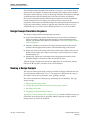
Configuration and Reset . . . . . . . . . . . . . . . . . . . . . . . . . . . . . . . . . . . . . . . . . . . . . . . . . . . . . . . . . . . . . . . . . A–1
Expected Behavior at Initialization . . . . . . . . . . . . . . . . . . . . . . . . . . . . . . . . . . . . . . . . . . . . . . . . . . . . . . . . A–1
Troubleshooting an Interlaken Link . . . . . . . . . . . . . . . . . . . . . . . . . . . . . . . . . . . . . . . . . . . . . . . . . . . . . . . A–2
Appendix B. Excluding Transceivers for Faster Simulation
External Transceiver Interface Clocks . . . . . . . . . . . . . . . . . . . . . . . . . . . . . . . . . . . . . . . . . . . . . . . . . . . . .
External Transceiver Interface Data and Clock Signals . . . . . . . . . . . . . . . . . . . . . . . . . . . . . . . . . . . . . . .
Reset in Interlaken MegaCore Functions Without Transceivers . . . . . . . . . . . . . . . . . . . . . . . . . . . . . . .
Reset Signals . . . . . . . . . . . . . . . . . . . . . . . . . . . . . . . . . . . . . . . . . . . . . . . . . . . . . . . . . . . . . . . . . . . . . . . .
Required Reset Sequence . . . . . . . . . . . . . . . . . . . . . . . . . . . . . . . . . . . . . . . . . . . . . . . . . . . . . . . . . . . . . .
B–2
B–5
B–6
B–7
B–8
Appendix C. Closing Timing on 10- and 20-lane Designs
Appendix D. Porting an Interlaken Design from the Previous Version of the Software
Additional Information
Document Revision History . . . . . . . . . . . . . . . . . . . . . . . . . . . . . . . . . . . . . . . . . . . . . . . . . . . . . . . . . . . Info–1
How to Contact Altera . . . . . . . . . . . . . . . . . . . . . . . . . . . . . . . . . . . . . . . . . . . . . . . . . . . . . . . . . . . . . . . . Info–1
Typographic Conventions . . . . . . . . . . . . . . . . . . . . . . . . . . . . . . . . . . . . . . . . . . . . . . . . . . . . . . . . . . . . . Info–2
June 2012
Altera Corporation
Interlaken MegaCore Function
User Guide
vi
Interlaken MegaCore Function
User Guide
Contents
June 2012 Altera Corporation
1. About This MegaCore Function
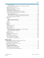
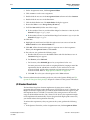
Interlaken is a high-speed serial communication protocol for chip-to-chip packet
transfers. The Altera® Interlaken MegaCore® function implements the Interlaken
Protocol Specification, Revision 1.2. It supports specific combinations of number of lanes
from 4 to 20, and lane rates from 3.125 to 10.3125 gigabits per second (Gbps), on
Stratix® IV GT devices, and lane rates from 3.125 to 6.375 Gbps on Stratix IV GX
devices, providing raw bandwidth of 12.50 Gbps to 127.50 Gbps.
Interlaken provides low I/O count compared to earlier protocols, supporting
scalability in both number of lanes and lane speed. Other key features include flow
control, low overhead framing, and extensive integrity checking. The Interlaken
MegaCore function incorporates a physical coding sublayer (PCS), a physical media
attachment (PMA), and a media access control (MAC) block. The MegaCore function
transmits and receives Avalon® Streaming (Avalon-ST) data on its FPGA fabric
interface.
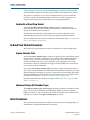
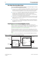
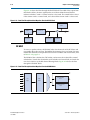
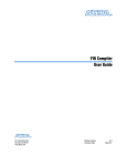
Figure 1–1 shows an example system implementation.
Figure 1–1. Typical Interlaken Application
High-Speed
Memory
Swuitch Fabric or Backplane
Memory
Controller
Interlaken
MegaCore
Function
Stratix IV GX
FPGA
Interlaken Link
Interlaken
MegaCore
Function
Ethernet MAC
Optical
Module
Stratix IV GT
FPGA
Features
The Interlaken MegaCore function has the following features:
June 2012
■
Compliant with the Interlaken Protocol Specification, Rev 1.2
■
Supports 4, 8, 10, 12, and 20 serial lanes in configurations that provide nominal
bandwidths of 20 Gbps, 40 Gbps, and 100 Gbps
■
Supports per-lane data rates of 3.125, 6.25, 6.375, and 10.3125 Gbps using Altera
on-chip high-speed transceivers
Altera Corporation
Interlaken MegaCore Function
User Guide
1–2
Chapter 1: About This MegaCore Function
Device Family Support
■
Supports fast simulation by allowing configuration without high-speed
transceivers
■
Supports up to 127.5 Gbps raw bandwidth
■
Supports dynamically configurable BurstMax and BurstShort values
■
Provides Avalon-ST interfaces on the transmit and receive datapaths
■
Supports two logical channels in out-of-the-box configuration
■
Supports optional user-controlled in-band flow control with 1, 8, or 16 16-bit
calendar pages
■
Supports optional out-of-band flow control blocks for lane status, link status, and
one calendar page
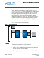
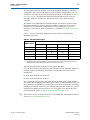
Table 1–1 lists the theoretical raw bandwidth of the Interlaken MegaCore function in
the supported combinations of lane rate and number of lanes.
Table 1–1. Theoretical Raw Aggregate Bandwidth in Gbps
Lane Rate (Gbps)
Number of Lanes
3.125
6.25
6.375
10.3125
4
12.50
25.00
25.50
—
8
25.00
50.00
51.00
—
10
—
62.50
63.75
—
12
—
75.00
76.50
123.75
20
—
125.00
127.50
—
Device Family Support
Table 1–2 defines the device support levels for Altera IP cores.
Table 1–2. Altera IP Core Device Support Levels
FPGA Device Families
HardCopy Device Families
Preliminary support—The core is verified with preliminary
timing models for this device family. The IP core meets all
functional requirements, but might still be undergoing timing
analysis for the device family. It can be used in production
designs with caution.
HardCopy Companion—The IP core is verified with
preliminary timing models for the HardCopy companion
device. The IP core meets all functional requirements, but
might still be undergoing timing analysis for the HardCopy
device family. It can be used in production designs with
caution.
Final support—The IP core is verified with final timing
models for this device family. The IP core meets all
functional and timing requirements for the device family and
can be used in production designs.
HardCopy Compilation—The IP core is verified with final
timing models for the HardCopy device family. The IP core
meets all functional and timing requirements for the device
family and can be used in production designs.
Interlaken MegaCore Function
User Guide
June 2012 Altera Corporation
Chapter 1: About This MegaCore Function
MegaCore Verification
1–3
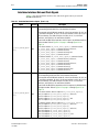
Table 1–3 shows the level of support offered by the Interlaken MegaCore function for
each Altera device family.
Table 1–3. Device Family Support
Device Family
Stratix IV GT
(1)
Support
Final
Stratix IV GX
Final
Note to Table 1–3:
(1) Altera supports the 12-lane, 10-Gbps configuration in Stratix IV GT devices only.
MegaCore Verification
Before releasing a version of the Interlaken MegaCore function, Altera runs
comprehensive regression tests in the current version of the Quartus® II software.
These tests use standalone methods and the Qsys system integration tool to create the
instance files. These files are tested in simulation and hardware to confirm
functionality. Altera tests and verifies the Interlaken MegaCore function in hardware
for different platforms and environments.
Constrained random techniques generate appropriate stimulus for the functional
verification of the MegaCore function. Functional coverage metrics measure the
quality of the random stimulus, and ensure that all important features are verified.
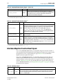
Performance and Resource Utilization
Table 1–4 lists the resources and expected performance for different Interlaken
MegaCore function variations.
Table 1–4 shows results obtained using the Quartus II software for the following
devices:
■
Stratix IV GT device EP4S100G5F45I1
■
Stratix IV GX devices EP4SGX530NF45C2 and EP4SGX530KH40C2
Resource utilization is shown for variations that include the transceiver and do not
include the out-of-band flow control block.
Table 1–4. Interlaken MegaCore Function FPGA Resource Utilization
Parameters
Device
Resource Utilization
Number of
Lanes
Per-Lane Data Rate
(Gbps)
Combinational
ALUTs
Logic Registers
M9K
Blocks
Stratix IV GX
4
6.25
12,229
16,774
52
EP4SGX530NF45C2
8
6.25
24,825
31,776
68
Stratix IV GX
10
6.25
29,949
38,033
96
EP4SGX530KH40C2
20
6.25
63,033
77,806
159
12
10.3125
50,164
56,948
84
Stratix IV GT
EP4S100G5F45I1
June 2012
Altera Corporation
Interlaken MegaCore Function
User Guide
1–4
Chapter 1: About This MegaCore Function
Release Information
For all Interlaken MegaCore function variations that target a Stratix IV GX device,
Altera recommends that you target a C2 speed grade device. For all variations that
target a Stratix IV GT device, Altera recommends you target an I1 speed grade device.
In all cases, Altera recommends that you set the Optimization Technique in the
Analysis & Synthesis Settings dialog box to Speed.
f For information about how to apply the Speed setting, refer to volume 1 of the
Quartus II Handbook.
Release Information
Table 1–5 and Table 1–6 provide information about this release of the Interlaken
MegaCore function. Table 1–5 lists the release information common to all Interlaken
MegaCore function licenses.
Table 1–5. Interlaken MegaCore Function Release Information
Item
Value
Version
12.0
Release Date
June 2012
Vendor ID
6AF7
License Ordering Codes and Product IDs are listed in Table 1–6
Table 1–6 lists the license information for this release of the Interlaken MegaCore
function.
Table 1–6. Interlaken MegaCore Function License Ordering Codes and Product IDs
License (1)
Ordering Code
Product ID
20G License
IP-INTLKN/20G/4L
00DA
40G License
IP-INTLKN/40G/8L
00D5
IP-INTLKN/100G/20L
00D6
IP-INTLKN/100G/12L
00D4
100G Licenses
Note to Table 1–6:
(1) For information about the different licenses, refer to “Interlaken MegaCore Function Licenses” on page 1–5.
Altera verifies that the current version of the Quartus II software compiles the
previous version of each MegaCore function. Any exceptions to this verification are
reported in the MegaCore IP Library Release Notes and Errata. Altera does not verify
compilation with MegaCore function versions older than the previous release.
Installation and Licensing
The Interlaken MegaCore function is part of the MegaCore IP Library, which is
distributed with the Quartus II software and downloadable from the Altera website,
www.altera.com.
Interlaken MegaCore Function
User Guide
June 2012 Altera Corporation
Chapter 1: About This MegaCore Function
Installation and Licensing
1–5
Figure 1–2 shows the directory structure after you install the Interlaken MegaCore
function, where <path> is the installation directory. The default installation directory
on Windows is C:\altera\<version number>; on Linux it is
/opt/altera<version number>.
Figure 1–2. Directory Structure
<path>
Installation directory
ip
Contains the Altera MegaCore IP Library and third-party IP cores
altera
Contains the Altera MegaCore IP Library
common
Contains shared components
alt_interlaken
Contains the Interlaken MegaCore function files
You can use Altera’s free OpenCore evaluation feature to evaluate the MegaCore
function in simulation before you purchase a license. You must purchase a license for
the MegaCore function only when you are satisfied with its functionality, and you
want to check performance in hardware and take your design to production.
After you purchase a license for the Interlaken MegaCore function, you can request a
license file from the Altera website at www.altera.com/licensing and install it on your
computer. When you request a license file, Altera emails you a license.dat file. If you
do not have internet access, contact your local Altera representative.
Interlaken MegaCore Function Licenses
The Altera Interlaken MegaCore function is available to you through several different
licenses, depending on the variation you wish to generate. Licensing is based
primarily on aggregate bandwidth. Table 1–7 shows the license required to program a
device with each supported variation.
Table 1–7. Interlaken MegaCore Function License Support
Lane Rate (Gbps)
Number of
Lanes
3.125
6.25
6.375
10.3125
4
IP-INTLKN/20G/4L
IP-INTLKN/20G/4L
IP-INTLKN/20G/4L
—
8
IP-INTLKN/20G/4L
IP-INTLKN/40G/8L
IP-INTLKN/40G/8L
—
10
—
IP-INTLKN/40G/8L
IP-INTLKN/40G/8L
—
12
—
IP-INTLKN/40G/8L
IP-INTLKN/40G/8L
IP-INTLKN/100G/12L
20
—
IP-INTLKN/100G/20L
IP-INTLKN/100G/20L
—
After you acquire a license, you can compile and program your device with all the
variations that require that license. However, to program a variation that requires a
different license, you must acquire the additional license. You can generate, simulate,
and compile all MegaCore function-supported variations without a license, because
the Interlaken MegaCore function supports the Altera OpenCore evaluation feature.
June 2012
Altera Corporation
Interlaken MegaCore Function
User Guide
1–6
Chapter 1: About This MegaCore Function
Installation and Licensing
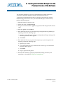
OpenCore Evaluation
The Altera OpenCore evaluation feature allows you to generate RTL files and
simulation models, to simulate, and to compile to validate timing, but requires that
you acquire a license to generate a programming file with which to configure an
FPGA. Therefore, without a license for the variation your design includes, you cannot
create an SRAM Object File (.sof) or Programmer Object File (.pof) for programming a
device with your design. With the free OpenCore evaluation feature, you can perform
the following actions:
■
Simulate the behavior of a megafunction (Altera MegaCore function or AMPPSM
megafunction) in your system using the Quartus II software and Altera-supported
VHDL and Verilog HDL simulators.
■
Verify the functionality of your design and evaluate its size and speed quickly and
easily.
f For more information about installation and licensing, refer to Altera Software
Installation and Licensing.
Interlaken MegaCore Function
User Guide
June 2012 Altera Corporation
2. Getting Started
Design Flows
1
You can customize the Interlaken MegaCore function to support a wide variety of
applications. You use the MegaWizard Plug-In Manager or the Qsys system
integration tool to instantiate this MegaCore function.
The MegaWizard Plug-In Manager flow offers the following advantages:
■
Allows you to parameterize the MegaCore function to create a variation that you
can instantiate manually in your design.
The Qsys flow offers the following advantages:
June 2012
■
Allows you to integrate other Altera-provided custom components such as DMA
controllers, on-chip memories, and FIFOs in your design.
■
Provides visualization of hierarchical designs.
■
Allows customization of interconnect elements and pipelining.
Altera Corporation
Interlaken MegaCore Function
User Guide
2–2
Chapter 2: Getting Started
Design Flows
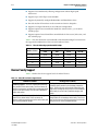
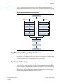
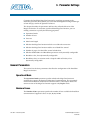
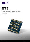
Figure 2–1 shows the stages for creating a system with the Interlaken MegaCore
function and the Quartus II software. Each stage is described in detail in subsequent
sections.
Figure 2–1. Interlaken MegaCore Function Design Flow
Select Design Flow
MegaWizard Plug-in
Manager Flow
Qsys Flow
Specify Parameters
Specify Parameters
Generate
MegaCore Function
Complete Qsys System
Simulate with
Testbench
Generate Qsys System
Instantiate MegaCore
In Design
Simulate System
Specify Constraints
Compile Design
Program Device
MegaWizard Plug-In Manager Design Flow Summary
You can use the MegaWizard Plug-In Manager in the Quartus II software to
parameterize a custom MegaCore function variation. The Interlaken parameter editor
lets you interactively set parameter values and select optional ports. This flow is best
for manual instantiation of a MegaCore function in your design.
Qsys Design Flow Summary
The Qsys design flow enables you to integrate an Interlaken component in a Qsys
system. The Qsys design flow allows you to connect component interfaces with the
system interconnect, eliminating the requirement to design low-level interfaces and
significantly reducing design time. When you add an Interlaken MegaCore function
instance to your design, an Interlaken parameter editor guides you in selecting the
properties of the Interlaken MegaCore function instance.
Interlaken MegaCore Function
User Guide
June 2012 Altera Corporation
Chapter 2: Getting Started
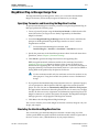
MegaWizard Plug-in Manager Design Flow
2–3
MegaWizard Plug-in Manager Design Flow
The MegaWizard Plug-in Manager flow allows you to customize the Interlaken
MegaCore function, and manually integrate the function in your design.
Specifying Parameters and Generating the MegaCore Function
To specify Interlaken MegaCore function parameters using the MegaWizard Plug-In
Manager, perform the following steps:
1. Create a Quartus II project using the New Project Wizard available from the File
menu. Ensure that you target a device family supported by the Interlaken
MegaCore function.
2. Launch the MegaWizard Plug-in Manager from the Tools menu, and follow the
prompts in the MegaWizard Plug-In Manager interface to create a custom
megafunction variation.
1
To select the Interlaken MegaCore function, click
Installed Plug-Ins > Interfaces > Interlaken > Interlaken v<version>.
3. Specify the parameters in the Interlaken parameter editor. For details about these
parameters, refer to Chapter 3, Parameter Settings.
4. Click Finish to generate the MegaCore function and supporting files.
IEEE encrypted functional simulation models for the simulators listed in the
Simulating Altera Designs chapter in volume 3 of the Quartus II Handbook are
included in the supporting files. The models appear in a set directory hierarchy in
the project directory. The functional simulation model is a cycle-accurate VHDL or
Verilog HDL model produced by the Quartus II software.
c
Use the simulation models only for simulation and not for synthesis or any
other purposes. Using these models for synthesis creates a nonfunctional
design.
5. If you generate the Interlaken MegaCore function instance in a Quartus II project,
you are prompted to add the Quartus II IP File (.qip) to the current Quartus II
project. You can also turn on Automatically add Quartus II IP Files to all projects.
The .qip contains information about the generated IP core. In most cases, the .qip
contains all of the necessary assignments and information required to process the
MegaCore function or system in the Quartus II compiler. The MegaWizard Plug-In
Manager generates a single .qip for each MegaCore function.
6. Click Exit to close the MegaWizard Plug-In Manager.
You can now simulate your custom MegaCore function variation, integrate it in your
design, and compile.
Simulating the Interlaken MegaCore Function
You can simulate your Interlaken MegaCore function variation using any of the
vendor-specific IEEE encrypted functional simulation models which are generated in
the new <instance name>_sim subdirectory of your project directory.
June 2012
Altera Corporation
Interlaken MegaCore Function
User Guide
2–4
Chapter 2: Getting Started
Qsys Design Flow
You cannot simulate the Interlaken MegaCore function in the ModelSim-Altera
(ModelSim-AE) simulator. ModelSim-AE is the simulation tool provided with the
Quartus II software.
f
For Information About
Quartus II software
MegaWizard Plug-In Manager
Functional simulation models for Altera IP
cores
Refer To
See the Quartus II Help topics:
“About the Quartus II Software”
“About the MegaWizard Plug-In Manager”
Simulating Altera Designs chapter in volume 3 of
the Quartus II Handbook
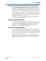
Instantiating the MegaCore Function in Your Design
After you generate your Interlaken MegaCore function variation, you can instantiate
it in the RTL for your design.
When you integrate your Interlaken MegaCore function variation in your design, note
the following connection and assignment requirements and recommendations:
■
If you turn off Exclude transceiver when you parameterize your Interlaken
MegaCore function, you must ensure that you connect the calibration clock
cal_blk_clk to a clock signal with the appropriate frequency range of
10–125 MHz. The cal_blk_clk ports on other components that use the same
transceiver block must be connected to the same clock signal.
■
If you turn off Exclude transceiver when you parameterize your Interlaken
MegaCore function, you should set the RTL parameter SIM_FAST_RESET to 1 to
improve your transceiver simulation time. In this version of the Interlaken
MegaCore function, you must modify your RTL files to set the parameter. Add this
parameter to the parameter list in your HSIO bank instances with the value 1’b1.
The HSIO bank instances for the different variations are instantiations of the
modules alt_ntrlkn_hsio_bank_bpcs4, alt_ntrlkn_hsio_bank_10g,
alt_ntrlkn_hsio_bank_bpcs_3g, or alt_ntrlkn_hsio_bank_pmad5.
Qsys Design Flow
You can use Qsys to build a system that contains your customized Interlaken
MegaCore function. You can easily add other components and quickly create a Qsys
system. Qsys can automatically generate HDL files that include all of the specified
components and interconnections. The HDL files are ready to be compiled by the
Quartus II software to produce output files for programming an Altera device.
Interlaken MegaCore Function
User Guide
June 2012 Altera Corporation
Chapter 2: Getting Started
Qsys Design Flow
2–5
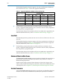
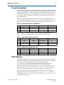
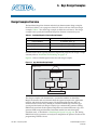
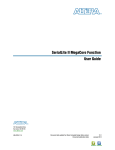
Figure 2–2 shows a block diagram of an example Qsys system.
Figure 2–2. Qsys System
Interlaken
Link Partner
Interlaken
MegaCore Function
Avalon Streaming Connection
Avalon Streaming Connection
Interlaken
Client
Interlaken
Client
System Interconnect
DMA
Controller
On-Chip
FIFO Buffer
On-Chip
Memory
Qsys System
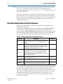
f
For Information About
Refer To
System interconnect
Qsys Interconnect chapter in volume 1 of the Quartus II
Handbook and the Avalon Interface Specifications
Qsys tool
Creating a System with Qsys in volume 1 of the Quartus II
Handbook
Quartus II software
Quartus II Help
Specifying Parameters
To specify Interlaken MegaCore function parameters using the Qsys flow, perform the
following steps:
1. Create a new Quartus II project using the New Project Wizard available from the
File menu.
2. On the Tools menu, click Qsys.
3. On the Component Library tab, expand Interface Protocols > Interlaken and
highlight Interlaken.
4. Click Add to add an Interlaken MegaCore function to your system. The Interlaken
parameter editor appears.
5. Specify the parameters in the Interlaken parameter editor. For detailed
explanations of these parameters, refer to Chapter 3, Parameter Settings.
June 2012
Altera Corporation
Interlaken MegaCore Function
User Guide
2–6
Chapter 2: Getting Started
Qsys Design Flow
6. Click Finish to complete the Interlaken MegaCore function and add it to the
system.
Completing the Qsys System
To complete the Qsys system, perform the following steps:
1. Add and parameterize any additional components.
2. Connect the components using the Connection panel on the System Contents tab.
3. If some signals are not displayed, click the Filter icon to display the Filters dialog
box. In the Filter list, click All Interfaces.
4. Ensure your Qsys system meets the connection and assignment requirements
listed in “Specifying Parameters and Generating the MegaCore Function” on
page 2–3.
5. If you intend to simulate your Qsys system, on the Generation tab, set Generate
simulation model to Verilog to generate a functional simulation model in Verilog
HDL.
6. Click Generate to generate the system. Qsys generates the system and produces a
system .qip file, <system name>.qip, that contains the assignments and information
required to process the IP cores and system in the Quartus II Compiler. The file is
located in the <project name>/synthesis subdirectory.
7. In the Quartus II software, in the Project menu, click Add/Remove Files in Project
and add the
<system name>.qip file to the project.
Simulating the System
During system generation, Qsys optionally generates various IEEE encrypted
functional simulation models for the Interlaken MegaCore function and functional
simulation models for other components in the Qsys system. You can use these
simulation models to simulate your system with your supported simulation tool.
In addition, you can simulate the static design example that is provided in Verilog
HDL. The static design example is available for several Interlaken MegaCore function
variations. Refer to Chapter 6, Qsys Design Examples.
The design examples are located in the design_examples subdirectory of the
alt_interlaken installation directory. Each testbench provides some basic stimulus to
the user interfaces of the Interlaken MegaCore function. You can use the example as a
basis for your own system simulation.
f For information about simulating Qsys systems, refer to the Creating a System with
Qsys chapter in volume 1 of the Quartus II Handbook.
Interlaken MegaCore Function
User Guide
June 2012 Altera Corporation
Chapter 2: Getting Started
Specifying Constraints
2–7
Specifying Constraints
Altera provides a Synopsys Design Constraints (.sdc) file that you must apply to
ensure that the Interlaken MegaCore function meets design timing requirements. The
script automatically constrains the system clocks and the reference clock based on the
data rate you specify. If your design includes multiple instances of the Interlaken
MegaCore function, you must edit the .sdc file to ensure that each instance name
appears correctly in the file.
The Quartus II software v12.0 requires that you add the following additional
constraints manually:
■
Hard PLL Assignment Constraints
■
I/O Standard Constraints
The following sections describe the constraints you must add manually.
Hard PLL Assignment Constraints
The .sdc script provided with the Quartus II software v12.0 requires that you add
hard PLL assignment constraints to the Quartus Settings File (.qsf) before you
compile your design. You can add these constraints directly to the .qsf, or you can use
the Quartus II Assignment Editor.
You must add the following hard transceiver PLL assignments before compilation:
set_location_assignment IOBANK_<quad_location> -to <PLL_path>
where
■
<quad_location> is any valid quad location on your device. It may be any of QLn
or QRn, for n in {0,1,2,3}, depending on the device
■
<PLL_path> is "*|lt_ntrlkn_hsio_bank_*:alt_ilk_hsio_bank_<n>|*|tx_pll*0"
for any valid high-speed I/O (HSIO) bank number <n>
The valid HSIO bank numbers depend on the number of lanes in your Interlaken
MegaCore function variation. Table 2–1 shows the valid HSIO bank numbers.
Table 2–1. Valid HSIO Bank Numbers Depending on Number of Lanes
Valid HSIO Bank Numbers
Number of Lanes
0
1
2
3
4
v
—
—
—
8
v
v
—
—
10
v
v
—
—
12
v
v
v
—
20
v
v
v
v
To add the constraint using the Assignment Editor, perform the following steps:
1. Open your Quartus II project in the Quartus II software.
2. On the Processing menu, point to Start and click Start Analysis & Elaboration.
The analysis and elaboration process might take several minutes to complete.
June 2012
Altera Corporation
Interlaken MegaCore Function
User Guide
2–8
Chapter 2: Getting Started
Specifying Constraints
3. On the Assignments menu, click Assignment Editor.
4. Click <<new>> to edit a new assignment.
5. Double-click the new row in the Assignment Name column and select Location.
6. Double-click the new row in the To column.
7. Click the Node Finder icon. The Node Finder dialog box appears.
8. Ensure that Filter is set to Design Entry (all names).
9. To fill the Named field, follow one of these steps:
■
If the number of lanes in your Interlaken MegaCore function is 10 or 20, in the
Named field, type *tx_pll_edge0
■
If the number of lanes in your Interlaken MegaCore function is 4, 8, or 12, in the
Named field, type *tx_pll0
10. Click List.
11. Highlight each node found and click the right-arrow icon to move it from the
Nodes Found list to the Selected Nodes list.
12. Click OK. All the selected nodes appear in separate rows in the Assignment
Editor, with Assignment Name set to Location.
13. For each new row, perform the following steps:
a. Double-click the new row in the Value column and click the Browse icon. A
Location dialog box appears.
b. For Element, select I/O bank.
c. For Location, select IOBANK_Q<m> for your preferred value <m>.
You must preserve the lane order in assigning IO banks, keeping in mind the
requirement that 10- and 20-lane variations use five transceivers in each
transceiver block, and the other variations use four transceivers in each
transceiver block. Refer to “High-Speed I/O Block” on page 4–22.
d. Click OK. The value you selected appears in the Value column.
f For more information about timing analyzers, refer to the Quartus II Help and The
Quartus II TimeQuest Timing Analyzer chapter in volume 3 of the Quartus II Handbook.
I/O Standard Constraints
The Interlaken MegaCore function implements the transceivers with the
programmable transmitter output buffer power (VCCH TX) set to 1.4 V. Therefore, the
MegaCore function requires that you connect the Interlaken interface signals to pins
that implement the 1.4-V PCML I/O standard. This setting increases the data rate
range of the Interlaken interface. On a Stratix IV GX device, this requirement might
not be implemented automatically. If your design includes high-speed transceivers,
you should enforce this requirement manually.
To enforce this requirement, after you generate the system, perform the following
steps:
1. In the Quartus II window, on the Assignments menu, click Assignment Editor.
Interlaken MegaCore Function
User Guide
June 2012 Altera Corporation
Chapter 2: Getting Started
Compiling the Full Design and Programming the FPGA
2–9
2. For each N, perform the following steps:
a. In the <<new>> cell in the To column, type the top-level signal name for your
Interlaken MegaCore function instance rx_serial_dataN_export signal.
b. Double-click in the Assignment Name column and click I/O Standard.
c. Double-click in the Value column and click 1.4-V PCML.
3. Repeat step 2 for your Interlaken MegaCore function instance
tx_serial_dataN_export signals.
Compiling the Full Design and Programming the FPGA
You can use the Start Compilation command on the Processing menu in the
Quartus II software to compile your design.
The 10- and 20-lane Interlaken MegaCore function variations require fine tuning to
achieve timing closure. Refer to Appendix C, Closing Timing on 10- and 20-lane
Designs for a list of steps you can implement to improve timing.
After successfully compiling your design, program the target Altera device with the
Programmer and verify the design in hardware. Programming the device requires
that you have a license for your Interlaken MegaCore function variation. Refer to
“Interlaken MegaCore Function Licenses” on page 1–5.
f
June 2012
For Information About
Refer To
Compiling your design
Quartus II Incremental Compilation for Hierarchical and TeamBased Design chapter in volume 1 of the Quartus II Handbook
Programming the device
Quartus II Programmer chapter in volume 3 of the Quartus II
Handbook
Altera Corporation
Interlaken MegaCore Function
User Guide
2–10
Interlaken MegaCore Function
User Guide
Chapter 2: Getting Started
Compiling the Full Design and Programming the FPGA
June 2012 Altera Corporation
3. Parameter Settings
Customize the Interlaken MegaCore function by specifying parameters in the
Interlaken parameter editor, which you access from the MegaWizard Plug-In Manager
or from the Qsys tool in the Quartus II software.
This chapter describes the parameters and how they affect the behavior of the
MegaCore function. To customize your Interlaken MegaCore function, you can
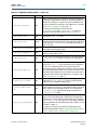
modify parameters to specify the following properties:
■
Operational mode
■
Number of lanes
■
Lane rate
■
Meta frame length
■
Whether the MegaCore function includes or excludes the transceiver
■
Whether the MegaCore function enables out-of-band flow control
■
Number of pages of in-band flow control calendar bits
■
Whether the BurstMax and BurstShort parameters are dynamically configurable
■
BurstMax value, if not dynamically configurable
■
BurstShort value, in variations with a datapath width of 512 bits, if not
dynamically configurable
General Parameters
This section lists the basic parameters that affect the configuration of the Interlaken
MegaCore function.
Operational Mode
The Operational mode parameter specifies whether the MegaCore function is
configured to support simultaneous bidirectional communication. The operational
mode with simultaneous bidirectional communication is called duplex mode. The
current version of the MegaCore function supports only Duplex mode.
Number of Lanes
The Number of lanes parameter specifies the number of lanes available for Interlaken
communication. Supported values are 4, 8, 10, 12, and 20.
June 2012
Altera Corporation
Interlaken MegaCore Function
User Guide
3–2
Chapter 3: Parameter Settings
General Parameters
The Interlaken MegaCore function supports only some combinations of number of
lanes and lane rate. Table 3–1 shows the supported combinations.
Table 3–1. Supported Combinations of Number of Lanes and Lane Rate
Lane Rate (Gbps)
Number of Lanes
1
3.125
6.25
6.375
10.3125
4
v
v
v
—
8
v
v
v
—
10
—
v
v
—
12
—
v
v
v
20
—
v
v
—
The Interlaken parameter editor does not enforce the license restrictions. If you
specify a supported combination that your set of licenses does not allow, compilation
does not generate a programming file.
For information about the lane number and lane rate combinations supported by the
different Interlaken IP licenses, refer to “Installation and Licensing” on page 1–4.
Lane Rate
The Lane rate parameter specifies the data rate on each lane. All lanes have the same
data rate.
The Interlaken MegaCore function supports only certain combinations of number of
lanes and lane rate. Refer to Table 3–1. For information about the device support for
different combinations, refer to Table 1–3 on page 1–3.
1
The Interlaken parameter editor does not enforce the license restrictions. If you
specify a supported combination that your set of licenses does not allow, compilation
does not generate a programming file.
For information about the lane number and lane rate combinations supported by the
different Interlaken IP licenses, refer to “Installation and Licensing” on page 1–4.
Number of Words in Meta Frame
The Meta frame length in words parameter specifies the length of the meta frame, in
64-bit (8-byte) words. In the Interlaken specification, this parameter is called the
MetaFrameLength parameter.
Smaller values for this parameter shorten the time to achieve lock. Larger values
reduce overhead while transfering data, after lock is achieved. For information about
achieving lock, refer to Appendix A, Initializing the Interlaken MegaCore Function.
Exclude Transceiver
Turn on the Exclude transceiver parameter to specify that your Interlaken MegaCore
function does not include an HSIO block. By default, this parameter is turned off.
Interlaken MegaCore Function
User Guide
June 2012 Altera Corporation
Chapter 3: Parameter Settings
In-Band Flow Control Parameters
3–3
If this parameter is turned on, the Interlaken MegaCore function simulation model
and the Interlaken MegaCore function generated RTL both exclude the transceivers.
This option is available to you for faster simulation. However, if you exclude the
transceivers from your Interlaken MegaCore function, you must regenerate and
compile with the parameter turned off to create your programming file.
Enable Out-of-Band Flow Control
Turn on the Enable out-of-band flow control parameter to specify that your
Interlaken MegaCore function includes out-of-band flow control functionality. By
default, this parameter is not turned on.
Turning off out-of-band flow control decreases the resource utilization of your
Interlaken MegaCore function, and excludes this optional specification feature.
For more information about the out-of-band flow control block, refer to “Out-of-Band
Flow Control Block” on page 4–24.
In-Band Flow Control Parameters
This section lists the parameters that affect the in-band flow control configuration.
Expose Calendar Ports
Turn on the Expose calendar ports parameter to specify that the in-band flow control
calendar bits are available on input and output signals of the Interlaken MegaCore
function. If you expose the calendar ports, you are able to view the in-band flow
control RX calendar bits, and you are responsible for specifying the values of the
in-band flow control TX calendar bits that appear in bits [55:40] of the control words
you transmit on the Interlaken link.
If you turn off the Expose calendar ports parameter, a single 16-bit page of in-band
flow control calendar information is included in the Interlaken control words, and the
Interlaken MegaCore function uses only two of those bits. For more information about
the Interlaken MegaCore function behavior when calendar ports are configured and
when they are not, refer to “Calendar and Status Block” on page 4–20.
For information about the calendar port signals, refer to Table 5–6 on page 5–5 and
Table 5–8 on page 5–7.
Number of Sixteen-Bit Calendar Pages
The Width of calendar ports, in 16-bit pages parameter specifies the number of 16-bit
pages of in-band flow control data your Interlaken MegaCore function supports.
Supported values are 1, 8, and 16. You can modify this number from its default value
of 1 only if you turn on the Expose calendar ports parameter.
Burst Parameters
This section lists the parameters that affect the value and dynamic configurability of
the BurstMax and BurstShort Interlaken parameters.
June 2012
Altera Corporation
Interlaken MegaCore Function
User Guide
3–4
Chapter 3: Parameter Settings
Burst Parameters
Enable Dynamic Configuration of BurstMax and BurstShort Parameters
Turn on the Enable dynamic burst parameters parameter to enable dynamic
configuration of the BurstMax and BurstShort Interlaken parameters. If you turn on
this option, your Interlaken MegaCore function has additional input ports you set
dynamically to the desired values of the two Interlaken parameters. Supported values
are BurstMax values of 128 and 256 bytes and BurstShort values of 32 and 64 bytes.
Dynamic configuration of BurstShort is restricted to 12-lane, 10.3125 Gbps and 20-lane
Interlaken MegaCore function variations, that is, the variations with a 512-bit wide
channel datapath. In other variations, whether you turn on Enable dynamic burst
parameters or not, BurstShort has a static value.
Refer to Table 5–8 on page 5–7 for information about the input ports for dynamic
configuration of BurstMax and BurstShort.
Parameterized Static BurstMax Value
If you disable dynamic configuration of the BurstMax and BurstShort parameters, you
can specify the static value of BurstMax that is configured in your Interlaken
MegaCore function with the BURST MAX length in bytes parameter. This parameter
is available if you turn off Enable dynamic burst parameters. Supported static
BurstMax length values are 128 bytes and 256 bytes.
Parameterized Static BurstShort Value
If you turn off Enable dynamic burst parameters, you can specify the static value of
BurstShort that is configured in your 12-lane, 10.3125 Gbps or 20-lane Interlaken
variation. In these Interlaken variations, the default value of the BurstShort Interlaken
parameter is 32 bytes, but you can specify with the BURST SHORT length in bytes
parameter that it be set to 64 bytes instead.
In other Interlaken MegaCore variations, if you turn off Enable dynamic burst
parameters, the static value of BurstShort is 16 bytes in variations with a 128-bit
datapath, and 32 bytes in variations with a 256-bit datapath, as shown in Table 4–1 on
page 4–3.
Interlaken MegaCore Function
User Guide
June 2012 Altera Corporation
4. Functional Description
The Interlaken MegaCore function provides the functionality described in the
Interlaken Protocol Definition, Revision 1.2, and arbitration between two incoming
user-defined channels, and regroups received data to two outgoing user-defined
channels. This chapter describes the individual interfaces and main blocks of the
Interlaken MegaCore function and how data passes between them.
This chapter contains the following sections:
June 2012
■
“Architecture Overview”
■
“Interfaces Overview”
■
“Clocking and Reset Structure” on page 4–5
■
“Transmit Path” on page 4–11
■
“Receive Path” on page 4–17
■
“Calendar and Status Block” on page 4–20
■
“High-Speed I/O Block” on page 4–22
■
“Out-of-Band Flow Control Block” on page 4–24
Altera Corporation
Interlaken MegaCore Function
User Guide
4–2
Chapter 4: Functional Description
Architecture Overview
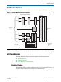
Architecture Overview
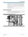
Figure 4–1 shows the main blocks of the Interlaken MegaCore function.
Figure 4–1. Interlaken MegaCore Function Block Diagram
Interlaken MegaCore Function
TX
PCS
Channel 1
Calendar
and
Status
Application
Interface
Channel 0
Packet
Regroup
Filter
and
Buffer
Channel 1
Packet
Regroup
Filter
and
Buffer
RX
MAC
TX Out-of-Band
Flow Control
Calendar and
lane, link status
RX Out-of-Band
Flow Control
RX
PCS
Transceiver Blocks
TX
MAC
Arbiter
FIFO and Pipeline Registers (10- and 20-lane variations only)
Channel 0
HSIO Block
Interlaken
Interface
Out-of-Band
Flow Control
Interface
Out-of-Band Flow Control Block
The following sections describe the individual interfaces, clocks, and blocks.
Interfaces Overview
The Altera Interlaken MegaCore function supports the following interfaces:
■
Interlaken Interface
■
Application Interface
■
Out-of-Band Flow Control Interface
Interlaken Interface
The Interlaken interface complies with the Interlaken Protocol Definition, Revision 1.2. It
provides a high-speed transceiver interface to an Interlaken link.
Interlaken MegaCore Function
User Guide
June 2012 Altera Corporation
Chapter 4: Functional Description
Interfaces Overview
4–3
The Interlaken MegaCore function value for the Interlaken BurstMax parameter is
configurable. You can specify BurstMax to be dynamically configurable or you can
configure a static value in the Interlaken parameter editor, as described in Chapter 3,
Parameter Settings. The Interlaken MegaCore function supports two values for
BurstMax, 128 bytes and 256 bytes. The default static value is 128 bytes for all
variations.
The default value of BurstShort in Interlaken MegaCore function variations with a
512-bit wide datapath is 32 bytes. However, for these variations, you can specify
BurstShort to be dynamically configurable to 32 bytes or 64 bytes, or you can
configure a static value of 32 bytes or 64 bytes, as described in Chapter 3, Parameter
Settings.
Table 4–1 shows the Interlaken MegaCore function values for the Interlaken
BurstShort parameter.
Table 4–1. BurstShort Value in Bytes
Lane Rate (Gbps)
Number of Lanes
3.125
6.25
6.375
10.3125
4
16 (1)
16 (1)
16 (1)
—
8
16 (1)
32
32
—
10
—
32
32
—
12
—
32
32
32 or 64
20
—
32 or 64
32 or 64
—
Note to Table 4–1:
(1) The BurstShort value for Interlaken MegaCore function variations with a 128-bit wide datapath increases link
utilization while preventing multiple burst control words in the same clock cycle.
The Interlaken MegaCore function does not support BurstMin.
If you do not expose the in-band flow control calendar bits, the Interlaken MegaCore
function supports the following in-band flow control format for the RX and TX
calendar bits:
■
Bit 0: XON/XOFF bit for Channel 0
■
Bit 1: XON/XOFF bit for Channel 1
If you expose the calendar ports, the application determines the use of the in-band
flow control bits the MegaCore function receives on the incoming Interlaken link, and
the application is responsible for specifying the values of the in-band flow control bits
the MegaCore function transmits on the outgoing Interlaken link. In this case, you can
configure your MegaCore function to use 1, 8, or 16 pages of 16 calendar bits. For
more information, refer to “Calendar and Status Block” on page 4–20.
f The Interlaken Protocol Definition, Revision 1.2 is available from the Interlaken Alliance
website at www.interlakenalliance.com.
June 2012
Altera Corporation
Interlaken MegaCore Function
User Guide
4–4
Chapter 4: Functional Description
Interfaces Overview
If you turn on the Exclude transceiver parameter to generate a faster simulation
model, your functional simulation model’s interface to and from the Interlaken link
transceivers presents the data in slightly different format and exposes different clocks.
In addition, the application or testbench must implement the reset sequence. For more
information, refer to Appendix B, Excluding Transceivers for Faster Simulation.
Application Interface
The application interface provides two channels of communication to and from the
Interlaken link. Each channel in each direction is implemented as an Avalon-ST
interface with one modification. The width of the Avalon-ST interfaces depends on
the number of lanes in the Interlaken MegaCore function instance.
Depending on the parameter values you set in the Interlaken parameter editor,
additional signals may be available to the application.
Avalon-ST Interface
The Avalon-ST interface provides a standard, flexible, and modular protocol for data
transfers from a source interface to a sink interface. The Avalon-ST interface protocol
allows you to easily connect components to the Interlaken MegaCore function.
The application interface implements an Avalon-ST interface with a modification in
how the empty signal is used and monitored. In the Avalon-ST interface, the empty
signal is monitored only when end-of-packet is asserted. However, the application
interface asserts and monitors this signal during other data-valid clock cycles as well.
This modification allows the application to provide data in incomplete words,
mirroring the same capability on the Interlaken link.
For more information about the application interface, refer to “Arbiter” on page 4–12
and “Packet Regrouper” on page 4–19.
f For more information about the Avalon-ST interface, refer to Avalon Interface
Specifications.
Optional In-Band Flow Control and Dynamic Configuration Signals
Depending on the parameter values you set in the Interlaken parameter editor, the
application interface may include additional signals that the application controls to
dynamically configure the BurstMax and BurstShort signals, or receives and controls
to manage the in-band flow control bits on the Interlaken link. For more infomation
about BurstMax and BurstShort configuration, refer to “Interlaken Interface” and to
Table 5–8 on page 5–7. For more information about the in-band flow control signals,
refer to “Calendar and Status Block” on page 4–20 and to Table 5–6 on page 5–5 and
Table 5–8 on page 5–7.
Out-of-Band Flow Control Interface
The out-of-band flow control interface conforms to the out-of-band requirements in
Section 5.3.4.2, Out-of-Band Flow Control, of the Interlaken Protocol Definition, Revision
1.2. This interface is included in the Interlaken MegaCore function if you turn on the
Enable out-of-band flow control parameter.
For more information, refer to “Out-of-Band Flow Control Block” on page 4–24.
Interlaken MegaCore Function
User Guide
June 2012 Altera Corporation
Chapter 4: Functional Description
Clocking and Reset Structure
4–5
Clocking and Reset Structure
The Interlaken MegaCore function has a variable number of clock domains,
depending on whether the MegaCore function includes or excludes transceivers, and
on whether it includes or excludes the out-of-band flow control block.
In addition to the high-speed clock domains inside the device transceivers, some of
which also clock the PCS lanes, the Interlaken MegaCore function contains two MAC
clock domains for the receive and transmit directions, four out-of-band flow control
block clocks, and clocks for the Interlaken interface.
For information about the clocks visible in your Interlaken IP core functional
simulation model if you turn on Exclude transceivers, refer to Appendix B, Excluding
Transceivers for Faster Simulation.
For recommended clock rates, refer to “Interlaken MegaCore Function Recommended
Clock Rates” on page 4–9.
MegaCore Function MAC Clock Domains
The Interlaken MegaCore function MAC blocks have the following two clock
domains:
■
rx_mac_c_clk—clocks the RX MAC block.
■
tx_mac_c_clk—clocks the TX MAC block.
Altera recommends that the same clock drive the rx_mac_c_clk and tx_mac_c_clk
clocks.
Interlaken Interface Clocks
If you turn off Exclude transceiver, your Interlaken MegaCore function has the
Interlaken interface clocks shown in Table 4–2.
Table 4–2. Interlaken Interface Clocks
Clock Name
Description
ref_clk
Reference clock for the RX and TX transceiver PLLs
cal_blk_clk
Transceiver calibration-block clock
rx_coreclkout
Clocks the RX PCS block. This clock is derived from the physically central RX lane clock.
tx_coreclkout
Clocks the TX PCS block. This clock is derived from the master TX clock from transceiver block 0.
It drives all the transceiver block clk_in clocks, as well as the transmit lanes from the TX PCS
block to the HSIO block.
1
For all Interlaken MegaCore variations except the 8-lane, 3.125-Gbps variation, Altera
recommends that you drive the rx_mac_c_clk and tx_mac_c_clk clocks with the
tx_coreclkout clock. Refer to “Interlaken MegaCore Function Recommended Clock
Rates” on page 4–9.
For information about the Interlaken link facing clocks if you turn on Exclude
transceiver, refer to Appendix B, Excluding Transceivers for Faster Simulation.
June 2012
Altera Corporation
Interlaken MegaCore Function
User Guide
4–6
Chapter 4: Functional Description
Clocking and Reset Structure
Out-of-Band Flow Control Block Clocks
If you turn on Enable out-of-band flow control, your Interlaken MegaCore function
has the following four additional clock domains:
■
rx_oob_in_fc_clk—clocks the incoming out-of-band flow control interface signals
described in the Interlaken specification. This clock is received from an upstream
TX out-of-band flow control block associated with the Interlaken link partner.
■
tx_oob_out_clk—clocks the outgoing out-of-band flow control interface signals
described in the Interlaken specification. This clock is generated by the
out-of-band flow control block and sent to a downstream RX out-of-band flow
control block associated with the Interlaken link partner.
■
rx_oob_in_sys_clk—clocks the outgoing calendar and status information on the
application side of the block. The frequency of this clock must be at least double
the frequency of rx_oob_in_fc_clk.
■
tx_oob_in_double_fc—clocks the incoming calendar and status information on
the application side of the block. The frequency of this clock must be double the
frequency of tx_oob_out_clk.
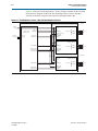
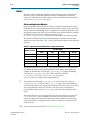
Clock Diagrams for the Interlaken MegaCore Function
Figure 4–2 to Figure 4–6 show the clock diagrams for the Interlaken MegaCore
function variations with the supported numbers of lanes. The figures show variations
with transceivers. For figures that show variations without transceivers, refer to
Appendix B, Excluding Transceivers for Faster Simulation.
The 10-lane and 20-lane variations use the transceivers in PMA Direct mode. These
variations incorporate five lanes in a single transceiver block. The other variations use
the transceivers in low latency PCS mode, incorporating four lanes in each transceiver
block.
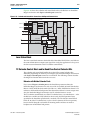
Figure 4–2 shows the clock diagram for a four-lane Interlaken MegaCore function.
Figure 4–2. Clock Diagram for 4-Lane Interlaken MegaCore Function
tx_coreclkout
cal_blk_clk
ref_clk
cal_blk_clk
ref_clk
tx_lane_clk
tx_data [79:0]
TX MAC and PCS
RX MAC and PCS
tx_mac_clk
rx_mac_clk
tx_mac_clk
rx_mac_clk
rx_data [79:0]
rx_lane_clk [3:0]
HSIO Bank 0
(low latency PCS mode)
clk_in
tx_datain[79:0]
tx_pin[3:0]
clk_out (master TX clock)
rx_pin[3:0]
x4
common_rx_clk
rx_dataout[79:0]
rx_clk[3:0]
common_rx_coreclk
rx_coreclkout
Interlaken MegaCore Function
User Guide
June 2012 Altera Corporation
Chapter 4: Functional Description
Clocking and Reset Structure
4–7
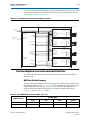
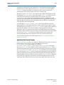
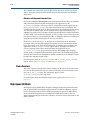
Figure 4–3 shows the clock diagram for an eight-lane Interlaken MegaCore function.
Figure 4–3. Clock Diagram for 8-Lane Interlaken MegaCore Function
tx_coreclkout
cal_blk_clk
ref_clk
cal_blk_clk
ref_clk
TX MAC and PCS
clk_in
tx_datain[79:0]
tx_lane_clk
tx_data [79:0]
HSIO Bank 0
(low latency PCS mode)
tx_pin[3:0]
Lanes 4 to 7
tx_mac_clk
rx_mac_clk
common_rx_clk
rx_dataout[79:0]
rx_clk[3:0]
rx_data [79:0]
rx_lane_clk [3:0]
tx_mac_clk
rx_mac_clk
x4
rx_pin[3:0]
clk_out (master TX clock)
cal_blk_clk
ref_clk
clk_in
tx_datain[79:0]
tx_data [159:80]
HSIO Bank 1
(low latency PCS mode)
tx_pin[3:0]
x4
Lanes 0 to 3
rx_pin[3:0]
RX MAC and PCS
common_rx_clk
rx_dataout[79:0]
rx_clk[3:0]
common_rx_coreclk
rx_data [159:80]
rx_lane_clk [7:4]
rx_coreclkout
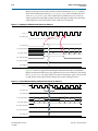
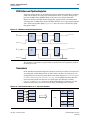
Figure 4–4 shows the clock diagram for a 10-lane Interlaken MegaCore function. This
variation uses the transceivers in PMA Direct mode. For more information, refer to
“High-Speed I/O Block” on page 4–22.
Figure 4–4. Clock Diagram for 10-Lane Interlaken MegaCore Function
tx_coreclkout
cal_blk_clk
ref_clk
TX MAC
and PCS
tx_lane_clk
tx_data[99:0]
rx_data[99:0]
rx_clk[4:0]
tx_mac_c_clk
rx_mac_c_clk
tx_mac_clk
rx_mac_clk
RX MAC
and PCS
tx_data[199:100]
common_rx_coreclk
rx_data[199:100]
rx_clk[9:5]
cal_blk_clk
ref_clk
clk_in
tx_datain[99:0]
clk_out (master TX clock)
common_rx_clk
rx_dataout[99:0]
rx_clk[4:0]
cal_blk_clk
ref_clk
clk_in
tx_datain[99:0]
common_rx_clk
rx_dataout[99:0]
rx_clk[4:0]
HSIO Bank 0
(in PMA Direct mode)
Lanes 5 to 9
tx_pin[4:0]
x5
rx_pin[4:0]
HSIO Bank 1
(in PMA Direct mode)
tx_pin[4:0]
Lanes 0 to 4
x5
rx_pin[4:0]
rx_coreclkout
June 2012
Altera Corporation
Interlaken MegaCore Function
User Guide
4–8
Chapter 4: Functional Description
Clocking and Reset Structure
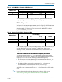
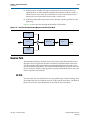
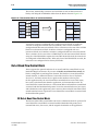
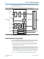
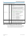
Figure 4–5 shows the clock diagram for a 12-lane, 6-Gbps variation. In this variation,
the transceiver datapath width is 20. The clock diagram for a 12-lane, 10-Gbps
variation is identical, except that the transceiver datapath width is 40.
Figure 4–5. Clock Diagram for 12-Lane, 6-Gbps Interlaken MegaCore Function
tx_coreclkout
cal_blk_clk
ref_clk
cal_blk_clk
ref_clk
TX MAC and PCS
tx_lane_clk
tx_data [79:0]
clk_in
tx_datain[79:0]
RX MAC and PCS
HSIO Bank 0
(low latency PCS mode)
tx_pin[3:0]
Lanes 8 to 11
tx_mac_clk
rx_mac_clk
tx_mac_clk
rx_mac_clk
rx_data [79:0]
rx_lane_clk [3:0]
common_rx_clk
rx_dataout[79:0]
rx_clk[3:0]
cal_blk_clk
ref_clk
tx_data [159:80]
x4
rx_pin[3:0]
clk_out (master TX clock)
clk_in
tx_datain[79:0]
HSIO Bank 1
(low latency PCS mode)
tx_pin[3:0]
Lanes 4 to 7
x4
rx_pin[3:0]
common_rx_coreclk
rx_data [159:80]
rx_lane_clk [7:4]
common_rx_clk
rx_dataout[79:0]
rx_clk[3:0]
rx_coreclkout
cal_blk_clk
ref_clk
tx_data [239:160]
clk_in
tx_datain[79:0]
HSIO Bank 2
(low latency PCS mode)
tx_pin[3:0]
Lanes 0 to 3
x4
rx_pin[3:0]
rx_data [239:160]
rx_lane_clk [11:8]
Interlaken MegaCore Function
User Guide
common_rx_clk
rx_dataout[79:0]
rx_clk[3:0]
June 2012 Altera Corporation
Chapter 4: Functional Description
Clocking and Reset Structure
4–9
Figure 4–6 shows the clock diagram for a 20-lane Interlaken MegaCore function. This
variation uses the transceivers in PMA Direct mode. For more information, refer to
“High-Speed I/O Block” on page 4–22.
Figure 4–6. Clock Diagram for 20-Lane Interlaken MegaCore Function
tx_coreclkout
HSIO Bank 0
cal_blk_clk
(in PMA Direct mode)
ref_clk
clk_in
tx_datain[99:0]
tx_pin[4:0]
clk_out (master TX clock) Lanes 15 to 19
common_rx_clk
rx_pin[4:0]
rx_dataout[99:0]
rx_clk[4:0]
cal_blk_clk
ref_clk
TX MAC
and PCS
tx_lane_clk
tx_data[99:0]
rx_data[99:0]
rx_clk[4:0]
tx_mac_c_clk
rx_mac_c_clk
tx_mac_clk
rx_mac_clk
tx_data[199:100]
cal_blk_clk
ref_clk
clk_in
tx_datain[99:0]
rx_data[199:100]
rx_clk[9:5]
common_rx_clk
rx_dataout[99:0]
rx_clk[4:0]
tx_data[299:200]
cal_blk_clk
ref_clk
clk_in
tx_datain[99:0]
HSIO Bank 1
(in PMA Direct mode)
tx_pin[4:0]
RX MAC
and PCS
tx_data[399:300]
cal_blk_clk
ref_clk
clk_in
tx_datain[99:0]
rx_data[399:300]
rx_clk[19:15]
common_rx_clk
rx_dataout[99:0]
rx_clk[4:0]
x5
Lanes 10 to 14
rx_pin[4:0]
HSIO Bank 2
(in PMA Direct mode)
common_rx_clk
rx_dataout[99:0]
rx_clk[3:0]
common_rx_coreclk
rx_data[299:200]
rx_clk[14:10]
x5
Lanes 5 to 9
tx_pin[4:0]
x5
rx_pin[4:0]
HSIO Bank 3
(in PMA Direct mode)
Lanes 0 to 4
tx_pin[4:0]
x5
rx_pin[4:0]
rx_coreclkout
Interlaken MegaCore Function Recommended Clock Rates
This section describes the recommended frequencies for the Interlaken MegaCore
function clocks.
MAC Clock Verified Frequency
The Altera Interlaken MegaCore function supports the number of lanes and lane rate
combinations shown in Table 3–1 on page 3–2. The verified MAC clock rates for each
variation depend on the lane rate. Table 4–3 shows the MAC clock frequencies at
which the Interlaken MegaCore function was verified. The MAC clocks are the
tx_mac_c_clk and rx_mac_c_clk clocks.
Table 4–3. Verified MAC Block Frequencies in MHz (Part 1 of 2)
Lane Rate (Gbps)
Number of Lanes
June 2012
3.125
6.25
6.375
10.3125
4
156.25
312.50
318.75
—
8
200.00
312.50
318.75
—
Altera Corporation
Interlaken MegaCore Function
User Guide
4–10
Chapter 4: Functional Description
Clocking and Reset Structure
Table 4–3. Verified MAC Block Frequencies in MHz (Part 2 of 2)
Lane Rate (Gbps)
Number of Lanes
10
3.125
6.25
6.375
10.3125
—
312.50
318.75
—
12
—
312.50
318.75
257.81
20
—
312.50
318.75
—
The MAC block must run at an aggregate frequency greater than the PCS block
frequency, to support the overhead of striping and destriping.
PCS Clock Frequencies
The lane rate determines the operating frequency of the TX and RX PCS blocks. For all
variations except the 10.3125-Gbps variation, the PCS frequency is lane rate divided
by 20. For the 10.3125-Gbps variation, because the transceiver datapath width is 40
rather than 20, the PCS frequency is lane rate divided by 40. The PCS clocks are
tx_coreclkout and rx_coreclkout.
Table 4–4. MegaCore Function PCS Block Frequencies in MHz
Lane Rate (Gbps)
Number of Lanes
3.125
6.25
6.375
10.3125
4
156.25
312.50
318.75
—
8
156.25
312.50
318.75
—
10
—
312.50
318.75
—
12
—
312.50
318.75
257.81
20
—
312.50
318.75
—
For all variations except the 8-lane, 3.125-Gbps variation, Altera recommends that you
drive the MAC clocks at the same frequency as the PCS clock. In the 8-lane,
3.125-Gbps variation, the recommended MAC frequency is faster than the PCS
frequency.
Transceiver Reference Clock Recommended Frequency and Source
The transceiver reference clock, ref_clk, is the incoming reference clock for the
Stratix IV GX transceiver’s PLL. To achieve the recommended PCS block operating
frequency, ref_clk must have the following recommended frequency:
■
For all variations except the 10.3125-Gbps variation, the recommended ref_clk
frequency is lane rate divided by 20.
■
For the 10.3125-Gbps variation, the recommended ref_clk frequency is
322.265625 MHz, to achieve the correct lane rate of 10.3125 Gbps.
The ref_clk source affects the jitter performance of the system. For high data rate
applications, your system may require that ref_clk be generated by a GPLL on the
device.
f For more information about driving the transceiver reference clock, refer to
AN580: Achieving Timing Closure in Basic (PMA Direct) Functional Mode.
Interlaken MegaCore Function
User Guide
June 2012 Altera Corporation
Chapter 4: Functional Description
Transmit Path
4–11
For more information about the transceiver reference clock frequency, refer to the
ALTGX Transceiver Setup Guide chapter in volume 3 of the Stratix IV Device Handbook.
For information about high-speed transceiver blocks, refer to volume 2 and volume 3 of
the Stratix IV Device Handbook.
Out-of-Band Flow Control Block Recommended Clock Frequencies
The recommended frequency for the rx_oob_in_fc_clk and the tx_oob_out_clk
clocks is 100 MHz, which is the maximum frequency allowed by the Interlaken
specification.
The rx_oob_in_sys_clk frequency must be at least twice the rx_oob_in_fc_clk
frequency, and the tx_oob_in_double_fc_clk frequency must be twice the
tx_oob_out_clk frequency. In consequence, the recommended frequency for the
rx_oob_in_sys_clk and tx_oob_in_double_fc_clk is 200 MHz.
Reset for Interlaken MegaCore Functions
The Interlaken MegaCore function has a single asynchronous reset, the reset_export
signal. You must assert the reset_export signal for at least four full cal_blk_clk
clock cycles to ensure complete reset of your Interlaken MegaCore function.
Following completion of the reset sequence internally, the Interlaken MegaCore
function begins link initialization. If your Interlaken MegaCore function and its
Interlaken link partner initialize the link successfully, you can observe the assertion of
the lane and link status signals according to the Interlaken specification.
For information about the internal reset sequence that you intiate when you assert the
reset_export signal, refer to “Required Reset Sequence” on page B–8. This section
describes the required reset sequence to reset the full Interlaken MegaCore function,
except the high-speed transceivers. However, the internal reset signals the sequence
drives do not appear as top-level signals in an Interlaken MegaCore function
variation that includes the high-speed transceivers. When you assert the
reset_export signal, this sequence is driven internally and the high-speed
transceivers are reset.
1
Altera recommends that you turn off Global reset in a Qsys system that includes an
Interlaken MegaCore function. Instead, export the reset_export signal and assert it
from outside the Qsys system.
For more information about the link initialization sequence, refer to Table 5–2 on
page 5–3 and to Appendix A, Initializing the Interlaken MegaCore Function.
For more information about the global reset signal, refer to “Interlaken MegaCore
Function Reset Signals” on page 5–4.
Transmit Path
The Interlaken MegaCore function receives application data on two application
channels. It combines the data from the two channels into a single data stream in
which data is labeled with its source channel. The Interlaken TX MAC and PCS blocks
format the data in protocol-compliant bursts and insert Idle words where required.
June 2012
Altera Corporation
Interlaken MegaCore Function
User Guide
4–12
Chapter 4: Functional Description
Transmit Path
Arbiter
The channel arbiter arbitrates between the two incoming channels, channel 0 and
channel 1, using a round-robin arbitration scheme. It implements an Avalon-ST
interface in communication with the channel, with one important modification that
involves the tx_chX_datain_empty signal.
Arbiter and Application Behavior
In the round-robin arbitration scheme, if data is available on both channels and the
Interlaken IP core is not backpressuring either channel, the arbiter accepts data from
the two channels on alternating cycles. The application can enforce full packet mode
operation by forcing each channel to wait until the other channel completes sending a
packet before it asserts its own valid signal. You can use the
tx_control_channel_enable[1:0] bits to selectively disable a channel temporarily.
The channel width depends on the Interlaken MegaCore function variation. Both
channels have the same width. Table 4–5 shows the channel width for each supported
variation.
Table 4–5. Application Channel Width in Bits for Supported Variations
Lane Rate (Gbps)
Number of Lanes
3.125
6.25
6.375
10.3125
4
128
128
128
—
8
128
256
256
—
10
—
256
256
—
12
—
256
256
512
20
—
512
512
—
The arbiter asserts the tx_chX_datain_ready signal to indicate it is ready to receive
new data on channel X. The application indicates to the arbiter that valid data is
available on channel X by asserting the tx_chX_datain_valid signal and holding
valid data on tx_chX_datain_data. The arbiter reads data when both
tx_chX_datain_valid and tx_chX_datain_ready are asserted.
Figure 4–7 shows an example of the required behavior.
1
The application should hold tx_chX_datain_valid and current data values on
tx_chX_datain_data steady for a full tx_mac_c_clk clock cycle in which both the
valid and ready signals are asserted, because otherwise the arbiter does not read this
data. The application need not wait for the ready signal to be asserted before
presenting the initial data to the tx_chX_datain_data bus and asserting the valid
signal.
The channel deasserts its valid signal when it has no more valid data to present on
tx_chX_datain_data. It must maintain the current data on the data bus while it
asserts the valid signal, until one full clock cycle after the arbiter asserts the ready
signal. This behavior is compliant with the Avalon-ST interface specification with
ready latency 0.
f For more information, refer to the Avalon Interface Specifications.
Interlaken MegaCore Function
User Guide
June 2012 Altera Corporation
Chapter 4: Functional Description
Transmit Path
4–13
In addition to incoming data, the arbiter receives start-of-packet and end-of-packet
indicators whose values apply to the data on tx_chX_datain_data in the current
tx_mac_c_clk clock cycle, and an error indicator whose value is valid on the
end-of-packet clock cycle and which refers to the current packet.
The empty vector tx_chX_datain_empty indicates the number of invalid bytes in the
incoming data on tx_chX_datain_data in the current tx_mac_c_clk clock cycle. The
valid data must be in the most significant bytes of the data bus. Use of the
tx_chX_datain_empty signal on non end-of-packet cycles is a modification of the
Avalon-ST interface protocol. This modification allows the application to provide the
Interlaken MegaCore function with incomplete words of valid data, mirroring the
same capability on the Interlaken link.
A two-bit signal, tx_control_channel_enable, allows the application to specify
independently for each channel whether the arbiter should accept or ignore its data.
The application can assert the tx_control_force_transmit signal to tell the arbiter to
ignore the RX calendar value when accepting or ignoring input data from the
application. These two signals provide input to an enable indicator for the channel.
The arbiter sends its interleaved stream of data to the TX MAC block. The information
sent out every tx_mac_c_clk clock cycle includes the data, start-of-packet and
end-of-packet indicators, and an indicator of the source channel for this data.
For more information about the arbiter signals, refer to “TX Application Interface
Signals” on page 5–6.
Application Data Transfer Example
Figure 4–7 to Figure 4–10 show an example of a 1016-byte packet transfer on channel
0. For purposes of the example, assume that channel 1 is not in use
(tx_ch1_datain_valid is not asserted) or is disabled
(tx_control_channel_enable[1:0] has value 1). The tx_coreclkout clock signal
drives the tx_mac_c_clk clock, which is shown in the waveforms. Figure 4–7 shows
the beginning of the packet transfer on channel 0, illustrating the interaction between
the tx_ch0_datain_valid and tx_ch0_datain_ready signal behavior at the beginning
of a packet transfer. Figure 4–8 shows a point partway through the packet transfer, in
which the application is utilizing the Interlaken link fully. The Interlaken MegaCore
function backpressures the channel to prevent overflow. Figure 4–9 shows a different
point partway through the packet transfer, at which the application deasserts the
valid signal when it does not have data ready for the arbiter. This delay causes the
June 2012
Altera Corporation
Interlaken MegaCore Function
User Guide
4–14
Chapter 4: Functional Description
Transmit Path
MegaCore function to insert idle symbols on the Interlaken link. Figure 4–10 shows
the end of the 1016-byte packet on tx_ch0_datain_data, and the resulting non-zero
value of tx_ch0_datain_empty. This example does not illustrate use of a non-zero
empty signal partway through a packet transfer, although the arbiter does check the
empty signal on every clock cycle in which valid data is transfered.
Figure 4–7. Beginning of 1016-Byte Packet Transfer on Channel 0
tx_mac_c_clk
tx_ch0_datain_ready
tx_ch0_datain_valid
tx_ch0_datain_data[127:0]
B0-B15
tx_ch0_datain_empty[3:0]
4h'0
B16-B31
B32-B47
B48-B63
4h'0
4h'0
4h'0
tx_ch0_datain_startofpacket
tx_ch0_datain_endofpacket
tx_ch0_datain_error
Figure 4–8 shows the application utilizing the Interlaken link fully. The Interlaken
MegaCore function backpressures the application to prevent overflow, by deasserting
the tx_ch0_datain_ready signal. When it is ready to accept data again, it reasserts the
tx_ch0_datain_ready signal, and the channel can resume sending new data.
Figure 4–8. Full Link Utilization During 1016-Byte Packet Transfer on Channel 0
tx_mac_c_clk
tx_ch0_datain_ready
tx_ch0_datain_valid
tx_ch0_datain_data[127:0]
tx_ch0_datain_empty[3:0]
4h'0
4h'0
4h'0
4h'0
4h'0
4h'0
4h'0
4h'0
tx_ch0_datain_startofpacket
tx_ch0_datain_endofpacket
tx_ch0_datain_error
Interlaken MegaCore Function
User Guide
June 2012 Altera Corporation
Chapter 4: Functional Description
Transmit Path
4–15
Figure 4–9 shows non-optimal utilization of the Interlaken link. In this case, the
application deasserts its valid signal when it does not have data ready to transfer. As a
result of this gap in incoming data, the Interlaken MegaCore function inserts Idle
symbols on the Interlaken link. In this example, multiple Idle symbols are inserted as
a result of the three cycles in which the application holds the valid signal low.
Figure 4–9. Non-optimal Link Utilization Caused During 1016-Byte Packet Transfer on Channel 0
tx_mac_c_clk
tx_ch0_datain_ready
1
tx_ch0_datain_valid
2
3
tx_ch0_datain_data[127:0]
tx_ch0_datain_empty[3:0]
4h'0
4h'0
4h'0
4h'0
4h'0
4h'0
4h'0
tx_ch0_datain_startofpacket
tx_ch0_datain_endofpacket
tx_ch0_datain_error
Figure 4–10 shows the end of the 1016-byte packet transfer, and the beginning of a
new packet transfer. Because the 1016-byte packet transfer uses only 64 bits of the
final 128-bit application data word on the channel, the tx_ch0_datain_empty signal
has value eight to indicate that the least significant eight bytes in this word are
invalid. Only the eight most significant bytes hold valid data.
Figure 4–10. End of 1016-Byte Packet Transfer and Beginning of New Packet Transfer on Channel 0
tx_mac_c_clk
tx_ch0_datain_ready
tx_ch0_datain_valid
tx_ch0_datain_data[127:0]
tx_ch0_datain_empty[3:0]
4h'0
4h'0
4h'0
B992B1007
B1008B1016
B0-B15
B16-B31
4h'0
4h'8
4h'0
4h'0
4h'0
4h'0
4h'0
tx_ch0_datain_startofpacket
tx_ch0_datain_endofpacket
tx_ch0_datain_error
June 2012
Altera Corporation
Interlaken MegaCore Function
User Guide
4–16
Chapter 4: Functional Description
Transmit Path
TX MAC
The Interlaken MegaCore function TX MAC performs the following functions:
■
Inserts burst and idle control words in the incoming data stream.
■
Repacks the data to ensure the maximum number of words is available on each
valid clock cycle.
■
Calculates and inserts CRC-24 bits in all burst and idle words.
■
Inserts calendar data in all burst and idle words.
■
Stripes the data across the PCS lanes. The MSB of the data goes to lane 0.
■
Buffers data between the application and the TX PCS block in the TX FIFO buffer.
The TX PCS block uses the FIFO buffer to recover bandwidth when the number of
words delivered to the transmitter is less than the full width.
Figure 4–11 shows the flow through the Interlaken TX MAC block.
Figure 4–11. Data Flow Through Interlaken MegaCore Function TX MAC Block
Striping
Burst Control Word
Insertion
Repacking
CRC-24
TX
FIFO
Buffer
To TX PCS Lanes
For more information about the correspondence between lane numbers and output
signals, refer to Table 5–1 on page 5–2.
TX PCS
The Interlaken MegaCore function TX PCS block performs the following functions for
each lane:
■
Inserts the meta frame words in the incoming data stream.
■
Calculates and inserts the CRC-32 bits in the meta frame diagnostic words.
■
Scrambles the data according to the scrambler seed and the protocol-specified
polynomial.
Interlaken MegaCore Function
User Guide
June 2012 Altera Corporation
Chapter 4: Functional Description
Receive Path
4–17
■
Performs 64/67 encoding. The input to this function is 65 bits wide; the most
significant bit is an Altera-defined control bit that indicates whether a word is a
control word or a data word. The control bit has value 1 if the current word is a
control word, and value 0 if the current word is a data word.
■
Performs 67/20 gearboxing. For the 12-lane, 10-Gbps variation, performs 67/40
gearboxing.
Figure 4–12 shows the flow through the Interlaken TX PCS block.
Figure 4–12. Data Flow Through Interlaken MegaCore Function TX PCS Block
Scrambler
CRC-32
64
+
64/67 Encoder
65
Gearbox
67
20 or 40
Framing
Scheduler
Receive Path
The Interlaken MegaCore function receives data on the Interlaken link and sends it
through to the two application channels. The RX PCS and MAC blocks retrieve the
data and calendar information from the incoming Interlaken link and send it out to
two RX channel filtering blocks. The RX channel filtering blocks separate the data for
the two channels, and the packet regroupers regroup each channel’s data in the word
format expected on the channels.
RX PCS
To retrieve the data, the PCS block reverses the gearboxing and 64/67 encoding, then
descrambles the data, and validates the CRC-32 bits and the meta frame. The RX PCS
block also sends lane status information to the calendar and status block.
June 2012
Altera Corporation
Interlaken MegaCore Function
User Guide
4–18
Chapter 4: Functional Description
Receive Path
Figure 4–13 shows the flow through the RX PCS block. The width of the output from
this block is 65 bits; the most significant bit is an Altera-defined control bit that
indicates whether a word is a control word or a data word. The control bit has value 1
if the current word is a control word, and value 0 if the current word is a data word.
Figure 4–13. Data Flow Through Interlaken MegaCore Function RX PCS Block
CRC32
+
67/64 Decoder
Gearbox
20
67
65
Word Aligner
Framing Scheduler
65
Descrambler
RX MAC
To recover a packet or burst, the RX MAC takes data from each of the PCS lanes and
reassembles the packet or burst. The MSB of the incoming data is on lane 0. For more
information about the correspondence between lane numbers and data bit order, refer
to Table 5–1 on page 5–2.
The RX MAC then validates the CRC-24 bits, and recovers the in-band flow control
calendar bits. It sends the calendar bits to the calendar and status block, and sends the
raw data it retrieves to the RX channel filtering blocks. Figure 4–14 shows the flow
through the RX MAC block.
Figure 4–14. Data Flow Through Interlaken MegaCore Function RX MAC Block
Lane Alignment
Lane
Aligner
Destriping
FIFO
Buffer
CRC-24 Validation
Block
Calendar Recovery
Block
Interlaken MegaCore Function
User Guide
June 2012 Altera Corporation
Chapter 4: Functional Description
Receive Path
4–19
Channel Filtering Blocks
Each channel filtering block identifies the data that targets the channel with which it is
associated. It identifies the target channel of a burst from the burst control words. The
channel filtering block passes that data through to a regrouper, filtering out the data
that targets the other channel. As the channel filter filters the data, it rearranges each
data sample so that the valid data and idle bytes for its associated channel are the
most significant bytes.
The following example illustrates the function of the channel filtering blocks in a
variation with a 256-bit channel width. Table 4–6 shows example four-word-wide raw
data output from the RX MAC block. Each table cell represents a 64-bit word.
Table 4–6. Example Raw Data Output From RX MAC Block
t=0
BC SOP ch0
Data 0
Data 1
Data 2
t=1
Data 3
Data 4
BC EOP ch0, SOP ch1
Data 5
t=2
Data 6
Data 7
Data 8
Data 9
t=3
Data 10
Data 11
IDLE EOP ch1
—
Table 4–7 shows the resulting output stream from the RX channel 0 filter and
Table 4–8 shows the resulting output stream from the RX channel 1 filter.
Table 4–7. Output Stream From RX Channel 0 Filter
t’= 0
BC SOP ch0
Data 0
Data 1
Data 2
t’ = 1
Data 3
Data 4
BC EOP ch0
—
t’ = 2
—
—
—
—
t’ = 3
—
—
—
—
Table 4–8. Output Stream From RX Channel 1 Filter
t" = 0
—
—
—
—
t" = 1
BC SOP ch1
Data 5
—
—
t" = 2
Data 6
Data 7
Data 8
Data 9
t" = 3
Data 10
Data 11
IDLE EOP ch1
—
Packet Regrouper
The packet regrouper for each channel receives the filtered data and rearranges each
channel data sample so that the valid bytes are the most significant bytes, removing
all control words. The information is instead conveyed by using the
rx_chX_dataout_empty vector to indicate the number of invalid bytes on the
rx_chX_dataout_data bus in the current rx_mac_c_clk clock cycle. Any
start-of-packet and end-of-packet information is likewise conveyed in separate
signals, rx_chX_dataout_startofpacket and rx_chX_dataout_endofpacket, which
are asserted during the clock cycle in which the appropriate condition holds.
The packet regrouper signals the application channel that it has data ready for
transmission on the channel, by asserting the rx_chX_dataout_valid signal after it
loads the data on the rx_chX_dataout_data bus. Refer to Table 4–5 on page 4–12 for
the channel data bus width.
June 2012
Altera Corporation
Interlaken MegaCore Function
User Guide
4–20
Chapter 4: Functional Description
Calendar and Status Block
The packet regrouper implements an Avalon-ST interface with one important
modification: the rx_chX_dataout_empty vector can indicate the number of invalid
bytes on the rx_chX_dataout_data bus in any rx_mac_c_clk clock cycle in which it
asserts the rx_chX_dataout_valid signal, not just in clock cycles in which it asserts
rx_chX_dataout_endofpacket. This feature supports the transmission of data to the
application interface in the arrangement that most closely reflects the format of this
data on the Interlaken link.
For more information about the RX channel interface signals, refer to “RX Application
Interface Signals” on page 5–5.
Calendar and Status Block
The calendar and status block collects and disseminates in-band calendar information
and lane and link status bits from the RX PCS to the TX path.
Figure 4–15 shows the calendar and status block and its sub-blocks in an Interlaken
MegaCore function with Expose calendar ports turned off.
Figure 4–15. Calendar and Status Block with Hidden Calendar Ports
Interlaken MegaCore Function
Channel 0
data
sop
eop
Channel 1
data
sop
eop
data
Arbiter
channel
sop
TX
PCS
TX
MAC
eop
enable
TX calendar
locked status
RX calendar
Calendar
and
Status
Status
Counters
TX Calendar
Control
HSIO
Block
Lane
Status
crc24_error
RX
MAC
Interlaken MegaCore Function
User Guide
RX
PCS
June 2012 Altera Corporation
Chapter 4: Functional Description
Calendar and Status Block
4–21
Figure 4–16 shows the calendar and status block and its sub-blocks in an Interlaken
MegaCore function with Expose calendar ports turned on.
Figure 4–16. Calendar and Status Block Connections with Exposed Calendar Ports
Interlaken MegaCore Function
data
sop
eop
Channel 0
data
Arbiter
sop
data
sop
eop
Channel 1
channel
TX
PCS
TX
MAC
eop
enable
TX calendar
TX calendar
locked status
RX calendar
Calendar
and
Status
TX Calendar
Control
Status
Counters
HSIO
Block
Lane
Status
crc24_error
RX
MAC
RX
PCS
Lane Status Block
The lane status block monitors the health of the Interlaken RX PCS lanes and delivers
the status information to output status signals for use by the application. It also passes
the lane status information to the TX calendar control block.
TX Calendar Control Block and In-Band Flow Control Calendar Bits
The calendar and status block handles the in-band flow control calendar bits
differently, depending on whether you configure your Interlaken MegaCore function
with Expose calendar ports turned on or turned off. The following sections describe
the MegaCore function behavior in the two cases.
Behavior with Hidden Calendar Ports
If you turn off Expose calendar ports in the Interlaken parameter editor, the
Interlaken MegaCore function uses only two of the 16 available in-band calendar bits.
Bit 0 is a XON/XOFF bit for channel 0, and bit 1 is a XON/XOFF bit for channel 1. To
indicate to the Interlaken link partner that channel 0 or channel 1 cannot accept more
data, the Interlaken MegaCore function sets TX calendar bit 0 or 1 to zero.
The TX calendar control block sets all the TX calendar bits to 1 at initialization — after
the RX lanes and link are fully locked (in other words, the RX Operational state
specified in the Interlaken specification is reached). The TX calendar control block
holds all 16 of the TX calendar bits at value 1 for the duration of IP core operation,
because the RX datapath can handle all incoming traffic and does not need to
backpressure its Interlaken link partner.
June 2012
Altera Corporation
Interlaken MegaCore Function
User Guide
4–22
Chapter 4: Functional Description
High-Speed I/O Block
The calendar and status block sends the RX calendar bits to the enable logic for the
arbiter. These bits contain the XON/XOFF status for the channels in the Interlaken
link partner.
Behavior with Exposed Calendar Ports
If you turn on Expose calendar ports in the Interlaken parameter editor, the calendar
and status block provides the RX calendar bits to the application on the
rx_status_calendar bus, and receives the TX calendar bits from the application on
the tx_control_status_calendar bus rather than from the lane status block. The
calendar and status block sends the RX calendar bits to the enable logic for the arbiter,
as it does when calendar ports are not exposed, but the application controls any
additional use of these bits. The arbiter enable logic interprets RX calendar bits 0 and 1
as XON/XOFF status for the two channels, exactly as it does when calendar ports are
not exposed. However, you can modify the RTL to change this behavior, in addition to
using the exposed RX calendar ports in any way you choose.
In this case, you can specify 1, 8, or 16 pages of 16 calendar bits in the Interlaken
parameter editor. The Interlaken MegaCore function receives in-band flow control
bits in the control words from the Interlaken link, and makes them available to the
application on the rx_status_calendar output signals. The MegaCore function
receives outgoing in-band flow control bits from the application on the
tx_control_tx_calendar signal, and inserts them in bits [55:40] of the outgoing
control words, as required by the Interlaken specification. The Interlaken MegaCore
function does not insert any in-band flow control calendar bits in the multiple-use bits
[31:24] of the outgoing control words.
For information about the rx_status_calendar and tx_control_status_calendar
signals, refer to Table 5–6 on page 5–5 and Table 5–8 on page 5–7.
Status Counters
The status counters count the time and the number of CRC-24 errors encountered so
far since the RX Operational state was achieved. The time counter increments every
318 × 106 rx_mac_c_clk cycles. The locked time appears on the
rx_status_locked_time status signal bus.
For information about the individual output status signals, refer to Table 5–2 on
page 5–3.
High-Speed I/O Block
The high-speed I/O (HSIO) block comprises multiple ALTGX megafunction blocks
and an optional FIFO and pipeline registers block. The FIFO and pipeline registers
block is instantiated only when the ALTGX megafunction operates in PMA Direct
mode. The ALTGX megafunction is configured in PMA Direct mode in 10- and
20-lane Interlaken MegaCore function variations, and in low latency PCS mode in the
other variations.
Interlaken MegaCore Function
User Guide
June 2012 Altera Corporation
Chapter 4: Functional Description
High-Speed I/O Block
4–23
FIFO Buffers and Pipeline Registers
Achieving timing closure can be difficult for the 10- and 20-lane Interlaken variations,
which use the Stratix IV transceivers in PMA Direct mode. To resolve timing issues
between the PMA Direct SERDES block in the transceiver and the Interlaken
MegaCore function, the FIFO buffer and pipeline registers block is instantiated for
variations that use PMA Direct mode. The block includes a two-stage register pipeline
and a clock-crossing FIFO buffer. Figure 4–17 shows the receive and transmit paths
through this block.
Figure 4–17. FIFO Buffer and Pipeline Registers Block
From
TX PCS Block
To TX Transceiver
FIFO
Buffer
tx_clkout (PCLK)
GCLK from core
To
RX PCS Block
From RX Transceiver
FIFO
Buffer
rx _clkout (PCLK)
GCLK from core
The pipelines are clocked by a global clock on the PCS side and a periphery clock on
the transceiver side.
Transceivers
In 10- and 20-lane Interlaken MegaCore function variations, the Stratix IV transceivers
are configured in PMA Direct mode. In all the other variations, the transceivers are
configured in low latency PCS mode. Refer to the clock diagrams in “Clock Diagrams
for the Interlaken MegaCore Function” on page 4–6 for information about how the
transceiver bank clock and data lines are connected in the different variations.
Figure 4–18 and Figure 4–19 show how the Interlaken MegaCore function uses the
individual transceivers in each transceiver block, depending on the variation.
Figure 4–18. Transceiver Block Use in 4-, 8-, and 12-lane Variations
20
lane
ALTGX
PCS
PMA
ALTGX
PCS
PMA
20
lane
20
ALTGX
lane
20
lane
June 2012
Altera Corporation
PMA
FPGA
ALTGX
PMA
PCS
PMA
PCS
PMA
Interlaken MegaCore Function
User Guide
4–24
Chapter 4: Functional Description
Out-of-Band Flow Control Block
The 12-lane, 10.3125-Gbps variations use four PMAs in each of three transceiver
blocks, with datapath width 40 bits rather than the 20 bits shown in Figure 4–18.
Figure 4–19. Transceiver Block Use in 10- and 20-lane Variations
20
lane
ALTGX
PCS
PMA
ALTGX
PCS
PMA
20
lane
20
ALTGX
lane
20
PMA
FPGA
ALTGX
lane
PMA
20
ALTGX
lane
PCS
PMA
PCS
PMA
A four-lane variation is configured with a single transceiver block, an eight-lane
variation is configured with two transceiver blocks, and a 12-lane variation is
configured with three transceiver blocks. These variations use four out of the six PMA
blocks in each transceiver block. A 10-lane variation is configured with two
transceiver blocks, and a 20-lane variation is configured with four transceiver blocks.
These variations use five out of the six PMA blocks in each transceiver block. Because
using five of the PMA blocks requires that one CMU channel be used, the transceivers
are configured in PMA Direct mode. When only four of the PMA blocks are used, the
transceivers are configured in low latency PCS mode.
Out-of-Band Flow Control Block
Altera supports the optional inclusion of an out-of-band flow control block in your
Interlaken MegaCore function. If you turn on Enable out-of-band flow control, the
block is configured in your MegaCore function. The block has an out-of-band flow
control interface, as defined in Section 5.3.4.2 of the Interlaken Protocol Definition,
Revision 1.2. You must connect the six signals in this interface to device pins.
On the application side, the out-of-band flow control block can receive link status,
lane status, and calendar bits from the application, and transmit them on the TX
out-of-band flow control interface to a downstream RX out-of-band flow control block
associated with the Interlaken link partner. It can also transmit link status, lane status,
and calendar bits to the application, after it receives them on the RX out-of-band flow
control interface from an upstream TX out-of-band flow control block associated with
the Interlaken link partner.
RX Out-of-Band Flow Control Block
The RX out-of-band flow control block can receive calendar bits from an upstream TX
out-of-band flow control block associated with the Interlaken link partner, and
transmit link status, lane status, and the original calendar bits to the application.
Interlaken MegaCore Function
User Guide
June 2012 Altera Corporation
Chapter 4: Functional Description
Out-of-Band Flow Control Block
4–25
TX Out-of-Band Flow Control Block
The TX out-of-band flow control block can receive link status, lane status, and
calendar bits from the application, and transmit them on the TX out-of-band flow
control interface to a downstream RX out-of-band flow control block associated with
the Interlaken link partner.
Out-of-Band Flow Control Block Signals
Figure 4–20 shows the out-of-band flow control block.
Figure 4–20. Out-of-Band Flow Control Block
Calendar and
lane, link status
TX Out-of-Band
Flow Control
RX Out-of-Band
Flow Control
tx_oob_out_clk,
tx_oob_out_sync,
tx_oob_out_data
rx_oob_in_fc_clk,
rx_oob_in_fc_sync,
rx_oob_in_fc_data
Out-of-Band
Flow Control
Interface
Out-of-Band Flow Control Block
For clock constraints and comprehensive information about the signals of this block,
refer to “Out-of-Band Flow Control Interface Signals” on page 5–8.
June 2012
Altera Corporation
Interlaken MegaCore Function
User Guide
4–26
Interlaken MegaCore Function
User Guide
Chapter 4: Functional Description
Out-of-Band Flow Control Block
June 2012 Altera Corporation
5. Signals
This chapter describes the Interlaken MegaCore function signals.
1
Qsys allows you to export signals with different names or prefixes. Refer to the Qsys
System Contents tab for the signals that support this capability, and to the Qsys HDL
Example tab for the list of signals that are exported with predefined names. The
default prefix for a newly exported signal is the MegaCore function instance name in
the Qsys system. However, you can overwrite the name with which any signal is
exported. After you export a signal, it is added in the HDL Example tab with the
name you specify.
Interlaken Interface and External Transceiver Interface Signals
Table 5–1 through Table 5–3 list the pins related to the Interlaken interface of the
Interlaken MegaCore function. If you turn off Exclude transceivers, your Interlaken
MegaCore function includes high-speed transceivers. Table 5–1 lists the Interlaken
interface data signals in that case.
If you turn on Exclude transceivers, your Interlaken MegaCore function does not
include high-speed transceivers. In that case, the data for the Interlaken link appears
on the external transceiver interface. Table B–1 on page B–5 lists the external
transceiver interface signals.
Table 5–2 and Table 5–3 describe the Interlaken interface status signals. These signals
are available whether or not you turn on Exclude transceivers.
June 2012
Altera Corporation
Interlaken MegaCore Function
User Guide
5–2
Chapter 5: Signals
Interlaken Interface and External Transceiver Interface Signals
Interlaken Interface Data and Clock Signals
Table 5–1 lists the Interlaken interface data and clock signals when you turn off
Exclude transceivers.
Table 5–1. Interlaken Data Interface Signals (Part 1 of 2)
Signal
Direction
Description
Differential high-speed serial input data to the transceiver. It is connected to the
corresponding transmit data lines of the Interlaken link partner.
N corresponds to the HSIO bank number. N = 0 for 4-lane variations; N = {0,1} for
8- and 10-lane variations, N = {0,1,2} for 12-lane variations, and N = {0,1,2,3} for
20-lane variations. The width of the port is 4 (M=3) for 4-, 8-, and 12-lane
variations, and 5 (M=4) for 10- and 20-lane variations.
Lane 0 holds the MSB of the input data, which is input to the HSIO bank with the
highest number. Refer to Figure 4–2 on page 4–6 through Figure 4–6 on
page 4–9.
rx_serial_dataN_export
Input
[M:0]
In an 8-lane variation, rx_serial_data1_export[3] connects to lane 0,
rx_serial_data1_export[2] connects to lane 1, and so on;
rx_serial_data0_export[2] connects to lane 5,
rx_serial_data0_export[1] connects to lane 6, and
rx_serial_data0_export[0] connects to lane 7.
In a 20-lane variation, rx_serial_data3_export[4] connects to lane 0,
rx_serial_data3_export[3] connects to lane 1, and so on;
rx_serial_data2_export[4] connects to lane 5,
rx_serial_data2_export[3] connects to lane 6, and so on;
rx_serial_data1_export[4] connects to lane 10;
rx_serial_data1_export[0] connects to lane 14;
rx_serial_data0_export[4] connects to lane 15, and
rx_serial_data0_export[0] connects to lane 19.
Differential high-speed serial output data from the transceiver. It is connected to
the corresponding receive data lines of the Interlaken link partner.
N corresponds to the HSIO bank number. N = 0 for 4-lane variations; N = {0,1} for
8- and 10-lane variations, N = {0,1,2} for 12-lane variations, and N = {0,1,2,3} for
20-lane variations. The width of the port is 4 (M=3) for 4-, 8-, and 12-lane
variations, and 5 (M=4) for 10- and 20-lane variations.
Lane 0 holds the MSB of the output data, which is output on the HSIO bank with
the highest number. Refer to Figure 4–2 on page 4–6 through Figure 4–6 on
page 4–9.
tx_serial_dataN_export
Input
[M:0]
In an 8-lane variation, lane 0 is output on tx_serial_data1_export[3],
lane 1 is output on tx_serial_data1_export[2], and so on;
lane 5 is output on tx_serial_data0_export[2],
lane 6 is output on tx_serial_data0_export[1], and
lane 7 is output on tx_serial_data0_export[0].
In a 20-lane variation, lane 0 is output on tx_serial_data3_export[4],
lane 1 is output on tx_serial_data3_export[3], and so on;
lane 5 is output on tx_serial_data2_export[4],
lane 6 is output on tx_serial_data2_export[3], and so on;
lane 10 is output on tx_serial_data1_export[4];
lane 14 is output on tx_serial_data1_export[0];
lane 15 is output on tx_serial_data0_export[4], and
lane 19 is output on tx_serial_data0_export[0].
Interlaken MegaCore Function
User Guide
June 2012 Altera Corporation
Chapter 5: Signals
Interlaken Interface and External Transceiver Interface Signals
5–3
Table 5–1. Interlaken Data Interface Signals (Part 2 of 2)
Signal
Direction
Description
Input
Main transceiver reference clock. Refer to “Transceiver Reference Clock
Recommended Frequency and Source” on page 4–10.
cal_blk_clk
Input
Calibration clock for transceiver on-chip termination resistors. The Stratix IV GX
transceiver on-chip termination resistors are calibrated by a single calibration
block, which requires a calibration clock. The frequency range of cal_blk_clk
is 10–125 MHz. For more information, refer to the Stratix IV Transceiver
Architecture chapter in volume 2 of the Stratix IV Device Handbook.
tx_coreclkout
Output
Master TX clock from transceiver block 0. Clocks the transmit lanes of all
transceiver blocks internally.
rx_coreclkout
Output
The physically central clock from among the rx_clk clocks output from the
transceiver blocks. Drives the common_rx_clk input clock to all transceiver
blocks internally. You can use this clock to drive the rx_mac_c_clk input clock.
ref_clk
Interlaken Interface Status Signals
Table 5–2 and Table 5–3 describe the Interlaken interface status signals. These signals
are available whether or not you turn on Exclude transceivers.
Table 5–2. Interlaken RX Status Interface Signals
Signal
Direction
(1)
(Part 1 of 2)
Description
Output
Indicates lane has locked onto the three-bit synchronization header.
(Sixty-four consecutive legal sync patterns have been observed;
64B/67B Word Lock, in the Interlaken specification). This signal is
deasserted when lane word lock is lost according to the Interlaken
specification. Width is the number of lanes (L = num_lanes – 1).
rx_status_per_lane_sync_lock
[L:0]
Output
Indicates lane has locked onto the meta frame boundary and recovered
the scrambler seed from incoming traffic. (Rx LaneValid in the
Interlaken specification). This signal is deasserted when sync lock is
lost according to the Interlaken specification. Width is the number of
lanes (L = num_lanes – 1).
rx_status_all_word_locked
Output
Indicates all lanes are word-locked.
rx_status_all_sync_locked
Output
Indicates all lanes are sync-locked.
rx_status_fully_locked
Output
Indicates the Interlaken receiver is fully locked. This signal is asserted
when rx_status_all_word_locked is high,
rx_status_all_sync_locked is high, and lane alignment is
complete. (RX Operational, in the Interlaken specification). The signal is
deasserted when any of these three conditions no longer holds,
according to the Interlaken specification.
rx_status_locked_time[15:0]
Output
Counter that tracks the time elapsed since rx_status_fully_locked
is asserted. Increments once every 318 × 106 rx_mac_c_clk cycles.
rx_status_error_count[15:0]
Output
Counter that tracks the number of CRC-24 errors encountered.
rx_status_per_lane_word_lock
[L:0]
rx_status_per_lane_crc32_errs
Output
[Q:0]
June 2012
Altera Corporation
Per-lane, 8-bit counters for tracking the number of CRC-32 errors
encountered. Width is 8 × num_lanes. (Q = 8 × num_lanes – 1).
Bits[7:0] track the CRC-32 errors on RX lane 0, bits [15:8] track the
CRC-32 errors on RX lane 1, and so on.
Interlaken MegaCore Function
User Guide
5–4
Chapter 5: Signals
Interlaken MegaCore Function Reset Signals
Table 5–2. Interlaken RX Status Interface Signals
Signal
(1)
(Part 2 of 2)
Direction
Output
rx_status_overflow
Description
Indicates that the RX MAC and channel filter blocks are unable to
process data as fast as it arrives on the Interlaken link, and data is lost
or corrupted. You can use the out-of-band flow control block to
backpressure the Interlaken link partner.
Note to Table 5–2:
(1) All of the RX status signals are clocked by rx_mac_c_clk.
Table 5–3. Interlaken TX Status Interface Signals
Signal
(1)
Direction
Description
tx_status_hungry
Output
Indicates that the TX FIFO in the MAC TX block is close to underflow. By default,
the Interlaken MegaCore function has TX underflow protection enabled, and the
TX FIFO cannot actually underflow: in response to a near-underflow condition,
the PCS TX block inserts IDLE words in the outgoing data stream (on
tx_serial_dataN_export or tx_dataN_export). The application can
monitor or ignore this signal. The signal warns the monitoring application that
data density on the incoming channels is not ideal.
tx_status_overflow
Output
Indicates that the TX FIFO in the MAX TX block has overflowed. Data has been
lost or corrupted.
Output
Indicates that the TX FIFO in the MAC TX block has underflowed. By default, this
condition cannot occur. The Interlaken MegaCore function has TX underflow
protection enabled, and the TX FIFO cannot actually underflow: in response to a
near-underflow condition, indicated by tx_status_hungry, the PCS TX block
inserts IDLE words in the outgoing data stream (on tx_serial_dataN_export
or tx_dataN_export).
tx_status_underflow
Note to Table 5–3:
(1) All of the TX status signals are clocked by tx_mac_c_clk.
Interlaken MegaCore Function Reset Signals
If you turn off Exclude transceivers, your Interlaken MegaCore function includes a
reset controller block that implements the full MegaCore function reset sequence after
the application asserts a single global reset signal. Table 5–4 lists the Interlaken
MegaCore function global reset signal.
If you turn on Exclude transceivers, your Interlaken MegaCore function does not
include a reset controller. In that case, you must control multiple reset signals for
individual blocks to enforce the correct reset sequence for the Interlaken MegaCore
function. Table B–2 on page B–7 lists the individual reset signals visible when you
turn on Exclude transceivers, and “Required Reset Sequence” on page B–8 describes
the required reset sequence.
Table 5–4. Global Reset Signal
Signal
reset_export
Direction
Description
Input
Asynchronous reset for the full Interlaken MegaCore function, including the RX and TX MAC
blocks, the full TX FIFO, the RX and TX PCS blocks, and the transceivers. This reset signal
can be asserted and deasserted asynchronously, but must remain asserted at least four
cal_blk_clk clock cycles.
Interlaken MegaCore Function
User Guide
June 2012 Altera Corporation
Chapter 5: Signals
Application Interface Signals
5–5
Application Interface Signals
The application interface provides two channels through which the application
receives data from and sends data to the Interlaken link. Table 5–5 through Table 5–8
describe the application interface signals.
RX Application Interface Signals
The RX application interface provides two channels through which the application
receives data from the Interlaken link.
Table 5–5 and Table 5–6 describe the RX application interface signals. For more
information about these signals, refer to “Packet Regrouper” on page 4–19.
Table 5–5. RX Application Interface Clock Signal
Signal
Direction
Description
Clocks the Interlaken MegaCore function MAC RX block and therefore, also, the RX
application interface.
rx_mac_c_clk
Input
For all MegaCore function variations except the 8-lane, 3.125-Gbps variations, Altera
recommends that you drive this signal with the tx_coreclkout signal (in variations with
transceivers), or that you drive this signal with the same clock that drives the
tx_lane_c_clk signal (in variations without transceivers).
For the 8-lane, 3.125-Gbps variations, the rx_mac_c_clk clock should be driven by a
faster clock than the RX PCS clock. For these variations, Altera recommends that
rx_mac_c_clk be driven by the same clock that drives the tx_mac_c_clk. For
recommended frequencies, refer to “Interlaken MegaCore Function Recommended Clock
Rates” on page 4–9.
Table 5–6. RX Application Data Interface Signals
Signal
Direction
(1)
(Part 1 of 2)
Description
rx_chX_dataout_data[W:0]
Output
Channel X data out. Streams the data received on the Interlaken interface
out on channel X. Width is 128 bits for variations that require the 20G/4L
license, 256 bits for variations that require the 40G/8L license, and 512
for variations that require one of the 100G licenses. For details, refer to
Table 4–5 on page 4–12. (W = width – 1).
rx_chX_dataout_valid
Output
Indicates data out on the current channel (rx_chX_dataout_data) is
valid in the current rx_mac_c_clk cycle.
rx_chX_dataout_startofpacket Output
Indicates data out on the current channel in the current rx_mac_c_clk
cycle includes a start-of-packet.
rx_chX_dataout_endofpacket
Output
Indicates data out on current channel in the current rx_mac_c_clk
cycle includes an end-of-packet.
rx_chX_dataout_error
Output
Indicates an error occurred during transmission of the current packet on
rx_chX_datain_data. This signal is valid only in an end-of-packet
cycle.
June 2012
Altera Corporation
Interlaken MegaCore Function
User Guide
5–6
Chapter 5: Signals
Application Interface Signals
Table 5–6. RX Application Data Interface Signals
Signal
(1)
(Part 2 of 2)
Direction
rx_chX_dataout_empty[T:0]
rx_status_calendar[P:0]
Output
Output
Description
Indicates the number of invalid bytes on the rx_chX_dataout_data
bus in the current rx_mac_c_clk cycle, starting from the least
significant byte. The value 1 indicates that bits [7:0] are invalid; the value
2 indicates bits [15:0] are invalid, and so on. Width is 4 bits for
variations with a 128-bit wide channel (20G/4L license), 5 bits for
variations with a 256-bit wide channel (40G/8L license), and 6 bits for
variations with a 512-bit wide channel (either of the 100G licenses). For
details, refer to Table 4–5 on page 4–12. (T = width – 1).
RX calendar bits from the recent incoming Interlaken link control
word(s). Each 16-bit calendar page is transferred from the upstream
Interlaken partner in bits [55:40] of a single control word. The width of
the rx_status_calendar signal is 16 × the number of calendar pages
you specified in the Interlaken parameter editor. (width is 16, 128, or 256
bits; P = width – 1).
This signal is present only if you expose the calendar pages in the
Interlaken parameter editor. Refer to “In-Band Flow Control Parameters”
on page 3–3 and “Calendar and Status Block” on page 4–20.
Note to Table 5–6:
(1) The Interlaken MegaCore function supports two channels on the application interface. The string “chX” in a signal name indicates two distinct
signal names, one with “ch0” and one with “ch1”, corresponding to the two channels, channel 0 and channel 1.
TX Application Interface Signals
The TX application interface provides two channels through which the application
sends data to the Interlaken link.
Table 5–7 and Table 5–8 describe the TX application interface signals. For more
information about these signals, refer to “Arbiter” on page 4–12.
Table 5–7. TX Application Interface Clock Signal
Signal
Direction
Description
Clocks the Interlaken MegaCore function MAC TX block and therefore, also, the TX
application interface.
tx_mac_c_clk
Input
For all MegaCore function variations except the 8-lane, 3.125-Gbps variations, Altera
recommends that you drive this signal with the tx_coreclkout signal (in variations with
transceivers), or that you drive this signal with the same clock that drives the
tx_lane_c_clk signal (in variations without transceivers).
For the 8-lane, 3.125-Gbps variations, the tx_mac_c_clk clock should be driven by a
faster clock than the TX PCS clock. For these variations, Altera recommends that
tx_mac_c_clk be driven by the same clock that drives the rx_mac_c_clk. For
recommended frequencies, refer to “Interlaken MegaCore Function Recommended Clock
Rates” on page 4–9.
Interlaken MegaCore Function
User Guide
June 2012 Altera Corporation
Chapter 5: Signals
Application Interface Signals
5–7
Table 5–8. TX Application Interface SIgnals
Signal
tx_chX_datain_data[W:0]
(1)
Direction
Input
(Part 1 of 2)
Description
Channel X data in. Streams in the channel X data to be transmitted on
the Interlaken interface. Width is 128 bits for variations that require the
20G/4L license, 256 bits for variations that require the 40G/8L license,
and 512 for variations that require one of the 100G licenses. For details,
refer to Table 4–5 on page 4–12. (W = width – 1).
The arbiter reads data from this bus when both the
tx_chX_datain_valid and tx_chX_datain_ready signals are
asserted. For more information, refer to “Arbiter” on page 4–12.
Input
Indicates data in on the current channel (tx_chX_datain_data) is valid
in the current tx_mac_c_clk cycle.
tx_chX_datain_ready
Output
Indicates the arbiter is ready to receive data on channel X. This signal is
the Avalon-ST protocol ready output flag. The input data stream for the
current channel (tx_chX_datain_data) is backpressured until this
signal is asserted.
tx_chX_datain_startofpacket
Input
Indicates data in on the current channel in the current tx_mac_c_clk
cycle includes a start-of-packet symbol.
tx_chX_datain_endofpacket
Input
Indicates data in on current channel in the current tx_mac_c_clk cycle
includes an end-of-packet symbol.
tx_chX_datain_error
Input
Indicates an error occurred during transmission of the current packet on
tx_chX_datain_data. This signal is valid only in an end-of-packet
cycle.
tx_chX_datain_empty[T:0]
Input
Indicates the number of invalid bytes on the tx_chX_datain_data bus
in the current tx_mac_c_clk cycle, starting from the least significant
byte. The value 1 indicates that bits [7:0] are invalid; the value 2
indicates bits [15:0] are invalid, and so on. Width is 4 bits for variations
with a 128-bit wide channel (20G/4L license), 5 bits for variations with a
256-bit wide channel (40G/8L license), and 6 bits for variations with a
512-bit wide channel (either of the 100G licenses). For details, refer to
Table 4–5 on page 4–12. (T = width – 1).
tx_control_force_transmit
Input
RX calendar override. If this signal is asserted, the MegaCore function
accepts data on tx_chX_datain_data (for every enabled channel)
irrespective of the (in-band) RX calendar values.
Input
Channel enable vector. If the bit that corresponds to channel X (bit 0 for
channel 0 and bit 1 for channel 1) is deasserted, the arbiter prevents the
transfer of data on the corresponding channel, by not asserting the
tx_chX_datain_ready signal for that channel in response to its
tx_chX_datain_valid signal.
tx_chX_datain_valid
tx_control_channel_enable
[1:0]
tx_control_tx_calendar[P:0]
Input
TX calendar bits to send in the next outgoing Interlaken link control
word(s). Each 16-bit calendar page is transferred to the downstream
Interlaken partner in bits [55:40] of a single control word. The width of
the tx_control_tx_calendar signal is 16 × the number of calendar
pages you specified in the Interlaken parameter editor. (width is 16, 128,
or 256 bits; P = width – 1).
This signal is present only if you expose the calendar pages in the
Interlaken parameter editor. Refer to “In-Band Flow Control Parameters”
on page 3–3 and “Calendar and Status Block” on page 4–20.
June 2012
Altera Corporation
Interlaken MegaCore Function
User Guide
5–8
Chapter 5: Signals
Out-of-Band Flow Control Interface Signals
Table 5–8. TX Application Interface SIgnals
Signal
(1)
(Part 2 of 2)
Direction
Description
Holds the next value of the BurstMax Interlaken parameter for dynamic
configuration. The Interlaken MegaCore function supports the following
valid values for BurstMax:
tx_control_burst_max_in[3:0] Input
■
128 bytes, specified with tx_control_burst_max_in == 2.
■
256 bytes, specified with tx_control_burst_max_in == 4.
This signal is present only if you enable dynamic configuration of the
Interlaken burst parameters in the Interlaken parameter editor.
Holds the next value of the BurstShort Interlaken parameter for dynamic
configuration. The Interlaken MegaCore function supports the following
valid values for BurstShort in Interlaken variations that support dynamic
configuration of BurstShort:
tx_control_burst_short_in
[3:0]
Input
■
32 bytes, specified with tx_control_burst_short_in == 2.
■
64 bytes, specified with tx_control_burst_short_in == 4.
This signal is present only if you enable dynamic configuration of the
Interlaken burst parameters in the Interlaken parameter editor. For
information about the Interlaken variations that support enabling
BurstShort dynamic configuration, refer to “Burst Parameters” on
page 3–3 and “Interlaken Interface” on page 4–2.
Note to Table 5–8:
(1) The Interlaken MegaCore function supports two channels on the application interface. The string “chX” in a signal name indicates two distinct
signal names, one with “ch0” and one with “ch1”, corresponding to the two channels, channel 0 and channel 1.
Out-of-Band Flow Control Interface Signals
The out-of-band flow control interface is present only in Interlaken MegaCore
function variations that include an out-of-band flow control block. Table 5–9 and
Table 5–11 describe the out-of-band flow control interface signals.
RX Out-of-Band Flow Control Signals
The receive out-of-band flow control interface receives input flow-control clock, data,
and sync signals and sends out calendar and status information. Table 5–9 describes
the receive out-of-band flow control interface signals specified in the Interlaken
Protocol Definition, Revision 1.2. Table 5–10 describes the signals on the application side
of the RX out-of-band flow control block.
Table 5–9. RX Out-of-Band Flow Control Interface Signals (Part 1 of 2)
Signal
rx_oob_in_fc_clk
(1)
Interlaken MegaCore Function
User Guide
Direction
Input
Description
Input reference clock from an upstream out-of-band TX block. This
signal clocks the rx_oob_in_fc_data and rx_oob_in_fc_sync
signals. You must connect this signal to a device pin. Refer to
“Out-of-Band Flow Control Block Recommended Clock Frequencies”
on page 4–11.
June 2012 Altera Corporation
Chapter 5: Signals
Out-of-Band Flow Control Interface Signals
5–9
Table 5–9. RX Out-of-Band Flow Control Interface Signals (Part 2 of 2)
Signal
Direction
Description
rx_oob_in_fc_data
Input
Input serial data pin from an upstream out-of-band TX block. You
must connect this signal to a device pin.
rx_oob_in_fc_sync
Input
Input sync control pin from an upstream out-of-band TX block. You
must connect this signal to a device pin.
Note to Table 5–9:
(1) The maximum rx_oob_in_clk frequency allowed by the Interlaken specification is 100 MHz. Altera recommends that you run the
rx_oob_in_clk clock at 100 MHz.
Table 5–10. RX Out-of-Band Flow Control Block Signals for Application Use
Signal
rx_oob_in_sys_clk
Direction
(1)
Input
Description
Reference clock for capturing RX calendar, lane status, and link
status. Frequency must be at least double the frequency of
rx_oob_in_fc_clk.
Input
Asynchronous reset for the out-of-band RX block.
rx_oob_out_status_update
Output
Indicates a new value without CRC-4 errors is present on at least one
of rx_oob_out_lane_status or rx_oob_out_link_status in the
current rx_oob_in_sys_clk cycle. The value is ready to be read by
the application logic.
rx_oob_out_lane_status[L:0]
Output
Lane status bits received from an upstream out-of-band TX block on
rc_oob_in_fc_data.
Width is the number of lanes (L = num_lanes – 1).
rx_oob_out_link_status
Output
Link status bit received from an upstream out-of-band TX block on
rc_oob_in_fc_data.
rx_oob_out_status_error
Output
Indicates corrupt lane or link status. A new value is present on at least
one of rx_oob_out_lane_status or rx_oob_out_link_status
in the current rx_oob_in_sys_clk cycle, but the value has at least
one CRC-4 error.
rx_oob_out_calendar[15:0]
Output
Calendar bits received from an upstream out-of-band TX block on
rc_oob_in_fc_data.
rx_oob_out_calendar_update
Output
Indicates a new value without CRC-4 errors is present on
rx_oob_out_calendar in the current rx_oob_in_sys_clk cycle.
The value is ready to be read by the application logic.
rx_oob_out_calendar_error
Output
Indicates corrupt calendar bits. A new value is present on
rx_oob_out_calendar in the current rx_oob_in_sys_clk cycle,
but the value has at least one CRC-4 error.
rx_oob_in_sys_arst
Note to Table 5–10:
(1) Altera recommends that you run rx_oob_in_sys_clk at 200 MHz, to support the recommended (and maximum allowed) rx_oob_in_fc_clk
frequency of 100 MHz.
June 2012
Altera Corporation
Interlaken MegaCore Function
User Guide
5–10
Chapter 5: Signals
Out-of-Band Flow Control Interface Signals
TX Out-of-Band Flow Control Interface Signals
The transmit out-of-band flow control interface receives calendar and status
information, and transmits flow-control clock, data, and sync signals. Table 5–11
describes the transmit out-of-band flow control interface signals specified in the
Interlaken Protocol Definition, Revision 1.2. Table 5–12 describes the signals on the
application side of the TX out-of-band flow control block.
Table 5–11. TX Out-of-Band Flow Control Interface Signals
Signal
Direction
Description
Output
Output reference clock for a downstream out-of-band RX block. This
signal clocks the tx_oob_out_data and tx_oob_out_sync
signals. You must connect this signal to a device pin. Refer to
“Out-of-Band Flow Control Block Recommended Clock Frequencies”
on page 4–11.
tx_oob_out_data
Output
Output serial data pin for a downstream out-of-band RX block. You
must connect this signal to a device pin.
tx_oob_out_sync
Output
Output sync control pin for a downstream out-of-band RX block.
You must connect this signal to a device pin.
tx_oob_out_clk
(1)
Note to Table 5–11:
(1) The maximum tx_oob_out_clk frequency allowed by the Interlaken specification is 100 MHz. Altera recommends that you run the
tx_oob_out_clk clock at 100 MHz.
Table 5–12. TX Out-of-Band Flow Control Block Signals for Application Use
Signal
Direction
Description
Input
Reference clock for generating the flow control output clock
tx_oob_out_clk. The frequency of the
tx_oob_in_double_fc_clk clock must be double the intended
frequency of tx_oob_out_clk.
Input
Asynchronous reset for the out-of-band TX block.
tx_oob_in_ena_status
Input
Enable transmission of the lane status and link status to the
downstream out-of-band RX block. If this signal is asserted, the lane
and link status information is transmitted on tx_oob_out_data. If
this signal is not asserted, only the calendar information is
transmitted on tx_oob_out_data.
tx_oob_in_lane_status[L:0]
Input
Lane status to be transmitted to a downstream out-of-band RX block
if tx_oob_in_ena_status is asserted. Width is the number of
lanes (L = num_lanes – 1).
tx_oob_in_link_status
Input
Link status to be transmitted to a downstream out-of-band RX block
if tx_oob_in_ena_status is asserted.
tx_oob_in_calendar[15:0]
Input
Calendar status to be transmitted to a downstream out-of-band RX
block.
tx_oob_in_double_fc_clk
(1)
tx_oob_in_double_fc_arst
Note to Table 5–12:
(1) Altera recommends that you run tx_oob_in_double_fc_clk at 200 MHz, to support the recommended (and maximum allowed)
tx_oob_out_clk frequency of 100 MHz.
Interlaken MegaCore Function
User Guide
June 2012 Altera Corporation
6. Qsys Design Examples
Design Examples Overview
The Interlaken MegaCore function includes four demonstration design examples.
Each license allows you to program a Stratix IV device with one of the four design
examples. Table 6–1 lists the design example available for each license. The design
example names specify the Interlaken MegaCore function variations they test.
Table 6–1. Interlaken MegaCore Function Design Examples
License
Design Example
IP-INTLKN/20G/4L
alt_interlaken_4lane_3g
IP-INTLKN/40G/8L
alt_interlaken_8lane_6g
IP-INTLKN/100G/12L
alt_interlaken_12lane_10g
IP-INTLKN/100G/20L
alt_interlaken_20lane_6g
For information about acquiring the license required to program each design example
variation, refer to “Installation and Licensing” on page 1–4.
Figure 6–1 shows a block diagram correct for each design example.
Figure 6–1. Qsys Interlaken Design Example
Quartus II Project
Transceiver Banks
Qsys System
Interlaken
MegaCore Function
Avalon Streaming Connection
Avalon Streaming Connection
Interlaken
Channel 0
Client
Interlaken
Channel 1
Client
Testbench Glue Logic
The design examples each demonstrate a system that combines an Interlaken
MegaCore function with two channel clients that generate input to the application
interface and check the resulting output. The Interlaken link transmit lines are
connected to the receive lines, creating an external feedback loop. From the Qsys
system provided with each design example, Qsys automatically generates Verilog
HDL files that include all the required components and interconnections. Qsys also
generates IEEE encrypted functional simulation models for some third-party
simulation tools, as described in “Simulating the System” on page 2–6. The Verilog
HDL files that Qsys generates are ready to be compiled in the Quartus II software for
programming an Altera device.
June 2012
Altera Corporation
Interlaken MegaCore Function
User Guide
6–2
Chapter 6: Qsys Design Examples
Interlaken Sample Channel Client Component
f For more information about the interconnect fabric that Qsys generates, refer to the
Qsys Interconnect chapter in volume 1 of the Quartus II Handbook. For more
information about Qsys, refer to the Creating a System with Qsys chapter in volume 1 of
the Quartus II Handbook.
The design example files are provided in the Interlaken IP core installation directory.
You can use them as a basis for developing your own testbench for your Interlaken
MegaCore function variation. Based on the example, you can create your own stimuli
and verification criteria, using the Interlaken Sample Channel Client component
available in the Qsys tool.
Interlaken Sample Channel Client Component
The design examples implement each channel client with an Interlaken Sample
Channel Client component.
The Interlaken Sample Channel Client is a component in the Component Library
panel in the Qsys system integration tool. The only parameter available in its
parameter editor is Width of datapath in bits, which must match the datapath width
of the Interlaken MegaCore function to which it connects. However, its instantiation
relies on values being assigned to the additional parameters shown in Table 6–2.
Table 6–2. Interlaken Sample Channel Client Hidden Parameters
Parameter
Description
Default Value
WORDS
Number of 64-bit words in each data sample. (Not all bits need
be valid). Value is one of 2, 4, or 8, depending on the DUT
variation.
8
LOG_WORDS
Size of the internal register that holds the number of valid
words in the current transmission in or out. Value is 2, 3, or 4,
depending on the DUT variation, because holding a number
from 0 to WORDS requires log2(WORDS) + 1 bits.
4
EMPTY_BITS
Size of the internal register that holds the number of empty
bytes in transmissions in and out of the Interlaken Sample
Channel Client. Value is 4, 5, or 6, depending on the DUT
variation, because holding a number from 0 to 8, 0 to 16, or 0
to 64 requires 4, 5, or 6 bits.
6
BUFFER_WORDS
Number of 64-bit words in TX_STRING and RX_STRING
vectors. Default value is WORDS × 2.
WORDS × 2
TX_STRING
String from which outgoing data samples are derived. Length is
BUFFER_WORDS × 64.
RX_STRING
String against which to check Interlaken RX incoming data
samples after they pass through the channel interface.
The Interlaken Sample Channel Client sends data samples on the channel to which it
is connected in the RX application interface. Each data sample is some number of bits
that fits in WORDS number of 64-bit (8-byte) words. These are the valid bits in the
transmission. An internal register of size LOG_WORDS holds the number of 64-bit words
with at least one valid bit in them, and an internal register of size EMPTY_BITS holds
the number of bytes with no valid bits in them. The LOG_WORDS and EMPTY_BITS
parameters can be derived from the value of WORDS, but are provided as separate
parameters for legibility.
Interlaken MegaCore Function
User Guide
June 2012 Altera Corporation
Chapter 6: Qsys Design Examples
Design Example Simulation Sequence
6–3
The Interlaken Sample Channel Client maintains a string (TX_STRING) from which it
generates the data samples. It compares the returning data samples against another
string of the same length (RX_STRING). In the design examples, the data passes through
an Interlaken link external loopback path, and so the two strings are identical.
However, the Interlaken Sample Channel Client component is useful in additional
testing configurations. For example, you could create two instances of this
component, connected to two Interlaken MegaCore function Interlaken link partners,
to generate and check data samples at opposite ends of the link. In that case, you
would define the TX_STRING in each to be identical to the RX_STRING in the other.
Design Example Simulation Sequence
The design example performs the following transactions:
■
Activates the Interlaken Sample Channel Client on each of the two channels to
send data samples to the RX application interface of the Interlaken MegaCore
function. The channel client actions are described in “Interlaken Sample Channel
Client Component”.
■
Confirms valid data is received by the sample channel client from the relevant
channel of the RX application interface of the Interlaken MegaCore function.
■
Keeps track of the count-stamp of the latest incoming data sample received, and
checks that the current data sample count-stamp is equal to the previous stamp
incremented by one.
■
Monitors the output from each channel of the RX application interface of the
Interlaken MegaCore function for CRC-24 and CRC-32 errors.
After the design example sends and receives 100 packets on each channel, with no
CRC-24 or CRC-32 errors, it declares success and terminates.
Running a Design Example
The steps for running each design example are identical. Simply substitute the name
of your preferred example from Table 6–1. For purposes of illustration, the steps in
this chapter refer to the alt_interlaken_8lane_6g design example.
This section describes the following steps for running the alt_interlaken_8lane_6g
design example:
1. Setting Up the Design Example
2. Creating the Quartus II Project and Generating the Qsys System
3. Simulating the System
4. Compiling and Programming the Device
Appendix C, Closing Timing on 10- and 20-lane Designs includes additional steps you
must follow to ensure that the alt_interlaken_20lane_6g design example achieves
timing closure on a Stratix IV GX FPGA.
June 2012
Altera Corporation
Interlaken MegaCore Function
User Guide
6–4
Chapter 6: Qsys Design Examples
Running a Design Example
Setting Up the Design Example
The design example files are located in the design_examples subdirectory of your
Interlaken MegaCore function installation directory. Refer to “Installation and
Licensing” and Figure 1–2 on page 1–5 for the location of the MegaCore function
installation directory in your Altera installation.
To set up the alt_interlaken_8lane_6g design example, copy the
design_examples/alt_interlaken_8lane_6g directory to your working directory. The
new subdirectory, alt_interlaken_8lane_6g, is your design example working
directory.
Creating the Quartus II Project and Generating the Qsys System
To create the Quartus II project for the design example, perform the following steps:
1. On the Windows start menu, click
Programs > Altera > Quartus II <version> > Quartus II <version> to run the
Quartus II software.
2. On the View menu, point to Utility Windows and click Tcl Console.
3. In the Tcl Console, change directory to your new design example working
directory, alt_interlaken_8lane_6g.
4. Type the following command:
source setup_proj.tcl r
The Tcl script creates a Quartus II project and adds some required assignments to
the Quartus II Settings File (.qsf).
5. On the File menu, click Open Project and open the alt_interlaken_8lane_6g.qpf
project.
6. On the File menu, click Open and open the alt_interlaken_8lane_6g.qsys file. The
alt_interlaken_8lane_6g Qsys system opens in the Qsys tool.
7. In Qsys, on the Generation tab, set Create simulation model to Verilog and turn
on Create HDL design files for synthesis.
8. Click Generate.
The Qsys system is generated and the project is ready to simulate in a supported
simulator and to compile in the Quartus II software.
Simulating the System
Qsys generates vendor-specific IEEE encrypted functional simulation models for all
the supported simulators. Refer to “Simulating the System” on page 2–6. However the
design examples includes a simulation script only for the ModelSim simulator. This
section shows you how to simulate your system using that script with the currently
supported ModelSim-SE simulator.
To simulate your system in the ModelSim simulation tool, perform the following
steps:
1. Start the ModelSim software.
Interlaken MegaCore Function
User Guide
June 2012 Altera Corporation
Chapter 6: Qsys Design Examples
Running a Design Example
6–5
2. Change directory to the testbench subdirectory of your design example working
directory, alt_interlaken_8lane_6g/testbench.
3. Type the following command at the ModelSim command prompt:
do run_simulation.do r
The design example runs and displays a waveform showing the signals as the
design example implements the sequence described in “Design Example
Simulation Sequence” on page 6–3.
The simulation run completes successfully with the following message:
#
#
#
#
Test complete
Received
100 packets on channel 0
Received
100 packets on channel 1
Simulation success...
1
When simulation completes, you are prompted to quit the ModelSim
software. If the Modelsim Transcript tab is not currently active, click No
and then click the Transcript tab to view the transcript and ensure the
preceding message appears.
4. On the File menu, click Quit to close the ModelSim software and return to the
Quartus II software to compile your system.
Compiling and Programming the Device
The Qsys system files are now ready for compilation in the Quartus II software. If you
have acquired a license for this design example variation, compilation generates an
.sof for device programming. To compile your system design in the Quartus II
software, perform the following steps:
1. Open the Quartus II project you created in “Creating the Quartus II Project and
Generating the Qsys System” on page 6–4.
2. On the Processing menu, click Start Compilation to compile your system.
After you compile the design example, you can program your target Altera device
and verify the design in hardware using the appropriate Interlaken MegaCore
function license.
The alt_interlaken_20lane_6g design example requires some additional steps to
ensure it achieves timing closure. Refer to Appendix C, Closing Timing on 10- and
20-lane Designs for a list of steps you can implement to improve timing.
June 2012
Altera Corporation
Interlaken MegaCore Function
User Guide
6–6
Interlaken MegaCore Function
User Guide
Chapter 6: Qsys Design Examples
Running a Design Example
June 2012 Altera Corporation
A. Initializing the Interlaken MegaCore
Function
This appendix describes a basic reset sequence for the Interlaken MegaCore function,
describes the expected sequence of signal assertions during initialization, and
provides some troubleshooting tips for the Interlaken link.
Configuration and Reset
This section describes the most basic initialization sequence for an Interlaken system
that contains two Interlaken MegaCore functions connected through their Interlaken
interfaces.
To initialize the system, perform the following steps:
1. Configure the devices with the two Interlaken MegaCore functions.
2. For each Interlaken MegaCore function, assert the reset_export signal to initiate
the internal reset sequence.
After the internal reset sequence completes, you should observe the behavior
described in “Expected Behavior at Initialization”.
Expected Behavior at Initialization
After the internal reset sequence completes, as your Interlaken MegaCore function
initializes and establishes an Interlaken link with its link partner, you should observe
the following changes on the output signals:
1. For each lane i, status signals change in the following order:
a. rx_status_per_lane_word_lock[i] is asserted. This signal indicates the lane
has locked onto the three-bit synchronization header, which occurs when 64
consecutive legal sync patterns have been observed. This state is 64B/67B
Word Lock, shown in Figure 13 in the Interlaken Protocol Definition, Revision 1.2.
b. rx_status_per_lane_sync_lock[i] is asserted. This signal indicates the lane
has locked onto the meta frame boundary and recovered the scrambler seed
from incoming traffic. This state is RX LaneValid, shown in Figure 8 in the
Interlaken Protocol Definition, Revision 1.2.
2. After rx_status_per_lane_word_lock[i] is asserted for every lane i (every lane
has achieved the 64B/67B Word Lock state), the rx_status_all_word_locked
signal is asserted.
3. After rx_status_per_lane_sync_lock[i] is asserted for every lane i (every lane
has achieved the RX LaneValid state), the rx_status_all_sync_locked signal is
asserted.
June 2012
Altera Corporation
Interlaken MegaCore Function
User Guide
A–2
Appendix A: Initializing the Interlaken MegaCore Function
Troubleshooting an Interlaken Link
4. After both rx_status_all_word_locked and rx_status_all_sync_locked are
asserted, the rx_status_fully_locked signal is asserted. This signal indicates lane
alignment and meta frame alignment are complete, and the Interlaken receiver is
fully locked. This state is RX Operational, shown in Figure 9 in the Interlaken
Protocol Definition, Revision 1.2.
The rx_status_fully_locked signal is asserted four meta frames after the
rx_status_all_word_locked and rx_status_all_sync_locked signals are
asserted. All of the signals are expected to remain high after they are first asserted
during initialization.
Now your Interlaken IP core is ready to start sending and receiving packets.
1
The TX status signals might toggle during initialization.Their values are not valid
until after initialization completes, when the rx_status_fully_locked signal is
asserted. By default, an internal parameter setting ensures that the TX FIFO never
underflows, so the application can choose to monitor or to ignore the
tx_status_hungry and tx_status_underflow signals. During initialization, the
application should ignore all the TX status signals. Refer to Table 5–3 on page 5–4.
Troubleshooting an Interlaken Link
If your application cannot establish an Interlaken link, check for the following
symptoms that indicate specific potential root causes:
■
If the rx_status_per_lane_word_lock[i] signal is not asserted for some lane i,
this lane has not achieved word lock. The RX lanes can establish word lock in the
presence of very high bit error rates, so bit errors are unlikely to be the cause of the
problem. Instead, focus on the consistency between your MegaCore function data
rate and the different clock rates, and whether you have an extreme cabling error
such as TX-RX reversal. For information about the recommended clock rates for
different Interlaken data rates, refer to “Clocking and Reset Structure” on
page 4–5.
■
If the rx_status_per_lane_sync_lock[i] signal is not asserted for some lane i,
this lane has not achieved meta frame lock or has not recovered the scrambler seed
successfully. Meta frame lock requires a moderate quality connection to the
transceiver. If the lane does not achieve lock, check that the same meta frame
length is specified for the two Interlaken link partners, and that the cables that
connect to your board’s transceiver pins meet the requirements of your board
specification. If the lock is intermittent, recheck the physical connection of the link
cables to the transceiver, and confirm that the analog settings of the transceiver
remain at the default values for the Interlaken MegaCore function.
■
If the value of rx_status_per_lane_crc32_errs is high for any lane, while
rx_status_per_lane_sync_lock remains asserted, the lane is experiencing
CRC-32 errors. Because the lane achieved meta frame lock, you can rule out gross
physical connection issues. Instead, focus on analog signal integrity causes.
Interlaken MegaCore Function
User Guide
June 2012 Altera Corporation
Appendix A: Initializing the Interlaken MegaCore Function
Troubleshooting an Interlaken Link
■
June 2012
Altera Corporation
A–3
If the lanes are locked and not generating CRC-32 errors, you can exchange traffic.
If IDLE symbols pass, but regular traffic generates numerous CRC-24 errors, the
lanes might be out of order. IDLE symbols are single word messages and therefore
not subject to ordering issues. However, multi-word messages generate CRC-24
errors when the lanes are out of order. Due to manufacturing constraints, boards
and adapters are often designed with scrambled lane order. Check that your
physical connections take these lane order differences into account.
Interlaken MegaCore Function
User Guide
A–4
Interlaken MegaCore Function
User Guide
Appendix A: Initializing the Interlaken MegaCore Function
Troubleshooting an Interlaken Link
June 2012 Altera Corporation
B. Excluding Transceivers for Faster
Simulation
The external transceiver interface is the interface that connects the Interlaken
MegaCore function to a transceiver if you turn on the Exclude transceiver parameter.
You might choose to turn on this parameter to increase the simulation speed of your
design. However, excluding the transceivers from the Interlaken MegaCore function
removes them from both the functional simulation model and the synthesizable RTL.
Therefore, you should expect to regenerate your Interlaken IP core with the
transceivers after you verify your design in simulation.
Excluding the transceivers from the Interlaken MegaCore function also excludes the
reset controller. Therefore, if you exclude transceivers from your Interlaken MegaCore
function, your testbench must control the individual resets for the different internal
blocks of the Interlaken MegaCore function.
The external transceiver interface provides parallel transmit and receive datapaths,
plus the necessary clock signals to allow you to connect the Interlaken MegaCore
function to high-speed transceivers in your design. In addition, it provides reset
signals to reset the individual MegaCore function blocks.
An Interlaken MegaCore function that excludes transceivers can include or exclude
the out-of-band flow control block.
June 2012
Altera Corporation
Interlaken MegaCore Function
User Guide
B–2
Appendix B: Excluding Transceivers for Faster Simulation
External Transceiver Interface Clocks
Figure B–1 illustrates how the external transceiver interface is derived from the full
Interlaken MegaCore function.
Figure B–1. Interlaken MegaCore Function Block Diagram Showing the External Transceiver Interface
Interlaken MegaCore Function
Channel 0
Arbiter
TX
MAC
TX
PCS
Individual
Reset Signals
Calendar
and
Status
Application
Interface
Channel 0
Packet
Regroup
Filter
and
Buffer
Channel 1
Packet
Regroup
Filter
and
Buffer
Calendar and
lane, link status
RX
MAC
External
Transceiver
Interface
Transceiver Blocks
Channel 1
Interlaken
Link
RX
PCS
TX Out-of-Band
Flow Control
RX Out-of-Band
Flow Control
Out-of-Band
Flow Control
Interface
OOB FC Block
This appendix describes the external transceiver interface.
External Transceiver Interface Clocks
If you turn on Exclude transceivers, your Interlaken MegaCore function exposes the
interface to the transceivers. With this parameter setting, the Interlaken MegaCore
function has the following external transceiver interface input clocks:
■
rx_lane_clkN_export[M:0]—these (N × M) input clocks each clock a distinct
Interlaken receive lane. The Interlaken MegaCore function derives an RX PCS
block clock from these input clocks.
The grouping of these clocks indicated by the use of N and M is based on the
connections to transceivers when they are included: N is the number of transceiver
blocks required for this variation (minus 1), and M is the number of lanes per
transceiver block (minus 1). For the 10-lane and 20-lane variations, M is five. For
the remaining variations, M is four. For an illustration of this numbering scheme,
refer to “Clock Diagrams for the Interlaken MegaCore Function” on page 4–6.
■
Interlaken MegaCore Function
User Guide
tx_lane_c_clk—clocks the TX PCS block and the Interlaken transmit lanes.
June 2012 Altera Corporation
Appendix B: Excluding Transceivers for Faster Simulation
External Transceiver Interface Clocks
1
B–3
For all Interlaken MegaCore variations except the 8-lane, 3.125-Gbps variation, Altera
recommends that the same clock drive the rx_mac_c_clk, tx_mac_c_clk, and
tx_lane_c_clk clocks.
Because the Interlaken MegaCore function does not include the high-speed
transceivers in this case, the ref_clk and cal_blk_clk input clocks to the transceivers,
which are input signals to the Interlaken MegaCore function if it includes
transceivers, are not included in the MegaCore function that excludes transceivers.
The reset controller is excluded from these variations because it runs on the
cal_blk_clk clock, which is not available.
Figure B–2 illustrates how you can derive the external transceiver interface signal and
clock information by simply removing the HSIO banks from the corresponding
variation with transceivers. Figure B–3 and Figure B–4 show the four-lane and
eight-lane variations without transceivers.
Figure B–2. Clock Diagram for 4-lane Interlaken MegaCore Function with Transceivers
tx_coreclkout
cal_blk_clk
ref_clk
RX MAC and PCS
Exposed Interface to Transceivers
rx_data[79:0]
rx_lane_clk [3:0]
tx_mac_clk
rx_mac_clk
clk_in
tx_datain[79:0]
tx_lane_clk
tx_data[79:0]
TX MAC and PCS
HSIO Bank 0
(low latency PCS mode)
clk_out (master TX clock)
common_rx_clk
rx_dataout[79:0]
rx_clk[3:0]
tx_pin[3:0]
x4
rx_pin[3:0]
rx_coreclkout
common_rx_coreclk
Figure B–3 shows the clock diagram for a four-lane variation that does not include
transceivers.
Figure B–3. Clock Diagram for 4-lane Interlaken MegaCore Function Without Transceivers
tx_lane_clk
tx_data[79:0]
tx_mac_clk
rx_mac_clk
rx_data[79:0]
rx_lane_clk[3:0]
Interlaken
MegaCore Function
June 2012
Altera Corporation
common_rx_coreclk
Interlaken MegaCore Function
User Guide
B–4
Appendix B: Excluding Transceivers for Faster Simulation
External Transceiver Interface Clocks
Figure B–4 shows the clock diagram for an eight-lane variation that does not include
transceivers.
Figure B–4. Clock Diagram for 8-lane Interlaken MegaCore Function Without Transceivers
tx_lane_clk
tx_data[79:0]
tx_mac_clk
rx_mac_clk
rx_data[79:0]
rx_lane_clk[3:0]
Interlaken
MegaCore Function
tx_data[159:80]
common_rx_coreclk
tx_data[159:80]
rx_lane_clk[7:4]
Interlaken MegaCore Function
User Guide
June 2012 Altera Corporation
Appendix B: Excluding Transceivers for Faster Simulation
External Transceiver Interface Data and Clock Signals
B–5
External Transceiver Interface Data and Clock Signals
If you turn on Exclude transceivers, your Interlaken MegaCore function does not
include high-speed transceivers. In that case, the data for the Interlaken link appears
on the external transceiver interface. Table B–1 lists the external transceiver interface
data and clock signals in Interlaken MegaCore function variations that do not include
high-speed transceivers.
Table B–1. External Transceiver Interface Signals (Part 1 of 2)
Signal
Direction
Description
Parallel transmit data interface. N = 0 for 4-lane variations; N = {0,1} for 8- and
10-lane variations, N = {0,1,2} for 12-lane variations, and N = {0,1,2,3} for
20-lane variations.
The width of the port for each value of N is the transceiver datapath width
times the number of channels used on an Altera device transceiver in
variations that include the transceivers. For the 12-lane, 10-Gbps variation,
the transceiver datapath width is 40. For all the other variations, the
transceiver datapath width is 20. The number of channels is 4 for 4-, 8-, and
12-lane variations, and 5 for 10- and 20-lane variations. (S = calculated port
width – 1).
tx_dataN_export[S:0]
Output
Lane 0 holds the MSB of the output data, which is output on
tx_dataN_export with the highest value of N. Refer to Figure 4–2 on
page 4–6 through Figure 4–6 on page 4–9, ignoring the transceivers in the
figures.
In an 8-lane variation, lane 0 is output on tx_data1_export[79:60],
lane 1 is output on tx_data1_export[59:40], and so on;
lane 5 is output on tx_data0_export[59:40],
lane 6 is output on tx_data0_export[39:20], and
lane 7 is output on tx_data0_export[19:0].
In a 20-lane variation, lane 0 is output on tx_data3_export[99:80],
lane 1 is output on tx_data3_export[79:60], and so on;
lane 5 is output on tx_data2_export[99:80],
lane 6 is output on tx_data2_export[79:60], and so on;
lane 10 is output on tx_data1_export[99:80];
lane 14 is output on tx_data1_export[19:0];
lane 15 is output on tx_data0_export[99:80], and
lane 19 is output on tx_data0_export[19:0].
June 2012
Altera Corporation
Interlaken MegaCore Function
User Guide
B–6
Appendix B: Excluding Transceivers for Faster Simulation
Reset in Interlaken MegaCore Functions Without Transceivers
Table B–1. External Transceiver Interface Signals (Part 2 of 2)
Signal
Direction
Description
Parallel receive data interface. N = 0 for 4-lane variations; N = {0,1} for 8- and
10-lane variations, N = {0,1,2} for 12-lane variations, and N = {0,1,2,3} for
20-lane variations.
The width of the port for each value of N is the transceiver datapath width
times the number of channels used on an Altera device transceiver in
variations that include the transceivers. For the 12-lane, 10-Gbps variation,
the transceiver datapath width is 40. For all the other variations, the
transceiver datapath width is 20. The number of channels is 4 for 4-, 8-, and
12-lane variations, and 5 for 10- and 20-lane variations. (S = calculated port
width – 1).
rx_dataN_export[S:0]
Input
Lane 0 holds the MSB of the input data, which is input to rx_dataN_export
with the highest value of N. Refer to Figure 4–2 on page 4–6 through
Figure 4–6 on page 4–9, ignoring the transceivers in the figures.
In an 8-lane variation, rx_data1_export[79:60] connects to lane 0,
rx_data1_export[59:40] connects to lane 1, and so on;
rx_data0_export[59:40] connects to lane 5,
rx_data0_export[39:20] connects to lane 6, and
rx_data0_export[19:0] connects to lane 7.
In a 20-lane variation, rx_data3_export[99:80] connects to lane 0,
rx_data3_export[79:60] connects to lane 1, and so on;
rx_data2_export[99:80] connects to lane 5,
rx_data2_export[79:60] connects to lane 6, and so on;
rx_data1_export[99:80] connects to lane 10;
rx_data1_export[19:0] connects to lane 14;
rx_data0_export[99:80] connects to lane 15, and
rx_data0_export[19:0] connects to lane 19.
Input
tx_lane_c_clk
rx_lane_clkN_export[M:0] Input
Output
common_rx_c_clk
Clocks the Interlaken transmit lanes.
Clock inputs from external transceivers. N = 0 for 4-lane variations; N = {0,1}
for 8- and 10-lane variations, N = {0,1,2} for 12-lane variations, and N =
{0,1,2,3} for 20-lane variations. The width of the port is 4 (M=3) for 4-, 8-, and
12-lane variations, and 5 (M=4) for 10- and 20-lane variations.
This signal is tied to 0 when the external transceiver interface is exposed.
Reset in Interlaken MegaCore Functions Without Transceivers
If you turn on Exclude transceivers, your Interlaken MegaCore function does not
include a reset controller block. Therefore, you must implement the required reset
sequence yourself. This section lists the individual reset signals available in these
variations and describes the reset sequence your testbench must enforce.
Interlaken MegaCore Function
User Guide
June 2012 Altera Corporation
Appendix B: Excluding Transceivers for Faster Simulation
Reset in Interlaken MegaCore Functions Without Transceivers
B–7
Reset Signals
In an Interlaken MegaCore function that excludes transceivers, the reset_export
signal is not available. Table B–2 lists the individual reset signals that are available to
your testbench to reset the Interlaken MegaCore function, with their associated clock
domain.
Table B–2. Individual Reset Signals that Replace the reset_export Signal
Reset Signal
tx_lane_r_reset
Clock Domain
Description
tx_lane_c_clk
Asynchronous reset for the Interlaken MegaCore function PCS TX block.
Asserting this reset signal resets all the TX PCS internal registers, but does not
reset the TX FIFO pointers (which are in the TX MAC). Instead, it clears the
internal overflow bit, so the TX FIFO continues to empty, but deasserts the
internal FIFO write enable. You must hold this reset signal asserted for 256 clock
cycles to completely clear the TX FIFO.
This reset signal can be asserted asynchronously, but must stay asserted at
least one clock cycle and must be de-asserted synchronously with the rising
edge of tx_lane_c_clk. Refer to Figure B–5 for a circuit that shows how to
enforce synchronous deassertion of tx_lane_r_reset.
rx_mac_r_reset
tx_mac_r_reset
rx_mac_c_clk
Asynchronous reset for the Interlaken MegaCore function MAC RX block. This
reset signal can be asserted asynchronously, but must stay asserted at least one
clock cycle and must be de-asserted synchronously with rx_mac_c_clk. Refer
to Figure B–5 for a circuit that shows how to enforce synchronous deassertion
of rx_mac_r_reset.
tx_mac_c_clk
Asynchronous reset for the Interlaken MegaCore function MAC TX block. This
reset signal can be asserted asynchronously, but must stay asserted at least one
clock cycle and must be de-asserted synchronously with tx_mac_c_clk. Refer
to Figure B–5 for a circuit that shows how to enforce synchronous deassertion
of tx_mac_r_reset.
To reset the Interlaken MegaCore function completely, you must assert all the reset
signals in Table B–2 as described in “Required Reset Sequence”.
You can assert all the reset signals asynchronously to any clock. However, each reset
signal must be asserted for at least one full clock period of a specific clock, and be
deasserted synchronously to the rising edge of that clock. For example, the RX MAC
reset signal, rx_mac_r_reset, should be deasserted on the rising edge of
rx_mac_c_clk. You must implement logic to ensure the minimal hold time and
synchronous deassertion of each reset input signal to the Interlaken MegaCore
function. Figure B–5 shows a circuit that ensures these conditions for a reset signal.
Figure B–5. Circuit to Ensure Synchronous Deassertion of Asynchronous Reset Signal arst
arst
Interlaken
MegaCore
Function
VCC
arst
D
arst
Q
D
Q
arst
clk
June 2012
Altera Corporation
Interlaken MegaCore Function
User Guide
B–8
Appendix B: Excluding Transceivers for Faster Simulation
Reset in Interlaken MegaCore Functions Without Transceivers
1
In systems generated by Qsys, if you turn on Global reset on the Project Settings tab,
these circuits are generated automatically. However, Altera recommends that you
turn off Global reset in a Qsys system that includes an Interlaken MegaCore function
without high-speed transceivers, because the Qsys-generated reset sequence does not
meet the reset sequence requirements for this MegaCore function.
Required Reset Sequence
To reset your Interlaken MegaCore function, perform the following reset sequence:
1. Assert the MAC resets (rx_mac_r_reset and tx_mac_r_reset) and the lane reset
(tx_lane_r_reset).
2. De-assert the tx_lane_r_reset reset signal.
3. Wait 256 tx_mac_c_clk cycles.
4. De-assert the rx_mac_r_reset and tx_mac_r_reset signals.
Ensure that you enforce the minimum hold time and synchronous deassertion
requirements for each reset signal, as described in “Reset Signals”.
Following MAC deassertion, if your Interlaken MegaCore function initializes and
establishes an Interlaken link with its link partner in simulation, you should observe
the behavior described in “Expected Behavior at Initialization” on page A–1.
Interlaken MegaCore Function
User Guide
June 2012 Altera Corporation
C. Closing Timing on 10- and 20-lane
Designs
I/O timing is critical for Interlaken MegaCore functions. Achieving timing closure for
10- and 20-lane Interlaken MegaCore function designs can be difficult, because these
variations use the transceivers in Basic (PMA Direct) mode, in which the transceiver
block PCS blocks are not utilized.
This appendix provides guidance to help achieve timing closure for your 20-lane
Interlaken MegaCore function. You can adapt these steps for different locations and
region sizes if you are having difficulty closing timing for your 10-lane Interlaken
MegaCore function.
The steps described in this appendix use the Quartus II software LogicLock™ feature
to lock the Interlaken MegaCore function on the left edge of the Stratix IV GX device
and ensure that the various blocks are shaped so that all the transceiver assignments
are on the same edge. After you use the LogicLock feature to lock the Interlaken IP
core in a set location on the device, you compile your design and start working to
close timing on the remaining failing paths identified by the TimeQuest Timing
Analyzer.
To help close the timing gap for your 20-lane Interlaken MegaCore function, perform
the following steps before compiling your design:
1. In the Quartus II software, on the File menu, click Open Project and select your
Quartus II project.
2. On the Processing menu, point to Start and click Analysis & Synthesis. Analysis
and synthesis may take several minutes.
3. After Analysis and Synthesis completes, on the Assignments menu, click
LogicLock Regions Window. The LogicLock Regions window opens.
4. To create LogicLock regions for the RX and TX paths, perform the following steps:
a. In the Compilation Hierarchy window, navigate to the top level of the
Interlaken RX hierarchy, <instance name>:irx.
b. Right-click the top level of the Interlaken RX hierarchy, select LogicLock
Region, and click Create New LogicLock Region. The new LogicLock region
appears in the LogicLock Regions window.
c. Repeat steps a and b for the Interlaken TX hierarchy, <instance name>:itx.
5. To set the parameters of the new Interlaken RX hierarchy LogicLock region,
perform the following steps:
a. In the LogicLock Regions window, right-click the new RX hierarchy LogicLock
region row, and click LogicLock Regions Properties.
b. On the Size & Origin tab, under Size, turn off Auto and set the Width to 55
and the Height to 64.
c. Under Origin, turn off Floating and set Location string to X7_Y64.
d. Click Apply.
e. Click OK.
June 2012
Altera Corporation
Interlaken MegaCore Function
User Guide
C–2
Appendix C: Closing Timing on 10- and 20-lane Designs
6. To set the parameters of the new Interlaken TX hierarchy LogicLock region, repeat
step 5, with Width 58, Height 63, and Origin X7_Y1.
7. To create a LogicLock region for the clock-crossing FIFOs in the HSIO block,
perform the following steps:
a. In the LogicLock Regions window, in the Region Name column, double-click
<<new>> to create a new region.
b. In the new row, in the Region Name column, type a name for your new region
<FIFO_LLR>.
c. Right-click the <FIFO_LLR> row, and click LogicLock Regions Properties.
d. On the General tab, click Add. The Add Node dialog box appears.
e. For Node name, type *clock_crossing_fifo*.
f. Click OK.
g. In the LogicLock Regions Properties dialog box, click Apply.
h. On the Size & Origin tab, under Size, turn off Auto and set the Width to 3 and
the Height to 129.
i. Under Origin, turn off Floating and set Location string to X3_Y1.
j.
Click Apply.
k. Click OK.
8. Repeat step 7 for a new region <IGX_IF> that includes the nodes that match
*launch* or *rx_capture* or *rx_dataout_to_fifo*, with Width 5, Height 129,
and Origin X1_Y1.
Interlaken MegaCore Function
User Guide
June 2012 Altera Corporation
Appendix C: Closing Timing on 10- and 20-lane Designs
C–3
9. You must ensure that all Interlaken MegaCore transceiver channels are placed to
one side of the device. You can enforce this placement in your Quartus II project
with pin-location constraints. However, if your project does not already include
existing pin-location constraints that place all transceiver channels to one side of
the device, you must force the transceivers to one side of the device using the
Assignment Editor. To force the transceivers to the left edge of the device using the
Assignment Editor, perform the following steps:
a. On the Assignments menu, click Assignment Editor.
b. In the Assignment Editor, click <<new>>.
c. In the new row, click the Assignment Name column and select Location.
d. Double-click the Value column and click the Browse icon.
e. In the Location dialog box, for Element, select Edge.
f. For Location, select EDGE_LEFT.
g. Click OK.
h. Double-click the To column and click the Node Finder icon. The Node Finder
appears.
i. For Named, type *serial*data*export*.
j.
Click List.
k. Click the double right arrow to move all the found nodes to the Selected
Nodes list.
l. Click OK.
10. To optimize the Fitter settings for the 10- or 20-lane Interlaken MegaCore function,
perform the following steps:
a. On the Assignments menu, click Settings.
b. In the Settings dialog box, under Category, click Fitter Settings.
c. Turn on Optimize hold timing and select All Paths.
d. Turn on Optimize multi-corner timing, select Standard Fit, and turn on Limit
to one fitting attempt.
e. Click More Settings.
f. For Name, select Placement Effort Multiplier.
g. For Setting, type 4.0.
h. Click OK.
i. Click Apply.
j.
Click OK.
11. Perform the following iterative process:
a. Compile your design.
b. Turn off Global Signal to all tx_launch registers with failing paths. Depending
on your paths, you might add a line similar to the following example
assignment to your .qsf file:
June 2012
Altera Corporation
Interlaken MegaCore Function
User Guide
C–4
Appendix C: Closing Timing on 10- and 20-lane Designs
set_instance_assignment -name GLOBAL_SIGNAL OFF \
-from *transmit_pma0*clockout -to *tx_launch[*]
c. Make PCLK assignments on remaining failing tx_launch registers. Depending
on your paths, you might add a line similar to the following example
assignment to your .qsf file:
set_instance_assignment -name GLOBAL_SIGNAL “PERIPHERY CLOCK”\
-from *transmit_pma0*clockout -to *tx_prelaunch[*]
d. Check the remaining failing paths, and force manual placement if needed.
e. Repeat as needed.
f For more information about LogicLock regions, refer to the Quartus II Incremental
Compilation for Hierarchical and Team-Based Design chapter in volume 1 of the Quartus II
Handbook.
f For more information about the TimeQuest Timing Analyzer, refer to the Quartus II
Help and The Quartus II TimeQuest Timing Analyzer chapter in volume 3 of the
Quartus II Handbook.
Interlaken MegaCore Function
User Guide
June 2012 Altera Corporation
D. Porting an Interlaken Design from the
Previous Version of the Software
This appendix describes how to port your Interlaken design from the previous
version of the Interlaken MegaCore function and Quartus II software.
To upgrade your Interlaken design that you developed and generated using the
Interlaken MegaCore function v11.1, to the Interlaken MegaCore function v12.0,
perform the following steps:
1. Open the Quartus II software v12.0.
2. On the File menu, click Open Project.
3. Navigate to the location of the .qpf file you generated with the Quartus II software
v11.0.
4. Select the .qpf file and click Open.
5. If the Interlaken IP core was generated using the MegaWizard Plug-In Manager
originally, perform the following steps:
a. Open the existing IP core for editing in the MegaWizard Plug-In Manager. The
Interlaken parameter editor appears.
b. Click Finish.
6. If the Interlaken IP core was generated using the Qsys system integration tool
originally, perform the following steps:
a. Open the Qsys system.
b. To edit the Interlaken IP core, double-click its name in Qsys. The Interlaken
parameter editor appears.
c. Click Finish.
d. In Qsys, regenerate the project.
7. Proceed with simulation, specifying the Interlaken timing constraints, and
compilation, as described in Chapter 2, Getting Started.
June 2012
Altera Corporation
Interlaken MegaCore Function
User Guide
D–2
Interlaken MegaCore Function
User Guide
Appendix D: Porting an Interlaken Design from the Previous Version of the Software
June 2012 Altera Corporation
Additional Information
This chapter provides additional information about the document and Altera.
Document Revision History
The following table shows the revision history for this user guide.
Date
May 2012
November 2011
May 2011
December 2010
Version
Changes Made
■
Maintenance release: updated Appendix D, Porting an Interlaken Design from the
Previous Version of the Software to describe porting from the 11.1 release to the 12.0
release.
■
Added parameterizable or dynamically configurable BurstMax.
■
Added parameterizable or dynamically configurable BurstShort.
■
Added parameterizable exposed calendar pages and number of pages.
■
Added global reset signal.
■
Updated description of tx_chX_datain_ready signal in “Arbiter” on page 4–12 and in
Table 5–8 on page 5–7.
■
Updated Appendix B, Excluding Transceivers for Faster Simulation to clarify global reset
signal not relevant when transceivers are excluded.
■
Moved block-specific reset signal descriptions from Chapter 5, Signals to Appendix B,
Excluding Transceivers for Faster Simulation.
■
Moved reset sequence description from Appendix A, Initializing the Interlaken MegaCore
Function to Appendix B, Excluding Transceivers for Faster Simulation.
■
Added Appendix D, Porting an Interlaken Design from the Previous Version of the
Software.
■
Added information about lane ordering.
■
Added information about in-band calendar bits.
■
Removed Appendix D, Connecting to User-Defined Arbitration and Regrouping.
12.0
11.1
11.0
10.1
Initial release.
How to Contact Altera
To locate the most up-to-date information about Altera products, refer to the
following table.
Contact (1)
Technical support
Technical training
Product literature
Nontechnical support (general)
June 2012
Altera Corporation
Contact Method
Address
Website
www.altera.com/support
Website
www.altera.com/training
Email
Website
Email
[email protected]
www.altera.com/literature
[email protected]
Interlaken MegaCore Function
User Guide
Info–2
Additional Information
Typographic Conventions
Contact (1)
(software licensing)
Contact Method
Address
Email
[email protected]
Note to Table:
(1) You can also contact your local Altera sales office or sales representative.
Typographic Conventions
The following table shows the typographic conventions this document uses.
Visual Cue
Meaning
Bold Type with Initial Capital
Letters
Indicate command names, dialog box titles, dialog box options, and other GUI
labels. For example, Save As dialog box. For GUI elements, capitalization matches
the GUI.
bold type
Indicates directory names, project names, disk drive names, file names, file name
extensions, software utility names, and GUI labels. For example, \qdesigns
directory, D: drive, and chiptrip.gdf file.
Italic Type with Initial Capital Letters
Indicate document titles. For example, Stratix IV Design Guidelines.
Indicates variables. For example, n + 1.
italic type
Variable names are enclosed in angle brackets (< >). For example, <file name> and
<project name>.pof file.
Initial Capital Letters
Indicate keyboard keys and menu names. For example, the Delete key and the
Options menu.
“Subheading Title”
Quotation marks indicate references to sections in a document and titles of
Quartus II Help topics. For example, “Typographic Conventions.”
Indicates signal, port, register, bit, block, and primitive names. For example, data1,
tdi, and input. The suffix n denotes an active-low signal. For example, resetn.
Courier type
Indicates command line commands and anything that must be typed exactly as it
appears. For example, c:\qdesigns\tutorial\chiptrip.gdf.
Also indicates sections of an actual file, such as a Report File, references to parts of
files (for example, the AHDL keyword SUBDESIGN), and logic function names (for
example, TRI).
r
An angled arrow instructs you to press the Enter key.
1., 2., 3., and
a., b., c., and so on
Numbered steps indicate a list of items when the sequence of the items is important,
such as the steps listed in a procedure.
■ ■
Bullets indicate a list of items when the sequence of the items is not important.
■
1
The hand points to information that requires special attention.
h
The question mark directs you to a software help system with related information.
f
The feet direct you to another document or website with related information.
m
The multimedia icon directs you to a related multimedia presentation.
c
A caution calls attention to a condition or possible situation that can damage or
destroy the product or your work.
w
A warning calls attention to a condition or possible situation that can cause you
injury.
Interlaken MegaCore Function
User Guide
June 2012 Altera Corporation
Additional Information
Typographic Conventions
Visual Cue
Info–3
Meaning
The envelope links to the Email Subscription Management Center page of the Altera
website, where you can sign up to receive update notifications for Altera documents.
The feedback icon allows you to submit feedback to Altera about the document.
Methods for collecting feedback vary as appropriate for each document.
June 2012
Altera Corporation
Interlaken MegaCore Function
User Guide
Info–4
Interlaken MegaCore Function
User Guide
Additional Information
Typographic Conventions
June 2012 Altera Corporation