1
User MAX
Manual
& MAX-LS
Layout System
Micro Magic, Inc.
Version 5.1.12
Micro Magic, Inc.
DataPath Compiler, SUE Design Manager, MAX Layout Editor, MAX-LS Layout System, and MegaCell Compiler are trademarks of
MicroMagic, Inc. All other trademarks, service marks, registered trademarks, or registered service marks may be the property of their
respective owners. All specifications are subject to change without notice.
MAX and MAX-LS Layout Editor User Manual
Copyright @1996-2005, Micro Magic, Inc.
All rights reserved. Printed in USA.
The information in this document is current as of the date listed above.
The information in this document has been carefully verified and is believed to be accurate. Micro Magic, Inc. assumes no
responsibilities for any inaccuracies that may appear in this document. In no event will Micro Magic, Inc. be liable for direct, indirect,
special, exemplary, incidental or consequential damages resulting from any defect or omission in this document, even if advised of
the possibility of such damages.
Micro Magic, Inc. reserves the right to change, modify, transfer or otherwise revise this publication without notice.
YEAR 2000 NOTICE
Micro Magic, Inc. software products are Year 2000 compliant. The Micro Magic, Inc. software has no known time-related limitations
thru the year 2038.
b
Table of Contents
Preface
Objectives
........................................................................................................................................................i
Audience - MAX ...........................................................................................................................................................i
Organization ..................................................................................................................................................................i
Chapter Organization ...............................................................................................................................................ii
Documentation Conventions ................................................................................................................................ii
General Conventions ..............................................................................................................................................ii
Conventions for Software Commands and Statements .............................................................................ii
Conventions for Mousing .................................................................................................................................... iii
Documentation Feedback .................................................................................................................................... iii
Support ......................................................................................................................................................................... iii
Getting set up ............................................................................................................................................................ iii
Chapter
1
Overview ..................................................................................................................................................................1
Introduction ..................................................................................................................................................................1
MAX Features ...............................................................................................................................................................1
MAX-LS Features .......................................................................................................................................................2
MAX Basics ...................................................................................................................................................................2
Where to Get Help ......................................................................................................................................................4
Demonstration ..........................................................................................................................................................4
Tutorial .........................................................................................................................................................................4
Manual .........................................................................................................................................................................4
Menus ..........................................................................................................................................................................4
Hotkeys .......................................................................................................................................................................4
Text Commands .......................................................................................................................................................4
Micro Magic Documentation Guide ...................................................................................................................5
The Friendly Folks of Micro Magic, Inc. ...........................................................................................................5
Chapter
2 Editor .......................................................................................................................................7
MAX Layout
Running MAX ...............................................................................................................................................................7
MAX Command Line Description .......................................................................................................................7
The .maxrc File ............................................................................................................................................................9
Tour of MAX Window Elements ........................................................................................................................10
Title Bar ........................................................................................................................................................................ 11
Menu Bar and Message Area .............................................................................................................................. 11
Message Area .........................................................................................................................................................12
Palette ............................................................................................................................................................................12
Active Layer .............................................................................................................................................................12
Layers Under Cursor ............................................................................................................................................12
Layer Visibility .........................................................................................................................................................12
Layer Selectability .................................................................................................................................................13
Painting and Erasing Layers ..............................................................................................................................13
MAX User Manual -- Table of Contents
i
Table of Contents
Groups of Layers ...................................................................................................................................................13
Changing Color and Fill Patterns of Layers ..................................................................................................14
Cell Lists ......................................................................................................................................................................19
The Navigator Window ..........................................................................................................................................19
Zoom Buttons ..........................................................................................................................................................19
The Bottom Bar .........................................................................................................................................................20
DRC Status Area ...................................................................................................................................................20
Zoom Bar ..................................................................................................................................................................21
Selected Area .........................................................................................................................................................21
Cursor Coordinates ...............................................................................................................................................22
Box Area Display ...................................................................................................................................................22
Scroll Bars ...................................................................................................................................................................22
Creating and Editing Layout with MAX ..........................................................................23
Command Window ..................................................................................................................................................23
Reading In A GDSII File .........................................................................................................................................23
Creating A MAX Technology File .....................................................................................................................23
Basic MAX Usage .....................................................................................................................................................23
Moving Around the Layout ..................................................................................................................................24
Zoom, Pan, Scroll Bars, Zoom Window .........................................................................................................24
Viewing Internals of Cells ...................................................................................................................................24
Viewing Layers .......................................................................................................................................................25
Drawing/Painting Layout ......................................................................................................................................25
The Box .....................................................................................................................................................................25
Stretching Gcells ....................................................................................................................................................27
Wiring Tool ..................................................................................................................................................................27
Editing Layout ...........................................................................................................................................................27
Selecting Things .....................................................................................................................................................27
Selecting by Pointing ............................................................................................................................................28
Selecting Nets .........................................................................................................................................................28
Selecting Areas ......................................................................................................................................................28
Selecting (and Excluding) Layers ....................................................................................................................28
Selecting (and Excluding) Labels .....................................................................................................................28
Adding to the Selection ........................................................................................................................................28
Moving Things Around (And Other Manipulations) ....................................................................................29
Other Edit Commands .........................................................................................................................................29
Hierarchy ......................................................................................................................................................................29
Placing instances ...................................................................................................................................................29
Editing in place .......................................................................................................................................................29
Chapter
3
MAX Commands-NEW
............................................................................................................................31
MAX Menus .................................................................................................................................................................31
File Menu ..................................................................................................................................................................31
Edit Menu .................................................................................................................................................................54
View Menu ...............................................................................................................................................................75
Tool Menu ................................................................................................................................................................78
Misc Menu ................................................................................................................................................................81
ii
Micro Magic, Inc. MAX User Manual -- v5.1.12
Table of Contents
Select Menu .............................................................................................................................................................91
Local Menu ..............................................................................................................................................................95
Help Menu ................................................................................................................................................................96
Chapter
4 Tool ..................................................................................................................................101
The MAX Wire
Introduction To The MAX Wire Tool ..............................................................................................................101
Starting a Wire .........................................................................................................................................................101
Drawing a Wire .....................................................................................................................................................102
Wire Menu ..................................................................................................................................................................104
Wiring Parameters Menu ....................................................................................................................................106
Wire Tool Hotkeys .................................................................................................................................................107
Chapter
5Generator and MAX-LS .....................................................................................109
The Layout
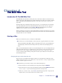
Introduction To The MAX Layout Generator .............................................................................................109
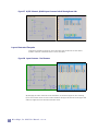
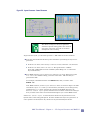
Layout Generator Examples ............................................................................................................................ 110
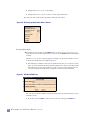
Edit Per-Cell Options .......................................................................................................................................... 112
Edit Stdcell Options ............................................................................................................................................. 113
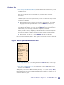
Edit Layers to Generate .................................................................................................................................... 115
Cross-probing .......................................................................................................................................................... 116
Cross-probing without the Layout Generator .......................................................................................... 118
Search Paths in MAX ......................................................................................................................................... 118
Chapter
6
MAX Technology
Targeting ..........................................................................................................121
Introduction To MAX Technology Files .......................................................................................................121
make_tech .................................................................................................................................................................121
Reading in GDSII Files .........................................................................................................................................123
gds_input ................................................................................................................................................................123
Layers - names and groups .............................................................................................................................124
Environment ..........................................................................................................................................................125
More on “gds_input” ............................................................................................................................................125
Converting a Dracula DRC File ........................................................................................................................126
drac_convert ..........................................................................................................................................................126
Technology Source Files ....................................................................................................................................126
Additional Statements ........................................................................................................................................132
Advanced Topics .................................................................................................................................................136
Other Commands ................................................................................................................................................136
MAX interactive DRC Limitations ...................................................................................................................138
Basic Technology Source File Example .....................................................................................................138
MAX User Manual -- Table of Contents
iii
Table of Contents
Appendix
A..................................................................................................................................................141
MAX Hotkeys
Appendix
B
MAX Text Commands
...........................................................................................................................143
Text Commands ......................................................................................................................................................143
Appendix
TCL/TK and C
The MAX API ................................................................................................................145
Writing Tcl/Tk Scripts ..........................................................................................................................................145
Useful Tcl Commands (MMI Extensions) ....................................................................................................145
Gcells Tcl Programs .............................................................................................................................................145
Example Gcell .......................................................................................................................................................146
Adding Commands to the Local Menu ........................................................................................................148
iv
Micro Magic, Inc. MAX User Manual -- v5.1.12
Preface
About This Document
This chapter provides an overview of the Micro Magic, Inc. MAX and MAX-LS Layout
Editor User Manual:
Objectives on this page.
Getting set up on page vii.
Objectives
This manual is a detailed guide to the Micro Magic, Inc. MAX, and MAX-LS Layout Editor.
Once you are familiar with the tool, this manual will act as a quick reference and how-to
guide. The best way to get started with MAX or MAX-LS is to run the MAX Tutorial.
Audience - MAX
This document is designed for layout designers and architects. It assumes that you have a
strong foundation in IC design and development, and layout design. This document also
assumes that you are familiar with the following programming languages and operating
systems:Tcl/Tk, and UNIX or Linux.
Organization
This manual is divided into several chapters. Each chapter deals with a different aspect of
the Micro Magic MAX/MAX-LS Layout Editor.
This manual contains the following chapters:
Preface, “About This Manual” (this chapter), provides a brief description of the content
and organization of this manual.
Chapter 1, “MAX Manual Overview”, introduces the basics of the MAX and MAX-LS
Layout Editors.
Chapter 2, “The MAX Layout Editor”, explains each section of the MAX window as well
as covering the basics of how to create layout with MAX.
Chapter 3, “MAX Commands”, goes through each menu in MAX and describes each
command.
Chapter 4, “The MAX Wire Tool”, covers how to draw wires in MAX.
Chapter 5, “The Layout Generator and MAX-LS”, goes through how to use the layout
generator, which is part of the MAX-LS Layout System, to generate schematic-driven
layout.
Chapter 6, “MAX Technology Targeting”, covers indetail how to create MAX technology
files.
Appendix A, “MAX Hotkeys”, references the hotkeys available in each mode in MAX.
MAX User Manual
-- Preface: About This Document
v
Appendix B, “MAX Text Commands”, points you to the documentation on the text
commands available in MAX.
Appendix C, “Tcl/Tk and the MAX API”, covers the basics of the MAX API, including an
example of a gcell program.
Chapter Organization
Each chapter contains descriptions of the commands and methodology necessary to create
layout using MAX, with step-by-step, illustrative examples describing the usage of
commands and procedures for generating schematics.
Documentation Conventions
General Conventions
This guide uses the following text conventions:
Statements, commands, command output, filenames, directory names, and
configurations are shown in a boldface, fixed-width font. The following example shows
a full path name:
~/mmi_private/max/.maxrc
In examples, text that you type literally is shown in bold. In the following example, you
type the word max:
To launch max, type max
Menus, menu options, and pop-up menus are generally shown in a boldface, sans serif
font. For example:
Select Save As from the File Menu.
Conventions for Software Commands and Statements
When describing the Micro Magic, Inc. software, this guide uses the following type and
presentation conventions:
Statement or command names that you type literally are shown nonitalicized. In the
following example, the statement name is set MC(default_generator):
set MC(default_generator) sram
Variables for which you substitute appropriate values, are shown in itallics. Optional
commands within a string of code are often enclosed within square brackets ([ ]).
Variables are enclosed within angle brackets (<>). When you type the setMACRO
statement, you substitute a value for name, row1 and row2. CELL is an optional
command.
set MACRO(<name>) {[CELL] <row1> <row2> ...}
vi
Micro Magic, Inc. MAX User Manual -- v5.1.12
Conventions for Mousing
Throughout this document, we assume you are using a 3-button mouse. When we refer to
using the mouse, the following settings apply:
Mouse-Button-1, or Button-1, refers to the left-most button (index finger) when you are
using a right-handed mouse.
Mouse-Button-2, or Button-2, refers to the middle, or center button (middle finger).
Mouse-Button-3, or Button-3, refers to the right-most button (ring finger) when using a
right-handed mouse.
Reverse these settings if you are using a left-handed mouse, using your mouse control
program, so that you click Button-1 with your index finger, Button-2 with your middle
finger, and Button-3 with your ring finger.
“Click” means to depress the designated mouse button once.
“Double-click” means to depress the designated mouse button twice, quickly.
“Drag” means to depress and hold down the designated mouse button while moving the
mouse.
Documentation Feedback
We are always interested in hearing from our users. Please let us know what you like and
do not like about the Micro Magic, Inc. documentation, and let us know of any suggestions
you have for improving the documentation. If you find any mistakes or out of date
information, please send email to [email protected].
Support
For product problems or technical support issues, contact Micro Magic, Inc. at
[email protected].
Getting set up
MAX runs independently from any of the Micro Magic, Inc. tools suite.
First, ensure that the Micro Magic, Inc. software has been installed, and that you have a
valid MAX license.
This document copyright © Micro Magic, Inc.
MAX User Manual
-- Preface: About This Document
vii
viii
Micro Magic, Inc. MAX User Manual -- v5.1.12
Chapter
Overview 1
Introduction
This manual is for both MAX and MAX-LS. MAX is a full-custom IC layout tool for physical
layout of leaf cells, large blocks and complete SoC products. MAX also has a complete
programming interface via Tcl/Tk and a well-documented API. Whether you need fullcustom layout, cell-assembly, chip-assembly or the ability to write your own generators,
MAX is the tool to choose for your physical design needs.
MAX is equally at home in all aspects of physical design, from creating cells for a library, to
interacting with place-and-route at the block-level, to assembling an entire chip. While
MAX is powerful enough to handle the largest of chips, it's easy to learn and easy to use.
MAX-LS is a layout system that incorporates our best tools for IC physical layout design of
leaf cells, large blocks and complete SoC products. MAX-LS features true schematic driven
layout design, including interactive cell generation based on LVS and DRC-correct
generators, and cross-probing between schematic and layout.
MAX-LS schematic driven layout offers the ability to generate layout that is DRC and LVS
correct with devices automatically sized. Based on your schematic, MAX-LS can generate
every transistor and show flylines as to how they should be connected. This gives the layout
designer complete control, yet assures rapid physical design development.
MAX Features
Interactive viewing and editing of hierarchical layout
Continuous DRC feedback during layout
Hierarchical and incremental DRC
Interactive connectivity tracing
Interactive wiring tool
Generators for layout structures such as nfets or pfets.
Interfaces to other tools, including schematic capture (for example SUE), and batch
DRC and LVS (for example Dracula or Calibre).
Smart palette for easy control and feedback on layers.
Reads/writes GDSII.
Full customization and extension via Tcl/Tk scripting language and API.
Technology independence via technology description files.
Optimized for large databases.
Chapter 1 -- Overview
1
MAX-LS Features
All the features of the MAX layout editor listed above.
SUE schematic viewing and editing (Refer to the SUE User Manual for details on how
to use SUE).
Layout generator for automatically generating layout from a schematic.
Cross-probing between layout and schematic.
MAX Basics
MAX uses the idea of paint as well as objects. Paint defines the mask geometries: where
each mask is opaque and where it is clear. MAX is different from many layout editors in
that mask geometries are not maintained as a list of fixed rectangles, wires, etc. as entered
by the user, but rather as paint regions which have no memory of the constituent rectangles
from which they were originally constructed. Additionally, MAX layers do not always
correspond exactly to Mask layers. The See Mask command allows you to preview actual
masks.
In addition MAX can also do object-based layout using Gcells (generator cells), polygons,
circles and wirepaths. Gcells can be flattened down to paint for complete editing control.
MAX organizes layout into cells. Each cell, saved in an ASCII file of the same name,
contains paint, Gcells, polygons, labels and instances of other cells.
Labels associate text with points or rectangles in the design on a given layer. Labels and
text come in flavors and are used to define cell input and output ports, and comments.
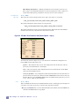
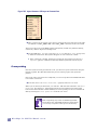
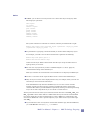
Instances of cells are placed by clicking on the cell names in the lists along the right side of
the MAX window (see Figure 1 ) while holding down the Shift key.
Clicking on a cell entry without the Shift key changes the view to that cell. If the
cell you want is not in the cell lists, you will first have to load it into memory (See
Open on page 34). An entire directory of cells can be loaded into MAX by selecting
Autoload directory at the top of a cell list.
Instances can be shown in two ways: abstractly (only name, ports and bounding
box shown), or with internals displayed (refer to Internals, View Area (see
page 84)).
When a cell is loaded, only the abstracts are shown for the instances.
The function of the mouse buttons and hotkeys in MAX vary with the mode MAX is in. For
a summary of the current function of mouse buttons and hot keys, hit the Space bar at any
time. Also check the message area to the right of the menu bar for information on the
current mode. (See page 151 for a summary of the hotkeys.)
The hotkeys for panning and zooming around, and for controlling the grid, work in all
modes, (even when in the middle of dragging something around with a mouse button
depressed).
2
Micro Magic, Inc. MAX User Manual -- v5.1.12
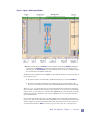
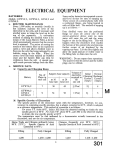
Figure 1: Figure 1: MAX Layout Window
MAX's main mode, mouse Button-1 (left) is used to select things, Button-2 (middle) is
used to pan, and Button-3 is used to move selected around. If you are using a scrollwheel mouse, the scroll-wheel is used for zooming in/out as well as scrolling throught
the cell list boxes and window slider bars.
In addition to the traditional cursor, MAX has a box (with the default color of brown) that is
used to specify areas.
To position the box, in main mode, type b and then drag out a box with Button-1.
To paint a rectangle (specify the layer), point to the layer to paint (either in the
layout or in the palette on the left side of the MAX Window) and type the hotkey p.
The Wire Tool is a much easier way to create interconnections as opposed to specifying
each rectangle. In addition, Gcells shown in the top cell list are an easy way to generate fets
and vias. The Layout Generator which is part of MAX-LS gives you the ability to quickly
generate layout from a schematic. Also as part of MAX-LS, you can cross-probe between
layout and schematic.
As you create and modify the layout, you will probably notice white dots appearing from
time to time. This is the continuous background DRC's way of complaining. To find out the
specific design rule violations behind the white dots, position the box over the region you
are interested in and type Shift-y, or choose Explain DRC under Box (see page 104)
MAX User Manual - Chapter 1 -- Overview
3
A popular feature in MAX is the ability to quickly trace connectivity. To select an entire net,
just position the cursor over a geometry and type the hotkey s (See “Select Net” on
page 92.). The entire net is highlighted and the labels found on the net are listed in the
Message Area.
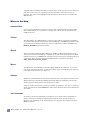
Where to Get Help
Demonstration
If you are new to MAX, the best place to start is with a demonstration from the friendly
folks of Micro Magic, Inc. If you have not already seen a demo, pick up the phone and
schedule one now!
Tutorial
The Micro Magic, Inc. MAX Tutorial is a step by step, hands on, introduction to MAX. It
can be started at any time from the Help menu in MAX. It is in HTML form, and will come
up in Netscape (or another browser of your choice). The browser used is specified by the
DEFAULT_BROWSER environment variable.
Manual
You are currently reading the Micro Magic, Inc. MAX User Manual. The manual is the
authoritative reference for MAX. It is available at any time from the Help menu in MAX.
Like the tutorial, it is in HTML form, and will come up in Netscape (or another browser of
your choice). There are also postscript and PDF versions available for printing in
$MMI_TOOLS/doc/max/max_manual.
Menus
For information on commands, browse through the MAX menus. Note that, as you move
over menu items with the cursor, on-line descriptions appear in the Message Area directly
to the right of the menu bar (see Figure 1 ).
Hotkeys
Hotkeys are provided for most menu items, and are shown at the right of the menu entries.
These hotkeys are available from MAX's main mode. When in submodes, such as when
drawing wires or editing labels, other hotkeys are in effect.
A list of currently active hotkeys is always available by clicking on Hot Keys in the Help
menu, (alternately just hit the Space-bar). The current functions of the mouse buttons are
also listed.
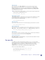
Text Commands
An extensive set of text commands is available for use in scripts. These commands are
mainly of interest to developers implementing new menu items, startup scripts, etc.
However, text commands can be invoked directly, by typing into the window from which
MAX was started.
4
Micro Magic, Inc. MAX User Manual -- v5.1.12
For documentation on text commands, click on Text Commands (see page 107) in
the Help menu or type the hotkey ?. Click on the one line description of a command
for more detailed information.
You can search for commands whose documentation contains selected keywords, by
typing them into the Search field at the bottom of the text commands window.
For example, to search for commands related to saving files, you can enter file save
into the Search field.
Text commands are built on top of Tcl/Tk. All Tcl and Tk commands are available
providing a complete scripting language and toolkit for GUI extensions. This version uses
Tcl/Tk 8.4.9 with Micro Magic enhancements. Complete information on Tcl/Tk is
available from the official Tcl/Tk website at http://scriptics.com. We also
recommend the book Tcl and the Tk Toolkit, authored by John Ousterhout, and published
by Addison-Weseley.
Micro Magic Documentation Guide
MAX is closely tied to a number of other programs in the Micro Magic Inc. design tools
suite. For example, MAX can be used together with SUE Design Manager to
simultaneously view a design at schematic and physical levels, with cross-probing between
the two. Several utility programs, such as Ext2sim, post-process MAX output for use with
other programs. For information on these other programs, check out the Micro Magic, Inc.
Documentation Guide. The guide summarizes all the tools in the Micro Magic design suite
and provides pointers to complete documentation.
The Micro Magic, Inc. Documentation Guide can be accessed from inside MAX by clicking
on MMI Documentation Guide in the Help menu. Alternately, the program mmidoc brings
up the guide in your favorite browser. Simply type mmidoc in a shell window and the Micro
Magic, Inc. documentation will be brought up in your browser.
The Friendly Folks of Micro Magic, Inc.
If the above sources are insufficient, do not hesitate to contact the Micro Magic group. You
can send email to us at: [email protected]
MAX User Manual - Chapter 1 -- Overview
5
6
Micro Magic, Inc. MAX User Manual -- v5.1.12
Chapter
2Editor
MAX Layout
Running MAX
This chapter covers information on how to run the MAX layout editor.
To start MAX, simply use the max command as defined below. Each release of MAX comes
with a set of generic technology files, so you can get started entering layout using one of
these technologies. The gds_input (page 125) command gives the user the ability to easily
read in GDSII files without an existing technology file.
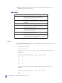
MAX Command Line Description
Synopsis
Description
max [-switch value] [[cell_name1, cell_name2,...] | [gds_file]]
This launches the MAX Layout Editor. The -tech option is used to specify which
technology will be used. Numerous cells can be specified to load up at runtime, or they can
be opened after MAX is started. If a cell name is specified, MAX starts with the technology
specified in that MAX file. Below is a list of the switches for the max command.
Chapter 2 -- MAX Layout Editor
7
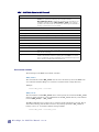
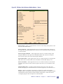
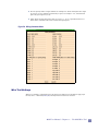
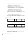
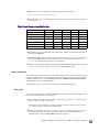
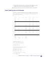
Table 1: List Of Switch Options For MAX Command
Option
Description
-tech tech_name
Specify the technology which will be used. The default technology is used if tech is not specified. It is defined by the environment variable
MAX_DEFAULT_TECH. If a MAX cell is specified on the command line, the
technology of that cell overrides MAX_DEFAULT_TECH. If the technology
specified on the command line does not match the technology of the MAX file, a
warning is printed and the cell is not loaded.
-h | -help
Prints out syntax of the max command
-v | -version
Print the version of MAX and exit.
-geometry XxY+T+Z
Start MAX with the given X and Y size at the given T and Z coordinates.
-colormap new
Start MAX with a private colormap
-iconify 1
Start up MAX iconified
-batch 1
Run MAX in “batch” mode, which means no pop-ups or confirmations required.
-new <cell>
Bring up MAX with a new cell.
-command <tcl_cmd>
After the .maxrc files have been read in, execute the Tcl command at startup.
-set <var>=<value>
Set a global variable at startup. Variables can also be set in a .maxrc file.
cell_name1,...
Specify the cells to open while loading MAX. All cells must have been laid out
with the same technology.
gds_file
If a GDSII file is specified, MAX will first translate the GDSII file to MAX
format. If the extension of the file is anything other than .max, it is assumed
that it is a GDSII file. Specifying a GDSII file on the command line requires that
there is already a technology file created for this cell.
Environment Variables
The following are the MAX environment variables.
MMI_TOOLS
The environment variable MMI_TOOLS must be set to the directory where the MMI tools
were installed. All Micro Magic, Inc. software is installed under a single directory.
Example:
setenv MMI_TOOLS /tools/mmi
MMI_LOCAL
The environment variable MMI_LOCAL can be used to specify the location of the mmi_local
directory. If this variable is not set, MAX looks for the mmi_local directory in the default
location $MMI_TOOLS/../mmi_local.
The mmi_local directory is where site or company specific information is stored. This is
where the technology files should be located. Any settings specified in mmi_local for
hotkeys, colors, etc. override the default settings in MAX.
setenv MMI_LOCAL /tools/mmi_local
8
Micro Magic, Inc. MAX User Manual -- v5.1.12
MMI_PRIVATE
The environment variable MMI_PRIVATE can be used to specify the location of the
mmi_private directory. If this variable is not set, MAX looks for the mmi_private
directory in the default location directly under you home directory at ~/mmi_private.
The mmi_private directory is where user specific information is stored. You may have
your own hotkey and color settings.
Any settings specified in mmi_private override the default settings for MAX and the
settings defined in the mmi_local directory.
setenv MMI_PRIVATE ~/mmi_private
MAX_DEFAULT_TECH
If MAX_DEFAULT_TECH is set, MAX defaults to this technology. The -tech option overrides
the environment variable. the default technology for MAX is set to mmi25 which is a
generic technology file provided with MAX.
setenv MAX_DEFAULT_TECH mmi25
MMI_BROWSER
This determines which web browser is used when bringing up documentation or tutorials.
setenv DEFAULT_BROWSER netscape
MMI_LICENSE_FILE
This specifies the location of the MMI license file. If not set, MAX looks for the license file in
$MMI_TOOLS/../mmi_local/mmi_license.lic or in $MMI_LOCAL/mmi_license.lic.
setenv MMI_LICENSE_FILE $MMI_LOCAL/mmi_license.lic
MMI_EDITOR
This environment variable is used mainly in SUE. If the tool needs to bring something up
in a text editor, it will use the editor specified by MMI_EDITOR.
MAX_PROBE_DISPLAY
MAX_PROBE_DISPLAY is used with MAX-LS. It specifies which display MAX will attempt
to bring up SUE in for crossprobing.
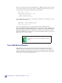
The .maxrc File
The .maxrc file contains commands which are added to Local or Tool menus, define
variables, and execute text commands. In addition, Tcl programs can be defined or sourced
in the .maxrc file. Below is an example of a .maxrc file which sets the variable
ZOOM_BUTTONS (See “Zoom Buttons” on page 19) then sources a Tcl script, adds a
command to the Local menu and turns off the interactive DRC on startup.
The file can be named .maxrc or max.rc.
set ZOOM_BUTTONS "green yellow purple orange blue"
source $MMI_LOCAL/max/tree.tcl
menu_local_cmd "Print hierarchy tree" print_tree
pal_special_off drc
MAX User Manual - Chapter 2 -- MAX Layout Editor
9
There are a number of locations where MAX looks for a .maxrc file. Below are the locations
in the order in which they are sourced. The last .maxrc file found (usually the one in the
current directory) will override settings from the previous files.
$MMI_TOOLS/max/.maxrc
$MMI_TOOLS/../mmi_local/max/.maxrc
~/mmi_private/max/.maxrc
~/.maxrc (home directory)
./.maxrc (current directory)
The MAX subdirectory can contain a version number, allowing you to run different versions
of the software. For example:
$MMI_TOOLS/../mmi_local/max5.0/.maxrc
$MMI_TOOLS/../mmi_local/max/.maxrc
~/mmi_private/max/.maxrc
If you are running MAX version 5.0 or later, MAX will get the .maxrc files from
mmi_local/max5.0 and mmi_private/max. If you are running a version of MAX earlier
than 5.0 (for example, MAX 3.2), MAX will get the .maxrc files from mmi_local/max and
mmi_private/max. MAX looks for a max directory with the latest version not exceeding
the version of MAX which is being run. For versions before MAX 3.0, MAX only looks at the
max directories, no version numbers
Remember, you can name your file max.rc as well as
.maxrc.
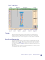
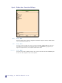
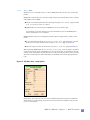
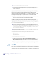
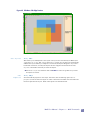
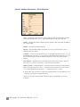
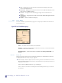
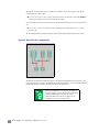
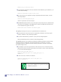
Tour of MAX Window Elements
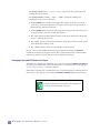
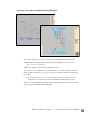
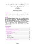
When MAX starts up, it creates a new main window. The main window has a large grey
(default color) area for displaying layout in the center, surrounded by various other
elements. (See Figure 2). The purpose and use of these other elements is described below.
Most of the elements are optional and can be removed (see “Display Options” on page 42) to
increase the area available for displaying layout.
10
Micro Magic, Inc. MAX User Manual -- v5.1.12
Figure 2: The MAX Window
Title Bar
The window title bar (displayed at the top of the window by most window managers)
identifies the window as a MAX window and gives the name of the cell loaded into the
window. If an edit-in-place is currently in progress, the cell being edited is also identified.
Menu Bar and Message Area
At the top of the window, normally just below the title bar, are the Menu Bar (on the left)
and Message Area (on the right). The menus are scanned, and menu items are invoked, by
clicking the menu with Button-1 and then clicking on the menu item. You can also select
menu options by holding down Button-1, dragging down to highlight the desired item, and
then releasing.
You can tear off a menu, and place it in a permanent window of its own. To do so, just click
on the dashed "tear line" at the top of the menu.
MAX User Manual - Chapter 2 -- MAX Layout Editor
11
Message Area
Note that when the cursor is over a menu item, a short description of it appears in the
Message Area to the right of the menus. When the cursor is not over a menu item, the
Message Area normally displays information on the current mode and function of the
mouse buttons. Occasionally the Message Area is used to display other useful information,
such as the highlighted DRC error when stepping through DRC errors.
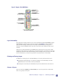
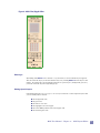
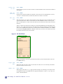
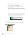
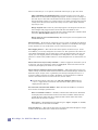
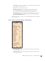
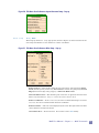
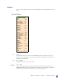
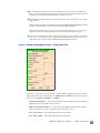
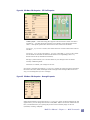
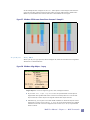
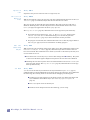
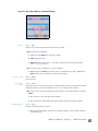
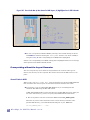
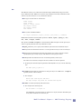
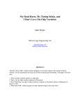
Palette
The MAX palette, located along the left border of the main MAX window, displays the
available layers, visibility, selection status, and cursed layers (layers under the cursor).
Furthermore, layer visibility and/or selectability is changed on a layer by layer basis, by
groups of layers or by all layers. Also, the selectability of subcells and Gcells is changed by
clicking on the box labeled -cells-. Refer to Figure 3 for details.
Active Layer
The top button in the palette specifies the Active Layer. The default setting is auto, used
for the Wiring Tool on page 27. The Active Layer controls what layer polygons and circles are
drawn in. It also controls the layer wires start in.
Layers Under Cursor
From left to right, for each layer, the palette contains a small rectangle that turns red when
the cursor is over that layer in the Layout Window — known as a cursed layer. The layer
does not need to be visible to be cursed. However, layers in unexpanded subcells (cells for
which internals are not visible) are not cursed.
Layer Visibility
The next rectangle displays the visibility of the layer. If this layer is visible, the rectangle
will contain the fill pattern and color of the layer. Toggle layer visibility on or off by clicking
on the rectangle with Button-1.
To toggle on or off visibility of groups of layers, click with Button-1 on the group
name (for example: -active-). (Refer to Figure 3, below.)
12
Micro Magic, Inc. MAX User Manual -- v5.1.12
Figure 3: Regions of the MAX Palette
Layer Selectability
The right-most rectangle shows the layer name and indicates layer selectability and the
selected layer. All layers start out being selectable. Click Button-1 on this rectangle to
"grey out" the rectangle, and the layer is no longer selectable. When you drag out a
selection in the main MAX window, only those layers both visible AND selectable will be
selected.
If the layer is selected anywhere in the MAX layout (it does not have to be in the visible
window), the text will turn red. Otherwise it is black. Note that it is possible to be selected
(displaying red text) but with the selectability off. For example, when you select a wire and
trace its connectivity, you may select geometries on layers that are not selectable.
Painting and Erasing Layers
In addition to selecting layers, in the Main Mode you can also paint and erase layers.
Clicking the paint hotkey p over either the visibility or the selectability area will
paint that layer into the box in the Layout Window.
Clicking the erase hotkey o will erase that layer from inside the box in the edit cell.
Groups of Layers
You can control the visibility and selectability on a layer-by-layer basis, as described
above, or by groups or all layers.
MAX User Manual - Chapter 2 -- MAX Layout Editor
13
The group buttons (metal, active, other) control all of the layers below them
until the next group button.
The group buttons (-cells-, -all-, -text-) control the visibility and
selectability of cells, text, or all layers.
Clicking Button-1 on a group button toggles the visibility of all the layers in the
group. If any of the layer visibilities are off, then all the layers will be turned on.
Otherwise they will all be turned off.
Clicking Button-3 on the group button toggles the selectability of each of the layers
in the group in the same way as with the visibility.
The -all- button has the same functionality as the group button but controls all
layers — a kind of super-group.
The -text- button has the same functionality as the layer buttons but controls the
selectabililty and visibility of text.
The -cells- button controls the selectabililty of cells instances
Groups of layers can be hidden and restored in the palette by clicking with Button-2
(middle mouse button) on the group button. This is useful if the palette is cluttered with
infrequently used layers. Note that all layers are displayed on startup.
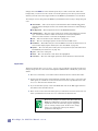
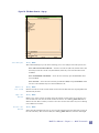
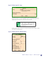
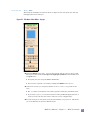
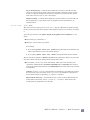
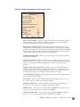
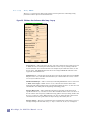
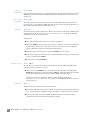
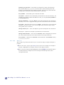
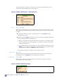
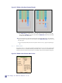
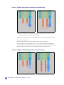
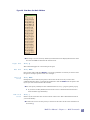
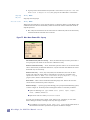
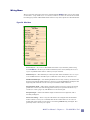
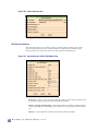
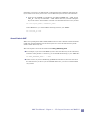
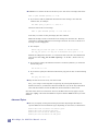
Changing Color and Fill Patterns of Layers
To edit the color, fill pattern, and outline style of any layer, click with Button-2 or Button-3
over that layer’s palette entry (either the layer name or color/fill square). This brings up a
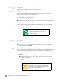
color/stipple editor, as shown in Figure 4.
If the editor is already open, just change the layer to the desired layer by selecting the layer
in the Edit layer popup, or by clicking with Button-2 or Button-3 on the desired layer.
Note that if the editor is obscured by other windows or
iconified, this will deiconify or raise it.
14
Micro Magic, Inc. MAX User Manual -- v5.1.12
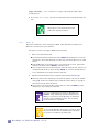
Figure 4: MAX Color/Stipple Editor
Edit Layer
By holding down Button-1 over the Edit Layer button, a list of available layers appears.
You can select the layer you wish to edit this way or by clicking Button-3 on the layer in the
palette. To change the color and stipple patterns of special layers (background, grid, etc.),
you must select the layer through this pop-up.
Editing Special Layers
Contained within the color/stipple editor layer selection is a list of special layers that
you can modify. These include:
the background color,
the grid color,
the label or text color,
the highlight color and stipple,
the online DRC feedback color and stipple, and
the bounding box color.
MAX User Manual - Chapter 2 -- MAX Layout Editor
15
Simply click with Button-1 on the desired special layer to edit it. Note that, other than
background, you will not see the current color of the special layer in the top color window.
Instead you must look at the stipple window or the MAX Layout Window to see the effect.
For example, turn on the grid in the MAX Layout Window before trying to change the grid
color.
annotation — The color of objects created with the API commands lay_line
and lay_rect. Examples are the ruler and the edit lines/vertices when editing a
polygon.
background — The background color for the MAX Edit Window.
cell bbox/text — The color of the outline of an instance (bounding box), instance
type, and instance name for which no internals are viewed (unexpanded
instances). If the instance is selected, the highlight color is used.
box — The color of the box (See “The Box” on page 25)
drc — The color and stipple pattern for the interactive DRC errors.
feedback — The feedback layer is used for DRC errors from an external tool. It is
also used for displaying the mask layers. (See “See Mask” on page 80)
flyline — The color of flylines used by the layout generator (See “Introduction To
The MAX Layout Generator” on page 117).
grid — The color of the grid.
label — The color of labels or text when not highlighted.
selection — The color and stipple pattern for items which have been selected.
Layer Color
From top to bottom, the color/stipple editor lets you edit the color of the current layer.
Simply change the hue, saturation, and brightness (HSB) sliders or RGB (red, green, blue)
sliders.
The hue is essentially a color wheel. Choose the desired color with the hue slider.
Next change the saturation and brightness if needed. There is also a color select list
which gives you a fixed set of colors to start from. To select a predefined color, click
on Colors and select the desired color.
If you would rather specify colors with RGB, then click on the RGB toggle and move
the sliders to the desired locations.
There is also a color select list which gives you a fixed set of colors to start from. To
select a predefined color, click on Colors and select the desired color.
Because any changes you make in the editor affect the
MAX Layout Window in real time and cause MAX to
repaint the screen, the editor may appear sluggish if
you are viewing a large layout. If this occurs, simply
zoom in on a small part of the layout and the
performance will improve.
16
Micro Magic, Inc. MAX User Manual -- v5.1.12
Layer Fill and Outline
Next in the color/stipple editor, you can select whether the fill for a layer is solid or
stippled.
Solid layers appear solid in the layout but are also transparent to other layers. Solid
layers are the easiest to see and it is suggested that all common layers be made solid,
such as diffusion, poly, and metal layers (but not vias). Solid layers do not have stipple
patterns nor outlines.
Stippled layers are suggested for vias and less common layers like n-well and pplus.
Stipples can be outlined.
You can edit the stipple pattern of a stipple by clicking with Button-1 on the squares
of the stipple to toggle them on or off.
You can also click with Button-1 on any of the provided stipple patterns to set the
current stipple.
Selecting the outline button will draw a single pixel outline around any region
with that stipple pattern.
Via Styles
If you are changing the color of vias, you can also change the via style. Often times
vias don't use stipple patterns, but have a simple "x" or "+" in it. MAX provides you
with four different via styles.
Palette File
The bottom of the color/stipple editor provides a file find... bar and the buttons
Close, Revert..., Load and Save.
find... allows you to specify a file name to load or save which contains the layer color and
stipple patterns.
The default location for this file is:
~/mmi_private/max/tech/<tech name>/<tech name>override.
If you save your color and stipple information in this file, it will be automatically
loaded when you start MAX with the same technology.
Close closes the color/stipple editor without saving edits.
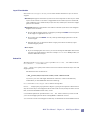
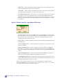
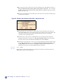
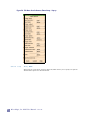
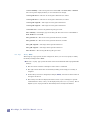
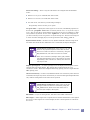
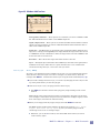
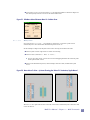
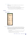
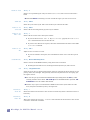
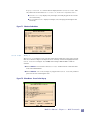
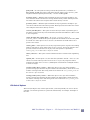
Revert... brings up the pop-up shown in Figure 5, giving several options to discard all or
only the current layer colors/stipples from the last saved version (usually the same version
that you started the MAX session with)., and to
Load loads the palette file specified in the find... bar. This is useful if you want to load
your color and stipple patterns while running MAX in a different account.
Save saves the current colors/stipples so that they are the default for future MAX sessions.
MAX User Manual - Chapter 2 -- MAX Layout Editor
17
Figure 5: Revert Options
Saving the Palette and the .override file
The palette layers, groups, and colors/stipples are saved in a file called <tech>.palette
where tech is the name of the technology (for example, mmi25). This file is created when
the technology files are made using make_tech (see Chapter 6, "MAX Technology
Targeting").
When you click Save, MAX will attempt to save a local copy of the palette color and
stipple patterns into the file specified in the find... bar. By default the file is stored
in::
~/mmi_private/max/tech/<tech>/<tech>.override
If you do not have this directory, MAX will create the appropriate directory in UNIX. If
you want these palette options to affect all other users, you can UNIX move it to:
${MMI_TOOLS}/../mmi_local/max/tech/<tech>/<tech>.override
The <tech>.override file only changes the color and stipple patterns of layers. It does
not change the grouping or layer order in the palette. This information is specified in
the <tech>.palette file and is only loaded when MAX is invoked.
The order of the layers in the <tech>.palette file determines the order of layers in
the palette in MAX. You also edit the palette file to modify the placement and names of
groups.
The .override file is an ASCII file that you can edit directly. Colors are specified
as RGB triplets, and stipples as 1’s and 0’s.
If you want to rearrange layer orders or add/subtract/modify groups, you must
presently do it in the palette file. You can then re-launch MAX to view the results.
The SAMPLE_STIPPLES variable allows you to change the default stipples showing
in the color palette. Refer to “Text Commands” on page 107 for more information.
If you do edit the .palette file or the .override file
directly, be careful to preserve the syntax or else MAX
won’t be able to read it.
18
Micro Magic, Inc. MAX User Manual -- v5.1.12
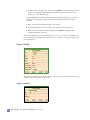
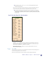
Cell Lists
Along the right side of the window are lists containing names of cells currently loaded into
memory. Each list pertains to cells in a particular UNIX directory.
The top cell list is generally the Gcells (page 25) provided with MAX. The number of
lists, and the directories they display, can be controlled by clicking on the directory
names at the top of the lists.
To customize the list boxes that display loaded MAX cells, use the API command
list_box_configure. (Refer to Appendix C, “TCL/TK and The MAX API” for
information about API commands.)
Clicking on a cell name (except for Gcells) with Shift-Button-1 causes that cell to be
displayed in the Layout Window.
Button-1 puts an instance of that cell in the Layout Window. You can position the
instance by moving the mouse using Button-1 or Button-3 to place the instance.
Clicking with Button-1 on a Gcell brings up the Gcell Edit Properties (page 67)
form.
An “M” to the left of a cell indicates that it has been modified since last saved to
disk.
An “R” indicates that the disk file is read only.
An “S” indicates that the cell has been saved to disk.
A “B” indicates that the cell resides only in the memory buffer and has never been
saved to disk.
A “G” indicates that the cell is a gcell.
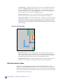
The Navigator Window
If you have zoomed in on a portion of a cell, the Navigator Window in the lower right corner
shows you a rectangle representing the entire cell.
A red box represents the zoomed in area.
The white box in the Navigator Window shows the current location of The Box
(page 25).
Clicking once with Button-2 or Button-3 in the Navigator Window moves you to that
region in the edit window.
Drag out an area in the Navigator Window with Button-1 to zoom to a specified
region of the cell in the edit window.
Zoom Buttons
On the right side of the Navigator Window are three zoom buttons. The top zoom button
(green by default) lets you go backward and forward in the zoom stack.
MAX User Manual - Chapter 2 -- MAX Layout Editor
19
Clicking Button-1 on this top button lets you step backwards one view at a time
through your previous views.
Clicking Button-3 on this top zoom button lets you step forwards one view at a time.
This only works if you have already gone backward to previous views.
The other zoom buttons allow you to save a specific view (for example, if you have
zoomed into a specific area of the layout) and return to that view later.
To set the zoom buttons:
First zoom in on a desired area of the layout.
Then click on a zoom button (other than the top button) with Button-2 or Button-3.
Notice that you now see a box — of the same color as that button in the Navigator
Window — indicating the location of this view.
To get back to a view, click on the desired zoom button with Button-1.
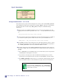
To customize the Navigator Window, you can set ZOOM_BUTTONS in the .maxrc file
as shown below.
In this example, we will add four additional zoom buttons, and change the top zoom
button to yellow, with the command:
set ZOOM_BUTTONS "yellow green purple orange blue"
This command can be typed into the Command Window to change the zoom buttons on
the fly or can be added to a .maxrc file. (See “Creating and Editing Layout with MAX”
on page 22).
The Bottom Bar
The bar at the bottom of the window holds four elements:
DRC Status Area
Zoom Bar
Selected Area
Cursor Coordinates
Box Area Display
DRC Status Area
The DRC Status Area is at the left end of the bottom bar. The messages it displays and
their meaning are described below. When active, the background DRC runs continuously
and DRC errors are displayed as white dotted areas.
For an explanation of a DRC error, drag a box around the error with Button-1 and
select Explain DRC under Box (page 104) from the Misc menu.
20
Micro Magic, Inc. MAX User Manual -- v5.1.12
If only one DRC error occurs under the box, that single error is displayed in the
Message Area.
Otherwise, the DRC errors are listed in the Command Window (the shell window
from which you started MAX).
The DRC Find Next Error (page 103) command, also in the Misc menu, can be
used to step through all current DRC errors. The text explanation of the DRC
error is displayed in the Message Area.
drc off
The DRC processing is turned off. When a large GDSII file is first read in, MAX runs
DRC on the entire layout in the background if DRC is turned on. “drc off” means
that the interactive DRC is not running.
The visibility of DRC errors can be toggled by clicking on the drc button to the left of
the DRC Status Area. This also toggles the DRC on/off
In other words, making DRC errors visible automatically turns the DRC on, and
making errors invisible turns it off.
drc busy
The background DRC is on and running, and has unfinished business.
drc clean
The DRC is up-to-date and there are no MAX DRC errors.
drc n errors
The DRC is up-to-date and there are n DRC errors.
drc >10 errors
The DRC is up-to-date and there are more than 10 DRC errors.
Zoom Bar
The Zoom Bar is located in the middle of the bottom bar. It works like a scroll bar, except
that it zooms in or out, rather than panning over.
Selected Area
The Selected Area is located to the right of the Zoom Bar. This area indicates how many
things are selected. By default, if more than 100 things are selected, it displays ">100".
You can change this number with the variable SELECT_MAX_DISPLAY. By default,
everything is counted when displaying the number.
MAX User Manual - Chapter 2 -- MAX Layout Editor
21
To change this, you can use the variable SELECT_DISPLAY. For example, if you
want only cells or text counted in the Selected Area, type the following command in
the Command Window or add it to a .maxrc file.
set SELECT_DISPLAY "cells text"
If you click on this area with Button-1, the Selection Probe window appears,
showing details of what is selected.
Cursor Coordinates
To the right of the Selected Area is an area displaying the Cursor Coordinates. The
coordinates are for the cell which was opened.
If you do an Edit Cell or Object in Place (page 80), the coordinates displayed
will be for the original (top level) cell.
Clicking on the Cursor Coordinates area with Button-1 opens a pop-up form allowing
you to specify exact coordinates of where to move the cursor.
Box Area Display
The Box Area Display at the right end of the bottom bar gives the current box dimensions
as width (dx) x height (dy) in microns. Also displayed is the area of the box.
You can change what is displayed in the Box Area Display by clicking in Box Area
with Button-1.
You change what is viewed by editing "Display on status bar, box:". This pop-
up form also appears when you select Box Dimensions from the Misc menu.
The Box Area can be used to “measure” objects by selecting them. (When you select
something the box is automatically placed around it.)
The Box Area can also be used to measure the space between things, using the
hotkey m. The hotkey m is for the Measure (page 96) command in the Misc menu.
You really need to use the hotkey, since you need the cursor positioned at the space you
are measuring when issuing this command.
Scroll Bars
Scroll bars for the layout area allow you to pan vertically or horizontally through the
layout. There are also scroll bars for the cell lists.
Creating and Editing Layout with MAX
Command Window
The shell window MAX is started from is also of interest during the operation of MAX.
Informational messages are posted to this window.
22
Micro Magic, Inc. MAX User Manual -- v5.1.12
For example, the results of the Explain DRC under Box (page 104) command are
displayed in the command window.
In addition, text commands, or even entire Tcl scripts can be typed into the Command
Window (See “Text Commands” on page 107). Text commands are of use primarily to
developers, but are occasionally useful to end-users who wish to access (obscure)
features not available from the menus.
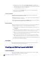
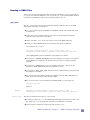
Reading In A GDSII File
In order to read in an existing GDSII file, you must first create a basic MAX technology file
which defines the layers in the GDSII input. If there is no existing technology file, use the
gds_input (page 131) command to create a basic technology file by looking at what layers
exist in the GDSII file.
This technology file will contain only the layer definitions with no DRC rules, no layer
connectivity, and no definitions for Gcells. It is useful for quickly viewing a GDSII file or as
a starting point for a new technology file.
The Import File (page 34) command (under the File menu) assumes that you have a
technology file.
Creating A MAX Technology File
MAX comes with generic technology files (mmi25 and mmi18) for a 0.25 µm and 0.18µm
process. These can be used as a starting point for creating new technologies. A technology
for MAX is defined in the technology source file. The make_tech (page 129) program is
then used to convert the technology source file into the technology files used by MAX.
If you have a Dracula DRC deck for the technology, the drac_convert (page 134) program
can be used to create a MAX technology source file.
Please refer to Chapter 6, "MAX Technology Targeting", for detailed information on
gds_input, MAX technology source files, make_tech and drac_convert.
Basic MAX Usage
This section of the manual gives a quick overview of the basic things you can do in MAX.
Refer to Chapter 3, "MAX Commands" for a complete description of all MAX commands. A
great source of information on the basics of using MAX is the Micro Magic, Inc. MAX
Tutorial.
Typing Ctrl-c aborts out of the current mode, undoing any changes and returning to
the Main Mode. As an example, in Wire Mode, Ctrl-c will abort the wire you are
working on and return you to the Main Mode.
Typing ESC ends the current mode and returns to the Main Mode. For example, if
you are working in Wire Mode, ESC ends the wire you are working on and returns
you to the Main Mode.
MAX User Manual - Chapter 2 -- Creating and Editing Layout with MAX
23
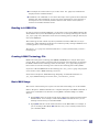
Moving Around the Layout
Zoom, Pan, Scroll Bars, Zoom Window
Once you have loaded a layout in MAX, there are many ways of moving around in the
layout.
Use the command Zoom to Area (page 82) (hotkey: z) to specify the region to zoom
in on. You type the hotkey z and then drag out the region to zoom to with Button-1.
Use the command Zoom to Fit Selected (page 82) (hotkey: Shift-v) to zoom in to
fit what is selected.
The Zoom Out (page 82) command (hotkey: shift-z) allows you to zoom out by a fixed
amount.
The Zoom In on Cursor command (hotkey: j) allows you to zoom in by a fixed
amount, centered on the cursor.
Use the scroll-wheel on the mouse to zoom in and out on the layout. The zoom area
will be centered around the point of the cursor.
Use the scroll bars on the bottom and right of the Layout Window to pan around the
layout.
In addition, you can use the The Navigator Window (page 19) to move around the
layout.
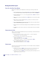
Viewing Internals of Cells
When a cell is first loaded into MAX, only the top level of hierarchy is visible. The internals
of instances are not visible.
To view all internals of all cells, use the Internals, View Area (page 84)
command (hotkey: i) to view the internals.
To view internals of only selected cells, first select the cells
(Select cell, hotkey: f)
(Select additional cell, hotkey: Shift-f),
and then use the Internals, View Cell command (hotkey: Shift-i).
You can hide internals of all cells (hotkey: h) or
hide internals of selected cells (hotkey: Shift-h).
Viewing Layers
The palette on the left of the layout area allows you to turn on/off the visibility of individual
layers or groups of layers.
Clicking once with mouse Button-1 (left mouse button) on an individual layer (the
square with the layer color and fill) toggles the visibility of that layer on or off.
Clicking once with mouse Button-1 on one of the group names (for example, active)
toggles that group of layers on or off.
24
Micro Magic, Inc. MAX User Manual -- v5.1.12
Refer to the Palette (page 12) section for more information.
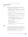
Drawing/Painting Layout
The Box
MAX makes extensive use of a rectangular box, displayed in brown (by default) on the
screen. The Box is a sort of second cursor that designates an area rather than a point. Many
MAX commands work on the area defined by the Box.
For example, the normal way to add a rectangle on a layer is to place the Box where
the rectangle is to go, and then click with Button-3 (right mouse button) over a sample
of the layer you wish to draw.
You can also draw polygons and circles (See “Add Polygon” on page 59) with MAX.
To paint a rectangle on a mask layer in MAX,
Move the Box to the rectangle you want to paint (See “Make/move Box” on page 94),
and then click over a sample of the layer you wish to paint with mouse Button-3 (in
Main mode).
If there is no sample handy in the Layout Window, you can click over a palette entry
instead with mouse Button-3.
Notice that multiple layers can be painted at once, and that only layers that are
currently visible (turned on in the palette) get painted.
You can also use Button-3 to erase all mask layers under the Box, by clicking on
empty space; or click Ctrl-Button-3 over a layer to erase just that layer.
To change the layer of a rectangle:
First select the rectangle,
Erase that layer by clicking over empty space and then
Select a new layer with Button-3.
You can also use the Edit Properties (page 67) command (hotkey: p) to change
the layer of a rectangle.
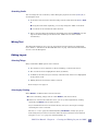
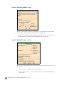
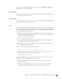
Gcells
Generator cells or Gcells are parameterized cells that regenerate themselves when they get
different inputs. Devices (such as fets) and vias are good candidates for Gcells since a given
layout may have multiple types that differ only by size or some other attribute.
Gcells are user definable using the Tcl scripting language. Presently they must be created
and modified using a text editor. To discern Gcells from conventional MAX cells, Gcells are
saved in .maxg files as opposed to .max files.
Refer to Gcells Tcl Programs (page 155) for information on creating Gcells.
MAX User Manual - Chapter 2 -- Creating and Editing Layout with MAX
25
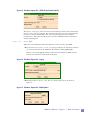
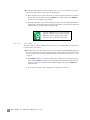
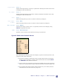
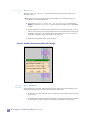
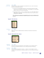
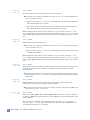
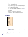
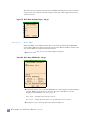
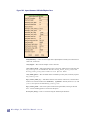
To insert a Gcell into the layout, click on it with Button-1 (left mouse button) in the
cell list on the right side of the MAX window. This will bring up the Gcell Edit
Properties form (See Figure 6).
Currently MAX comes with fet and via generators. The Edit Properties form for a
fet allows you to change the width, length, number of fingers and location of the
contacts.
Once you have specified the properties, click on Done.
You can rotate (hotkey: r) or flip (hotkey: x or y) the fet before you place it.
Move the fet to the desired location and click with Button-1. The Wiring Tool
automatically drops via Gcells.
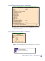
You can edit the properties of a Gcell with the Push into Cell (page 79) command in the
Edit menu (hotkey: e). This will bring up the Edit Properties form (See Figure 6) for
the selected Gcell.
Figure 6: FET Gcell
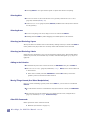
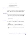
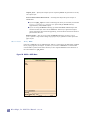
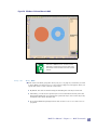
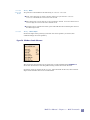
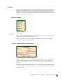
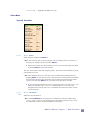
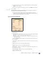
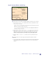
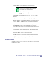
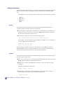
There is also a Gcell for text as show in Figure 7. This can be used to add text, such as the
company name or chip name, to the layout.
Figure 7: Text Gcell
26
Micro Magic, Inc. MAX User Manual -- v5.1.12
Stretching Gcells
You can change the size of a Gcell by either editing the properties of a Gcell (hotkey: e) or
stretching the Gcell.
To stretch a Gcell, first select the Gcell and go into the Gcell edit mode (hotkey: Shift-
e).
Using the Gcell stretch capability, you can only change the width of a fet Gcell.
A via Gcell can be stretched in either direction.
Once in the Gcell edit mode, hold down the middle mouse button (Button-2) near the
edge of the Gcell and drag to the desired size. Additional vias will be added
automatically.
Wiring Tool
The Wiring Tool makes it easy to lay out wires which include contacts/vias and multiple
layers. Refer to “Introduction To The MAX Wire Tool” on page 109 for detailed information
on how to use the Wiring Tool.
Editing Layout
Selecting Things
Many commands in MAX operate on the selection.
For example, to move, duplicate or delete something, you must first select it.
The current selection is highlighted in white (by default).
In addition, the names of layers currently contained in the selection are highlighted
in the palette in red.
Editing functions are based on what is selected.
Refer to Figure 3 on page 13.
Selecting by Pointing
Mouse Button-1 (in Main mode) is used for selection.
To select something, simply click on it with Button-1 (left mouse button).
If there are several items under the cursor, you can cycle through them by clicking
repeatedly with Button-1 at the same location.
Layers and labels/text can be selected in this way. For layers, the largest rectangle
containing the cursor is selected.
The Cursor Probe (page 93) command (hotkey: Ctrl-Button-1) brings up a pop-up
form listing all layers, Gcell or instances under the mouse. Instances can be selected
using the Select Cell (page 91) command (hotkey: f).
MAX User Manual - Chapter 2 -- Creating and Editing Layout with MAX
27
Clicking Button-1 on a space with no paint or objects will deselect everything.
Selecting Nets
To select an entire net, move the mouse over a geometry and use the Select Net
(page 92) command (hotkey: s).
In the Cursor Probe (page 93) form, Button-2 (middle mouse button) selects the net
for the geometry.
Selecting Areas
To select everything in an area, drag a box over it with mouse Button-1.
Holding down the Shift key while dragging a box adds objects to the selection.
Selecting (and Excluding) Layers
The layers that are selectable can be controlled by clicking on the layer name with Button-1
in the palette. Only layers that are currently visible and selectable can be selected.
Selecting (and Excluding) Labels
Labels that are attached to a layer are selected along with the layer. Free floating labels
(with no layer below) are selectable only if visible, controlled through Display Options
(page 42).
Adding to the Selection
To add more objects to the current selection, use Shift-Button-1 in place of Button-1.
The Selection Probe (page 92) command (hotkey: Shift-f) can be used to add a cell
to the selection.
If the item is already selected, Shift-Button-1 and the Alt-f hotkeys remove the
geometry, Gcell or instance from the selection.
Moving Things Around (And Other Manipulations)
Once you select something, typically with mouse Button-1, you can move it around with
Button-2.
To constrain the motion to one dimension only (horizontal or vertical) use Shift-Button2.
The selection can also be stepped over, one design-grid at a time, using the Move
(page 71) command (hotkeys: Shift-arrow-keys).
Other Edit Commands
Other operations on the selection include:
Rotations (See “Rotate” on page 71),
28
Micro Magic, Inc. MAX User Manual -- v5.1.12
Flips (See “Flip Upside-Down” on page 71),
Stretching (See “Stretch” on page 75),
Duplication (See “Duplicate” on page 70) and
Deletion (See “Delete” on page 70).
These operations can all be found in the Edit Menu (page 57).
Hierarchy
Each cell in MAX is saved as a separate ASCII file on disk. A cell contains geometries and/
or instances. In order to place an instance of a cell, it must be first loaded into MAX. If you
have a standard cell library where all layout cells are in one directory, use the
max_auto_load text command to load all cells in a directory. This command can be put
into your .maxrc file.
Placing instances
To place an instance in the current edit cell, you need to have first loaded the cell into MAX.
Once it is in one of the cell lists you can place the instance by holding down the Shift
key while clicking on the cell with mouse Button-1.
You then use Button-1 in the Layout Window to position the instance.
You can use the Duplicate (page 70) command (hotkey: d) to place multiple
instances of the same cell.
Editing in place
Once you have placed instances in a cell, you can edit the lower level cells using the Edit
Cell or Object in Place (page 80) command (hotkey: Shift-e) to edit the cell while
viewing the rest of the layout.
The command Push into Cell (page 79) (hotkey: e) pushes you down into the cell
for editing.
The command Pop out of Cell (page 80) (hotkey: Ctrl-e) pops you back up.
To use the Edit Cell or Object in Place or Push into Cell commands, you must
first select the instance.
Use the Select Cell (page 91) command (hotkey: f) to select an instance of the
cell.
MAX User Manual - Chapter 2 -- Creating and Editing Layout with MAX
29
30
Micro Magic, Inc. MAX User Manual -- v5.1.12
Chapter
3
MAX Commands
MAX Menus
This section describes each menu item in the MAX Layout Editor. A brief description of
each command is displayed in the MAX Message Area (page 12) when the cursor is over the
menu item. (Before reading this chapter, it is a good idea to have run the MAX Tutorial
and/or read Chapter 2.) Each menu item is described starting with the File menu on the
left.
File Menu
This menu is used create and open cells, save cells, import and export GDSII, and so on.
Each menu option is described below.
Figure 8: The File Menu
New
Hotkey: Ctrl-n
This is used to create a new cell. A form will pop up (see Figure 9) where you can specify the
path and name of the new cell. Until the cell is saved for the first time, it is only in memory
and has not been created in the UNIX file system. The first time a file is saved, a file
<cell name>.max will be created in the specified directory. All MAX files must have the
.max extention.
Chapter 3 -- MAX Commands
31
Figure 9: File Menu: New... Create a New Cell Pop-up
Open
Hotkey: Ctrl-l
Open an existing cell. A directory navigator box similar to Figure 9 comes up which allows
you to search for the desired cell.
Save
Hotkey: Ctrl-s
Save the current cell. The cell is saved in a file called <cell_name>.max in the directory
from which it was opened or created (New). If the cell is UNNAMED, a pop-up box (see
Figure 10) appears where you specify the path and cell name.
Save As
Hotkey: None
Save the current cell to a different name. The cell is saved to the new name and MAX opens
the new cell. The original cell will not be updated.
32
Micro Magic, Inc. MAX User Manual -- v5.1.12
Figure 10: File Menu: Save As... Pop-up
Save Multiple
Hotkey: None
This command brings up a sub-menu allowing you to save multiple cells. The options are:
Save edit cell and descendents — Save the current cell (edit cell) and all cells in the
hierarchy below the current cell (descendents). This only saves cells that have been
modified.
Save all modified cell buffers — Save all cells currently open in MAX which have
been modified.
Save all cells — Save all cells in memory (loaded into MAX) except UNNAMED. This
will save cells whether they have been modified or not.
Revert to
Last Saved
Hotkey: None
Copy Cell
Buffer
Hotkey: None
Delete Cell
Buffer
Restore current cell to the version which was last saved to disk. The user is prompted if this
should really be done.
Make a copy of the current cell. This copies the existing version of the cell in memory to a
new cell. The new cell must be saved in order for there to be a <cell_name>.max file on
disk for the cell. This is used if you want to save the current state of the cell you are editing
into a different cell name.
Hotkey: None
Delete the edit cell buffer (the cell you are currently editing). This only affects the version of
the cell in memory. The version on disk, the <cell_name>.max file, remains unchanged.
MAX User Manual - Chapter 3 -- MAX Commands
33
Change Path
of Cell
Hotkey: None
Load Cell
Hierarchy
Hotkey: None
Edit Cell
Path
Hotkey: None
Change directory where current cell will be saved. The default is the location from which it
was loaded.
Load current cell's descendents into memory. This can also be accomplished by Showing
internals, which first has to load all the subcells in order to view them.
This menu allows you to more easily manage various directories. You can add, delete, and
reprioritize directories. These are the directories where MAX will look for cells or gcells
that are instantiated. It looks in the first directory first and if not found, looks in the next
directory.
Figure 11 shows two directories, the directory from which MAX was started and the gcell
directory. If you add new directories, these directories will not be displayed in the list boxes
until a cell is loaded from the directory. Generally this command is added to your .maxrc
file using the cell_path_add text command. That way if you have one cell that calls cells
from other directories, they can be found.
Figure 11: File: Edit Cell Path
When you click Done, all cells in those directories that you have deleted will be removed
from MAX memory.
Toggle Read
Only
Hotkey: None
Import File
Hotkey: None
Toggle the read-only status of the current edit cell. If the cell is not read-only, this makes
the cell read-only, and vice-versa.
This brings up the Import File pop-up shown in Figure 12, allowing you to import a file
into MAX. Currently only GDSII files are supported. The GDSII Import Setup Options
menu is described below.
34
Micro Magic, Inc. MAX User Manual -- v5.1.12
Figure 12: File Menu: Import File... Pop-up
If you click on Find, a File select box appears. If there is an existing cell in memory
with the same name as a cell in the GDSII file, it will be overwritten by the Import File
command. This will not affect the version of the cell saved on disk.
The default suffixes for GDSII files are
.gds, .strm, or .gdsii. You may need
to change the suffix in the file selector box to
find the GDSII files if your suffix is
something else.
Clicking on GDSII Import Setup Options brings up the pop-up shown in Figure 13. Each
of the options are described below:
Figure 13: File Menu: Import File... GDSII Import Options
MAX User Manual - Chapter 3 -- MAX Commands
35
input style — If the technology file contains multiple styles, you can select between
styles. In general there will be only one input style.
scale factor — While reading in the GDSII, the layout can be scaled by the specified
factor. The default scale factor, 1.0, does not scale the layout.
read only specified cells — This allows you to read only a single cell or a cell and its
descendents, not the entire GDSII file. Once you click on Done, MAX searches the
GDSII file for all cell names and brings up the pop-up as shown in Figure 14. You can
then select the cell to load from the generated list as well as specify whether to load its
descendents.
Figure 14: File Menu: Import File... Import Options Cell List Pop-up
set to drc clean — Do not check for DRC errors once the GDSII file has been read in.
You generally want this to be selected because running MAX DRC on an entire chip or
block can take quite a while. When you make edits in MAX, the DRC rules will be
checked in the area near the edits only.
snap to grid — Snap all coordinates in the layout to the grid specified. The default is
the design grid.
convert cellname case — Convert cell names to all uppercase, all lowercase or leave
them as is (default).
report rounding errors — Report rounding errors when reading in a GDSII file.
Rounding errors can occur when converting from GDSII units to internal MAX units.
They can also happen when snapping to a user grid, or when scaling (both GDSII input
options).
report unmapped layers — Report any data found in the GDSII file on layers for
which there is no definition (mapping) in the MAX technology file.
report duplicate instances — Report if duplicate instances are found at the same
location. This should generally be turned off if the GDSII has lots of duplicates of cells
at the exact same location (such as via cells).
All of the above options assume that there is an existing MAX technology file which
matches the GDSII file. If no technology file exits, click on Create tech file from GDS
file and the form will update to look like Figure 15.
36
Micro Magic, Inc. MAX User Manual -- v5.1.12
Figure 15: File Menu: Import File... GDSII File and Create Tech File
The Output Technology name is the name of the technology which will be created using
the gds_input (page 131) program. The technology file will be very basic with mappings
for layers. It will not include DRC rules, but is a good starting place for creating a
technology file. This option also allows you to look at a GDSII file without requiring an
existing technology file.
Export File
Hotkey: None
Export the current MAX cell and its descendents to a file, currently only GDSII.
If you click on Find, a File select box pop-up (see Figure 16) will appear, allowing
you to specify the name of the GDSII file. The default is <cell_name>.gds.
If there is an existing .gds file with the same name in the directory, MAX will first
have the user confirm overwriting the existing file.
Figure 16: File Menu: Export File... Pop-up
Clicking on GDSII Export Setup Options, brings up the pop-up as shown in
Figure 17.
Figure 17: File Menu: Export File... GDSII Options
MAX User Manual - Chapter 3 -- MAX Commands
37
output_style — Specify the output style for exporting GDSII. In general there is only
one output style.
Process hierarchical interactions — Turning this off speeds up the output of
GDSII data.
If you used gds_input to create a technology file, then you can safely turn off the
Process hierarchical interactions option and get MUCH faster (by
approximately 100x) GDSII output.
If you are using the mmi25 technology provided with MAX, GDSII output does
much more than just write out the GDSII file. It does layer generation (nplus,
pplus, and nwell) with notch and gap filling, so hierarchical interactions must be
processed in this case.
Flatten gcells — Also, if you are using the mmi25 technology, use the Flatten
gcells option to tape out the design to get proper layer generation of the nplus and
pplus layers.
GDSII->ASCII
Hotkey: None
Converts a GDSII file into an ASCII format. This is a useful option for debugging a GDSII
file. A pop-up appears (see Figure 18) where you can select a GDSII file to convert. This
converted file is placed in the same directory as the original GDSII file. The extension of
the converted file is .gds_ascii.
Figure 18: GDSII -> ASCII Menu
38
Micro Magic, Inc. MAX User Manual -- v5.1.12
Print
Hotkey: None
Using the Print command in the File menu, MAX prints the current cell to a postscript
printer.
MAX prints all layers that are currently visible in the layout with the same colors, outlines,
and stipples as set in MAX.
Adjust colors and fill patterns before printing using the Color Editor (page 41) under
User Preferences in the File menu.
Additionally, turn off any layers in MAX that you do not want to plot.
For example, to plot only metal layers, turn off all other layers in the MAX palette
before running the Print command.
MAX prints the entire cell, including all hierarchy shown, despite what is visible on the
screen.
To see what will be printed, do a Zoom to Fit Edit Cell (page 82) (hotkey: v), and
then move the mouse outside of the cell and Select Cell (page 91) (hotkey: f).
Once the top level cell is selected, select Internals, View All (page 82) (hotkey: i).
Before printing, MAX brings up a Postscript Print Setup Form (see Figure 19) where
you select the printer (print command to use), the size of the plot, its orientation, the font
scaling, a title, and whether to print directly or to a file. Even if you print to a file, you must
choose the eventual printer name and image size so MAX can create the appropriate file
type.
Figure 19: File Menu: Print... Setup Options
If the Image Orientation is set to largest, MAX automatically selects the orientation
which will give you the largest printout. You can also select the standard landscape and
portrait orientations.
MAX User Manual - Chapter 3 -- MAX Commands
39
For plotters, you can specify the length and width by entering values in the page_x and
page_y fields.
For example, if your plotter has a carriage width of 36 inches and you want a 70 inch
long plot, you would specify “page_x 36” and “page_y 70”.
in the “print_command” field you can type in direct commands to plot, like this:
cat %s | lpr -s -P%p
where %s is replaced with the plot file name and %p is replaced with the printer/plotter
name when printing.
After the plot is complete, the plot file is removed..
Why not use the simple command:
lpr -P%p %s
In short, because plot files can get very large, the -s option is required to prevent the
plot file from being copied to the print queue and possibly overflowing or jamming it.
Unfortunately, you must be careful to not delete the plot file until the plot is completely
sent to the plotter. By using the cat command, this is partially insured.
Even with this command, you may still have
to plot large plots to a file and then send
them to the printer.
User
Preferences
Hotkey: None
This brings up a sub-menu (see Figure 20) allowing you to specify user options. Each of
these options are described below.
Figure 20: File Menu: User Preferences Options
40
Micro Magic, Inc. MAX User Manual -- v5.1.12
Color Editor
Hotkey: None
This brings up the MAX color editor as shown in Figure 21. You can specify the color and
fill/stipple pattern for each layer.
Figure 21: File Menu: Color Editor... Pop-up
Hold down Button-1 over Edit layer at the top of the pop-up to select a layer to edit.
The layers to edit include the background, highlight, feedback (external DRC tools)
and grid layers.
You specify the color using the HSB or RGB sliders.
You can select a specific color name by holding down Button-1 over Colors.
In the lower section, you can specify whether to use a solid or stipple fill for the
layer.
The solid fill is a transparent color and is typically used for poly and metal layers.
If you select stipple, you can choose from one of the predefined stipple patterns, or
create your own. You may also select a solid outline for a stippled layer.
For each via layer you can specify via styles, what kind of “x” to put over it. This allows
you to set different via styles for different layers.
MAX User Manual - Chapter 3 -- MAX Commands
41
You can specify a file to load or save the color information to. The default is always ~/
mmi_private/max/tech/<tech_name>/<tech_name>.override. If it is saved in
this file, then the color information will automatically be loaded the next time you start
MAX as the same user.
To revert to the original colors and fill types, click on the Revert button and the pop-up
in Figure 22 will appear.
Figure 22: File Menu: User Preferences Color Editor... Revert Colors Form
If you choose Start-up Defaults, colors will be reset to what they were when you
started this MAX session, or from the last time you saved the colors in this session. You
can choose to revert all colors to these default settings or only the color that is
currently in the color/stipple editor.
If you choose System Defaults, MAX removes all your personal color preference
settings by deleting any color file in ~/mmi_private/max/tech for this technology.
All colors will be reset to the defaults specified in the system tech file.
If you select Save in the Color Editor, you current settings for all layers will be saved
in your mmi_private directory in ~/mmi_private/max/tech/<tech_name>, where
<tech_name> is the name of the current MAX technology. MAX loads these color
settings the next time you bring up MAX with this technology.
Display
Options
42
Hotkey: Shift-o
This brings up a sub-menu allowing you to specify user options, as shown in Figure 23.
Each of these options is described below.
Micro Magic, Inc. MAX User Manual -- v5.1.12
Figure 23: File Menu: User Preferences Display Options... Pop-up
Show Palette — This is a toggle button to turn on or off viewing of the palette on the
left side of the MAX window.
Show Cell Lists — This toggle button turns on or off the viewing of the cell lists on
the right side of the MAX window. If the cell lists are turned off, the Navigator Window
is also turned off.
Show Navigator Window — This toggle button turns on or off the viewing of the
Navigator Window on the right side of the MAX window. The cell lists will expand
down into the region reserved for the Navigator Window.
Show Bottom Bar — This toggle button turns on or off the bottom bar containing the
DRC Status Area, the Zoom Bar, Cursor Coordinates and the Box Display Area.
Show Scroll Bars — This toggle button turns on or off the scroll bars on the bottom
and right of the edit area. The scroll bars appear only when you are zoomed in on the
layout.
Dim Non-Edit Cells — Normally mask information that is not in the edit cell is
dimmed. To display all mask information at the same brightness, turn this button on.
Merge — Paint is rectangles or polygons in a specific layer. This controls what
happens when you merge paint. Paint merging, which provides correct alpha blending
and outlining for layers works for both rectangles and polygons. This controls how
overlapping polygons and rectangles are viewed in MAX.
MAX User Manual - Chapter 3 -- MAX Commands
43
There are three Merge Paint options, controlled in the Display Options menu.
Show individual rectangles/polygons: If paint merging is set to this, then
MAX shows the individual rectangles and polygons. If there are two rectangle of
the same layer in the same cell and same hierarchy, the the rectangles are always
merged and look as if they are a single polygon. If a paint rectangle and a polygon
overlap, then this option will show the overlap area in a darker shade than the
layout layer color.
Merge all paint: This causes all paint and polygons to be merged across all cells.
All rectangles and polygons will be shown with the same shade of color.
Remember, though, that the current edit cell is always displayed in a darker shade
unless the Dim Non-Edit Cells options is turned off.
Merge paint in each cell individually: This causes paint to be merged for each
subcell individually.
Show Flylines — Flylines show connections yet to be wired, as straight lines between
the circuit elements to be connected. The display of flylines is controlled by this toggle
button. Flylines are only visible when you are zoomed in closely enough.
Box stipple pattern — This controls the outline pattern for the box layer. In the
Color Editor, you can only change the color of the box. The options for the outline are
solid, dash, and dotdash. Use the toggle list to select the desired option. You can also
specify your own stipple pattern, for example for a dash pattern, use 0377. Stipple
pattern is a 16-bit binary number where a 1 means the pattern is on and 0 means it is
off.
Show Selected on Layers Only if Visible — If this is toggled on, then when you do
a select net, only layers which are visible are highlighted. Select net still traces the
connectivity through layers which are not visible.
Show sub-cell comment and local Text (labels) — This toggle button turns on or
off the viewing of comment labels and local labels in a hierarchical design. If labels are
defined as input, output, inout, or global they will always be displayed if labels is
turned on and the internals are visible. By default, any labels which are comment
labels or local labels and are in lower level cells, are not visible.
To make these labels visible the Show sub-cell comment and local Text
(labels) toggle must be turned on. Note that these Text types are always
displayed in the edit-cell.
For sub-cells with internals hidden: - When internals are hidden or not shown,
there are the two display options below.
Show cell instance names — Normally subcell names and instance identifiers
are displayed for subcell instances whose internals are hidden. If this button is
turned off, these names will not be displayed. The subcell names will still be
displayed if the subcell is selected.
Show ports — Show/hide Text ports (Text of types “input”, “output” or “inout”)
even when sub-cell internals are hidden.
Text Size Factor — This controls the zoom level where Text labels disappear. Larger
numbers make Text labels more visible when zoomed out.
44
Micro Magic, Inc. MAX User Manual -- v5.1.12
Layer Transparency — Controls the transparency of layers in the edit cell. The
values are a percentage of “solid”, where 100% would be completely opaque, and 0%
would be completely transparent (invisible). Transparency is generally most useful
with values of 0.40 to 0.80, or 40% - 80% opaque.
Dim Percentage — Controls the transparency of layers that are not in the edit cell.
The transparency is a percentage value of opaqueness of the specified layer, as
explained above.
Flatten Setup
Hotkey: None
This menu controls setup for the Flatten Cells (page 98) command, accessible through
the Misc menu. The setup menu specifies what happens to labels in a cell when you flatten
it.
For each type of label or text (input, output, inout, global, local, comment) you can
either:
Delete that type of label/text, or
Change it into any other type of label.
For example:
If you specify global turns into: global then global labels in the flattened cell
will be copied into the parent cell without changes.
If you specify global turns into: delete, then global labels will be deleted.
You can also specify whether to flatten or preserve the label names. If they are preserved,
they may conflict with other existing labels with the same name.
To avoid this, you can flatten the label names, which will cause the labels to be
renamed to something like: cellname.labelname where cellname is the instance
name of the cell that was flattened, and labelname was the label name in the cell that
was flattened.
Cell Ids — If set to “flatten”, Cell Id names are flattened by prepending the name of
the parent cell to the cell’s name. If set to “preserve”, the Cell Ids are retained, but
may be made unique by appending “_n”, where n is a number.
Hierarchical name sep — this field allows you to enter a label to differentiate cell
names within a hierarchy, such as “.parent” or “.secondary”. These names will
automatically be appended to the cell name.
MAX User Manual - Chapter 3 -- MAX Commands
45
Figure 24: File Menu: User Preferences Flatten Setup... Pop-up
General Setup
Hotkey: None
This brings up a sub-menu, shown in Figure 25,which allows you to specify user options.
Each of these options are described below.
46
Micro Magic, Inc. MAX User Manual -- v5.1.12
Figure 25: File Menu: User Preferences General Setup... Pop-up
Warp Cursor to Menu — If set, the mouse cursor will move automatically (warp) to
the default “OK” or “Done” button within most pop-up menus. Be aware that this
option may not work if you are using a Linux emulator.
Raise Menus on Mouse Click — If set, then clicking the mouse anywhere in the
MAX window will automatically raise and make visible the current property menu or
dialog box. For times when a property menu or dialog box is obscured by the main MAX
window; that is, when the menu drops behind the main MAX window in the window
stacking order and is no longer visible, this is a helpful option.
SELECT NET OPTIONS — These next two options apply to selected nets and how
net names are displayed.
Display selected text — When you select a net, this displays all unique text on the
net, which can be a very long list. But it can be a very useful option if trying to detect
shorts. If a net has both a VDD and a GND label on it, then you know there is a
problem.
Display hierarchical paths for text — When you select a net, this will include
hierarchical text names in the list of selected text. Otherwise, it will only list the
names in each cell, which could be confusing in some cases. You would want to turn
this option off though if you’re looking at global signals such as CLK.
DOCUMENTATION OPTIONS — These options control which text and html editors to
use for displaying documentation.
Text editor — This is used to specify the default text file editor for Display Cell
Doc (page 84) in the View menu. The default is emacs.
Default text file suffix — This is used to specify the default text file suffix for
Display Cell Doc (page 84) in View menu. This defaults to .doc.
Html browser — This is used to specify the default HTML file browser for Display
Cell Doc (page 84) in View menu. The default is firefox.
Default html file suffix — This is used to specify the default HTML file suffix for
Display Cell Doc (page 84) in View menu. This defaults to .html.
MAX User Manual - Chapter 3 -- MAX Commands
47
Grid Setup
Hotkey: Shift-g
This command opens a pop-up form as shown in Figure 26. There are both a coarse grid
and a fine grid which can be defined and viewed separately. In addition, the grid can be
displayed as either lines (default), dots or dashes.
Figure 26: File Menu: User Preferences Grid Setup... Pop-up
Grid Number — MAX maintains information for several different grids. This option
controls which grid is the current grid. The information on the current grid is displayed
in this menu. You can set up the grids differently and then switch between them
rapidly using this menu, or using hotkeys. (The default hotkeys are: 1, 2, 3, 4.)
Grid visibility — Determines if visible grid is currently on or off. Can be changed by
the Toggle Grid (page 81) command in the View menu.
Specify Grid Set Up — If set to normal, the basic grid options are displayed in this
menu. If set to detailed, additional available grid options are displayed.
Grid Name: — Allows you to enter a discriptive name for this particular grid setup.
User Design Grid — Points and rectangles entered by the mouse will snap to this
resolution.
coarse visibility — Show a coarse grid when grid is on and zoomed in far enough. The
grid can be displayed as either lines, dots or dashes.
coarse grid size — The size of coarse grid, if visible.
48
Micro Magic, Inc. MAX User Manual -- v5.1.12
fine visibility — Show a fine grid when grid is on and zoomed in far enough. The grid
can be displayed as either lines or dots.
fine grid size— The size of fine grid, if visible.
Manufacturing Mask Grid — The minimum feature size determined by the
manufacturing process; this value is set in the tech file See “Technology Source
Files” on page 134.. and cannot be changed here. It is listed for reference.
Edit Wiring Preferences — This brings up the Wiring Parameters popup menu, as
detailed in Wiring Tool chapter. This is where you can change the width, spacing
and grid for use with the Wiring Tool.
If Specify Grid Setup is set to detailed, the following additional options are displayed
as shown in Figure 27.
Figure 27: File Menu: User Preferences Grid Setup... Detailed Grid Setup
User Design Grid X — Points and rectangles entered by the mouse will snap to this
resolution in the X direction.
User Design Grid Y — Points and rectangles entered by the mouse will snap to this
resolution in the Y direction.
MAX User Manual - Chapter 3 -- MAX Commands
49
coarse visibility — The coarse grid can be turned off, or be lines, dots, or dashes.
The coarse grid is displayed when you are zoomed out far enough.
coarse grid size X — The size of coarse grid in X direction, if visible.
coarse grid size Y — The size of coarse grid in Y direction, if visible.
coarse grid origin X — The origin of coarse grid in X direction.
coarse grid origin Y — The origin of coarse grid in Y direction.
coarse dot size — The size of grid dots if grid type is dots.
fine visibility — The display type of the fine grid. This can be set to either lines or
dots, dashes or turned off.
fine grid size X — The size of coarse grid in X direction, if visible.
fine grid size Y — The size of coarse grid in Y direction, if visible.
fine grid origin X — The origin of fine grid in X direction.
fine grid origin Y — The origin of fine grid in Y direction.
fine dot size — The size of grid dots if grid type is dots.
Hot-Keys
Hotkey: None
This brings up a pop-up form, shown in Figure 28, where you can view, specify or modify
the hotkey bindings used in MAX.
The Edit Keymap pop-up lists the menu entries and commands with reprogrammable
hotkeys.
The left column contains a description of the menu or command.
The right column shows the current hotkey binding, and is empty if no hotkey is
assigned.
Some hotkeys can not be changed (for example, Ctrl-C), and so those menu items do
not appear in the list.
The hotkeys can either be displayed in Menu Order if you’re looking for a specific
command from a menu, or they can be displayed Alphabetical by HotKey. This is
helpful if you’re trying to find out what hotkeys have already been defined.
50
Micro Magic, Inc. MAX User Manual -- v5.1.12
Figure 28: File Menu: User Preferences Hot Keys... Edit Keymap Pop-up
To edit the hotkey for a command, click on the item with Button-1 and a pop-up form
appears as shown in Figure 29.
Figure 29: File Menu: User Preferences Hot Keys... Edit Key Bindings
Hot-Key — The hotkey designation can be be any single character (a-z, 0-9, or symbols
like $ or %), a function key designator (F1 - F10 only, not F11 or F12) or a valid
“keysym” name for special keys on your system, such as “Left” for the left-arrow key.
CASE IS IMPORTANT!
“Left” is not the same as “left”.
MAX User Manual - Chapter 3 -- MAX Commands
51
To remove a hotkey binding, leave the entry blank.
Valid keysym names vary from system to system and can be difficult to discover. Use
the pop-up menu on the right edge of the Hot-Key: entry area to display a list of
possibly valid keysyms.
Sometimes the symbolic key you select (such as “<“) will automatically be converted to a
keysym name (like “less”) to make sure it will be a valid binding for the X-window system.
Many keys have multiple keysym names; MAX does not detect conflicts if you use
synonyms. For example, if you bind the hotkey “%” to one function and “percent” (a valid
keysym name synonymous with “%”) to another function, no error will be printed.
Obviously, the % hotkey will perform only one of the two functions.
Modifier — The modifers can be Shift, Control or Alt. If you want a hotkey to be a
capital “b”, then specify the hotkey as b and the modifier as Shift.
The “Alt” key modifier is pre-empted by some window managers and not passed to
application programs, so it may not be usable in MAX. MAX automatically maps all “Alt”
key combinations to “Meta” key combinations as well, so if you create a hotkey using the
“Alt” modifier, you may be able to use the hotkey combination by pressing the “Meta” key
(if you have one) instead of the “Alt” key.
If you want to Save or Load a keymap file, you first enter the file name in the File:
box. You can use find button to help search for a file. The default location for a user
defined keymap is ~/mmi_private/max/default.keymap. If this file exists, then it
is automatically loaded when you start MAX. After specifying the file name, click on
Save or Load to save or load the file.
At any time you can Revert to factory default keymap. This reverts back to the
hotkey settings that came with MAX.
The keymap files are found in the following places and loaded in this order.
$MMI_TOOLS/max/
$MMI_LOCAL/max/
~/mmi_private/max/
The final keymap loaded overrides the others.
System administrators can add keymaps to this list by creating and saving a keymap
in MAX, then copying their file ~/mmi_private/max/default.keymap to
$MMI_LOCAL/max/new.keymap, where "new" is a descriptive name of the keymap.
If you select Done, the new hotkeys will be used in the current MAX session. The new
hotkeys will appear in the help for Current Hot Keys, and will also appear in the
menus.
Layout
Generator
Setup
Hotkey: None
This brings up a sub-menu allowing you to specify user options, as shown in Figure 30,
below. These are options which are used by the Layout Generator which is part of MAX-LS.
Each option in this menu is described fully in Chapter 5, "Introduction To The MAX Layout
Generator".
52
Micro Magic, Inc. MAX User Manual -- v5.1.12
Figure 30: File Menu: User Preferences Layout Generator Setup... Pop-up
Ruler Setup
Hotkey: None
This brings up the Ruler Setup pop-up form, shown in Figure 31, which controls how the
ruler snaps and whether to user absolute or relative coordinates.
Figure 31: File Menu: User Preferences Ruler Setup... Pop-up
Ruler Snap To — This specifies what the ruler will snap to. The options are Exact
Point (the exact point you click on), User Grid (the nearest user grid point), Nearest
Edge (The nearest edge of any polygon), or Alternate Ruler Grid.
Alternate Ruler Grid — The alternate grid, in microns, as opposed to the User Grid.
This is only used if Ruler Snap To is set to Alternate Ruler Grid.
Ruler Coordinates — If set to relative, the ruler is numbered starting at 0. If set to
absolute, the ruler is numbered with absolute coordinates.
Ruler Font Size — The size of text displayed by the ruler. This option does not affect
rulers that have already been drawn.
Clear Ruler Now — Clears all rulers. You can also use the Alt-r hotkey.
MAX User Manual - Chapter 3 -- MAX Commands
53
Wire Setup
Hotkey: Shift-w
The Wire Setup menu (see Figure 32) contains several options for controlling wiring
parameters. These options are described below.
Figure 32: File Menu: User Preferences Wire Setup... Pop-up
Active Layer — This is the layer the wire tool uses to draw the wire. If the tool is set
to auto, the wire tool attempts to determine the correct layer by looking under the
mouse when the wire is started. If there are multiple layers under the mouse, it uses
the top layer. The Active Layer can also be set using the Active: indicator at the
upper left of the MAX screen.
Default Layer — Sets the first layer the wire tool looks for under the cursor if Active
Layer is set to auto, and either the Default Layer is found under the cursor, or there
are no layers under the cursor.
Manhattan Endcaps — This is used only for drawing Manhattan wires. It can be set
to both, none, begin, or end. If set to “both”, then the wire will be drawn with
beginning and ending endcaps with a size half the width of the wire. So, the wire will
extend half a wire width past the beginning and ending points.
Snap to Wire Grid: — Wire end-points and vertices will snap to the wiring grid
specified in the Wiring Parameters menu. This is NOT the same as the User Grid in
the Grid menu. You can specify a different wiring grid for each layer being wired in the
Wiring Parameters menu. When placing a via, the via will be moved to the nearest
valid intersection of the grids of the two layers being connected by the via.
Snap to Angle — Wires are constrained to the specified angle. If the angle is set to 0,
all angle wiring is allowed. The Snap to Angle can be 90. 45, 30, 15, or 0 degrees.
54
Micro Magic, Inc. MAX User Manual -- v5.1.12
Draw Vias Using — If set to any, the code draws vias using the first method that
works.
If there is a via gcell installed, that will be used;
If there is a via sub-cell found, that will be used;
As a last resort, vias will be painted using rectangles.
You generally want to use the gcell option.
Via gcell name — Specify the name of gcell to use for vias, and default properties in
the form of: -propname value. This is used only if Draw Vias Using is set to any or
gcell. You can use this to specify default properties for the via. For example, to make
vias symmetric by default, set it to: via -symmetric 1. You can also change this if
you have created your own via gcell for use by the wiring tool. To force the wiring tool
to use 2 vias when changing layers, use the gcell name: via -min_x_cuts 2.
Flylines follow mouse — If this is set, any flylines attached to the net being wired
will follow the end of the wire. When the wire is connected, the flylines disappear.
PERFORMANCE WARNING: If this option is set, and
there are any flylines anywhere in the edit cell, then
the wire tool will trace the wire connectivity, using the
sel_net function, each time a new wire is started.
If the wire is extensive (example: vdd or gnd), and the
cells through which the wire is connected are currently
expanded (ie, their contents are visible), then the wire
tool may be slow.
Display spacing box — A visible spacing box will be displayed showing the current
spacing of the wire being drawn. The spacing info is taken from the Wiring
Parameters menu. This can be helpful if the wiring spacing rules are larger than the
DRC spacing rules.
Check connectivity — If this is set, MAX will check wire connectivity when the wire
is finished, and report any shorts. Connectivity is not traced through unexpanded cells;
only conflicts among labels in the edit cell are reported.
PERFORMANCE WARNING: If this option is set, the
wiring tool will trace the wire connectivity using the
sel_net function, which can be slow if the wire is
extensive (for example, vdd or gnd).
Bus Width — If you are wiring busses, then this is the width of the busses.
Bus Origin — If the origin is set to top/left, the bus is built downward or to the right of
the cursor. If the origin is set to bottom/right, the bus is built upward or to the left of
the cursor.
MAX User Manual - Chapter 3 -- MAX Commands
55
Edit Wiring Parameters — Edit the parameters for the wiring tool. See Wiring
Menu (page 113) for detailed information on the wire parameters. This is where you
specify the width, spacing, and grid for each layer for use in the wiring tool.
Save/Revert
Options
Hotkey: None
This saves the current settings for the colors, grid, ruler, and so on, to the file:
~/mmi_private/max/tech/<tech_name>/<tech_name>.pref.
The palette information will be written to a separate file:
~/mmi_private/max/tech/<tech_name>/<tech_name>.override.
The palette information can also be saved from the Color Editor. The next time MAX is
started as the same user, the preferences files will be sourced.
Figure 33: File Menu: User Preferences Save/Revert Options... Pop-up
For each item, shown in Figure 33, you can choose how to handle the configuration in
future MAX sessions. The options are:
ignore — This function does not save the configuration item at this time, and any
previously saved information is unchanged.
save — The current state of the configuration item is saved from the current MAX
session for future MAX sessions.
revert_to_default — Any configuration information that has been saved the this or a
previous session for this item is deleted, and the NEXT MAX session will use start-up
defaults. However, the CURRENT MAX session is unaffected (except for the palette/
color editor, which reverts instantly).
Exit
Hotkey: Ctrl-d
Exit out of MAX. If cells have been modified and not saved, a warning pop-up will appear. If
you need to save cells, select Cancel and save the cells before quitting.
Typing the Ctrl-d hotkey over the command window (the window from which MAX was
started) exits MAX without any prompts.
56
Micro Magic, Inc. MAX User Manual -- v5.1.12
Edit Menu
The Edit menu, shown in Figure 34, contains commands to modify geometries, Gcells, and
cells.
Figure 34: Edit Menu
Undo
Hotkey: u
Undo last edit. There are 99 levels of undo. MAX keeps track of operations in every cell
edited, so it can undo back to a previously edited cell. This command will undo back to the
last time the cell was saved.
Redo
Hotkey: Shift-u
Redo last undo. There are 99 levels of redo.
Cut to
Clipboard
Hotkey: Alt-x
Cut the selected geometry(s) or portions of geometries, Gcell(s) and/or instance(s) to the
MAX clipboard. They can then be pasted into the current cell or into another cell. This also
works for cutting out a section of a geometry, not just entire geometries.
MAX User Manual - Chapter 3 -- MAX Commands
57
Copy to
Clipboard
Hotkey: Alt-c
Paste from
Clipboard
Hotkey: Alt-v
Add Wire
Copy the selected geometry(s) or portions of geometries, Gcell(s) and/or instance(s) into the
MAX clipboard. The contents of the MAX clipboard can be pasted into the current cell or
another cell.
Paste the geometry(s) or portions of geometries, Gcell(s) and/or instance(s), which were
previously cut or copied into the MAX clipboard, into the current cell. The geometry(s) are
then visible and can be positioned with the mouse.
Hotkey: w
Use the wire tool to connect geometry(s). The wire tool uses the connectivity defined in the
technology file. Refer to Introduction To The MAX Wire Tool (page 109) for detailed
information on how to use the wire tool.
To add a wire:
Select Add Wire from the Edit menu or type the hotkey: w.
Click with Button-1 on the location to start a wire. If there is a wiring layer under the
cursor and the Active layer is set to Auto, the wire will start in the layer under the
cursor. Otherwise it will start in the default wiring layer.
Move the mouse to draw the wire. Click with Button-1 to turn corners.
To drop a via and go up to the next layer, type the hotkey: d. To drop a via and go down
a layer, type the hotkey: Shift-d.
To end a wire, click with Button-3.
Add Wire Bus
Hotkey: Shift-w
Use the wire tool to draw a bus. The bus will be drawn with the width specified by Bus
Width in the Wire properties menu.
After you have typed Shift-w, you can change the width of the bus, by holding down
Button-2 and selecting Wiring Menu (hotkey: Shift-w). This will change the bus width
for this bus and all subsequent busses until the width is changed again.
The wire tool uses the connectivity defined in the technology file. Refer to
Introduction To The MAX Wire Tool (page 109) for detailed information on how to
use the wire tool.
Add Text
Hotkey: t
Add a piece of text or a label to the selected geometry.
The easiest method is to first select a geometry on the desired layer and then select Add
Text. A form comes up, as shown in Figure 35, where you enter the text for the label.
If the layout is only going out to GDSII, the default options are adequate. Text is
automatically scaled and rotated to maximize visibility.
58
Micro Magic, Inc. MAX User Manual -- v5.1.12
Figure 35: Edit Menu: Add Text Form
local, global, comment — These options are used when you extract a SPICE or LEF
file. This information has no effect on the GDSII output file.
input, output, inout — These options are used for the MCC Critical Path tool. These
options are also used when you extract a SPICE or LEF file. This information has no
effect on the GDSII output file.
point, box — The box option is used mainly when outputting LEF, to define the port
region for a routing tool. The point option simply defines the origin of the label or text
in a GDSII file. If a box is defined for a label, the origin of the text in the GDSII file will
be the lower left corner of the box.
direction — This controls the origin of the label relative to the text.
layer — The layer option determines what GDSII layer the label will be generated in.
It defaults to the layer under the box or point when the Add Label command was
executed. To change the layer, select a the new layer name.
Add Polygon
Hotkey: Shift-p
To create a non-manhattan polygon in MAX, use the Add Polygon command. The polygon
will be drawn in the active layer. To create a rectangle, it is much easier to draw the
rectangle with Button-1 and then fill it with a layer using the Paint command (hotkey: p).
If you wish to change the active layer, you can do so by changing the active layer at the
top of the palette before you start the polygon.
If the active layer is auto, the polygon will be drawn in poly.
Use Button-1 to draw the outline of the polygon by single-clicking at each vertex
location.
MAX will fill in the polygon when it becomes a valid polygon. Polygons can only have
45 or 90 degree corners (since most processes only allow 45 or 90 degree angles), cannot
have acute angles, and cannot be self-intersecting.
When you are happy with the polygon, simply click with Button-3 to finish it.
The MAX message window (shell window) will display the message “Can’t finish
polygon. Move cursor and try again.” if you try to end the polygon without
connecting on a strict 45- or 90-degree angle.
Otherwise, you can hit u for undo (or click the middle mouse button) to remove
vertices and try again.
MAX User Manual - Chapter 3 -- MAX Commands
59
To edit an existing polygon, select it and use Edit Properties from the Edit menu.
The outline and vertices of the object will be displayed.
Move the mouse close to the vertex that you wish to change and click the left mouse
button. You can now add new vertices (Button-1) or remove old vertices (Button-2)
just like you were adding a new polygon.
Inside the edit mode, you can also change the polygon layer by clicking the middle or
right button over the desired layer in the palette. While in edit mode, the hotkey m
toggles between all angle and 45-90 degree mode.
Interactive DRC does not work for all-angle
polygons. Interactive connectivity tracing in
MAX does work for polygons, but netlist
extraction does not work in this release.
Add Circle
Hotkey: None
To create a circle or a donut in MAX, use the Add Circle command. The circle/donut will
be drawn in the active layer.
Select the layer you want to draw the circle in by clicking on the Active Layer label at
the top of the palette, and then selecting the desired layer name. A small square with
the layer name and color will be displayed. Refer to the information on Active Layer
on page 12.
Click Button-1 where you want the origin of the circle/donut to be and drag out the
circle. Clicking Button-1 toggles between dragging the inside and outside radius of
the circle and so you can make a donut. (Refer to Figure 36.) Click on Button-3 to
finish the circle.
If you want to edit the circle, simply delete it and create a new one.
60
Micro Magic, Inc. MAX User Manual -- v5.1.12
Figure 36: Edit Menu: Circle and Donut in MAX
Interactive DRC does not work for circles.
Interactive connectivity tracing does work,
but netlist extraction does not work in this
release.
Array Cell
Hotkey: None
First select a the Gcell, group (See “Group Objects” on page 97.) or instance you want
to array. When you select Array Cell, the pop-up in Figure 37 will appear, where you
specify how many columns and rows in the array.
By default, the cells are abutted using the bounding box of all layers in the cell.
Alternately, you can select a specific layer to use for abutment. You may select the
displayed bounding box of a cell based on a particular layer, since certain layers my
overlap the cell’s actual abutment box.
If you want additional spacing between cells, use the relative dx and relative
dy options.
MAX User Manual - Chapter 3 -- MAX Commands
61
Figure 37: Edit Menu: Array Cell... Pop-up
Edit Wire
Hotkey: Ctrl-w
With this command, you can edit existing wires.
After you have selected Edit Wire, hold down Button-1 on a wire segment and drag
the segment to the new location.
When you release Button-1, the editing ends. The segment you select will also move
the vias if present.
In Figure 38, the top segment was selected and moved down past the other wires.
Notice that the wire stays connected and the via moves with the segment.
Figure 38: Edit Wire: a) Selecting Wire Segment to Edit; b) Moving Wire Segment Down
62
Micro Magic, Inc. MAX User Manual -- v5.1.12
Edit Text
Properties
Hotkey: Shift-t
Edit the selected text. Select the text you want to edit and then click on Edit Text
Properties. The form in Figure 39 will come up allowing you to enter any changes in the
properties.
Figure 39: Edit Menu: Edit Text Properties... Pop-up
The different property types associated with text are:
Kind — This selection specifies the connectivity of the net to which the label is attached.
This information is typically used during various types of extraction.
A “local” text label provides a name for the attached net, and indicates that the
attached net is local to the current cell.
A “global” lavel indicated that the attached net is a global connecton, such as Vdd or
Gnd.
An “input” “output” or “inout” label indicated that the attached net is a port. Ports
are important to various extractors; for example, to mark nets that must be connected
by routing to the parent cell.
The “comment” label is just a comment, and does not affect the connectivity of any
attached net.
Position — These options specify the visual positioning of the text relative to the point
location. If set to “c”, the text is centered over the point. The other options cause the text to
appear on the specified sides (north, west, southeast, etc.) of the point position.
Type — The “point” option attaches text to a single point, and is the most common type.
The “box” text option sets text in a rectangle, and is used in some applications to
indicate bounding boxes.
Text — This is the actual text you type in for the text label.
Layer — If this field is blank (no entry) it means the text is not attached to any layer. If a
layer name is specified, then the text label wll be physically positioned over geometry in
that layer, affecting the connectivity of that layer according to the options chosen in the
“Kind” label.
Mouse Button-1 repositions either the point or the box.
MAX User Manual - Chapter 3 -- MAX Commands
63
If the label is a point, click once with Button-1 at the new location.
If the label is a box, click and drag out the new location and size of the box.
Change the text by entering new text in the Text field.
Text does not specify connectivity for a net unless it is
physically positioned over mask geometry on the layer
specified by “Layer”. Typically, no warning is produced
for textual labels whose specified “Layer” does not
actually match any of the layers that are underneath
the text.
Edit Multiple
Text
Hotkey: Ctrl-t
This command is used to automate the naming of busses. It can also be used to change
properties of the selected text without changing the actual text.
To add text to busses using this menu:
First, put a label/text on one bit of the bus. It does not matter what the label/text is.
The label should be placed in the location on the rectangle/wire where you want the
text to be added on all of the rectangles/wires.
Next select each bit of the bus by drawing a box around all of the rectangles/wires that
make up the bus making sure that the text you added is also selected.
Figure 40 shows an eight bit bus with one piece of text and all the bits of the bus
selected.
Figure 40: Edit Multiple Text: a) Selecting Area on Bus; b) Adding Multiple Text to Selected Area
64
Micro Magic, Inc. MAX User Manual -- v5.1.12
You could also put a label/text on each bit of the bus. The easiest way to do this is to
duplicate the label/text. Then draw a box around the labels for that bus (be sure that
no other labels are selected). Then select Edit Multiple Text.
To change the names of the text or add text to the bus, select the Change Text Names
toggle button.
In the example in Figure 41, the labels will be named my_bus<0>, my_bus<1>, and so
on. Bit 0 is on the bottom, and they increment going up (n for north).
Figure 41 also shows Change Text Position turned on and new_position set to e,
which means the the names will display to the east or right of the text origin.
If any of the rectangles/wires do not have text on them, then you will also see the Add
Text to Selected Rects option. Select this to add text to these wires. If you now
click on Done, the new text will be added as shown in Figure 40, above.
Figure 41: Edit Menu: Edit Multiple Text Menu... Change Selected Text
The Change Selected Text properties menu applies changes to all of the currently
selected text labels. You can change the text Kind, Layer, Position, and rename the text
to have or be a <prefix> <number> or <suffix>.
Change Text Names? — If set, the selected text will be renamed based on the prefix,
suffix, direction, first number and increment..
Add Text to Selected Rects? — If set, text will be added to the selected rectangles.
This is used when you want to add text to the rectangles of a bus.
new_name_prefix — The prefix attached to new text names.
new_name_suffix — The suffix attached to new text names.
MAX User Manual - Chapter 3 -- MAX Commands
65
numbered_in_direction — Text names are numbered, in order, in this direction.
The variable numbered_in_direction controls where the bus naming starts and,
therefore, in which direction the naming increments. A direction of n means that the
naming starts at the bottom label and increments “north” (up).
first_number — The number given to the first text name.
increment — Numbers are incremented by this amount for each new text name. For
example, if you want to number the odd bits of a bus, you can specify first_number as
1 and increment as 2.
Change Text Kind? — If set, the “Kind” of text will be changed for all selected text.
If Change Text Kind? is toggled off, the type of label is taken from each selected label.
new_kind — If desired, this is the new text “Kind”. To change the Kind of all selected
labels/text, select the Change Label Kind? toggle. new_kind can be input, output,
inout, global, local, or comment.
Change Text Layer? — If set, the “Layer” type will be changed for all selected text.
new_layer — Optional new “Layer” specification for all selected text.
Change Text Position? — If set, the text “Position” will be changed for all selected
text. This controls where the text is drawn relative to the origin of the text.
new_position — Optional new “Position” of all selected text. The Position will be n,
s, e, w, ne, ne, se, sw, or c.
Edit Edge
Hotkey: a
Edit an edge of a geometry. This allows you to “stretch” the edge of a single rectangles or
polygons.
First, select Edit Edge or type hotkey: a. As you move over an edge of a rectangle or
polygon, a highlight bar will appear, shown in red in Figure 42 below.
Once you have the desired edge highlighted, hold down Button-1 and drag the edge to
the desired location. In Figure 42, we are moving the bottom edge of the yellow
rectangle downward.
66
Micro Magic, Inc. MAX User Manual -- v5.1.12
Figure 42: Edit Menu: Edit Edge Function
Edit Flylines
Hotkey: Ctrl-f
This allows you to add flylines to the layout cell. If you have used the Layout Editor (See
“Introduction To The MAX Layout Generator” on page 117.), flylines are automatically
added to the layout. When you complete a connection, the flyline disappears. If you then
break that connection, currently the flyline will not reappear. You would use the Edit
Flylines command to manually re-insert the flyline.
Select Edit Flylines and then click with Button-1 on the two geometries you want
the flyline to connect.
Edit
Properties
Hotkey: Ctrl-p
View and edit the properties of an object. For Gcells, this would bring up the Gcells
properties form as shown in Figure 43. This is the same form which was used when the
Gcell was placed in the layout. Each of the options are described below.
MAX User Manual - Chapter 3 -- MAX Commands
67
Figure 43: Edit Menu: Edit Properties... FET Gcell Properties
type — Specifies the type of fet that will be produced. The types of fets this gcell can
create are specified by the device (page 140) statements in the technology file.
width — Specifies the width of the fet. This fet generator has a minimum fet width of
one contact width.
length — Specifies the length of the fet.
fingers — Specifies the number of fet gates. If fingers is greater than 1, then a
stacked fet will be created.
contacts — Contacts can be specified right (on the right side of the fet only), left (on
the left side of the fet only), both (on both the right and left sides of the fet), or all (on
all source/drain regions of the fet, different from both only if the fet has multiple
fingers).
left_contacts — With this option you can enter specific locations for left contacts. Figure 44
shows the left_contacts in positions 1, 3, and 5 starting from the bottom.
right_contacts — With this option you can enter specific locations for right contacts.
Figure 44 shows using the “+” and “-” operators to control where not to put contacts.
“+2” removes the bottom two contacts. “-1” removes the top one contact.
Click on the Apply button to see how these changes affect your gcell. When you are
satisfied, click on Done to implement them.
“Dog-bone” style fets can be created with the fet gcell by modifying the necessary
properties.
68
Micro Magic, Inc. MAX User Manual -- v5.1.12
Figure 44: Edit Menu: Edit Properties... FET Gcell Properties
contact_style — If the technology file supports a metal-enclose-contact rule that is
assymetric — one that allows the enclosure to be smaller in one direction than the
other — this option specifies how the metal over the contact will be drawn.
If contact_style is set to normal, the metal enclosure of contact will be the same on
all sides.
If contact_style is set to minimum_x_overlap or minimum_y_overlap, the contact
will be drawn to minimize the metal in the direction corresponding to the x or y
direction of the fet (in standard orientation).
The Apply button allows you to see the effects of your changes to the cell before
actually committing them.
Click Done to commit your changes to the cell.
If you have a rectangle selected, Edit Properties brings up a form (see Figure 45) where
the lower-left corner, width, and height of the rectangle can be changed. This is also one
way you can change the layer of a rectangle.
Figure 45: Edit Menu: Edit Properties... Rectangle Properties
If the selected object is an instance, the Cell Properties form, as shown in Figure 46, will
appear. Here, you can change the instance name (Cell Id) for an instance. This form also
tells you which directory it is getting the parent cell from and any flags on the cell
(available, readonly, modified).
MAX User Manual - Chapter 3 -- MAX Commands
69
If the selected object is a polygon, it will put you into polygon edit mode where you can
modify verticies and change the layer of the polygon.
Figure 46: Edit Menu: Edit Properties... Cell Properties Form
Delete
Hotkey: q or <Del>
Delete the selected geometry(s) or portions of geometries, Gcell(s) and/or instance(s). This
differs from Cut in that the geometries and/or cells are not put into a buffer, so they cannot
be pasted.
If you want to delete a portion of a rectangle, draw a box (with Button-1) which
includes the area to cut.
Then use either the Delete command, or go to a area in the Layout Window which does
not have paint and click the erase hotkey o.
If there are multiple layers of paint under the box you drew, you can specify to only
delete a specific layer by selecting that layer in the palette or in the layout window
and typing the hotkey o.
If you want to delete an entire rectangle on a layer, select that rectangle by clicking
Button-1 over it. If there are multiplayers under the mouse, you may need to toggle
through them by clicking with Button-1 at the same location.
Note: This only works for rectangles, not for polygons or circles.
Duplicate
Hotkey: d
Duplicate the selected geometry(s), Gcells and/or instances. Once the geometry(s) have
been duplicated, you use Button-3 to move and place the geometry(s).
Flip/Rotate
Hotkey: None
This activates a sub-menu as shown in Figure 47 that allows you to flip or rotate the
selected geometry(s) in several ways.
Figure 47: Edit Menu: Flip/Rotate Sub-menu
70
Micro Magic, Inc. MAX User Manual -- v5.1.12
Flip Upside-Down
Hotkey: y
Flip the selected geometry(s) vertically or upside down. This flips around the center of the
bounding box of the selected items.
Flip Sideways
Hotkey: x
Flip the selected geometry(s) horizontally or sideways. This flips around the center of the
bounding box of the selected items.
Rotate
Hotkey: r
Rotate selected geometry(s), Gcell, or instance clockwise by 90 degrees.
Rotate CounterClockwise
Move Selected
Hotkey: Shift-r
Rotate selected geometry(s), Gcell, or instance counter-clockwise by 90 degrees.
Hotkey: Button-3
You first select what you want to move. It’s generally easiest to move things by using
Button-3 as opposed to the menu.
Move
Hotkey: Shift <arrow keys>
The Move menu contains several options for moving your geometries:
Figure 48: Edit Menu: Move Commands Sub-menu
The commands for moving affect selected rectangle(s) or portions selected by the box, text,
polygons, Gcell(s) and/or instance(s).
If an entire rectangle is selected, the entire rectangle will be moved. It’s generally
easiest to select rectangles by clicking on them with the left mouse button (Button1). Shift-Button-1 will add to the selection.
If only a portion of a rectangle(s) is selected (surrounded by the box) the rectangle(s)
will be cut or separated into two pieces when the selection is moved (see Figure 49).
For everything other than rectangle (which include wires you’ve drawn), the Move
commands move the entire Gcell, text, polygon, etc.
MAX User Manual - Chapter 3 -- MAX Commands
71
Figure 49: Edit Menu: Move Down Command Example
The Shift-arrow keys allow moves of one grid point at a time. Using just the right
mouse button (Button-3) allows free movement. Shift-Button-3 locks the movement
to either the X or Y direction.
If you select the Move sub-menu from the Edit menu (see Figure 50), you will notice
that you can move object by one user grid at a time (Shift-Arrow-Keys) or move by 10x
the user grid.
You can specify hotkeys for the 10x options in the Hot-Keys (page 50) options pop-
up.
Move To
Hotkey: None
If you select Move To, the pop-up in Figure 50 appears for an absolute move.You specify
coordinates to move to and the reference point for the move. If center is selected for the
reference point, the center of the selection is rounded to the nearest manufacturing grid.
Figure 50: Edit Menu: Move Sub-menu Move To Form
72
Micro Magic, Inc. MAX User Manual -- v5.1.12
If you select a relative move for Move To, the form will update as shown in Figure 51.
You then specify how far to move in the X and Y direction.
Figure 51: Edit Menu: Move Sub-menu Move To - Relative Form
Move to Point
Hotkey: none
If you select Move To Point... from the Move sub-menu, you choose a point on the
selected object to move from and a destination point to move to.
In the example in Figure 52, the pfet lower center is being moved above the nfet.
Click on pfet at lower edge center to select it for moving.
Click on Edit, then Move > Move to Point...
As you move the cursor, you will see an arrow dragging between the selection point
on the pfet and the cursor.
Click on the destination point (in this example, above the nfet) to finalize the pfet
move.
Figure 52: Move: Move To Point... a) Arrow Showing pfet “Move To” Destination; b) pfet Moved
The Move To Box option moves the lower left corner of the selected objects to the lower left
corner of the box.
MAX User Manual - Chapter 3 -- MAX Commands
73
Move Edit Cell
Origin
Hotkey: none
The Move Edit Cell Origin... option shown in Figure 53 moves the origin to the
specified location.
The easiest way to specify the location for the origin is to use the Box to get the
coordinates, as shown in Figure 53.
You first set Display on status bar, box to origin+size by clicking with
Button-1 on the Box Area Display (page 22) in the lower right corner of the MAX
window.
In this example, if you want the new origin of the cell to be the lower left corner of
the cell, select the top level cell by moving the mouse outside of the cell and typing
the hotkey f (Select Cell from the Misc menu). The Box Area Display now
shows the coordinates for the lower left corner of the cell.
Enter these coordinates as the new cell origin.
Figure 53: Edit Menu: Move Sub-menu Move Edit Cell Origin
Stretch
Selected
Hotkey: Ctrl-Button-3
Stretch whatever is selected. This works for gcells as well as wires and rectangles. Any
wires and rectangles must be at the current cell level of hierarchy.
If you have just a gcell selected, select an edge on the gecell with stretch to change
the gcell size.
If anything else is selected, the the gcell will move and any selected wires attached
to it will stretch. Figure 55 shows an example of stretching two wires down.
74
Micro Magic, Inc. MAX User Manual -- v5.1.12
Stretch
Selected
Gcell
Hotkey: None
For gcells, this command does the same thing as Stretch Selected.
First, select the gcell you want to stretch. Then once you select the Stretch
Selected command, the cursor turns into a hand.
Move the mouse over an edge on a gcell you which to stretch. As soon as the mouse is
over an edge, the cursor turns into a stretch arrow.
Using the left or right mouse button, press and hold the button and drag the mouse to
the desired gcell size.
Stretch
Hotkey: <Arrow keys>
Stretch the edges of the geometry(s) selected. If an entire geometry is selected, this
command simply moves the geometry.
Figure 54: Edit Menu: Stretch Sub-menu
The arrow keys allow stretches of one grid point at a time. Holding down Ctrl-Button-3
allows free movement for stretching while locking in either the X or Y direction.
See Figure 55 for an example of the stretch down command. In this case, the horizontal
edges enclosed within the box are stretched down.
MAX User Manual - Chapter 3 -- MAX Commands
75
Figure 55: Edit Menu: Move Sub-menu Stretch Down Command Example
If you select the Stretch sub-menu (see Figure 54) from the Edit menu, you will
notice that you can also stretch by 10x the grid.
You can specify hotkeys for these options in the Hot-Keys (page 50) options pop-up.
Fill
Hotkey: Ctrl<arrow keys>
Extend the geometry(s) to the edge of the box in the direction specified
In the example shown in Figure 56, the fill down option is selected. The geometries
selected by the box will be extended, or filled, down to the bottom of the box. Which layer is
extended and the width of that layer is determined by the top edge of the box.
Figure 56: Edit Menu: Fill Sub-menu Extend Down Command - Example 1
76
Micro Magic, Inc. MAX User Manual -- v5.1.12
In the example shown in Figure 57, the fill down option is selected again, but this time
notice the top edge of the box intersects the wider via region. This time the width of the
Metal1 layer extended to the bottom of the box is the width of the via region.
Figure 57: Edit Menu: Fill Sub-menu Extend Down Command - Example 2
Align Objects
Hotkey: Ctrl-a
The Align Objects pop-up form, shown in Figure 58, allows several choices for alignment.
Each choice is described below.
Figure 58: Edit Menu: Align Objects... Pop-up
Align Objects — You can align only gcells, cells, rectangles and text.
If you select left, right, tops or bottoms, the specified side of each object is
aligned with the specified side of the current box. Usually the box is over the last
object selected, so other objects are aligned with the last object selected.
Alternatively, you can place a box with the b command, to which the objects will be
aligned. If you select Individually to User Grid, all selected objects are nudged
until their lower left corners are aligned on the current User Grid, as specified in
the Grid menu.
MAX User Manual - Chapter 3 -- MAX Commands
77
Align cells using — cell bounding box, aligns cells using the edges of their
bounding boxes.
If you select cell origin, the cells are aligned using the origin point inside the
cell.
“Align center” is not allowed because this
could create off-grid geometries.
Paint
Hotkey: p
This is the command to create rectangles in MAX. This method may initially seem
different, but ends up being very efficient.
The steps to create a rectangle in MAX are the following:
1.
Draw a box of the desired size.
Click and hold down the left mouse button (Button-1) and drag out a box of the
desired size. Notice that drawing a box this way also selects what ever is under
the box.
Type the b hotkey or select Make/move Box from the Misc menu. Then hold
down the left mouse button (Button-1) and draw a box.
You can specify the exact location and size of the box using the Box Dimensions
command under the Misc menu (hotkey: Shift-b). If you have already drawn a
box, it will default to the origin and size of the box.
2.
Fill the box with the desired layer using the paint command (hotkey: p).
Move the mouse of the desired layer in either the palette or the layout window
and type p. If there are multiple layers under the mouse when you type p, all
those layers will be drawn in the box.
If you select Paint from the Misc menu, then you click with Button-1 on the
desired layer after calling the command.
The paint command has two hotkeys defined: p and
Alt-But-3. Some windowing systems already use the
Alt key, so you have to use the p hotkey or change the
meta key in the windowing system. You can always
change hotkeys for commands.
If you type the p hotkey where there is no layout, then
all layers under the box are erased. This only affects
the current cell and does not affect gcells.
78
Micro Magic, Inc. MAX User Manual -- v5.1.12
Erase
Hotkey: o
The Erase command is similiar to the Paint command except that it erases the layer
under the cursor.
You first draw a box in the area where you want to erase layout.
Then, move the mouse over the layer in the palette, or the layer/layers in the layout
window, you want to erase under the box. Type the Erase hotkey o.
If you type o anywhere there is no layout, all layers under the box are erased.
View Menu
Figure 59: View Menu
Push into
Cell
Hotkey: e
Push into the selected instance (See Select menu for info on how to select cells). If an
instance is visible, it can be selected and pushed into for editing no matter how far down in
the hierarchy it exists. You can also iteratively push down through the hierarchy. MAX
remembers which cells you have pushed into so that when you use the Pop command it
reverses the order of the Push commands.
If a Gcell is selected, the Push command brings up the Edit Properties (page 67)
form for the Gcell.
If a polygon is selected (see Add Polygon on page 59), you are put into the Edit
Polygon mode where you move, add, or delete vertices.
MAX User Manual - Chapter 3 -- MAX Commands
79
Pop out of
Cell
Hotkey: Ctrl-e
Edit Cell or
Object in
Place
Hotkey: Shift-e
Pop back to the previous edit cell or the root (top level) cell.
Edit the selected cell or object in place. For cells, this command works the same as the Push
into Cell (page 79) command, except that the non-edit cells are visible.
The cell currently in edit mode will appear brighter. The paint in the non-edit cells is
dimmed.. Dimming of the non-edit cell paint can be turned off with the Dim Non-Edit
Cells (see page 43) toggle button in the Display Options.
The Pop out of Cell (page 80) command can be used to pop back up the hierarchy.
If a Gcell has been selected, Edit Cell or Object in Place brings up the
Stretch Selected Gcell command allowing you to stretch the gcell. See
Stretching Gcells (page 27) for more information on this procedure.
If a polygon was selected, this command allows the user to edit the polygon. Refer to
Add Polygon (page 59) for more information on editing polygons.
Edit Cell
containing
Object
Hotkey: Alt-e
Edit in place the cell containing visible paint under cursor. This command is similar to the
Edit Cell or Object in Place (page 80) command except that an instance does not
have to be selected. This command can be useful if you want to edit some layout and you’re
not sure what cell it is in.
Place the mouse over the layout you want to edit and type the Alt-e hotkey. The paint
in the cell in edit mode appears brighter. The paint in the non-edit cells is dimmed.
Dimming the non-edit cell paint can be turned off with the Dim Non-Edit Cells (see
page 43) toggle button. The Pop out of Cell (page 80) command can be used to pop
back up the hierarchy.
See Mask
Hotkey: None
See Mask lists all of the layers which will be output with the Export File (page 37)
command when it outputs GDSII. The layers below the line are temporary layers defined in
the technology file. Viewing them can be useful when debugging a technology file.
Clicking on one of the mask layers in the Mask menu (see Figure 60) draws that
layer in MAX on the feedback layer (See “Editing Special Layers” on
page 15).
The clear option clears all mask layers.
The Mask menu changes based on the technology you are using.
80
Micro Magic, Inc. MAX User Manual -- v5.1.12
Figure 60: View Menu: See Mask Sub-Menu
Selecting clear will clear any mask layers which have been displayed. This also clears
the ruler and DRC violations from external tools.
Toggle Grid
Hotkey: g
This command toggles on or off viewing of the grid.
Move Grid
Hotkey: None
Once in this mode, hold down Button-1 to move the grid. This is useful if you want to move
the grid to overlap a specific corner on a rectangle.
Center on
Cursor
Hotkey: None
Change the center of the layout (pan) to the location of the cursor. If you select this
command from the menu, you will the be prompted to click with Button-1 at the point in the
layout you want centered in the edit window.
You can specify a hotkey for this command in the Hot-Keys (page 50) options pop-up.
If you have a hotkey defined, first move the cursor to the desired location for the
center and then type the hotkey.
Zoom In on
Cursor
Hotkey: j
Zoom in by 2x centered on the current location of the cursor. This command works best if
you use the hotkey.
Position the cursor over the point you want to be the center of the screen and then use
the hotkey j.
MAX User Manual - Chapter 3 -- MAX Commands
81
Zoom to Area
Hotkey: z
Zoom in to a specified region of layout. Select Zoom to Area. The cursor now becomes a
hand.
Hold down Button-1 and drag out a box around the region you want to zoom in on.
Zoom Out
Hotkey: Shift-z
Zoom out by 2x on the layout. The center of the layout remains the same.
Zoom to Fit
Selected
Hotkey: Shift-v
Zoom to Fit
Edit Cell
Hotkey: v
Zoom to fit the selected geometry(s) in the layout window.
Zoom to fit the current cell in the layout window.
If you have done an Edit Cell or Object in Place (page 80), the Zoom to Fit
Cell command will zoom to fit the edit cell.
If you have not edited a cell in place, then this command does the same as the ZOOM
to Fit All command.
Zoom to Fit
All
Hotkey: Ctrl-v
Adjust view to see entire root cell.
If you have edited a cell in place, this command will zoom out to view the top level
cell.
(Zoom Wheel)
Hotkey: Mouse-Wheel-Up/Down
Zoom in and out of the MAX window by using the mouse scroll wheel.
Scrolling forward will zoom in; scrolling backward (toward you) will zoom out.
Pan
Hotkey: <Keypad Arrows>
Using the arrow keys on the keypad (usually on the far right side of the keyboard) you can
pan up, down, left, and right. You generally won’t have keyboard arrows on a laptop, just
the regular arrows.
You can also pan up and down the MAX window by holding down the Ctrl key while
scrolling with the mouse wheel. Ctrl-Scroll-Up moves the MAX window upwards; CtrlScroll-Down moves the window downwards.
Another way to pan is to hold down the middle mouse button (scroll wheel on some
mice) and pan around the layout by moving mouse.
82
Internals,
View All
Hotkey: i
Internals,
Hide All
Hotkey: h
Show internals for all instances in the current cell all the way down to the bottom level of
hierarchy. .
This is the opposite of Internals, View All. The internals of all instances in the current
cell will be “turned off” or hidden.
Micro Magic, Inc. MAX User Manual -- v5.1.12
Internals,
View Levels
Hotkey: None
The easiest way to use this command is to tear off the View Levels menu. Your menu
should look something like Figure 61.
If you have just started MAX, opened a cell, and viewed all internals, the toggle
button will be on the bottom level of hierarchy. In this design, as you can see from
Figure 61, there were only 3 levels of hierarchy.
If you do an Internals, Hide All, then the View Levels menu toggle will be on
view 1 level. If you want to view levels other that all levels or top level, click on
the appropriate view level.
This command can be useful if you’re investigating a layout you are not familiar with.
In general, this is not needed because MAX can quickly view all layer and all levels of
hierarchy.
Figure 61: View Levels menu
Internals,
Misc.
Hotkey: None
This is a sub-menu for additional Internals commands. The sub-menu will look like
Figure 62.
Figure 62: View Internals, Misc. sub-menu
Internals,
View More
Internals,
Hide More
Hotkey: Ctrl-i
This views one more level of hierarchy. So, for example, if you are viewing 2 levels of
hierarchy, this command would have you now viewing 3 levels down of hierarchy.
Hotkey: Ctrl-h
This command is the opposite of Internals, View More. If, for example, if you are
viewing 3 levels of hierarchy, this command would have you now viewing 2 levels down of
hierarchy.
MAX User Manual - Chapter 3 -- MAX Commands
83
Internals,
View Cell
Hotkey: Shift-i
Show internals of selected instance(s) one hierarchy level down.
The easiest way to use this command is to use the Select Cell command (hotkey: f) to
select an instance of a cell.
Then use the Internals, View Cell command. One level of hierarchy down from
the selected instance is now visible.
You can now select one of the visible instances and show the internals of that cell.
This command can be used if more than one instance is selected.
MAX remembers which instances were “turned on”, so if you use the Internals, View
Cell command to view the internals, when you do another Internals, View Cell of the
same instance MAX remembers the state of the sub-instances (whether they were visible or
not).
Internals,
Hide Cell
Hotkey: Shift-h
Hide internals of selected instance(s).
The easiest way to use this command is to use the Select Cell command (hotkey: f) to
select an instance of a cell.
Then use the Internals, Hide Cell command. Now the level of hierarchy of the
selected cell/s is hidden.
MAX remembers which instances were “turned on”, so if you use the Internals, Hide
Cell command to hide the internals, when you do another Internals, View Cell of the
same instance MAX remembers the state of the sub-instances (whether they were visible or
not).
Internals,
View Area
Hotkey: None
Show all internals for the instance(s) under the box all the way down to the bottom level of
hierarchy. Any instance that is partially or completely enclosed by the box will have
internals shown.
You first need to draw a box around an area that you want the internals to be visible
and then select Internals, View Area. This option will show (make visible) all levels
of hierarchy.
Internals,
Hide Area
Hotkey: None
Hide internals for the instance(s) under the box. Any instance that is partially or
completely enclosed by the box will have internals hidden.
You first need to draw a box around an area that you want internals to be hidden and
then select Internals, Hide Area.
Display Cell
Doc
Hotkey: Shift-d
Display the <cell_name>.doc or <cell_name>.html in an editor or browser. If there is
no .doc or .html file in the same directory as the .max file, you will be prompted to create
a new .doc file.
The text editor is the default editor specified in the File Menu: User Preferences
General Setup... Pop-up (page 47) form. The file suffixes for text and HTML files are
also specified in the General Setup form.
84
Micro Magic, Inc. MAX User Manual -- v5.1.12
Tool Menu
The Tool menu, shown in Figure 63, contains links to additional development tools from
MMI, such as the MegaCell Compiler and the Layout Generator. The MegaCell Compiler
(MCC) is described in more detail in the Micro Magic, Inc. MCC MegaCell Compiler User
Manual. If you have not purchased the MegaCell Compiler, then the four MC commands
will not be available in the Tool menu.
Figure 63: Tool Menu
SUE Cross
Probe Init.
Hotkey: None
When you select this command, the pop-up shown in Figure 64 will appear. It lists all the
SUE sessions currently running on your computer.
If you already have the corresponding cell loaded in SUE, select that copy of SUE.
Otherwise, start a new copy of SUE.
Figure 64: Tool Menu: SUE Cross Probe Init Popup
The SUE executable for new sue specifies which command to execute to run SUE. You
may have a shell wrapper script that gets executed at your site. If you have multiple
monitors on your computer, X display for new sue controls the initial SUE startup
monitor.
SUE needs to find a matching schematic in your current directory, <cell_name>.sue. If
your SUE schematic is in a different directory, it is easiest to first start up SUE with the
schematic loaded.
MAX User Manual - Chapter 3 -- MAX Commands
85
Refer to Search Paths in MAX (page 126) for more
details on how to crossprobe if cells have different
names or are in different directories.
SUE Cross Probe Init will first load the cell. If there is a matching schematic and
sim netlist of the current cell in SUE, this command runs Gemini LVS to compare
the layout to the schematic. Gemini LVS actually compares the .sim netlist files
between layout and schematic, therefore a sim netlist must first be generated from
the schematic before SUE Cross Probe Init is run.
The nets that match between MAX and SUE will be highlighted in MAX using the
highlight layer (see “Editing Special Layers” on page 15), and highlighted in
SUE in red.
If SUE is already running, it must be able to
find the cell in the loaded libraries.
To view the results of Gemini LVS, look at the command window (the window from
which MAX was started).
Crossprobing works only on flat designs, not hierarchical ones. The layout and schematic
must both be flat, with no hierarchy.
SUE Cross
Probe
Hotkey: k
First select a net or part of a net in MAX and then select SUE Cross Probe.
If there is a match for the selected net in SUE, that net will be highlighted in red in
SUE and highlighted in MAX in the highlight color.
You can also cross probe from SUE to MAX. See the SUE User Manual for details.
SUE LVS
Hotkey: None
Run GEMINI LVS for the current cell. This works without having to bring up the schematic
in SUE.
This command looks for the .sim netlist from the SUE schematic named
<cell_name>.sue.
It extracts a .sim netlist from MAX and calls the netlist
<cell_name>_lay.sim.
Finally, it runs Gemini and compares the two netlists. The results will appear in
the command window (the window from which MAX was started).
Gemini LVS only works for flat designs, ones with no hierarchy.
86
Micro Magic, Inc. MAX User Manual -- v5.1.12
Layout
Generator
Hotkey: None
Calibre DRC
Hotkey: None
The layout generator converts a schematic into a layout containing fets with flylines to
indicate connectivity. Refer to Introduction To The MAX Layout Generator (page 117)
for detailed information.
This will run Mentor Graphics’ Calibre DRC program on the current cell. It brings up the
pop-up shown in Figure 65.
Figure 65: Tool Menu: Calibre DRC... Run External DRC Pop-up
If you click on Run Calibre, view feedback, MAX writes out a GDSII file for the
current cell, then uses the drc_it.calibre script specified by Calibre Shell
Script to run Mentor Graphics’ Calibre.
An example drc_it.calibre shell script is provided in:
$MMI_TOOLS/mmi_local.sample/max.
If your system administrator followed the install instructions and copied over the
mmi_local.sample directory, this script will be in $MMI_TOOLS/../mmi_local/
max. This script must be edited to point to your Calibre DRC decks for your
technology.
While Calibre is running, messages will print in the MAX Command Window (the
shell window from which you started MAX).
Once Calibre has finished running, MAX displays the Calibre DRC errors in your
layout using the annotation layer.
If you select View feedback from previous Calibre run, MAX loads the DRC
results from a previous Calibre run and brings up the DRC Feedback window. Refer to
the DRC Results (page 100) command for more details on the MAX Calibre interface.
If you select View feedback from file, MAX loads the DRC results from a
previously saved Calibre run and brings up the DRC Feedback window as shown in
Figure 66.
MAX User Manual - Chapter 3 -- MAX Commands
87
Figure 66: DRC Calibre feedback... popup
The Next Error and Prev Error buttons allow you to step through each of the DRC
errors. You can skip to the Next Kind of error or to a specific error.
If you click on Setup, the form in Figure 67 comes up. You can control if the DRC
Results window shows DRC results from MAX or from a Calibre run.
Figure 67: DRC Feedback Setup... popup
The View Method specifies how you view the results when you click on Next Error or
Prev Error.
Zoom to error — zooms in close on the DRC error.
Center view on error — centers the DRC error on the window maintaining the
current zoom.
88
Micro Magic, Inc. MAX User Manual -- v5.1.12
Set box only — highlights the DRC error only.
Select Menu
Figure 68: Select Menu
Select
Hotkey: Button-1
Select objects by clicking with Button-1.
You can select any gcell, instance, polygon, text or rectangle at the current level of
hierarchy by clicking over the object with Button-1.
If there is more than one object under the cursor, you can step through each object
by clicking Button-1 at the same location.
You can control what is selectable using the palette. You can choose selectability by layer,
cells (instances) or text.
To select multiple objects, you can draw a box around them by holding down and
dragging Button-1. Any instance, gcell or polygon that is at least partially enclosed by
the box will be selected. Only the portion of a rectangle enclosed in the box will be
selected. Clicking with Button-1 on a rectangle selects the entire rectangle.
If you are selecting instances or gcells, it is generally easier to use the Select Cell
(hotkey: f) command. The Select Cell command allows you to select cells
throughout the hierarchy. The Select command only selects cells at the current
level of hierarchy.
Select
(add)
Hotkey: Shift-Button-1
Add to the current selection.
By clicking Shift-Button-1 over an object, it is added to the selection. When using
Select (add) you can not step through each of the objects under the cursor. If you
need this kind of control, set the selectability in the palette.
MAX User Manual - Chapter 3 -- MAX Commands
89
Drawing a box around objects using Shift-Button-1 adds objects under the box to the
current selection.
Select
(subtract)
Hotkey: Alt-Button-1
Subtract objects from the current selection.
You can subtract objects from the selection by either clicking on an object with AltButton-1 or drawing a box while holding down Alt-Button-1.
Clear
Selection
Hotkey: c
Clear (deselect) all instances, gcells, rectangles or nets that have been selected. Rulers and
other annotations will not be cleared.
Clicking with Button-1 in an area where there are no objects also deselects them.
Select
under Box
Hotkey: Alt-s
Selects paint (portions of rectangles) enclosed by the box, as well as any cells, gcells, groups
or polygons which are either partially or entirely enclosed by the box.
Use the Make/move Box (hotkey: b) to draw a box.
Select
under Box
(add)
Select
by Name
Hotkey: None
Add to current selection by adding paint enclosed by box as well as any cells, gcells, groups
or polygons which are either partially or entirely enclosed by the box.
Hotkey: n
Select any instances, cell defs, wires, or text by name. A pop-up form as shown in Figure 69
will appear where you enter the name of the element to select from the list. All instances of
the specified selections will be highlighted.
Figure 69: Select Menu: Select by Name... Pop-up
Search for — Specify whether to search for Text, Wire (text and rectangles selected
with a net), Cell Instance (all instances with specific name), or Cell Def (all instances
of specified cell).
90
Micro Magic, Inc. MAX User Manual -- v5.1.12
Enter Text (Label) — Use this field to enter a particular piece of text for which to
search. This is and instance name, cell name, or text.
Pattern match name — If selected, MAX pattern matches using the following
characters:
?
*
\c
[abc]
[a-z]
match
match
match
match
match
any character;
zero or more characters;
character c
any one of the characters in brackets;
range of characters;
Add to Existing Selection — If selected, the text, instances, cells or nets are added
to the selection. Otherwise, all other selections are removed and then the specified
object(s) is selected.
Zoom to selected — If selected, MAX adjusts or zooms the view to center on the
selection.
Search — Click to choose which cell you would like to have searched. current_cell
specifies to look only at the current level of hierarchy. any_visible_cell specifies all
cells for which internals are visible. any_loaded_cell specifies to search down
through the hierarchy even if internals are not visible.
If Search for is specified as Cell Def, then the form changes to Figure 69. Enter Cell
Def Name allows you to select lists all cells at the current level of hierarchy. You can
also Replace all instances of this cell with a different cell.
Figure 70: Select Menu: Select By Name
Select Cell
Hotkey: f
Select the instance of a cell or a Gcell that is under the cursor.
If there are multiple levels of hierarchy under the cursor, selecting the Select Cell
command multiple times shuffles through the different levels of hierarchy. The
Select Cell command starts at the lowest level of hierarchy under the cursor and
moves up the hierarchy.
For this command, you should use the f hotkey.
MAX User Manual - Chapter 3 -- MAX Commands
91
Select Cell
(add)
Select Net
Hotkey: Shift-f
Add instance or gcell under cursor to the current selection.
Hotkey: s
Select an entire net. MAX traces the connectivity from the specified rectangle (the
rectangle under the cursor) through the hierarchy.
If Select Net is invoked from the menu, click with Button-1 on a geometry. The
connectivity is traced and highlighted.
To use the hotkey (s), move the mouse over a geometry and then type s. The entire net
is highlighted through the hierarchy.
All the unique labels associated with the net throughout the expanded hierarchy are listed
in the message area. If there are multiple geometries under the mouse, you can toggle
through them by typing s again without moving the mouse.
Only geometries which are visible are
highlighted. To select a net through all
levels of hierarchy, internals (see page 82)
must be viewed.
Select Net
(add)
Hotkey: Shift-s
This allows you to select and add more nets to the one initially selected or to any selection.
Choose Select Net (add), place the mouse over the net you wish to add to the
current selection and click Shift-s.
Selection
Probe
Hotkey: Alt-f
Brings up the selection probe which displays all objects that have been selected as shown in
Figure 71. What gets displayed in the probe is controlled by the two toggle buttons.
Button-1 selects in: controls what gets selected when you click or draw a rectangle
with BUT-1.
The default is Current Cell Only which only selects objects that are at the
current level of hierarchy.
All Expanded Cells allows objects at any visible layer of hierarchy to be
selected.
Setting Button-1 selects in to All Expanded
Cells should only be used when investigating the
hierarchy. Using this setting at other times can be
very confusing when editing layout.
92
Micro Magic, Inc. MAX User Manual -- v5.1.12
Display selection in: controls what is displayed in the Selection Probe. This
only affects the results if Button-1 selects in: is set to All Expanded Cells.
Current cell only displays only rectangles, text and polygons at the current
level of hierarchy.
All Expanded Cells displays rectangles, text, and polygons throughout the
hierarchy.
Figure 71: Selection Probe Menu
Cursor Probe
Hotkey: l
The Cursor Probe displays a list of all the visible objects under the cursor in the current
edit cell, as shown in Figure 72. Objects that are currently selected are highlighted in the
Cursor Probe list. In Figure 72, cell INV, and rectangles m1 and m1 in a via are
selected.
Mouse Button-1 over an item in the Cursor Probe window selects or deselects that
item in the MAX window.
Mouse Button-2 over a cell, rectangle, or polygon in the Cursor Probe list pushes in
place into the cell containing the item.
Figure 72: Select Menu: Cursor Probe Pop-up
MAX User Manual - Chapter 3 -- MAX Commands
93
The top options contol what is displayed in the Cursor Probe.
Visible — displays everything that is visible.
Selectable — displays only layers or cells which specified as selectable in the palatte.
All layers — shows everything including gcells, cell instances, text and rectangles.
Cells Only — shows only cell instances and gcells.
Fixed — means that what is displayed only changes when the Cursor Probe (hotkey:
l) is selected.
Continuous — means that the Cursor Probe information is continuously updated as
you move the cursor.
Current Cell — only shows objects at the current level of hierarchy.
All Expanded Cells — shows objects in all visible (internals viewed) cells.
Misc Menu
Figure 73: Misc Menu
Make/move Box
Hotkey: b
This is used to draw a box. (See “The Box” on page 25.)
Type the hotkey b or select Make/move Box from the menu, then hold down and drag
with Button-1 to draw the box.
Simply holding down and dragging Button-1 creates a box, but also selects what is
underneath the box.
If there is already a box drawn, you can use this command to graphically move or resize the
box:
94
Micro Magic, Inc. MAX User Manual -- v5.1.12
If you move the cursor over a corner or edge of the box, then click and drag with
Button-1, the box is resized.
If the cursor is anywhere other than over a corner or edge, Button-3 moves the box.
Box
Dimensions
Hotkey: Shift-b
Show and edit the box dimensions and location. A pop-up form appears (see Figure 74)
which displays the x and y dimensions for the box.
You can either specify the size by giving the width and height, or specify the
corners by giving the X and Y coordinates of the box. This is useful if you want to
have a box with exact dimensions at an exact location.
Figure 74: Misc. Menu: Box Dimensions
Specify Box by:
origin+size — Specify the lower left corner for the box and the width and height.
corners — Specify the lower left and upper right corners.
center (x_center, y_center, width, height) — Specify the center for the box and
the width and height.
x_lower_left Button Enter the coordinate value for the lower left corner of the box in
the x orientation.
y_lower_left — Enter the coordinate value for the lower left cornef of the box in the y
orientation.
width — Enter the value in units for the width of the box.
height — Enter the value in units for the height of the box.
Mark this box — Marks your created box with a dimmed outline. This allows you to
have multiple boxes drawn.
Clear box marks — Removes any of the previously marked boxes.
Display on status bar, box:
MAX User Manual - Chapter 3 -- MAX Commands
95
size — Display the size only of the box in the Box Area Display (lower right
corner of the MAX window).
size+area — Display the size and area of the box in the Box Area Display (lower
right corner of the MAX window).
corners — Display the lower left and upper right corners in the Box Area
Display.
origin+size — Display the lower left corner and the width and height in the Box
Area Display.
disable —Turn off the Box Area Display.
Goto
Coordinates
Hotkey: Ctrl-b
Go to the coordinates specified in the pop-up box. You specify the X and Y coordinates as
shown in Figure 75.
Figure 75: Go To Coordinates popup....
Units — are either microns, nanons, or half_nanons.
Zoom In — zooms in on the coordinate. Otherwise, the layout is centered around the
coordinate at the current zoom level.
Mark this point — leaves a mark at the coordinate until Clear point marks — is
selected.
Measure
Hotkey: m
Place the box in the largest area unoccupied by visible layers. The dimensions of the box
are displayed in the Box Area Display (page 22).
In the example shown in Figure 76, if the cursor is placed over the M2 wire as shown,
the box is drawn out until it finds a layer other than M2, or any visible layer if there is
empty space in between.
In the x direction, MAX searches for any non-M2 layer.
In the y direction, since there is blank space before finding another layer, it searches
for any layer.
96
Micro Magic, Inc. MAX User Manual -- v5.1.12
Figure 76: Misc. Menu: Measure Command Example
Ruler
Hotkey: Ctrl-r
Draw a ruler to show the distance between any two points.
Select the Ruler command.
Click once with Button-1 to start the ruler. B
utton-3 ends the ruler.
Button-2 brings up the Ruler Setup form. This is the same form found under
File, User Preferences.
To clear the ruler, use the Ruler Clear command.
Holding down the Shift key allows the ruler to be drawn at any angle. Without the
Shift key the ruler is locked to the vertical or horizontal.
Ruler Clear
Hotkey: None
Clear all rulers.
Set Active
Layer
Hotkey: Shift-a
This allows you to set a new active layer by simply pointing to a layer in the layout window
and using a hotkey, instead of clicking the Active Layer button in the palette.
To select a new active layer, position the mouse pointer over the desired layer and press
Shift-a.
The new active layer will show in the palette.
This is the layer on which polygons will be drawn and wires started by default.
Group Objects
Hotkey: Ctrl-g
Put the selected objects into a group.
You can group rectangles, portions of rectangles, polygons, circles, Gcells, instances
and other groups.
MAX User Manual - Chapter 3 -- MAX Commands
97
A group can be selected and moved just like a cell instance. If you Push into Cell
or Edit Cell or Object in Place, the group can be edited like a cell instance.
Ungroup
Objects
Hotkey: None
Flatten Cells
Hotkey: None
Ungroup selected groups.
Flatten the selected cell(s). A pop-up form appears, as shown in Figure 77. By default, this
command removes the level of hierarchy of the selected cells. This is sometimes called an
explode operation.
The cell(s) selected must be at the edit cell level of hierarchy. The level of hierarchy
associated with the selected cell is removed.
Figure 77: Misc. Menu: Flatten Cells... Pop-up
Put flattened layout in a Group — If set, the flattened layout will be placed into a
new group sub-cell, which can be moved or edited more easily.
Flatten entire hierarchy — If set, the flatten operation will be run on subcells until
entire cell hierarchy is flattened. Otherwise, only the selected cells themselves will be
flattened; only one level deep.
Flatten text only — If set, only text (labels) will be flattened, not cells. In other
words, text in the sub-cell(s) will be copied into the current cell, according to the
options set in the File Menu: User Preferences Display Options... Pop-up
(page 43) menu, but the cells themselves will not be affected.
Fast mode — This a faster method for flattening large cells. It does not leave the
result selected, and will not preserve flylines.
Flatten Setup... — Opens a pop-up menu allowing you to specify the desired flattening options,
as shown in Figure 78. The menu specifies what happens to labels in a cell when you flatten it.
Options for flattening Text types include: local, global, input, output,
inout, comment, and delete.
Options for name are either preserve or flatten.
For each type of label (input, output, inout, global, local, comment) you can either
delete that type of label, or change it into any other type of label.
For example, if you specify “global turns into: global” then global labels in
the flattened cell will be copied into the parent cell wthout changes.
98
Micro Magic, Inc. MAX User Manual -- v5.1.12
If you specify “global turns into: delete”, then all global labels will be
deleted during flattening.
You can also specify whether the label names are preserved or flattened. If they are
preserved, they may conflict with other existing labels with the same name.
To avoid this, flattening the label names will cause the labels to be renamed to
something like: “cellname.labelname” where “cellname” is the instance name
of the cell that was flattened, and “labelname” was the label name in the cell that
was flattened.
Figure 78: Misc. Menu: Flatten Cells... Flatten Setup Options
Cell Ids — If set to “flatten” Cell Ids are flattened by prepending the name of the
parent cell to this name. If set to “preserve”, the Cell Ids are retained, but may be
made unique by appending “_n” where n is a number.
Hierarchical name sep — Allows you to enter a unique character to act as a
hierarchical name separator.
Generate
Layers
Hotkey: None
Auto-generate the specified layers by using DRC rules from the current technology file to
surround existing geometry in the current cell.
New layers are placed into an overlay cell that can then be flattened, if desired.
MAX User Manual - Chapter 3 -- MAX Commands
99
There must be layer generation statements in the MAX technology file in order to be able to
auto-generate layers. The form shown in Figure 79 will open, with toggle buttons for the
various selections.
Figure 79: Misc. Menu: Generate Layers... Pop-up
DRC Results
Hotkey: Ctrl-y
Display the DRC error feedback window. This is used for both displaying the MAX DRC
errors and the DRC errors from an external tool. Currently, Mentor Graphics’ Calibre is the
only external DRC tool supported with this interface.
When you select DRC Results, the form in Figure 80 appears.
Figure 80: Misc. Menu: DRC Results... Pop-up
If you click on Next Error, the first MAX DRC error will be displayed in the feedback
window. MAX will also zoom in on the error. The text of the DRC error is also
displayed in the MAX Message Area (page 12).
Next Kind — will skip to the next type of error.
Nth error — brings up a form where you can specify the error to review.
Clicking on Setup will bring up the form shown in Figure 81.
100
Micro Magic, Inc. MAX User Manual -- v5.1.12
Figure 81: Misc. Menu: DRC Results... MAX DRC Setup
Click the button to select which type of DRC feedback to view: MAX , Calibre, or Other.
You can choose to Zoom to error (default) which zooms in on the DRC error each
time you step to a new error.
Center view on error keeps the current zoom level, but centers the view on the
DRC error each time you step to a new error.
Set box only does not touch the current zoom, it only highlights the DRC error
each time you step to a new error.
When the DRC Feedback window always on top toggle button is turned on, the
DRC feedback window will stay resident on top of the MAX window. This can be
helpful if you’re editing layout to correct DRC errors, but want to leave the DRC
Feedback window up. This way it will not get “lost” behind the MAX window.
The Max number of errors to list allows you to set a top end for the list of
errors.
If you click on the Calibre_DRC toggle, the setup form will update to look like
Figure 82.
Clear External DRC Feedback Now will clear/erase the errors from Calibre which
were displayed when Load Feedback from previous Calibre Run Now was
selected.
MAX User Manual - Chapter 3 -- MAX Commands
101
Figure 82: Misc. Menu: DRC Results... External DRC Setup
Clicking on Calibre Setup, causes the popup form in Figure 83 will appear. This is
where you specify the name and location of the script which runs Calibre DRC.
Selecting Run Calibre DRC Now... tells MAX to write out a GDSII file for the current
cell, then use the drc_it.calibre script specified by Calibre Shell Script to run
Mentor Graphics’ Calibre.
An example drc_it.calibre shell script is provided in the $MMI_TOOLS/
mmi_local.sample/max.
If your system administrator followed the install instructions and copied over the
mmi_local.sample directory, this script will be in $MMI_TOOLS/../mmi_local/
max. This script must be edited to point to your Calibre DRC decks for your
technology.
While Calibre is running, messages will print in the MAX Command Window (the shell
window from which you started MAX).
Figure 83: Misc. Menu: DRC Results... Calibre Setup
Once Calibre has finished running, the feedback (DRC errors) will automatically be loaded
into MAX. MAX displays the Calibre DRC errors on your layout using the annotation
layer.
Click on Done in the Feedback Setup form. The Calibre DRC errors will be displayed
in the DRC Feedback form, as shown in Figure 84.
102
Micro Magic, Inc. MAX User Manual -- v5.1.12
Figure 84: Misc. Menu: DRC Results... View Calibre Results
All of the errors are grouped by type of error.
If you click on the “+” next to an error type, the list is expanded to show all of the DRC
violations for that type of error.
Clicking on one of the errors will zoom you in on the error. The text of the DRC error
(from Calibre) is displayed in the MAX Message Area.
You can display DRC errors for the Entire Cell (default) or specify an area.
To specify and area in which to view DRC errors (both for MAX and Calibre errors),
click on Set Area and then draw out a region with Button-1.
This only affects the viewing of DRC errors. Calibre DRC is always run on the entire
cell.
DRC Find Next
Error
Hotkey: Shift-n
DRC Find Next
Kind of Error
Hotkey: None
Step through each of the DRC errors in MAX. As each DRC error is highlighted, MAX also
zooms in on the error. The DRC error explanation is printed in the Command Window
(page 22) and in the MAX Message Area. This has the same functionality as clicking on Next
Error in the DRC Feedback window.
Step to next type of error. For example, if you are looking at Metal1 min. spacing
errors, this command would skip to the next type of error (for example, Metal2 min.
spacing). This command has the same functionality as clicking on Next Kind in the DRC
Feedback window.
When viewing errors from the MAX built-in DRC, they
are not sorted by error kind, so this command scans
until it finds a new kind of error. This does not mean
that all the previous kind of errors have been viewed.
MAX User Manual - Chapter 3 -- MAX Commands
103
Explain DRC
under Box
Hotkey: Shift-y
Gives a text explanation of the kind of DRC error currently selected in the box.
Draw a box over one or multiple DRC error(s) in MAX (showing as white dots).
Select Explain DRC under Box and the DRC information will be printed in the MAX
Command Window (the window from which you started MAX).
If multiple DRC errors are under the box, all of the DRC violations will be listed.
If there is only one DRC error under box, the DRC error information is also
displayed in the Message Area.
This only explains MAX DRC errors, not errors from an external DRC tool such as Calibre.
Log File
Hotkey: None
Put log of MAX into a log file. This allows you to keep track of what commands have been
run in the current MAX session.
Local Menu
This menu contains Tcl-based MAX functions. You can add your own Tcl functions to this
menu. An example of this would be running a batch DRC tool on the current cell. The Tcl
code for the examples in the Local menu is found in:
$MMI_TOOLS/../mmi_local/max
This menu remains empty until you have added functions.
Figure 85: Local Menu (Empty - No Functions)
Help Menu
Any time the mouse is over a menu option, a basic description of the command is displayed
in the Message Area (page 12). The Message Area also displays the mouse functions in the
current mode. The Help menu (see Figure 86) provides you with additional help.
104
Micro Magic, Inc. MAX User Manual -- v5.1.12
Figure 86: Help Menu
About MAX
Hotkey: None
Brings up a form (see Figure 87) with current information about MAX. About MAX lists the
version of MAX used, the location of the MAX software, and the current technology.
Figure 87: Help Menu: About MAX... Help Form
MAX User Manual - Chapter 3 -- MAX Commands
105
Current
Hot Keys
Hotkey: Space
Hitting the Space bar in any mode brings up the list of hotkeys for that mode along with a
description of each hotkey (see Figure 88).
The Save to File button writes out this hotkey information into a text file.
The Edit Keymap button brings up the form for editing the MAX hotkeys (see
page 50).
Figure 88: Help Menu: MAX Current Hot Keys List
106
Micro Magic, Inc. MAX User Manual -- v5.1.12
Text Commands
Hotkey: ?
Brings up a listing of all text commands, as shown in Figure 89.
Figure 89: Help Menu: MAX Text Commands/variables...
Use the Search field to search for specific functionality. This command searches
through the text command names and descriptions for the text string typed in.
Click on the text command with mouse Button-1 to see a description of the syntax. The
syntax of the text commands is also listed in Appendix B, “Text Commands”.
To execute a text command, you can type it into the Command Window (page 22).
The text commands can also be part of a Tcl script. Example API scripts can be found in:
$MMI_TOOLS/mmi_local.sample/max/api_examples.
MAX Manual
Hotkey: None
Brings up the MAX User Manual (this document) in your web browser.
MAX Tutorial
Hotkey: None
Brings up the MAX Tutorial in your web browser. The tutorial is a step by step, hands-on
introduction to MAX.
MCC Manual
Hotkey: None
Bring up the MCC User Manual in your web browser.
MAX User Manual - Chapter 3 -- MAX Commands
107
MCC Tutorial
Hotkey: None
Brings up the MCC Megacell Compiler Tutorial in your web browser. The tutorial is a step
by step, hands-on introduction to MCC.
MMI
Documentation
Guide
108
Hotkey: None
Brings up an HTML document that points to the complete set of documentation for Micro
Magic, Inc. This can also be brought up from any shell window by typing mmidoc. It has
pointers to the MAX Tutorial and this manual, among others.
Micro Magic, Inc. MAX User Manual -- v5.1.12
Chapter
4 Tool
The MAX Wire
Introduction To The MAX Wire Tool
The MAX Wire Tool facilitates drawing new wire connections. Wires can be drawn in any
metal or poly layer, and include vias to switch between layers. The layers used by the Wire
Tool are specified in the MAX Technology File. (See “MAX Technology Targeting” on
page 129.)
The Wire Tool does not modify existing wires; however, you can delete part of an existing
wire and rapidly draw new wires using the Wire Tool. You can also Stretch (page 75) a
segment of the wire. The Edit Wire (hotkey: Ctrl-w) command allows you to stretch
segments of wires and have vias automatically stretched as well.
Wires are drawn one at a time by entering Wire Mode, optionally selecting the layer and/or
wire width, and then using the mouse to point to the wire vertices. You can also draw buses
using the Add Wire Bus command.
Starting a Wire
Before you can draw any wire, you must be in Wire Mode.
To create a wire, use the w hotkey or select Add Wire (page 58) from the Edit Menu.
This places MAX in Wire Mode, which is indicated by the mouse cursor changing to a
pointing finger, and the status message (at the top of the screen) changing to wire
mode.
After you enter Wire Mode, but before you start drawing the wire, you can change the layer
and/or the width of the wire you will draw. If you do not select a layer, the wiring tool will
use the Active Layer (page 12). If the active layer is set to auto, then Auto Layer
Selection will be used, meaning it will pick one of the layers under the cursor when you
start drawing the wire.
Changing the layer used to draw the wire
The active layer is specified in the palette. If there is no wireable layer under the cursor
and the active layer is set to auto, the Default Layer (see “Wire Setup” on page 54) from
the Wiring Menu (page 113) is used.
Alternatively, you can select a layer in one of the following ways:
Place the mouse over the desired layer in the palette and press Button-3.
Place the mouse over any paint in the design window, hold down Button-2 and select
choose layer: <layer> from the pop-up menu. (see Figure 90).
Select Set current wire layer (hotkey: l) from the pop-up menu. A pop-up will
appear where you can choose the layer in which to start.
Chapter 4 -- The MAX Wire Tool
109
Change the Active Layer in the palette.
Change the Default Layer in the Wire menu (described below).
The new layer will be reflected in the palette under the Active layer.
Figure 90: Wire Pop-up Menu Before Wire is Started
Changing Wire Width
To change the wire width, use the Shift-s hotkey, or select Set Current Wire Size
from the pop-up menu that appears when you press mouse Button-2 in the MAX design
window.
The Enter wire width form will appear (see Figure 91). If the wire width is set to 0,
it means use the default wire width for the layer.
The default wire width for each layer is specified in the Wiring Parameters Menu
(page 114) and is initialized to draw minimum width wires. You can actually change
the width of the current wire segment even after you have started drawing it, but
you cannot change the width of wire segments you have already completed.
Figure 91: Edit Wire Width Form
You can also set the wire width to match the width of the existing wiring layer, if any,
under the cursor.
To do this, press the Shift key when you start the wire (using mouse Button-1).
110
Micro Magic, Inc. MAX User Manual -- v5.1.12
Drawing a Wire
To actually start drawing the wire, point the mouse to the location where you want
the wire to start and press Button-1 (or Shift-Button-1 to match the width of the layer
under the cursor).
You can then move the mouse to create the wire, which will follow the mouse
movements.
To create a vertex (bend in the wire) press Button-1 again. Notice that the vertex
slides along the previous wire segment so that you can move the mouse in any direction
and the wire will follow.
To prevent the vertex from sliding, press the a key, or select anchor vertex from
the pop-up menu that appears when you press mouse Button-2 (see Figure 92).
To end the wire, press Button-3 over an existing metal or poly of the same type as the
wire. You can also end the wire at any time with Button-3 not over current wire layer,
which allows you to exit wiring mode without completing a connection.
When you end the wire by completing a connection, the wire tool automatically snaps
the final wire segment to make the wire align properly with the existing rectangle.
To prevent this, end the wire by using Ctrl-Button-3 at the wire end-point.
Once a wire has been started, the Wire Menu updates its selections, as shown in Figure 92.
Figure 92: Wire Pop-up Menu After Wire Has Been Started
To change layers, drop a via using either the d or Shift-d hot keys, or use the popup menu on mouse Button-2.
To undo a wire segment or via, use the u hot key, or select undo from the pop-up
menu on mouse Button-2.
Example: If you are wiring in Met1 horizontally and drop a via, down (hotkey: Shift-d),
the via down to poly still moves in the horizontal direction (see Figure 93). In this case, you
are wiring the two left gates.
MAX User Manual - Chapter 4 -- The MAX Wire Tool
111
Having the via follow the mouse is helpful, for instance, if you are trying to line up the
vertical poly wire with a gate.
To line up the wire with a gate, move the mouse over the gate, click with Button-3
on the gate and the wire and via automatically align.
If you instead want to continue with poly in the horizontal direction, you must anchor the
via.
To anchor vertex, move the via to the desired position and select anchor vertex
(hotkey: a).
In the example shown in Figure 93, this is how the 2nd and 4th pfet gates were wired.
Figure 93: Wire Tool in Use - Dropping Vias
By default, the Wire Tool locks the angles to 90 degrees (Manhattan-style geometry). You
can toggle between 45 degree and Manhattan with the f hotkey or by selecting the desired
angle from the pop-up menu. You may also draw all-angle wires.
Interactive DRC does not work for 45 degree or
all angle wires or circles. Interactive connectivity
tracing in MAX does work, but the netlist
extraction does not work for 45 degree or all
angle wires or circles in this release.
112
Micro Magic, Inc. MAX User Manual -- v5.1.12
Wiring Menu
The Wiring Menu (see Figure 94) can be opened using the Shift-w hotkey once in wire mode
or select Wire Setup under User Preferences in the File menu.. It can also be accessed
from the pop-up menu in Wire Mode. Each of the Wiring Menu options are described below.
Figure 94: Wire Menu
Active Layer — If you are in Wire Mode and select a layer from the palette using
mouse Button-3 or in the layout window with the l (lower case L) hotkey, the Active
Layer is updated in this menu to reflect your layer selection.
Default Layer — The default layer is the layer that will be used if the Active Layer
is set to auto and if no wireable layer is under the cursor when you start the wire.
Manhattan Endcaps — For drawing manhattan wires only. Endcaps, if selected, are
drawn at one-half the width of the wire. If set to both, then MAX draws endcaps on the
beginning and end of the wire of a size equal to half the width of the wire.
Snap To Wire Grid — This option constrains all wire vertices to snap to the wiring
grid for the current layer. The wiring grid for each layer is specified in the Wiring
Parameters Menu (page 114), and defaults to a one micron grid.
Snap To Angle — This is the default angle constraint for wire segments, and is
normally 90 degrees.
Draw Vias Using — If set to any, the code draws vias using the first method that
works: if there is a via gcell installed, that will be used; if there is a via subcell
found, that will be used; as a last resort, vias will be painted using rectangles. You
generally want to use the gcell option.
MAX User Manual - Chapter 4 -- The MAX Wire Tool
113
Via gcell name — Specify the name of gcell to use for vias, and default properties in
the form: -propname value. Only used if Draw Vias Using is set to any or gcell.
You can use this to specify default properties for the via. For example, to make vias
symmetric by default, set it to: via -symmetric 1. You can also change this if you
have created your own via gcell for use by the wiring tool.
Flylines follow mouse — If on, any flylines attached to the net being wired will
follow the end of the wire. When the wire is connected, the flylines disappear.
Display Spacing Box — If selected, this displays a simple aid to wiring consisting of
a visible box around the wire as it is drawn (see Figure 95). The width of this visual box
indicates the correct wire separation (as defined in the Wiring Parameters Menu
(page 114)) for the current wiring layer. This is useful for spacing wires at more than the
minimum width.
Figure 95: Wire Spacing Box
Check connectivity — If set, MAX will check wire connectivity when the wire is
finished, and report any shorts. Connectivity is not traced through unexpanded cells.
Only conflicts among labels/text in the edit cell are reported. Shorts are reported in
the MAX command window (the window from which MAX was started).
Edit Wiring Parameters — Edit the parameters for the wiring tool. Refer to Wiring
Parameters Menu (page 114) for detailed information on the wire parameters.
Wiring Parameters Menu
The Wiring Parameters Menu (see Figure 96) can be entered from the Wire Menu
(obtained by using the Shift-w hotkey while in wire mode). This menu lets you specify the
default wire widths, separation, and grid for the wires on each layer. The wire width cannot
be less than the minimum allowed width for the current technology, or it is silently ignored.
The GRID ORIGIN is normally (0,0).
114
Micro Magic, Inc. MAX User Manual -- v5.1.12
You can specify either a single number, for example 0.5, which would place the origin
at (0.5,0.5), or two numbers separated by a space, for example “.5 0”, which would
place the grid origin at (0.5,0).
WIRE GRID specifies the grid to snap to if snap to grid is specified in the Wire
Menu. WIRE SPACING is the value used for the spacing box.
Figure 96: Wiring Parameters Menu
Wire Tool Hotkeys
Below is a summary of the hotkeys for the wiring tool. The first set of hotkeys apply after
the Add Wire command (hotkey: w) and before the wire has been started.
MAX User Manual - Chapter 4 -- The MAX Wire Tool
115
Table 2: Hotkeys Immediately After Wire Command but Before Wiring
Hotkey
Function
Button-1
Start a minimum width wire on the active layer.
Shift- Button-1
Start a wire is same width as geometry on the active layer.
Button-3
End Wire Mode.
Button-2
Wire tool pop-up menu
b
Set a spacing box to guide wiring. This is useful if your routing width is more than the
minimum spacing.
f
Toggle between 45/90 degree angle wiring mode
s
Toggle snap to grid
Shift- s
Set current wire size
Shift- w
View the Wire
ESC
End Wire Mode
Menu
The next set of hotkeys are active after the wire has been started.
Table 3: Hotkeys During Wiring Mode
116
Hotkey
Function
Button-1
Add a wire segment. Whenever you select Button-1, a new segment (corner) is added.
Button-3
End wire, aligned. If when you press mouse Button-2, the wire overlaps another wire of
the same layer in the same direction, the wire will be automatically aligned.
Ctrl- Button-3
End wire, unaligned. The wire will end at location specified without doing any aligning.
Button-2
Wire Tool pop-up menu
a
Anchor/unanchor wiring vertex or via
b
Set a spacing box to guide wiring. This is useful if your routing width is more than the
minimum spacing.
c
Change drag via method (toggles)
d
Drop a via, up one layer
Shift- d
Drop a via, down one layer
f
Toggle between 45/90 degree angle wiring mode
r
Rotate via, if any
s
Toggle snap to grid
Shift- s
Set current wire size
u
Undo last via or wire segment
Shift- w
View the Wire
x
Symmetric via
u
Undo last via or wire segment
ESC
End Wire Mode. End wire at location of cursor.
Menu
Ctrl-c
Cancel wire. Delecte wire you are currently drawing.
(MOTION)
As you move the mouse, the end of the wire segment follows the cursor. The vertex
slides to follow the mouse.
Micro Magic, Inc. MAX User Manual -- v5.1.12
Chapter
The Layout5
Generator and MAX-LS
Introduction To The MAX Layout Generator
The MAX Layout Generator converts a schematic to a layout containing fets, with flylines
to indicate connectivity. The fets are laid out in two rows with p-fets on the top and the nfets on the bottom, and are optionally connected to power and ground rails. Additional
optional features include contact sharing, folding of fets larger than a specified minimum,
and pre-wiring of connections that can be wired outside of the center wiring channel.
The schematic to be converted may be hierarchical, but all hierarchical components must
ultimately consist of n-fets and p-fets.
The location of the fets in the generated layout from left to right is taken from the
location of the fets in the schematic, looking from left to right.
Where p or n fets appear vertically aligned in a column in the schematic, the order is
from top to bottom.
The process is fully hierarchical. That is, if an icon for a sub-schematic is
encountered in the left-to-right traversal of a parent schematic, all fets in the subschematic are inserted at that point, followed by the remaining fets to the right or
below the sub-schematic icon.
The Layout Generator can be used to assist in developing a standard cell library. For cells
that will be regenerated for different technologies, the designer would move the fets on the
schematic so that the fets are placed ideally in the layout.
Note: About
SUE
When SUE is launched using the standard default settings, your schematic will look
something like Figure 97.
Note: About
MAX
The default settings for the layout generator would have placed routing pads in the center
for each of the ports, as shown in Figure 97. They were left out of these examples for easier
viewing, by selecting Option: No Router Pads from the Edit Per-Cell Options form
described in the section Edit Per-Cell Options on page 120 below.
Chapter 5 -- The Layout Generator and MAX-LS
117
Figure 97: A) SUE Schematic; B) MAX Layout Generator Default Showing Router Pads
Layout Generator Examples
In the first example in Figure 98, notice that the order of the fets are such that a
number of the net connections have to cross each other.
Figure 98: Layout Generator - First Placement
By changing the order of the fets in the schematic, as shown in Figure 99, the resulting
layout is now much easier to route. In the schematic in Figure 99, the fets in the upper left
and lower right have been moved toward the center.
118
Micro Magic, Inc. MAX User Manual -- v5.1.12
Figure 99: Layout Generator - Better Placement
The default settings for the layout generator
would have placed routing pads in the center for
each of the ports. They were left out for these
examples for easier viewing.
To generate the layout, you must first generate a .sim netlist file for the schematic.
To do this, start SUE and edit the top-most schematic representing the layout to be
generated.
From the Sim menu, select Change Simulation Mode, and select sim, then Done.
From the Sim menu, select sim netlist. This generates the .sim file.
(Note: The .sim format has been extended by Micro Magic, Inc. to contain the
layout information.)
Start MAX and select Layout Generator from the Tool menu. This brings up the
File Select Box. MAX is asking you for the name of the .sim file that you
generated in SUE.
For example, if the SUE schematic was NAND2B.sue, then you need to enter
NAND2B.sim.
Next, MAX will show you the Layout Generator menu, as shown in Figure 100. This
includes the Input File Name you entered above (and which you can change here),
and the Output File Name, which is the cell name of the MAX output file, the
Generate Stdcell Layers option, and buttons for a number of sub-menus. Changes
that you make in the menus are maintained throughout your current MAX session.
If Generate Stdcell Layers is turned off, then the fets will be placed in two rows,
flylines drawn, and routing pads placed. No other standard cell layers are generated. If
router pads are turned off, then only the fets will be placed with flylines shown.
MAX User Manual - Chapter 5 -- The Layout Generator and MAX-LS
119
Figure 100: Layout Generator Form
Edit Per-Cell Options
This menu (See Figure 101) contains options you might want to change to get a better
layout of this particular cell; for example, whether to align the fets toward the inner
channel or the outer power rails, and so on. Each option is described below.
Figure 101: Layout Generator: Edit Per-Cell Options Form
align_fets — If set to outer, fets will be placed as close to power rails as possible; if set
to inner, fets will be placed near the central wiring channel.
flyline_crossing_minimization — Rearrange flylines to minimize crossings. This is
a time-consuming step, and probably not necessary if you are going to hand-route the
cell.
flylines — Create flylines to indicate connectivity from the schematic.
120
Micro Magic, Inc. MAX User Manual -- v5.1.12
pad_track — If router pads are being created, this specifies the y coordinate, in
dpc_router_pitch units, where pads will be placed. If this is set to default, pads
are placed near the Nplus/Pplus boundary. See also: router_pads.
preroute_inner — With this option enabled, the layout generator attempts to preroute between the fets and the inner wiring channel where possible. Metal preroutes
will reduce the contact sizes and place metal wires directly over fets.
preroute_outer — With this option enabled, the layout generator attempts to preroute above and below the fets where possible. Metal preroutes will reduce the contact
sizes and place metal wires directly over fets.
reverse_stacked_fets — This option reverses the layout order of specified types of
fets (nfets or pfets) in the layout for stacked fets (fets that share diffusion.) This is used
to ease congestion.
route_through_fets_wider_than — If option: preroute_inner or
preroute_outer is enabled, this option specifies the minimum size fet that may NOT
be routed over. If the option is set to default, the minimun fet width will be set to
preserve one contact.
router_pads — If this option is set, the layout generator places on-grid router landing
pads for nets that are ports. If this option is set to contact, the layout generator also
provides contacts for nets that are on poly. Note: The pad size is specified by
router_pad_size in the Stdcell Options menu.
share_contacts — This option controls whether fets share contacts with neighboring
fets.
spread_fets — If this option is no, fets will all be jammed to the left. If it is all, the
shorter row of fets will be spread out. If it is set to larger, only larger fets will be
pushed to the right. If it is set to best, MAX splits connected fets at vdd/gnd contacts,
or if fets are larger.
wiring_tracks_above_center — When this option is set, pfets will be folded to
preserve wiring space between the pfets and the cell N/P boundary, which allows a set
number of wiring tracks. The wiring track size is taken from cell_router_pitch in
the Stdcell Options menu.
wiring_tracks_below_center — When this option is set, nfets will be folded to
preserve wiring space between the nfets and the cell N/P boundary which allows the
set number of wiring tracks. The wiring track size is taken from cell_router_pitch
in the Stdcell Options menu.
Edit Stdcell Options
This form (See Figure 102) contains options that you should probably set once for all the
cells that you intend to generate in a particular stdcell family; for example, the height of
the cells.
MAX User Manual - Chapter 5 -- The Layout Generator and MAX-LS
121
Figure 102: Layout Generator: Edit Stdcell Options Form
N/P_Boundary — This sets the height of the Nplus/Pplus boundary from the bottom
of the cell, in microns.
cell_height — This sets the height of cell in microns.
cell_router_pitch — The pitch used for inter-cell wiring, which may be finer than the
dpc_router_pitch, is entered here. See also: wiring_tracks_above_center and
wiring_tracks_below_center in the Per-Cell Options menu.
cell_width_pitch — The cell width will be rounded up to this pitch, normally equal to
dpc_router_pitch.
dpc_router_offset_x,y — The offset of final router tracks, in microns, is entered here.
Values to be entered in the form: <xoffset>, <yoffset>. Usually both xoffset and
yoffset are equal to one-half the dpc_router_pitch.
dpc_router_pitch — The router pitch used for final (post-DPC) routing is entered
here. Router landing pads are created on this pitch.
draw_fets_using — Fets are created using the method specified here.
122
Micro Magic, Inc. MAX User Manual -- v5.1.12
draw_vias_using — Vias are created using the method specified here.
If you specify any preroute_ options that require
modifications to the fets, the fets will be drawn using
paint regardless of the setting of this option.
If you specify subcells you should flatten the subcells
created for fets before writing out the standard cell, to
avoid naming conflicts among the subcells created for
the fets.
gcell_name_fet — The name of the fet gcell, when draw_fets_using is gcells, is
entered here.
gcell_name_via — The name of via gcell, when draw_vias_using is gcells, is
entered here.
m1,router_pad_size — The size of Metal1 landing pads required for the final router,
in the form: <width> x <height> in microns, is entered here. The default size is
determined from the minimum Metal1 area rule.
nwc,width — This is for the size of the nwell contact under the power strap, if any.
power_high_names — Enter the name(s) of the positive power supply here. If
multiple names are used, they will all be considered equivalent. The positive power rail
is labeled with the first name.
power_low_names — Enter the name(s) of the negative power supply. If multiple
names are used, they will all be considered equivalent. The negative power rail is
labeled with the first name.
power_strap_width — This sets the size of the power strap.
pwc,width — This sets the size of the pwell contact under the power strap, if any.
well_v0_pitch — If enabled, well contacts under the power straps will be created on
this pitch, normally equal to dpc_router_pitch.
Edit Layers to Generate
This lets you individually control various Layout Generator layers. These layers are only
generated if the Generate Stdcell Layers option in the main Layout Generator menu
(See Figure 103) is enabled.
MAX User Manual - Chapter 5 -- The Layout Generator and MAX-LS
123
Figure 103: Layout Generator: Edit Layers to Generate Form
Once you have set the options, select Done to generate the layout. The layout cell name
will default to <cell_name>.max, where cell_name is the name of the cell in SUE.
You now see the layout in the MAX window with flylines (turned on by default) showing
connectivity. Refer to Figure 98 and Figure 99.
Use the MAX Wire Tool (see “Introduction To The MAX Wire Tool” on page 109)
to make the connections. The flylines disappear as each connection is made.
If the connection is broken, the flylines currently do not reappear. Use the Edit
Flylines (page 67) command to manually add the flyline back into the layout.
Cross-probing
Once the layout has been generated for a cell, you then wire up the connections using the
flylines as guides. The Wire Tool makes the process of wiring up the cells quick and
painless.
Once some of the wires have been completed, you can cross-probe between MAX and SUE
to check the connections.
To do this, select SUE Cross Probe Init. (page 85) from the Tool menu.
Before you ran the Layout Generator, you created a .sim file of the schematic. SUE Cross
Probe Init first extracts a .sim netlist from the layout and then runs Gemini LVS
between the SUE schematic and the MAX layout. Cross-probing can also be invoked from
SUE by selecting max cross probe init from the Sim menu.
LVS crossprobing only works on FLAT designs NOT
hierarchical ones. If the SUE schematic is hierarchical,
you can only crossprobe at the top level of hierarchy.
124
Micro Magic, Inc. MAX User Manual -- v5.1.12
Figure 104: Cross-Probe Init: a) SUE Schematic; b) MAX Layout
Once Gemini LVS has run, the nets which match are highlighted in MAX and SUE.
Matching nets are highlighted in MAX using the highlight layer (see “Editing
Special Layers” on page 15).
The nets which match in SUE are highlighted in red.
You can select a net in MAX either by using the hotkey, s, or simply selecting a portion of
the net and then using the cross-probe (hotkey: k) command to find the corresponding
net in SUE.
To do this, select SUE Cross Probe (page 86) from the Tool menu, or use the
hotkey k. The corresponding net will be highlighted in SUE (See Figure 105).
If there is no corresponding net in SUE, nothing will be highlighted and an error message
will be printed in the MAX Command Window.
MAX User Manual - Chapter 5 -- The Layout Generator and MAX-LS
125
Figure 105: Cross-Probe Net: a) Net selected in MAX Layout; b) Highlighted net in SUE Schematic
You can cross-probe from SUE to MAX by selecting a net in SUE, clicking on the net
with Button-1, and then selecting max cross probe from the Sim menu in SUE (or
using the hotkey, k). The corresponding net in MAX will be highlighted.
If there is no corresponding net in MAX, nothing will be highlighted and an error message
will be printed in the SUE command window.
Cross-probing without the Layout Generator
You can cross-probe any layout that has recognizable fets in it (and no other types of
devices). No text entry at all is required. The cell does not need to be DRC clean to crossprobe.
Search Paths in MAX
When you do a SUE Cross Probe Init. (page 85) from the Tool menu in MAX, MAX will
first run LVS on the current layout cell versus the schematic with the same name.
For instance, if you are editing foo.max, MAX will try to run LVS against the
schematic foo.sue using the foo.sim netlist.
If foo.sue and foo.sim are in the same directory as foo.max, then great. If they are
not in the same directory, you have to specify where MAX should look for them.
The list of paths to search is stored in the MAX variable LVS_SEARCH_DIRS.
Therefore, if you have some schematics in the current directory and some in the
parallel SUE directory, you would add the following line to your .maxrc file:
set LVS_SEARCH_DIRS “. ../sue”
126
Micro Magic, Inc. MAX User Manual -- v5.1.12
Sometimes you want to run LVS against a schematic that has a different name than the
layout. This occurs when you have two or more different layouts for the same schematic.
In the case of an SRAM, you might have two different SRAM cells — cell_L and
cell_R — but only one schematic — cell.sue. In this case you want to map the
layout cell name to the schematic cell name. Use the LVS associative array for this:
set lvs(<layout_name>) <schematic_name>
In the SRAM case, you would add the following lines into your .maxrc:
set lvs(cell_L) cell
set lvs(cell_R) cell
Search Paths in SUE
When cross-probing from SUE to MAX, SUE needs to be able to find the extracted netlists
(.sim files) from the MAX layouts. If these layouts are not in the same directory, SUE
needs to know where they are.
This search path is stored in the SUE variable BACK_ANNOTATE_PATH.
For example, if you stored some MAX layouts in the same directory as the schematics,
and some in the parallel max directory, you would add the following to your .suerc file:
set BACK_ANNOTATE_PATH ". ../max"
In this version, if you have SUE bring up MAX and load the cell, that cell must be in
the same directory as where you started SUE. Otherwise, you have to load the MAX
cell yourself.
MAX User Manual - Chapter 5 -- The Layout Generator and MAX-LS
127
128
Micro Magic, Inc. MAX User Manual -- v5.1.12
Chapter
6 Targeting
MAX Technology
Introduction To MAX Technology Files
MAX technology files are created from a source file which includes layer definitions, GDS
layer number assignments, and, optionally, DRC rules and colors. This source file must be
converted to MAX’S internal technology files using the make_tech (page 129) program
before running MAX.
The MAX source file consists of two parts:
1.
A table of layer definitions.
2.
A list of commands that derive layers, add additional DRC rules, add information
needed for Gcells, the wire tool and the layout generator.
Only the Layer Definition table is required to create a technology. The additional
statements after the Layer Definition table are only used to improve MAX’s interactive
DRC coverage of your layout, to derive any new layers and to add the commands necessary
for Gcells, the Wire Tool and the Layout Generator.
The Layer Definition table can be created by one of three ways:
1.
By hand using a text editor. You can also use the mmi18.source and mmi25.source
files as starting points. These are the example technologies provided with MAX. They
can be found in $MMI_TOOLS/max/tech.
2.
From a Dracula DRC deck using the Micro Magic drac_convert (page 134) program.
3.
From a GDS file using gds_input (page 131) program from Micro Magic.
make_tech
Once you have created the source file, you must run it through make_tech which is a
stand-alone program included with the MMI software. make_tech has the following
syntax:
make_tech -file <source_file> [-tech <tech_name>] [-r] [-install]
If you don’t specify the technology name, make_tech will default to the technology
“test”.
Also, if you want to overwrite an existing technology of the same name, you have to use
the “-r” option to replace the existing technology files.
Use the -r option with care! Changing the layer
names in a technology can lead to lost data by
making existing .max files partially or wholly
unreadable.
Chapter 6 -- MAX Technology Targeting
129
By default, make_tech will install the technology into your private area (typically ~/
mmi_private/max/tech/<tech_name>). This will not change or make this technology
available for any one else.
If you want to install it for everyone’s use, use the -install option which will place it
in:
$MMI_LOCAL/max/tech/<tech_name>
or if you haven’t defined MMI_LOCAL:
$MMI_TOOLS/../mmi_local/max/tech/<tech_name>
make_tech will also copy the technology source file into the technology directory so you will
always have it. The technology source file will be renamed to <tech_name>.source.
The make_tech program will also allow users to make technology variations which are
of the form:
<tech_name> = <base_name>-<variation>
When MAX saves layout into .max files, it also saves the base technology name used to
create them. MAX will only let you read .max files if the base technology name inside the
.max file corresponds to the current MAX base technology. Otherwise, you might load a
layout with incorrect layer names and other problems.
Sometimes you may want to have two different technologies that are virtually the same but
have minor differences. In this case, you do want to be able to load .max files into different
technologies. MAX solves this problem with technology variations. Technology variations
have the same base technology name followed by a dash (-) and then a technology variation.
Only the base technology name is saved into the .max files and checked on read in.
One example of a technology variation might be a process with the choice of different
numbers of layers of metal. In one case the technology might have 3 layers of metal
and in the other case, 4.
Therefore, you might have the two technology variations:
my_tech-tlm and
my_tech-flm
Note that you should not include a dash (-) in a technology name unless you want to
create a technology variation.
Once you have run make_tech, you can use this technology by starting MAX with the
following line:
max -tech <tech_name>
Alternatively, you can set the UNIX environment variable MAX_DEFAULT_TECH to be
the desired technology and then every time you start MAX, it will default to that
technology:
setenv MAX_DEFAULT_TECH <tech_name>
max
130
Micro Magic, Inc. MAX User Manual -- v5.1.12
Reading in GDSII Files
If there is an existing technology file which matches the GDSII file, you can use the Import
File (page 34) command. Otherwise, you can use the gds_input command which finds all
the layers in the GDSII file and creates a technology file for the cell.
gds_input
The gds_input program is meant for importing arbitrary GDS files directly into MAX
without first requiring a technology file.
gds_input will first parse the GDS file (using MAX) and determine what GDS layers
are in the file.
It will then create a simple technology source file as described below, assigning
arbitrary names and colors to each layer.
It then runs make_tech on the source file to create a new MAX technology.
Finally, it will run MAX with the new technology and import the GDS file.
The syntax for gds_input is:
gds_input [-expand_datatypes] [-file <source_file>] [-max
<executable>][-tech <name>] [-rebuild] [-dont_load_file] <gds_file>
where <gds_file> is the full pathname to the gds file to be loaded.
If you specify "-expand_datatypes" then every datatype on everylayer is assigned a
unique MAX layer. Otherwise, all datatypes of a given layer are merged together
(default).
If you specify "-rebuild" then uses your modified "source file". The source file
defaults to "tech.source" and technology defaults to "tech".
If you specify "-dont_load_file" then the tech file is built from the given gds file but
the gds file is not loaded.
If you don’t specify the source_file, it will default to the file test.source. If you
don’t specify the technology, it will default to test.
So, if you just want to view the GDS file called aaa.strm, you can simply run:
gds_input aaa.strm
That’s it!
Synopsis
Description
gds_input [-expand_datatypes] [-file <source_file>] [-max
<executable>] [-tech <name>] [-rebuild] [-dont_load_file] <gds_file>
The above command will run the gds_input script.
It will first load the gds_file into MAX and find all GDS layers which are used in the
file, with <gds_file> being the full pathname to the GDS file to be loaded.
It then creates a technology template file and runs make_tech.
MAX User Manual - Chapter 6 -- MAX Technology Targeting
131
Once the technology files have been created, gds_input brings up the gds_file in
MAX using the new technology file.
Table 4: Options
Option
Description
-file <source_file>
The source file is the file which contains the GDSII layer-number-tolayer-name mapping. The name of source_file defaults to
<tech>.source. Refer to Technology Source Files
(page 134) for the syntax of the source file.
-tech <tech_name>
Specify the name of the technology to be created. tech_name defaults to
“test”. The new technology files will be put in: ~/mmi_private/max/tech/
<tech_name>
-h | -help
Prints out the syntax of the gds_input command
gds_file
The name of the GDSII file from which the new technology will be
created. You should select a cell or block which contains all or at least
most of the layers, or the entire chip.
-expand_datatypes
If you specify “-expand_datatypes” then every datatype on every layer
is assigned a unique MAX layer. Otherwise, all datatypes of a given
layer are merged together (default).
-dont_load_file
If you specify "-dont_load_file" then the tech file is built from the given
GDS, file but the GDS file is not loaded.
-rebuild
Take the <tech_name>.source file as input and run make_tech, and
then load the GDSII file. This allows you to edit the technology source
file created by a previous run of gds_input, change layer names,
colors, etc. and rebuild the MAX technology.
Layers
Once you have created a technology source file with gds_input, you will likely want to add
layer names and group layers, etc.
For example, if you ran:
gds_input aaa.strm
gds_input would create the technology source file called tech.source which might
look like this:
#layer
#======
L8
L12
L13
L15
L16
L17
L18
L62
gds:dt txt:dt
type
width
space
color
====== ====== ======== ======= ======= =======
8
12
13
15
16
17
18
62
-
You might then edit tech.source to add meaningful layer names and types, for
example:
#layer
#======
diff
poly
132
gds:dt txt:dt
type
width
space
color
====== ====== ======== ======= ======= =======
8
12
-
Micro Magic, Inc. MAX User Manual -- v5.1.12
ct
m1
v12
m2
L18
L62
13
15
16
17
18
62
-
via
metal
via
meal
-
-
-
You would then need to regenerate the technology file using the command:
make_tech -r -file tech.source
Now load the GDS file with the new tech file by entering:
max -tech tech aaa.strm
Environment
The following are the environment variables which are used by gds_input.
MMI_TOOLS
The environment variable MMI_TOOLS must be set to the directory where the Micro Magic,
Inc. programs were installed. All of the Micro Magic, Inc. programs are installed under a
single directory.
setenv MMI_TOOLS /usr/tools/mmi
More on “gds_input”
Typically, once you have run gds_input, you want to assign meaningful layer names to the
layers, specify the correct layer type (page 136), order the layers (see layer type on
page 136), and possibly tell MAX to ignore some layers or merge other layers.
To do this, simply edit the technology source file that gds_input creates and then
rerun gds_input with the “-rebuild” option.
With “-rebuild”, gds_input will skip parsing the GDS file and use the specified
source file, run make_tech, and then load the GDS file into MAX with the new
technology.
Otherwise, you could simply run make_tech yourself and then start MAX with the
appropriate technology and import the file.
gds_input can’t determine where instance names are hidden in the GDS file (if they are
there at all).
If your GDS file has instance names, and you want MAX to read them, you have to add
the iname type to the technology source file as described in the layer type
(page 136) section.
Note that gds_input does not use the -install option to make_tech so you will need
to run make_tech to install this technology for other people to use. This also prevents
you from conflicting with other people trying to run gds_input simultaneously.
MAX User Manual - Chapter 6 -- MAX Technology Targeting
133
However, you will overwrite any local technology that you already have with the same
name (for example, it calls make_tech with the -r option).
Converting a Dracula DRC File
The drac_convert script will take a Dracula DRC file and convert the layer information,
some of the basic layer generation and the basic DRC rules into a layers_file used by
make_tech. This is an alternative to creating the technology source file by hand or running
gds_input.
drac_convert
The drac_convert program will attempt to parse a Dracula DRC deck and create a
technology source file from it for use by make_tech.
The syntax of drac_convert is:
drac_convert <dracula_command_file> > <source_file>
For example, if you had a Dracula DRC deck for the xxx25 technology, you might run:
drac_convert xxx25.drac > xxx25.source
You can then run make_tech on xxx25.source. You might want to first edit
xxx25.source to change layer names and add additional rules.
drac_convert, presently, will find most width, spacing, and overlap rules to add to your
technology source file. It is not guaranteed to find all rules but is only meant to shorten
technology creation times.
Technology Source Files
The technology source file has the following basic characteristics:
Comment lines are lines which contain a pound sign (#) as the first non-white-space
character.
Blank lines are ignored.
Lines may be continued by ending the line with a backslash (\) character.
The technology source file for the mmi25 technology is located in:
$MMI_TOOS/max/tech/mmi25/mmi25.source
An example of a very basic technology source file is located at the end of this chapter. It
has the minimum information needed for reading and writing GDSII, using MAX
Gcells, and the Wiring Tool.
This example does not contain all of the information needed for the layout generator or
all of the DRC rules.
MAX currently limits the number of layers to 1000 in any given techology file.
134
Micro Magic, Inc. MAX User Manual -- v5.1.12
The Layer Definition table is a list of white-space separated fields, one per each layer to be
defined. White spaces are either spaces or tabs. Generally, layers are ordered from lowest
mask layer down to highest mask layer. Each column defines a separate attribute of the
layers which in brief are, from left to right:
Layer name
GDS layer number and datatype
GDS text layer number and datatype (optional)
Type of layer (optional)
Minimum width of that layer in microns (optional)
Minimum space from that layer to itself in microns (optional)
Desired color of that layer (optional)
Where a field is optional and you do not wish to specify a value for it, use the dash
character (-) to specify that you have not set the field. Do not simply add spaces. If you do,
the parser will then use the next field instead. You can only omit the dash if no other fields
to the right of it are defined on that line.
Each column of the Layer Definition table is now described in detail.
layer name
The layer name is the unique means by which MAX will refer to this layer. MAX saves all
layouts with specific reference to this name and NOT to the GDS layer number or any other
parameter.
If you change this name, for example, from MET1 to M1, and run make_tech, all existing
MAX files that use this technology file will not read correctly into MAX.
If you do need to change this name, you will need to export all of your existing MAX
layouts to GDS, then change the name in the technology source file and run
make_tech.
Finally, import the GDS layouts back into MAX and save them back out to MAX
format.
If you create the Layer Definition table from either the drac_convert program or the
gds_input program, you will probably want to edit the layer names. Make sure you do this
before saving out any MAX files.
gds layer number and datatype
This field specifies the GDS layer numbers and datatype for both importing and exporting
GDS into and out of MAX. At present you cannot easily specify a different GDS mapping
between input and output. You can do so on a limited basis by deriving new layers with
different GDS layer numbers.
The format of this column is:
<gds_num> or
<gds_num>,<gds_num>[,...] or
<gds_num>:<data_types> or
<gds_num>[:<data_types>];<gds_num>[:<data_types>][;...]
MAX User Manual - Chapter 6 -- MAX Technology Targeting
135
If no data type is given, then it defaults to all data types on input (or ‘*’) and data type
0 on output.
Data types can be any comma-separated list of numbers or ranges of numbers (for
instance, <begin>-<end>).
Furthermore, if more than one GDS layer number or data type is given, then the first
GDS layer, data type pair are used for output. Here are some legal examples:
Imports geometries from layer 12, all data types, and exports to layers 12, datatype 0.
12
Imports geometries from GDS layers 12 and 13, all data types, but only exports them
out to layer 12, datatype 0:
12,13
Imports geometries from GDS layer 12, datatypes 1, 3, and 5. Exports to layer 12,
datatype 1:
12:1,3,5
Imports geometries from GDS layer 12, datatypes 1-3, and 5, layer 13 all datatypes,
and layer 14 datatype 1. Exports to layer 12, datatype 1:
12:1-3,5;13;14:1
Remember not to put any spaces in any of the GDS layer designations since the space
is the column separator.
text layer number and datatype
By default, text (also called labels in MAX) will be imported/exported from/to the same GDS
layer number as the geometry that it is attached to. By specifying this field, you can
instruct MAX to import/export text from/to different GDS layers. The format of this field is
identical to the format of the GDS layer numbers as described above.
Note that in MAX, datatypes and texttypes are considered synonymous. Therefore, we
say that text resides on layer 34, datatype 12; identical to saying layer 34, texttype 12:
34:12
layer type
This optional parameter helps MAX to better build a technology file. The valid types are:
act, poly, metal, via, ignore, gdsonly, bbox, iname, other (default)
It is recommended that all conducting layers be given a type of either act, poly,
metal, or via.
136
Micro Magic, Inc. MAX User Manual -- v5.1.12
Specify all diffusions as act (for active layer) and all poly layers as poly. Metal layers
should be metal and contacts/vias should be via.
MAX uses these types to determine connectivity and build fets. (If MAX cannot recognize a
fet it will think that the source and drain are connected).
If a different layer type is specified other than the ones given above (i.e. not act, poly,
metal, etc.) then all of the layers with this new type will be grouped together in the palette.
For example, if you have 6 different implant layers, you might give them each the type
"implant" and they will be grouped together in the palette. Any layers without a
group will be placed in the "other" group at the end of the palette.
The order of the via and metal layers in the Layer Definition table determines the order
in which they get connected.
The first via layer becomes the contact and connects to all of the act and poly layers.
It is also connected to the next metal layer.
The next metal layer is then connected to the following via layer and so on.
For example, for the following technology, you would need this line order for the via
and metal types in the technology source file to get connected properly:
Table 5: Layer Type
# layer
gds:dt
txt:dt
type
width
space
color
ct
15
m1
16
-
via
0.30
0.30
-
40
metal
0.32
0.32
8,139,255
v12
17
m2
18
-
via
0.36
0.35
-
41
metal
0.40
0.40
182,134,222
v23
27
m3
28
-
via
0.36
0.35
-
42
metal
0.40
0.40
255,160,65
...
...
...
...
...
...
...
Any other order and MAX would not get the connectivity correct. For example, if you
specified the layers in the order ct,v12,v23,m1,m2,m3, MAX would not understand
connectivity. You need to alternate layers starting from via (which will become the contact
layer) just as in the above example.
The order of all layers other than the via or metal
layers is unimportant.
If there are layers in your GDS input file that you want to ignore, specify them with the
type ignore. Otherwise you will get warnings that they are not defined when you
import them (if you have enabled GDS warnings in the import GDS dialog).
MAX User Manual - Chapter 6 -- MAX Technology Targeting
137
The gdsonly type is a special type for layers that you don’t want to see directly in MAX,
but that you want to derive other layers from.
For example, in MAX, you can carve up the diffusion layer during GDS, then importing
into ndif and pdif using the derive command described below.
The bbox type is a special type to specify the bounding box of cell instances.
Only the GDS layer and data type are significant in the bbox layer line, and there
should only be one bbox layer line in the Layer Definition table.
MAX uses this layer data to display the cell boundaries, until a cell is viewed at which
time MAX recomputes the bounding box from the cell layout itself.
MAX will also output the bounding box to this GDS layer for other tools.
The iname type is a special type to specify where instance names are stored in the GDS
file.
Not all tools write out instance names to GDS files.
Only the GDS layer and data type are significant in the iname layer line, and there
should only be one iname layer line in the Layer Definition table.
There are two forms of iname types, depending on your GDS input file or how you wish to
write a GDS output file:
Table 6: Two Forms of “iname” types
# layer
gds:dt
txt:dt
type
width
space
color
...
...
...
...
...
...
...
iname
63
-
iname
-
-
-
...
...
...
...
...
...
...
# layer
gds:dt
txt:dt
type
width
space
color
...
...
...
...
...
...
...
OR
iname
propattr
102
iname
-
-
-
...
...
...
...
...
...
...
In the first case, the instance name is stored in GDS layer 63, datatype 0.
In the second case, the instance name is stored in property attribute 102.
Note that in the second form, the 102 is actually in the text column.
The rest of the layers, such as implants, should be specified as other, which is also the
default; therefore, you can use the dash (-) for them.
138
Micro Magic, Inc. MAX User Manual -- v5.1.12
Every line in the Layer Definition table, except for those of type gdsonly, ignore, and
bbox, will show up in the MAX palette.
minimum width
This optional value in microns will create a DRC rule for the MAX interactive DRC checker
for the minimum width of the layer.
minimum space
This optional value in microns will create a DRC rule for the MAX interactive DRC checker
for the minimum space of the layer to itself.
color
This optional parameter will set the default color and style for this layer in the layout. If
no color or no style is specified, a color and style will be assigned to the layer based on its
type. Remember, these colors and styles can always be changed inside of MAX using the
color editor and saved for subsequent use.
Note that the stipple pattern (also called the fill pattern) and outline style must be
specified through the color/stipple editor (see Palette on page 12 ) in MAX, and can
be saved for subsequent MAX sessions.
Colors can be specified in one of two ways:
By specifying the RGB triplet of the form red,green,blue (comma separated, no
spaces) with each value in the range of 0-255);
Or by specifying a color name using the names provided in the file rgb.txt that is
provided with the X window system.
Styles can be specified using the following keywords:
solid, stipple, x, +, diamond, outline, outline_only
To specify both a style and a color, separate them with a “:” (colon), style first. For
example, to specify solid and red, you would enter:
solid:red or solid:255,0,0
The stipple patterns are selected initially to be reasonable for the type of layer — this is
another reason why you should specify the layer types.
Note that MAX has its own version of rgb.txt that it refers to which might be
different than yours.
If no color is given, MAX will choose one. Remember, these colors can always be
changed inside of MAX using the color editor and saved for subsequent use.
MAX User Manual - Chapter 6 -- MAX Technology Targeting
139
Additional Statements
Following the Layer Definition table, you can specify additional statements that will define
devices, create derived layers, add further connection information, and add more DRC
rules.
The statements are all single lines and must start with one of the following keywords:
device
connect
derive
drc
device
For connectivity tracing and extraction, it is important that MAX understand what
constitutes a device. Presently, only fets are supported.
Fets are defined using the device statement. If you do not specify any devices but you
specify an act layer type and a poly layer type, MAX will automatically create a fet
device from the intersection of those layers.
If you want to define your own fets, use the following syntax:
device <device_name> from <poly_layer> <diffusion_layer>
For example, if you have defined a separate ndif layer and pdif layer, you can define an
nfet and a pfet with the following lines:
device nfet from poly ndif
device pfet from poly pdif
Note that the nfet and pfet become layers and will show up in the MAX layer palette.
However, MAX will not let you directly modify the colors or fill patterns of these layers
since they are derived from the other two layers that make them up.
connect
For connectivity tracing and extraction, MAX must know what layers are conducting and
how they connect to other layers.
make_tech can derive most connectivity information from the order of the layer types
metal and via, and from its knowledge of fet devices.
However, if you want to add additional connectivity, you can do so with the connect
statement.
The connect statement has the syntax:
connect <layer_1> <layer_2>
If you want to allow butting contacts between the n-well contact (nwc) and the pdiffusion (pdif), for example, you would add the following line:
connect nwc pdif
140
Micro Magic, Inc. MAX User Manual -- v5.1.12
derive
In MAX, you can derive a new layer from one or more other layers using any of the
following layer operations:
and <layer>
or <layer>
and-not <layer>
grow <value>
growx <value>
growy <value>
shrink <value>
shrinkx <value>
shrinky <value>
The syntax of the derive statement is as follows, which is parsed from left to right:
derive <new_layer> from <starting_layer> <operation> <layer_or_value>
[<operation> <layer_or_value> ...]
No parentheses or grouping is allowed. Instead you need to define temporary layers.
For example, you need to use two derive statements to generate the following:
derive tmp1 from nplus grow 0.1
derive new from nw and-not tmp1
In this case the layer “new” is derived from the “nw” layer except for where there is
nplus grown by 0.1 microns.
You can view any layers that you derive in MAX using the See Mask (page 80)
command and clicking on the desired layer.
That layer will then be overlaid on the current window in a temporary feedback layer.
Use the clear button at the top of the Mask menu to remove this feedback layer.
Only one layer at a time can be displayed in this way; for example, when you click on a
second layer, it first clears the initial layer.
Note that MAX will only draw this feedback layer to cover the current viewable
window, so make sure that you have zoomed out sufficiently before running this
command. This feature prevents MAX from potentially wasting a lot of time generating
a layer for an entire chip when all you care about is a small section.
You may notice that some of the layers in the Mask menu have the words GDS_, TXT_ and
DRC_ appended to their names. This is to differentiate the layers from the internal MAX
layer from which they are derived. Sometimes to create a DRC rule, as described in the
next section, MAX must create a special temporary layer. These are the layers that begin
with DRC_.
If you wanted to select out only those contacts that landed on poly instead of diffusion,
you could derive a new layer, poly_ct, as follows:
MAX User Manual - Chapter 6 -- MAX Technology Targeting
141
derive poly_ct from poly and ct
If you wanted to generate the od layer from the all the different types of diffusion, you
would do the following:
derive od from ndif or pdif or nwc or pwc
You can also ‘or’ layers together by simply separating them with commas, as in the
following example:
derive od from ndif,pdif,nwc,pwc
which is equivalent to the first example.
The and-not operation allows you to select parts of layers that are not coincident with
other layers. For example, n-type diffusions are made up of diffusions that don’t have
n-well and don’t have pplus over them:
derive ndif from od and-not nw and-not pplus
The grow operation grows a layer by a specified amount in all directions.
If two geometries on the same layer are separated by a distance of 2x and you grow
them by a distance x, they will merge together.
If you then shrink them by a distance x, they will stay merged together.
This grow/shrink operation is useful for notch and gap filling.
The shrink operation is also handy for eliminating undersized geometries. Note that the
shrink operation can sometimes yield unexpected results, in particular, if you have
touching geometries in adjacent sub-cells. If those geometries are shrunk, even slightly,
they will no longer touch.
For example, if you want to generate the n-well (nw) layer to be 0.6 microns around
pdif and 0.16 microns around n-well contacts (nwc) and you want to notch and gap fill
it, you can use the following line:
derive pdif_grow pdif grow 0.6
derive nw from nwc grow 0.16 or pdif_grow grow 0.3 \
shrink 0.3
A more clever way to do this is as follows:
derive nw from pdif grow 0.44 or nwc grow 0.16 \
grow 0.3 shrink 0.3
In this release of MAX, layer operations only affect
manhattan geometries.
142
Micro Magic, Inc. MAX User Manual -- v5.1.12
drc
The drc line allows you to add rules beyond the simple width and spacing rules in the
Layer Definition table. DRC rules can check layers defined in the Layer Definition table
and also any derived layers or any combination thereof.
The types of rules that are allowed are:
width <value>
space <value>
space_to <layer> <value>
enc <layer> <value>
ext <layer> <value>
area <value>
The syntax of the drc line is:
drc <layer> <operation> [<layer>] [<value>] [-msg <text>] [; <comment>]
MAX understands the following drc operations: width, space, space_to, enc,
ext, area, illegal, width>.
The operations width and space are the minimum widths and spaces of the given layer
and are typically defined in the Layer Definition table.
space_to allows you to specify the minimum space between two different layers.
enc specifies the minimum enclosure or overlap of the first layer to the second layer.
ext specifies the minimum extension past another layer and is typically used for
specifying the poly overlap of gate, and diffusion overlap of gate in fets.
area specifies the minimum area of an isolated geometry of the layer.
All values are in microns, except for the area, which is in microns squared.
To specify the minimum spacing between ndif and pdif at 1.2 µm, use the following
line:
drc ndif space_to pdif 1.2
illegal specifies that any geometries on the given layer are a DRC error. illegal is
typically used on a derived layer.
For example:
derive tmp1 from bipolar and nwell
drc tmp1 illegal -msg nwell not allowed over bipolar
width> is used for specifying wide metal rules.
For example, the following line:
drc m2 width> 0.72 space 0.2
tells MAX that if an m2 geometry is wider than 0.72 µm, then the minimim space
to any other m2 must be at least 0.2 µm.
MAX User Manual - Chapter 6 -- MAX Technology Targeting
143
If MAX sees a violation of this rule in the layout, it will return a message of the form:
ndif to pdif minimum spacing = 1.2 um.
If you want to add any additional information to this message, do so with the
comment line, for example:
drc ndif space_to pdif 1.2 ; rule 31.2
which will lead to the error message:
ndif to pdif minimum spacing = 1.2 um. rule 31.2
Note that you cannot use the pound sign (#) in the comment.
MAX will attempt to make a reasonable error message out of the drc line. However,
sometimes a completely different error message is desired. To create a custom error
message, use the -msg option.
For example:
derive tmp_v12 from v12 grow 0.2 shrink 0.2 and m1 and m2
drc tmp_v12 space 0.16 -msg V12 on different nets space >= 0.16
Without the -msg in the above drc, on a violoation of the above drc rule, MAX would
alert the user that “tmp_v12 minimum spacing = 0.16 um.”, which is not very
helpful.
If you want to specify the minimum enclosure of contact by Metal1, you would use
the following rule:
drc m1 enc ct 0.09
If you want to specify the minimum extension of poly past an nfet, use the following
rule:
drc poly ext nfet 0.36
Only the first occurrence of any rule will be used.
make_tech will give a warning that it is ignoring any subsequent duplicate rule
definitions. Thus, if you define the minimum width of a layer in the Layer Definition
table and then redefine it with the DRC line, the first definition will be used.
Note that some rules have restrictions. For now, the ext rule must only apply to layers
with types of poly or act. Also the area rule requires that the width of the layer is first
defined.
Advanced Topics
One way to simplify viewing and creating layout when importing from GDS is to
separate diffusion into four different types, depending on its function, as shown here:
derive
derive
derive
derive
144
ndif from od and-not nw and-not pplus
pdif from od and nw and pplus
nwc from od and nw and-not pplus
pwc from od and-not nw and pplus
Micro Magic, Inc. MAX User Manual -- v5.1.12
When exporting, you simply “od” all the layers together with the line:
derive od from ndif,pdif,nwc,pwc
If you do this, you have to add some special directives to the Layer Definition table as
shown below:
Table 7: Special Directives to Layer Definition Table
# layer
gds:dt
txt:dt
type
width
space
color
...
...
...
...
...
...
...
od
4
-
gdsonly
0.30
0.40
-
ndif
derived
-
act
-
-
66,213,66
pdif
derived
-
act
-
-
202,160,115
nwc
derived
ndif
act
-
-
-
pwc
derived
pdif
act
-
-
-
...
...
...
...
...
...
...
The od layer is only used during import and export and not internally, and therefore is
declared as “gdsonly”.
The ‘ndif ’, ‘pdif ’, ‘nwc’, and ‘pwc’ layers are derived on input — they are not explicitly
part of the GDS file in this case, and therefore you must use the special keyword
derived for the GDS layer number, as shown above.
Finally, you can add an additional special keyword to the nwc and pwc, layers as shown
above, to cause them to track the colors of the ndif and pdif layers.
Other Commands
Some information needed for the wire tool, Gcells and the layout generator is defined with
the Tcl set statement. Any set statements in the technology source file gets transferred to
the MAX technology files. See the mmi25.source file in $MMI_TOOLS/max/tech/mmi25
for descriptions of the commands needed.
The following are the currently used variables for storing technology data:
DRC_DATA
For certain rules, the value checked by the MAX online DRC checker may be different than
the value used to build a device using gcells.
For example, you might want to check for a minimum poly space in a fet but want the
gcell to create fets with a larger space.
Furthermore, there might be rules that you don't want to be checked at all but that
you want the gcells or wiring tool to know about.
Finally, in specifying the layer operations to create a layer, MAX might not be able to
determine the intent or the rule. In either of these cases, you can specify these
different values using the DRC_DATA variable, for example:
MAX User Manual - Chapter 6 -- MAX Technology Targeting
145
set DRC_DATA(space_to,poly,diff) 0.10
Note: You may need to speak with an MMI
Applications Engineer for further assistance if you
need to use this variable.
GRID
Set the grid parameters to control resolution.
For example, to specify the smallest mask resolution allowed in this techology use:
set GRID(mask) 0.005
MAX internally represents numbers to 0.001, or nanometer, resolution.
To specify the default grid resolution use:
set GRID(resolution) 0.01
LAYER_NAME
The gcells in MAX use canonical names to refer to layers. If your layer names are
different, you must provide themapping from your layer names to MAX layer names using
the LAYER_NAME array variable:
set
set
set
set
set
set
set
LAYER_NAME(pdiff) <your_p_diffusion_name>
LAYER_NAME(ndiff) <your_n_diffusion_name>
LAYER_NAME(nplus) <your_n_plus_name>
LAYER_NAME(pplus) <your_p_plus_name>
LAYER_NAME(nwell) <your_n_well_name>
LAYER_NAME(poly) <your_poly_name>
LAYER_NAME(contact) <your_contact_name>
For example, if your poly layer is called PG, use the following to remap your layer
name:
set LAYER_NAME(poly) PG
GCELL_FETS
If the technology source file contains enough data to fully specify a fet, MAX's gcell fet
generator can be used to place and modify fets in a layout.
A fet requires at least one layer to be specified with type "act" or "active" and one
layer with type "poly".
If you specify two or more layers as active, for example ndif and pdif, then you need to
specify the fet types with lines like the following:
146
Micro Magic, Inc. MAX User Manual -- v5.1.12
device nfet from poly ndif
device pfet from poly pdif
This will create an nfet using ndif and a pfet using pdif.
The fet gcell also requires the following technology data to be specified:
ndif width
poly width and space [for fingered devices only]
poly extension past ndif (nfet)
ndif extension past gate poly (nfet) [for uncontacted devices only]
contact width and space
contact space to gate poly (nfet)
ndif enclosure of contact
metal1 enclosure of contact
For example, the following minimum technology source file would be sufficient:
ndif
poly
ct
m1
2
7
14
15
-
act
poly
via
metal
0.2
0.1
0.15
0.2
0.2
drc poly ext nfet 0.2
# only needed for uncontacted devices
drc ndif ext nfet 0.15
drc ct space_to nfet 0.1
# Must specify enclosure for both ndif and poly around contact.
derive ct_ndif from ct and ndif
drc ndif enc ct_ndif 0.1
drc m1 enc ct 0.05
The default fet size will have width of 1 um and length of the poly minimum width. To
change the default fet width to, for example, 0.2 um, add the following line:
set GCELL_FET_DEFAULT_WIDTH 0.2
Often processes support additional fets beyond the normal nfets and pfets. There might be
low-threshold fets or high-voltage fets. With a single line in the technology source file, most
of these additional fets can be specified and then the gcell fet generator will be able to
make them.
To specify a fet variation, use the following form:
set GCELL_FETS(<name>) {<base_type> [-lmin <value_in_um>] \
[-gate_space <value_in_um>] [-contact_space_to_gate <value_in_um>] \
[-add {<layer> <reference_layer> <x_overlap_in_um> <y_overlap_in_um>]
where <name> is the name of the fet to be created, such as pmos_lvt or nmos_25.
To make this fet:
First draw a fet with the given <base_type> like nmos or pmos, potentially
augmented with different values for lmin, contact space to gate or gate spacing.
MAX User Manual - Chapter 6 -- MAX Technology Targeting
147
Then add layers with the name <layer> that is drawn with reference to
<reference_layer> but with a given X overlap <x_overlap_in_um> and Y overlap
<y_overlap_in_um>.
For example, the low-threshold pfet could be specified with the following line:
set GCELL_FETS(pmos_lvt) {pfet -add {vtl_p poly 0.15 0.2}}
This would make the device "pmos_lvt" from a pfet with the additional layer "vtl_p"
added around the poly layer but wider than the poly by 0.15µm in the X dimension and
0.2 µm in the Y dimension.
Additionally, a high-voltage nfet could be specified with the following line:
set GCELL_FETS(nmos_25) {nfet -lmin 0.3 -contact_space_to_gate 0.12 \
-add {od25 ndif 0.4} -gate_space 0.3}
This would make the device "nmos_25" from an nfet, and having the following
characteristics:
The default (and smallest) channel length would be 0.3 µm.
The contact space to gate would be 0.12 µm and, for multiple-fingered fets,
the gate spacing would be 0.3 µm.
Additionally, the layer od25 would be placed around the ndif layer, overlapping it
by 0.4 µm on each side.
LAYINFO
If you are using the MAX layout generator, you should setup the default values for certain
parameters of the cells that you are generating.
Here are some examples:
set LAYINFO(stdcell:cell_height) 7.4
set LAYINFO(stdcell:dpc_router_pitch) 0.74
set LAYINFO(stdcell:power_strap_width) 1.0
;# Router pitch for m1, m2, m3, etc.
MAX interactive DRC Limitations
MAX cannot check what are referred to as non-local rules. These are rules that require it to
look outside of the immediate vicinity of where any modifications to the database occur.
Example of these rules are:
antenna rules
wide metal rules
connectivity based rules
well/substrate tie spacing
Presently, MAX also cannot check the new via overlap rules that many fabs are currently
using in submicron technologies. These rules stipulate that the via overlap (also called the
surround) can be very small in two opposite directions if it is larger in the two other
opposite directions.
148
Micro Magic, Inc. MAX User Manual -- v5.1.12
If you intend on using these rules, you will need to set the DRC rule to be the
smaller number and rely on an external DRC checker to test them.
Also, at present the technology source files do not handle parasitic extraction data.
Basic Technology Source File Example
#
#
#
#
#
This is a simple technology file which includes the information
necessary for GDSII input and output, MAX Gcells and the wiring
tool. Additional information is needed for the layout generator
and for all DRC rules.
# layer
gds:dt
txt:dt
type
width
space
color
nw
2
-
-
1.2
0.6
-
ndif
11
-
act
0.3
0.4
-
pdif
12
-
act
0.3
0.4
-
poly
13
-
poly
0.24
0.36
-
pplus
7
-
-
0.44
0.44
-
nplus
8
-
-
0.44
0.44
-
ct
15
-
via
0.30
0.30
-
m1
16
40
metal
0.32
0.32
-
v12
17
-
via
0.36
0.35
-
m2
18
41
metal
0.40
0.40
-
v23
27
-
via
0.36
0.35
-
m3
28
42
metal
0.40
0.40
-
v34
29
-
via
0.36
0.35
-
m4
31
43
metal
0.40
0.40
-
-
-
prb
65
-
-
text
-
255
text
bbox
62
-
bbox
iname
propattr
102
iname
# define fet devices
device nfet from poly ndif
device pfet from poly pdif
drc nfet space 0.5
drc pfet space 0.5
# until max4 must be on same plane
# for fet Gcell generator
drc poly ext nfet 0.36
drc poly ext pfet 0.36
drc ndif ext nfet 0.44
drc pdif ext pfet 0.44
# DRC rules needed for via Gcell
drc m1 enc ct 0.09
MAX User Manual - Chapter 6 -- MAX Technology Targeting
149
drc m1 enc v12 0.09
drc m2 enc v12 0.09
drc m2 enc v23 0.1
drc m3 enc v23 0.09
drc m3 enc v34 0.09
drc m4 enc v34 0.09
# add other tcl variable definitions with the set statement
# for wire tool
set ROUTE(order) “m4 m3 m2 m1 poly ndif pdif”
set ROUTE(default_layer) m1
###############################################################
# USER DESIGN GRID
# This is the initial value shown in the Grid menu.
###############################################################
set GRID(resolution) 0.01
###############################################################
# ADDITIONAL DRC RULES
# Additional rules that are not specified in the technology
information table.
# Needed for the fet and via Gcell generators
###############################################################
set DRC_DATA(space_to,ct,nfet) 0.22
set DRC_DATA(space_to,ct,pfet) 0.22
set DRC_DATA(enclose,ndif,ct) 0.14
set DRC_DATA(enclose,pdif,ct) 0.14
set DRC_DATA(enclose,poly,ct) 0.14
150
Micro Magic, Inc. MAX User Manual -- v5.1.12
Appendix
MAX HotkeysA
To view or print out a current list of hotkeys for each mode, use the “spacebar” option in
the Help menu
Appendix A --
151
152
Micro Magic, Inc. MAX User Manual -- v5.1.12
Appendix
B
MAX Text Commands
Text Commands
Refer to the online Text Commands (page 107) documentation found in the Help menu in
MAX for the most current documentation.
The text commands documentation can also be found in the text_commands.html file
found in $MMI_TOOLS/doc/max/max_manual. This file contains documentation for the
MAX text commands.
Chapter B -- MAX Text Commands
153
154
Micro Magic, Inc. MAX User Manual -- v5.1.12
Appendix
C MAX API
TCL/TK and The
Writing Tcl/Tk Scripts
Tcl/Tk is used for the programming interface for MAX. All Tcl and Tk commands are
available providing a complete scripting language and toolkit for GUI extensions. Complete
information on Tcl/Tk is available from the official Tcl/Tk website at http://scriptics.com.
We also recommend the book "Tcl and the Tk Toolkit", authored by John Ousterhout, and
published by Addison-Weseley.
There is an extensive list of text commands which are built on top of Tcl/Tk. (See “Text
Commands” on page 153.) Tcl/Tk commands can be typed directly into the MAX Command
Window (page 22), can be put into a .maxrc file or into a separate file which can be
sourced. Examples of Tcl/Tk scripts can be found in $MMI_TOOLS/mmi_local.sample/
max/api_examples.
Useful Tcl Commands (MMI Extensions)
setl {a b c} "4 12 foo"
is the same as
set a 4
set b 12
set c foo
Creating associated lists:
set my_list [list "a 25" "type $type" "xyz 5"]
set my_var [get_assoc "xyz" $my_list]
The above commands put 5 in my_var
Gcells Tcl Programs
Generator cells or Gcells are parameterized cells that regenerate themselves when they get
different inputs. Devices (for example, fets) and vias are good candidates for Gcells since a
given layout may have multiple types that differ only by size or some other attribute.
Gcells are user definable using the Tcl scripting language. Presently they must be created
and modified using a text editor. To discern Gcells from conventional MAX cells, Gcells are
saved in .maxg files as opposed to .max files.
A Gcell layout requires the following two structures to be defined:
proc gcell_make_<name> {properties} { ... }
define_gcell <name> <property_list>
where <name>.maxg is the name of the file that they are in. Note that other Tcl
procedures can also be defined and used in the Gcell file.
Appendix C --
155
The gcell_make_<name> procedure is called whenever the Gcell is created or modified
and is passed the properties for that given instantiation. The procedure should draw the
Gcell oriented around the origin — translations and rotations/mirrors are handled
automatically by MAX. Gcells can ONLY use the following drawing procedures to create
layout:
gcell_paint <layer> <x1> <y1> <x2> <y2>
gcell_label <text> <type> <layer> <x1> <y1> [<x2> <y2>]
gcell_polygon <layer> <x1> <y1> <x2> <y2> ...
You CANNOT use the conventional drawing commands like db_paint or db_polygon.
The define_gcell command defines the default user-definable properties of the Gcell and
optional choices and checks on those parameters. The simplest form of the property_list
is the form:
{{<prop1> <default_value>} {<prop2> <default_value>} ...}
which is also known as an associative list. You can also restrict the choices for a
property with the line:
{<prop> <default_value> choice|radio <list_of_choices>}
For example, a fet Gcell might have the property:
{type nfet choice {nfet pfet}}
The difference between choice and radio is the look on the property menu that the user
will see. The use of radio will cause all choices to be listed with radio buttons before them.
You can also do simple checks on property values by using the -number,-min,-max and incr switches, for example:
{<prop <width> <1.2> -number -incr 0.1 -min 0.6 -max 20.0}
This will insure that the user can only enter widths between 0.6 and 20.0 in increments of
0.1.
Typically the first few lines of any Gcell procedure (such as gcell_make_<name>) are the
following:
# get values out of properties list
set type [get_assoc type $properties]
set width [get_assoc width $properties] ...
which will get the actual values out of the property list and assign them to more
manageable variables.
Example Gcell
# Example generator cell (Gcell) to draw a simple fet.
# This procedure draws a simple fet given a list of properties
proc gcell_make_simplefet {properties} -desc {
Gcell procedure to make a fet
} {
156
Micro Magic, Inc. MAX User Manual -- v5.1.12
# get values out of properties list
set type [get_assoc type $properties]
set width [get_assoc width $properties]
set length [get_assoc length $properties]
# fet gate is vertical.
Origin is lower left corner of gate
# what layers make up this fet?
setl {poly diff} [techinfo device $type]
if {$poly == ““} {
puts “Aborting, Illegal fet type $type.”
return
}
# get some key params
set poly_ext_gate [max [techinfo enclose $poly $type opt] 0.1]
set diff_ext_gate [max [techinfo enclose $diff $type opt] 0.1]
set x -$diff_ext_gate
# draw the poly
gcell_paint $poly 0 -$poly_ext_gate $length [expr $width + \
$poly_ext_gate]
# draw the diffusion
gcell_paint $diff -$diff_ext_gate 0 [expr $length + \
$diff_ext_gate] $width
# the return string will show up when the Gcell is selected
return “$width/$length”
}
# Fix up the props used to make a fet Gcell.
# Allow fet width only to stretch.
proc gcell_make_props_simplefet {prop_list} {
# get layers and key parameters
set type [get_assoc type $prop_list]
setl {poly diff} [techinfo device $type]
if {$poly == ““} {
# illegal type
return $prop_list
}
set minwidth 0.4
if {[set bbox [get_assoc _BBOX_ $prop_list]] != ““} {
# compute width from bbox
set prop_list [rm_assoc _BBOX_ $prop_list]
set prop_list [rm_assoc width $prop_list]
setl {x1 y1 x2 y2} $bbox
set poly_ext_gate [max [techinfo enclose $poly $type opt] 0.1]
set newwidth [expr $y2 - $y1 - 2.0 * $poly_ext_gate]
lappend prop_list [list width [uusnap [max $newwidth \
$minwidth]]]
} elseif {[set newwidth [get_assoc width $prop_list]] != ““} {
# Check width validity.
set prop_list [rm_assoc width $prop_list]
MAX User Manual - Chapter C --
157
lappend prop_list [list width [uusnap [max $newwidth \
$minwidth]]]
}
return $prop_list
}
# now define it and give default arguments
set fets [techinfo devices]
set properties ““
lappend properties “type [lindex $fets 0] choice \{$fets\}”
#
lappend properties “width 1 -number -incr 0.1”
set min_length [techinfo width [lindex [techinfo device \
$default_fet] 0]]
lappend properties “length $min_length -number \
-incr [res] -snap 0.1”
define_gcell simplefet $properties
Adding Commands to the Local Menu
You can add commands to the Local menu in MAX. To add a command into the Local
menu, you need to add the following lines to a .maxrc file.
source ~/mmi_private/max/my_commands.tcl
menu_local_cmd "My command 1" command_one
You first load in the Tcl file containing your Tcl procedures. You then add the command to
the Local menu.
The syntax of the menu_local_command is:
menu_local_command <name in menu> <name of tcl command>
This will add the command at the bottom of the Local menu. At present you cannot add
hotkey bindings to any Local menu commands.
.
158
Micro Magic, Inc. MAX User Manual -- v5.1.12
Index
Symbols
Palette File 17
Command Line Options
-batch 8
-colormap 8
-command 8
-geometry 8
-help 8
-iconify 8
-new 8
-set 8
-tech 8
-technology 8
-version 8
Command Window 20, 23
connect 132
connectivity 4, 27, 28, 55, 106, 129
Copy 55
Copy Cell Buffer 33
cross-probe 3
Cross-probing 116
Search Paths 118
without the Layout Generator 118
Ctrl-c 24
cursed layer 12
cursed layers 12
cursor 12
Cursor Coordinates 22
Cut 55
.maxrc file 9
A
About MAX 96
abstracts 2
active 14
Active Layer 12, 52, 105
Add Circle 57
Add Polygon 56
Add Text 55
Add Wire 55
Align Objects 73
all 14
and 136
and-not 136
annotation
change color 16
Array Cell 58
auto 12
Autoload directory 2
B
BACK_ANNOTATE_PATH 119
background color 16
bbox
change color 16
box 3
change color 16
make 81
move 81
Box Area Display 22
Box Dimensions 82
Button-1 11, 12
D
Default Layer 52
DEFAULT_BROWSER 9
Delete 33, 67
Delete Cell Buffer 33
derive 133, 136
device 132
Dim Non-Edit Cells 42
Display Cell Doc 78
Display Options 10, 76
donut 57
drac_convert 126
Dracula DRC File 126
Drawing layout 25
DRC 1, 87–??, 90, ??–91
color and fill pattern 16
drc (technology source file) 134
drc palette button 11
Explain DRC under Box 91
Find Next Error 90
Find Next Kind of Error 90
interactive drc limitations 138
DRC error 20
DRC errors. 12
DRC Results 87
DRC Status 20
DRC's 3
Duplicate 67
C
Calibre DRC 80, ??–90
Calibre Setup 89
Cell Lists 19
Cells
Gcell 19
Gcells 19
Internals
Viewing Internals 24
cells 14
Center on Cursor 77
Change Path of Cell 33
Check connectivity 53
circle 57
Clear Selection 91
Color 14
color 12, 131
Color Editor 40
color/stipple editor 14
Layer Color 16
Layer Fill and Outline 17
E
Edit
MAX User Manual
-- Index:
Symbols - E
159
Index
Edit Cell containing paint 76
Edit Cell or Object in Place 75
Edit Flylines 64
Edit in Place 29
Edit Layers to Generate 115
Edit Menu 54
Edit Per-Cell Options 112
Edit Stdcell Options 113
Edit Cell Properties 62
Edit Edge 63
Edit layer 14
Edit Layers 15
Edit Multiple Text 61
Edit Properties 64
Edit Text 59
enc 135
Environment Variables 125
BACK_ANNOTATE_PATH 119
DEFAULT_BROWSER 9
LVS_SEARCH_DIRS 118
MAX_DEFAULT_TECH 8, 9
MMI_TOOLS 125
environment variables 8
erase hotkey o 13
erase layers 13
ESC 24
Exit 54
Explain DRC under Box 3, 91
Export File 36
ext 135
Extend 72
gds_input 123
GDSII->ASCII 37
Import 34
Reading GDSII Files 123
GDSII File 23
GDSII file 8
GDSII files 7
gdsonly 136
GEMINI 80
Generate Layers 86
Goto Coordinates 83
grid
change color 16
Move Grid 77
toggle 77
wire grid 52
Grid Setup 45
group buttons 14
Group Objects 84
Groups of layers 14
H
Help Menu 96
Hierarchy 29
Hot Keys 4, 96
Hotkey
h 24
i 24
j 24
Shift-f 24
Shift-h 24
Shift-i 24
Shift-v 24
shift-z 24
hotkey
z 24
Hot-Keys 48
hotkeys 2
HSB 16
F
Fast Draw 42
feedback
change color 16
FET Gcell Properties 66
fets 109
File Menu 31
Fill 72
fill pattern 12
Fill Patterns 14
Flatten Cells 84
Flip
Sideways 68
Upside-Down 67
Flip/Rotate 67
flyline
change color 16
flylines 53, 64, 106, 109, 116
G
Import File 34
Instances 2
internals 2
Internals, Hide Area 78
Internals, Hide Cell 78
Internals, View Area 78
Internals, View Cell 78
L
gcell
gcells in wiring tool 53, 106
Gcells 26–27, 145
Example Gcell Tcl script 146
properties 64
gds_input 23, 123–126
GDSII 8
Export 36
160
I
label
add 55
change color 16
Labels 2
layer name 13, 127
layer visibility 12
Layers 13
Micro Magic, Inc. MAX User Manual -- v5.1.12 -- Index: F - L
Index
layers
active layer 12
Layer Color 16
Layer Fill and Outline 17
layer selectability 13
layer visibility 12
layers under curser 12
palette file 17
Layout Generator 3, 80
cross-probing 116
flylines 116
placement of fets 109
Layout Generator Setup 50
list boxes 3
Load 17
Local Menu 95
Local menu 9
LVS 80
LVS_SEARCH_DIRS 118
N
Navigator Window 19
zoom 19
Zoom Buttons 19
New 31
O
Open 2, 32
other 14
outline 17
outline style 14
override 17
P
p 3
paint 2, 13
paint hotkey p 13
Painting and Erasing Layers 13, 25
Palette 11, 12
.override 18
Active Layer 12
Changing Color and Fill Pattern 14
groups 18
Groups of Layers 13
Layer Selectability 13
Layer Visibility 12
Layers Under Curser 12
order of layers 18
Painting and Erasing Layers 13
Palette File 17
palette 12, 18
Pan 24
pan 3
Paste 55
Path 33
Polygon 56
Pop 75
Print 38
Probe 94
properties 64
Push 75
M
Make/move Box 81
make_tech 23, 121
Manhattan Endcaps 105
Mask layers 2
Mask Menu 78
max command 7
MAX Manual 98
MAX Tutorial 98
max.rc 10
MAX_DEFAULT_TECH 9, 123
MAX_PROBE_DISPLAY 9
MAX-LS 3, 9
maxrc 8, 10
maxrc file 9, 20
MCC Manual 98
MCC Tutorial 98
Measure 83
menu 11
Menu Bar 11
menus 9
Adding Commands 148
Message Area 4, 11, 12
message area 2
metal 14
Micro Magic, Inc. Documentation Guide 5
minimum space 131
minimum width 131
Misc Menu 81
MMI Documentation Guide 5, 99
MMI_BROWSER 9
MMI_LICENSE_FILE 9
MMI_LOCAL 8, 9
mmi_local 8, 10
MMI_PRIVATE 9
mmi_private 9, 10, 17
MMI_TOOLS 8, 10, 125
mmidoc 5
mouse buttons 2, 4
Move 68
Move Grid 77
R
Redo 54
Restore 33
Revert 17
Revert to Last Saved 33
RGB 16
Rotate 68
Ruler 83
Ruler Clear 84
Ruler Setup 50
MAX User Manual
-- Index:
M-R
161
Index
S
SAMPLE_STIPPLES 18
Save 17, 32
Revert to Last Saved 33
Save As 32
Save Cell and Descendents 33
Save/Revert Options 53
schematic 109
Scroll Bars 22, 24
scroll-wheel 3
Search 5
See Mask 2
select 3
Select Cell 93
by Name 92
Select Cell (add) 93
Select Net 4, 93
Select Net by Name 94
Select under Box 91
add 92
Selectability 13
selectability 12, 13
selectable 13
Selected Area 21
Selecting 27
Adding to the Selection 28
Areas 28
by Pointing 28
Cells 28, 93
Clear Selection 91
Labels 28
Layers 28
Net by Name 94
Nets 28, 93
selection
change color 16
selection status 12
Show Flylines 43
Solid layers 17
Space 4
space 135
space_to 135
spacing box 52
special layers 15
standard cell library 29
Stippled layers 17
Stretch 71
SUE 111, 116
SUE Cross Probe Init 79, 116
SUE Cross Probe Net 80, 117
SUE LVS 80
Syntax
drac_convert 126
gds_input 123
make_tech 121
max command 8
Technology Source Files 126
T
Tcl/Tk 5
162
Tcl/Tk Scripts 145
-tech 8
tech 9
technology 9, 17
Technology File 23
variations 122
technology file 7, 8, 23
Technology Files
.override 18
Palette
technology files 18
technology files 23
Technology Source File 126
Additional Statements 132
Advanced Topics 136
color 131
gds layer number and datatype 127
layer definition table 121
layer name 127
layer type 128
minimum space 131
minimum width 131
text layer number and datatype 128
text 2, 14
add 55
Text Commands 97
text commands 4
text commands. 9
text layer number and datatype 128
Title Bar 11
Toggle Grid 77
Tool Menu 78
Tutorial 4
U
Undo 54
Ungroup Objects 84
User Preferences 40
V
Via Styles 17
vias
draw vias using 52, 106
Viewing Layers 25
visibility 12, 13, 25
visible 13
W
web browser 9
width 135
Window Elements 10
Wire Setup 51
Wire Tool 3, 27, ??–108
Active Layer 105
Default Layer 105
Display Spacing Box 105
Drawing a Wire 102
Micro Magic, Inc. MAX User Manual -- v5.1.12 -- Index: S - W
Index
drop a via 103
Snap To Angle 106
Snap To Grid 106
Starting a Wire 101
wire grid 106
Wire Tool Hotkeys 107
wire width 102, 106
Wiring Parameters Menu 106
wire tool
snap to wire grid 52
Wiring Tool 12
Z
Zoom 24
Zoom Bar 21
Zoom In on Cursor 77
Zoom Out 77
Zoom to Fit All 77
Zoom to Fit Edit Cell 77
Zoom to Fit Selected 77
Zoom to Region 77
ZOOM_BUTTONS 20
Zoom Window 24
ZOOM_BUTTONS 9
MAX User Manual
-- Index:
Z-Z
163