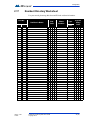
1
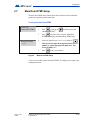
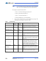
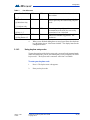
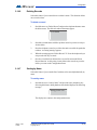
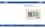
TX3 Series
TELEPHONE ACCESS SYSTEM
User Guide - Keypad Configuration
Version 1.00.1
LT-968
Mircom
Copyright 2010
1 (42)
Copyright 2010 Mircom Inc.
All rights reserved.
Mircom Administrator Guide v.1.00.0 for Windows 2000/NT/XP®.
This manual, as well as the software described in it, is provided under licence or other agreements
and may be used or copied only in accordance with the terms of such license. The content of this
manual is furnished for informational use only. It is subject to change without notice, and should not
be construed as a commitment by Mircom. Mircom assumes no responsibility or liability for any errors
or inaccuracies that appear in this book.
Except as permitted by such license, no part of this publication may be reproduced, stored in a
retrieval system, transmitted in any form by means electronic, mechanical, using any recorded
media, or any other format without the prior written permission of Mircom.
Microsoft, MS-DOS, Windows, and Windows 2000/NT/XP are either registered trademarks or
trademarks of Microsoft Corporation in the United States and/or other countries.
Mircom
25 Interchange Way
Vaughan, Ontario
L4K 5W3
905.660.4655
Fax:905.660.4113
2 (42)
LT-968
Version 1.00.1
Copyright 2010
Contents
1
Introduction 7
1.1
Introducing the TX3 Telephone Access System 8
1.2
Warranty and Special Notices 8
1.3
About This Manual 8
2
Configuration 11
2.1
Using the TX3 Telephone Access System 12
2.2
Frequently Used Functions 12
2.3
Viewing Configuration Information 13
2.4
Entering Configuration Mode 13
2.5
Keypad Navigation 14
2.6
Exiting Configuration Mode 14
2.7
Main Door DTMF Setup 15
2.8
Auxiliary Door DTMF setup 16
2.9
Setting the Talk and Door Timers 17
2.10
Talk Timer setup 17
2.11
Main Door Timer Setup 18
2.12
Auxiliary Door Timer Setup 19
2.13
Changing Your Passcode 19
2.14
Configuration Menu using the Entry Panel Keypad 20
2.15
Glossary 28
2.16
TX3 ADC Frequently Asked Questions 29
2.17
Resident Directory Worksheet 33
Warranty & Warning Information 35
Special Notices 38
3 (42)
LT-968
Telephone Access System User Guide
Copyright 2010
Version 1.00.1
4 (42)
LT-968
Telephone Access System User Guide
Copyright 2010
Version 1.00.1
List of Figures
Figure 1.
Viewing Configuration information 13
Figure 2.
Entering Configuration Mode 13
Figure 3.
Keypad Navigation 14
Figure 4.
Main Door DTMF Setup 15
Figure 5.
Auxiliary Door DTMF Setup 16
Figure 6.
Talk Timer Setup 17
Figure 7.
Main Door Timer setup 18
Figure 8.
Auxiliary Door Timer Setup 19
Figure 9.
Changing Your Passcode 20
Figure 10.
Entering Resident’s Names 21
Version 1.00.1
LT-968
Telephone Access System User Guide
Copyright 2010
5 (42)
6 (42)
LT-968
Telephone Access System User Guide
Copyright 2010
Version 1.00.1
1
Introduction
This manual provides information on the most common features of the TX3
Telephone Access System and provides you with instructions to configure the
TX3 Telephone Access System from the main entry panel keypad.
Note:
Mircom periodically updates panel firmware and Configurator
Software to add features and correct any minor inconsistencies.
For information about the latest firmware or software visit the
Mircom website at www.mircom.com.
This manual explains how to
Version 1.00.1
LT-968
•
Operate the TX3 Telephone Access Panel
•
View Configuration Info
•
Add, delete, and edit records
•
Set the Main and Auxiliary doors’ DTMF (the touch tone key to press to
open the doors)
•
Set the talk timer and door timers
•
Change your password
Telephone Access System User Guide
Copyright 2010
7 (42)
Introduction
1.1
Introducing the TX3 Telephone Access System
The TX3 Telephone Access System is part of the Mircom suite of products that
provide building ready monitoring, control and integrated security solutions for
use in the high end multi-tenant residential market.
The TX3 Telephone Access System addresses the need within today’s high end
multi-tenant residential market for an easy-to-use tenant access system and an
easy-to-use configuration utility. The TX3 Telephone Access System creates an
aesthetically pleasing high quality entry system for residents and their visitors in
a multi-unit dwelling establishment.
This manual provides the technician with information about the keypad
configuration of the TX3 Telephone Access System and explains how to
configure various components for a new system, including the modification of an
existing system.
1.2
Warranty and Special Notices
Mircom values your business and always attempts to provide you with the very
best service.
Please see the Warranty and Special Notices chapter on page 35 for information
about the warranty and special notices about equipment use.
1.3
About This Manual
This manual provides comprehensive information on the installation and
configuration of the Touch Screen by the installation technician. Tasks are
described in the order that they are likely to be performed.
1.3.1
Version Control
The version number appears on the front cover and changes whenever there is a
major or minor update to any part of the system regarding operation or
configuration.
The following convention indicates major or minor changes:
Initial release. Version 1.00.0
Major change. Version 2.00.0
Minor change. Version 2.01.0
Pre-release changes. Version 2.01.1
8 (42)
LT-968
Telephone Access System User Guide
Copyright 2010
Version 1.00.1
Introduction
1.3.2
Additional Documentation
For additional documentation, see the following Mircom literature:
1.3.3
•
TX3-CX Touch Screen Administrators Guide LT-995
•
TX3 Telephone/Card Access System Installation and Operation Manual
LT-969
•
TX3-CX Card Access System Installation and Operation Manual LT-980
•
TX3 Two Door Card Access System Kit Catalogue Number 6531
•
TX3 Series Elevator Restriction Accessories Catalogue Number 6532
Key Terms
The following terms are common and specific to Touch Screen:
CAU. Card Access Unit
ERU. Elevator Restriction Unit
LCU. Lobby Control Unit
1.3.4
Contact Us
You can contact us from Monday to Friday 8:00 A.M. to 5:00 P.M. E.S.T.
1.3.5
General Inquiries
Toll Free: 1-888-660-4655
Local: 905-660-4655
1.3.6
Customer Service
Toll Free: 1-888-MIRCOM5
Local: 905-695-3535
Version 1.00.1
LT-968
Telephone Access System User Guide
Copyright 2010
9 (42)
Introduction
Local Fax: 905-660-4113
Toll-Free Fax: 1-888-660-4113
1.3.7
Technical Support
For technical support contact Mircom’s Technical Support Department between
8 A.M. and 5 P.M. (EST) Monday through Friday, excluding holidays.
Toll Free: 1-888-MIRCOM5
Local: 905-695-3535
Local Phone: 905-660-4655
Toll Free Phone: 1-888-660-4655
Email: [email protected]
1.3.8
Website
www.mircom.com
1.3.9
Email
[email protected]
10 (42)
LT-968
Telephone Access System User Guide
Copyright 2010
Version 1.00.1
2
Configuration
This chapter provides information on how to configure the most commonly used
functions of the TX3 Telephone Access System.
This chapter explains
Version 1.00.1
LT-968
•
How to access the TX3 Telephone Access System
•
Frequently Used Functions
•
Viewing Configuration Information
•
Keypad Navigation
•
Entering Configuration Mode
•
Exiting Configuration Mode
•
Main Door DTMF Setup
•
Auxiliary (Aux) Door DTMF setup
•
Setting the Talk and Door Timers
•
Talk Timer setup
•
Main Door Timer setup
•
Auxiliary (Aux) Door Timer setup
•
Changing Your Passcode
•
Configuration Menu using the Entry Panel Keypad
•
Glossary
•
TX3 ADC Frequently Asked Questions
•
Resident Directory Worksheet
Telephone Access System User Guide
Copyright 2010
11 (42)
Configuration
2.1
Using the TX3 Telephone Access System
The TX3 Entry Panel LCD shows a scrollable view of the resident names and dial
codes. The LCD also comes in an 8 line LCD handset version and a paper version
of the resident list is available.
To use the TX3 Telephone Access System
1.
To view the resident list press the up or down arrow keys to scroll the list
line by line.
or
To view the resident list page by page use the star key to scroll page up and
number key to scroll page down.
2.2
2.
Key in the dial code associated with the resident you wish to speak to or
press the Telephone Key when the cursor is on the resident’s name. For the
handset version, first pick up the phone and then key in the dial code or
press the Telephone Key.
3.
Once the resident grants entry permission, the door unlocks. For the
handset version, hang up the phone and proceed through the door.
Frequently Used Functions
The following instructions are for the more commonly used features of the TX3
Telephone Access System.
Features include:
Version 1.00.1
LT-968
•
Entering and exiting configuration mode
•
Adding residents
•
Edit and delete functions
•
Timer settings
•
Changing the password.
Telephone Access System User Guide
Copyright 2010
12 (42)
Configuration
2.3
Viewing Configuration Information
To view configuration information, you must first enter the configuration mode.
To enter configuration mode
Main Menu
1.
Press
.
2.
Press the
1. Configuration
2. Operation
3. View CFG Info
Press the
3.
Figure 1.
2.4
(scroll down) to “View Cfg Info”.
key to enter.
The configuration information displays. You may
need to scroll to view all the information.
Viewing Configuration information
Entering Configuration Mode
To make changes to the resident list at the panel, you must first enter the
configuration mode.
To enter configuration mode
Enter the Passcode
[_________]
1.
Press
.
2.
Select Configuration menu.
3.
Enter the passcode.
4.
If you have not set a personal password,
press
(four-digit factory default).
5.
If you have set a personal passcode, enter your
passcode.
You are now in configuration mode.
Figure 2.
Version 1.00.1
LT-968
Entering Configuration Mode
Telephone Access System User Guide
Copyright 2010
13 (42)
Configuration
2.5
Keypad Navigation
The diagram below shows how to use the keypad when in CONFIGURATION
MODE.
In configuration
mode
Press
to scroll up
Press
down.
to scroll
In configuration
mode
Press
left.
*
Press
to enter
and confirm selection.
to move
Press
to cancel
the selection or exit
Press # to move right for checking and un-checking
the check box
Figure 3.
2.6
Keypad Navigation
Exiting Configuration Mode
Configuration Menu
1. System Option
To exit configuration mode
1.
14 (42)
LT-968
Press
info key to “Exit”.
Telephone Access System User Guide
Copyright 2010
Version 1.00.1
Configuration
2.7
Main Door DTMF Setup
The main door DTMF setup feature allows the resident to use their telephone
touch tone keypad to open the main door.
To set up the main door DTMF
2.Line Type
3.Main Door DTMF<
Main Door DTMF
[ x ] ‘9’
1.
Select Configuration Menu, System Option.
2.
Press
(scroll up) or
“Main Door DTMF”.
3.
Press
when the arrow is beside “Main Door
DTMF”, the display enters Main Door DTMF setup.
4.
Select any digit between 1 to 9, * or #, and press
.
This selection becomes the designated (touch tone)
number or symbol that opens the main door. The
factory default is “9”.
5.
Figure 4.
(scroll down) to find
Press
to save and continue.
Main Door DTMF Setup
You have successfully set the main door DTMF. The display now returns to the
configuration menu.
Version 1.00.1
LT-968
Telephone Access System User Guide
Copyright 2010
15 (42)
Configuration
2.8
Auxiliary Door DTMF setup
The auxiliary door DTMF setup feature allows the resident to use their telephone
touch tone keypad to open the auxiliary door.
To set up the auxiliary door DTMF
If you have not setup Main Door DTMF,
3. Main Door DTMF
4. Aux Door DTMF<
1.
Press
(scroll up) or
(scroll down) to
find “Aux Door DTMF”.
Aux Door DTMF
[x]6
2.
Press
when the arrow is beside “Aux Door
DTMF”. The display enters Aux Door DTMF setup.
3.
Select any digit between 1 to 9, * or #, and press
.
This selection becomes the designated (touch tone)
number or symbol that opens the auxiliary door. The
factory default is “6”.
DO NOT select “4”, this is used to refuse entry or
disconnect.
4.
Figure 5.
Press
to save and continue.
Auxiliary Door DTMF Setup
You have successfully set the auxiliary door DTMF. The display now returns to
the configuration menu.
16 (42)
LT-968
Telephone Access System User Guide
Copyright 2010
Version 1.00.1
Configuration
2.9
Setting the Talk and Door Timers
To set the talk time and door timers, you must be in Configuration Mode. Refer
to Entering Configuration Mode on page 13 for instructions.
2.10
Talk Timer setup
The talk timer defines the maximum length of time that a visitor speaks with a
resident.
To set up the talk timer
6. Aux door Timer
7. Talk Timer
Talk Timer
[ 060 ]
Figure 6.
1.
Select Configuration Menu, System Option.
2.
Press
(scroll up) or
find “Talk Timer”.
3.
Press
when the arrow is beside “Talk
Timer”. The display enters Talk Timer setup.
4.
Enter time duration between 10 to 300 seconds.
The factory default is 60 seconds.
5.
Use the up down arrows to change value.
6.
Press
(scroll down) to
to save and continue.
Talk Timer Setup
You have successfully set up the on-line timer. The display now returns to the
configuration menu.
Version 1.00.1
LT-968
Telephone Access System User Guide
Copyright 2010
17 (42)
Configuration
2.11
Main Door Timer Setup
The main door timer defines the length of time the main (lobby) door release stays
unlocked.
To set up the main door
4. Aux Door DTMF
5. Main Door Timer <
Main Door Timer
[ 010 ]
1.
Press
(scroll up) or
(scroll down) to
find “Door Timer”.
2.
Press
when the arrow is beside “Main Door
Timer”. You enter Door Timer setup.
3.
Use the arrow keys to find a time duration between
1 and 60 seconds. Press
to select.
The factory default is 30 seconds.
4.
Figure 7.
Press
to save and continue.
Main Door Timer setup
You have successfully set up the main door timer. The display now returns to the
configuration menu.
18 (42)
LT-968
Telephone Access System User Guide
Copyright 2010
Version 1.00.1
Configuration
2.12
Auxiliary Door Timer Setup
The auxiliary door timer defines the length of time the auxiliary door stays
unlocked.
To set up the auxiliary door
5. Main Door Timer
6. Aux Door Timer <
Aux Door Timer
[ 010 ]
1.
Press
(scroll up) or
(scroll down) to
find “Door Timer”.
2.
Press
when the arrow is beside “Aux Door
Timer”. You enter Aux Door Timer setup.
3.
Use the arrow keys to find a time duration between
1 and 60 seconds. Press
to select.
The factory default is 30 seconds.
4.
Figure 8.
Press
to save and continue.
Auxiliary Door Timer Setup
You have successfully set up the auxiliary door timer. The display now returns to
the configuration menu.
2.13
Changing Your Passcode
To change your passcode, you must be in configuration Mode. Refer to
Entering configuration Mode on page 13 for instructions.
Note:
Version 1.00.1
LT-968
The default passcode for level 3 is 3333. The default passcode for
level 2 is 2222. Passcode level 1 is not used.
Telephone Access System User Guide
Copyright 2010
19 (42)
Configuration
To change your passcode
7. Correlation
8. Change Passcode <
1.
Press
(scroll up) or
(scroll down) to
find “Change Passcode”.
2.
Press
when the arrow is beside “Change
Passcode”. The display enters Change Passcode
setup.
3.
Use the up down arrows to see all of the access
levels.
Enter Access Level
< 001>
4.
Press
Enter New Passcode
[ 3333 ]
5.
Enter your new password for the access level you
have chosen. It must consist of at least four digits
up to a maximum of 99999999.
Re-enter Passcode
[ 3333 ]
6.
You will be asked to re-enter new passcode.
7.
Press
Figure 9.
to select and continue.
to save and continue.
Changing Your Passcode
You have successfully changed your passcode for one access level. The display
now returns to the configuration menu.
2.14
Configuration Menu using the Entry Panel Keypad
The Configuration Menu contains the database menu. The Database Menu lets
you add, edit and delete resident records, and consists of the following options:
Version 1.00.1
LT-968
•
Add Record
•
Edit Record
•
Delete Record
•
Sort by name
•
Sort by d-code (sort by dial code)
•
Auto program
•
Delete all record
Telephone Access System User Guide
Copyright 2010
20 (42)
Configuration
2.14.1
Adding New Records
Photocopy and then fill out the worksheet provided on page 33 to record the
resident information needed for adding new records.
2.14.2
Entering resident names
Once you have entered the configuration menu, select the database menu and
then press the telephone key to enter the Add Record menu. After Apt no and
Dial code, the following screen appears:
Enter Resident Name
[__________]
To enter a resident name
1.
Use the number keys to select the appropriate character. See Figure 10 for
the characters that correspond to each number.
2.
Press any number key once, twice, three or more times to cycle through the
characters associated with that key. When you reach the character you
want, stop pressing the key and the character will remain in the display.
press once = comma
press twice = dash
press 3 times = left bracket
press 4 times = right bracket
press 5 times = /
press 6 times = &
press 7 times = 1
press * once = backspace
press 0 once to delete a character
press 0 twice = 0
press # once = space
Figure 10.
Version 1.00.1
LT-968
Entering Resident’s Names
Telephone Access System User Guide
Copyright 2010
21 (42)
Configuration
Note:
If you accidentally enter the wrong character while configuring a
name, press * once to backspace or press 0 to delete the letter.
For example, to enter the last name “Doe”,
a. Press “3” four times for the upper case letter “D”.
b. Press “6” three times for the letter “o”.
c. Press “3” two times for the letter “e”.
d. Press the telephone key to save and continue.
3.
Table 1:
Once you have entered the name, press the telephone key to accept. The
following screens will appear as shown in Table 1.
List of Screens
Database Menu
Enter Resident Name
NSL
System
YES
ADC
System
YES
Enter Apt No
YES
YES
[_ _ _ _]
Enter Dial Code
YES
YES
Enter the resident’s dial code (up to 4 digits).
____
Enter Keyless Code
YES
YES
[_ _ _ _]
Enter Relay Code
YES
N/A
Enter the assigned keyless code, up to 6 digits
(if used). See below for using keyless entry
codes.
Enter the resident’s assigned relay code.
[_ _ _ _]
Enter Telephone #
N/A
YES
YES
YES
YES
YES
[____________]
Hide Res Name
[x] Display
Enter Elev Rest Addr
Explanation/Description
Enter the resident’s name. The name must be
unique and a maximum of 15 characters.
Enter the resident’s apartment number (up to 4
digits).
Note: Relay codes start at 1 for the first relay,
up to 1535.
Enter the resident’s telephone number (up to
18 digits including a comma that is used as 1
second delay). Use the up arrow key for a
comma and the down arrow key for a dash
which is optional. Press the Enter (telephone
key) to accept the telephone number.
This feature turns the resident information
display ON or OFF. When OFF the resident’s
information is only displayed in configuration
mode.
Enter the ID (or address) of the Elevator
Restriction controller for the resident.
[_ _]
22 (42)
LT-968
Telephone Access System User Guide
Copyright 2010
Version 1.00.1
Configuration
Table 1:
List of Screens
Enter Elev Rest Relay
YES
YES
Enter the elevator restriction relay number for
the resident.
[_ _]
Keyless Corr
YES
YES
Select which door (main, auxiliary or both)
can be opened by the resident using a keyless
code.
[ ] Aux door relay
Line to Use
YES
YES
[x] Line 1 - 5
Enter Ring Pattern
YES
N/A
Enter the speech path for resident to
communicate to the ADC line or to a relay
control unit. Line 1 is default.
Enter the ring pattern for the resident. See
Table 2 for available ring patterns. The
default is 1.
[x] Main door relay
[x] Ring Pattern 1-5
4.
2.14.3
When you are finished adding the new record, press Enter (the telephone
key) the display shows “New Record Added”. The display returns to the
configuration menu.
Using keyless entry codes
To enter the premises with a keyless entry code, you must first be in normal mode.
While in normal mode, press 0, after which point you are prompted with “Enter
keyless code”. The keyless code is a numeric value from 1 to 999999.
To enter your keyless code
Version 1.00.1
LT-968
1.
Press 0. The keyless enter code appears.
2.
Enter your keyless code.
Telephone Access System User Guide
Copyright 2010
23 (42)
Configuration
2.14.4
Selecting a ring pattern (NSL System only)
The ring pattern selection is part of the Database Menu.
Table 2:
Available Ring Pattern
Ring
Pattern
1
Available Ring Pattern
2s ON
4s OFF
standard
ring A
2
800ms
ON
400ms
OFF
800ms
ON
4s OFF
distinct
ring B
3
200ms
ON
400ms
OFF
200ms
ON
400ms
OFF
800ms
ON
4s OFF
distinct
ring C
4
200ms
ON
400ms
OFF
800ms
ON
400ms
OFF
200ms
ON
4s OFF
distinct
ring D
5
2.14.5
One single ringing burst
Editing Records
To edit a record
1.
Select “Edit Record” and use the up/down key to scroll through the
residents.
2.
Press the telephone button to select the resident’s name for editing.
1212>Smith
1213 Jones
1214 Hath
1215 Johnson
24 (42)
LT-968
3.
Use the down arrow key to scroll down the list of fields, such as Apartment
number, Resident name, Dial code Keyless code, relay code, telephone
number, etc.
4.
Once the arrow is pointing to the field that requires a change, press the
telephone key to edit.
5.
Re-enter the correct information. See paragraph 2.14.2 for instructions on
entering data.
6.
When you are finished editing the record, press the info key. The display
returns to the record list. At this point you may edit another record or press
the information key to return to the record list.
Telephone Access System User Guide
Copyright 2010
Version 1.00.1
Configuration
2.14.6
Deleting Records
Select this feature if you want to delete a resident’s name. This function deletes
one record at a time.
To delete a record
1.
Scroll the arrow to “Delete Record” and press the telephone button to enter
the delete menu. The dial code and resident name appear:
1212>Smith
2.14.7
2.
Scroll the resident names with the up/down arrow keys to the record you
wish to delete.
3.
Press the telephone (enter) key to delete the entire record for the particular
resident. A warning message appears.
4.
When the warning appears “Delete Record? Y. Press the telephone key to
accept or the info key to cancel.
5.
Once the record has been deleted, the screen will return to the Delete
Record function. At this point you may delete other records or press the
info key to return to the Configuration menu.
Sorting by Name
Select this feature if you want the list of residents to be sorted alphabetically by
name.
To sort by name
1.
Scroll the arrow to “Sort by Name” and press the enter (telephone) key.
Selecting this feature during database downloaded displays the following
message:
Sorting please wait
The display now returns to the configuration menu.
Version 1.00.1
LT-968
Telephone Access System User Guide
Copyright 2010
25 (42)
Configuration
2.14.8
Sorting by d-code
To sort by d-code
Select this feature if you want the list of residents to be sorted numerically by dial
code. Scroll the arrow to “Sort by d-code” and press enter (telephone) key. The
following message appears:
Sorting please wait
The display now returns to the database menu.
2.14.9
Auto configuration
This selection allows you to add a group of residents from a minimum of 10 to a
maximum of 200 names.
To chose the auto program
1.
Scroll the arrow to “Auto Program” in the main Configuration menu and
press the enter (telephone) key to select. The display will now show the
following message:
Number of Records
< 010>
2.
Use the up arrow to move from number of residents in increments of 5 to
the desired number. The maximum depends on the TX3 Model (it can be
200, 1000 or 2000).
Note:
3.
Only 200 names can be added at a time.
Press the telephone (enter) key to accept. The next screen will ask for
resident name. Enter one of the resident names using the alphanumeric
keypad.
Enter Resident
Name
4.
Press the telephone (enter) key to accept. The next screen will ask for the
resident’s dial code. All the rest of the dial codes increase by one.
Start Dial Code
26 (42)
LT-968
Telephone Access System User Guide
Copyright 2010
Version 1.00.1
Configuration
5.
Use the number keypad to enter the start dial code. The next screen asks
for the resident’s keyless code. All the rest of the keyless code increase by
one.
Start Keyless Code
6.
Use the number keypad to enter the start keyless code. The next screen
asks which audio line to use.
Line Number to use
7.
Use the up arrow to enter the line number. Press the enter (telephone) key
to enter.
8.
Use the up arrow to enter the line number. Press the enter (telephone) key
to enter. The next screen asks for the relay code.
Relay Code
9.
2.14.10
Press info key to return to previous menu. View the residents entered by
scrolling page up and down using the * and # keys. To enter the proper
resident names, use the edit feature.
Deleting All Records
Select this feature if you want to delete all the resident data (all names, dial codes,
everything).
To delete all the resident data
1.
Scroll the arrow to “Delete all Records” and press the enter (telephone)
key. The following message appears:
Delete all records?
2.
Version 1.00.1
LT-968
Press the enter (telephone) key to accept or the info key to cancel. The
display now returns to the database menu.
Telephone Access System User Guide
Copyright 2010
27 (42)
Configuration
2.15
Glossary
Add Record
This function is used to add a new resident to the system. Part of the Database
Menu.
Aux Door
When this function is set, the resident can press a number on his or her telephone
pad to unlock the auxiliary door.
Delete Record
This function is used to delete the an entire resident record from the system.
Part of the Database Menu.
Dial Code
A one- to four-digit code that a visitor enters into the lobby unit to call a resident.
DTMF
“Dual Tone Modulated Frequency” is a technical term for “touch tone”.
Edit Record
This function is used to change a resident’s existing record.
Keyless Code
This feature allows you to enter a 1 to 6 digit code to let residents to open the
main door without a key.
Keypad
Navigation
Instructions on how to use the keypad.
Talk Timer
This operation controls the maximum length of time that a visitor can speak
with a resident at the entry panel.
configuration
Mode
This operation consists of multiple functions that allow you to customize your
Telephone Access System.
Potentiometer
A technical term for a variable resistor which functions as a contrast control.
Scrolling
Directory
An electronic directory that lists the residents of the building, line by line or
page by page.
28 (42)
LT-968
Telephone Access System User Guide
Copyright 2010
Version 1.00.1
Configuration
2.16
TX3 ADC Frequently Asked Questions
Q. What is the ADC feature?
A. The telephone access system is an auto-dialer that is connected to a public
telephone line. When a visitor enters a resident’s dial code number, the system
dials the resident’s home or cell telephone number (Note: as a security
precaution, the visitor cannot see the resident’s home or cell telephone number).
When the resident answers the call, he or she can press “9” (or whatever number
is selected as the Main Door DTMF) to unlock the main door and automatically
end the telephone call.
Q. Visitors cannot place calls to residents. Why?
A. If the problem is consistent with every resident, there may be a problem with
the telephone line. Check the telephone line with a regular telephone for a dial
tone. If the dial tone is not present contact your local telephone company. If the
problem is consistent for one resident only, the resident’s telephone number may
be programmed incorrectly. Check the configuration to confirm that the
resident’s telephone number and area code are entered correctly.
Q. Why does the system hang up as soon as a visitor begins to talk with a
resident?
A. The talk timer may be set for too short a duration. While in configuration
mode, check that the talk timer is set to more than 30 seconds (factory default is
60 seconds).
Q. Why can’t residents unlock the door/gate from their units by pressing
“9” on their telephones?
A. This may be caused by one of the following:
Incorrect Main Door DTMF setup.
Solution: While in configuration mode, check that the “Main Door” (DTMF) is
programmed to digit “9”.
Improper voltage on the door strike power supply.
Solution: Check for the correct voltage on the door strike power supply.
The door strike and system (main board) wires may be damaged or loose.
Solution: Check and verify that the door strike and system wires are intact.
Q. When a visitor places a call and begins to talk, he or she cannot hear the
resident. Why?
A. The speaker may not be working correctly. Unlock the entry panel and
perform a visual inspection of the speaker:
Look for loose wires as well as damaged components.
Version 1.00.1
LT-968
Telephone Access System User Guide
Copyright 2010
29 (42)
Configuration
Check that the volume in the panel speaker is set properly, by entering the
configuration mode and reviewing the speaker volume setting.
If there are no loose wires and the volume in the panel speaker is set properly, then
adjust the potentiometer marked “SPEAKER” located on the back of the front
entry panel display (must open the front entry panel door).
Q. The LCD display has no display or the display has dark blocks on it.
Why?
A. There may be a problem with the contrast level. The potentiometer (contrast
control) is located on the back of the keypad/display board. Unlock the front door
and adjust the potentiometer for a darker or light contrast display.
Q. I misplaced the key for the telephone access system. How do I obtain a
replacement?
A. The Mircom key part number is LK-304. Contact your local distributor or
Mircom Head Office for a replacement.
Q. What happens when the visitor gets an answering machine when trying
to contact a resident?
A. The system will allow the visitor to leave a voice message on the answering
machine.
TX3 NSL Frequently Asked Questions
Q. What is the NSL feature?
A. The NSL (No Subscriber Line) operation does not use a dedicated public
subscribed telephone line; rather the TX3-NSL-8M NSL Units (and TX3-8EC,
TX3-16EC NSL Expanders) in your electrical/telephone room intercept all
resident telephone lines coming into the building and communicate directly to
them.
Q. Why can’t residents unlock the door/gate by pressing the digit “9”on
their telephones?
A. This may be caused by one of the following:
Incorrect Main Door DTMF setup.
Solution: While in configuration mode, check that the “Main Door” (DTMF) is
programmed to digit “9”.
Improper voltage on the door strike power supply.
Solution: Check for the correct voltage on the door strike power supply.
The door strike and system (main board) wires may be damaged or loose.
Solution: Check and verify that the door strike and system wires are intact.
30 (42)
LT-968
Telephone Access System User Guide
Copyright 2010
Version 1.00.1
Configuration
Q. Why does the system hang up as soon as a visitor begins to communicate
with a resident?
A. This may be caused by the following: the talk timer may be set for too short a
duration. While in configuration mode, check that the talk timer is set to more
than 30 seconds (factory default is set to 60 seconds).
Q. When a visitor places a call and begins to talk, he or she cannot hear the
resident. Why?
A. The speaker may not be working correctly. Unlock the panel and perform a
visual inspection of the speaker:
Look for loose wires or loose solders as well as damaged components.
Check that the volume in the panel speaker is set properly, by entering the
configuration mode and review the speaker volume setting.
If there are no loose wires and the volume in the panel speaker is set properly,
there may be a problem with the speaker, then adjust the potentiometer marked
“SPEAKER” located on the back of the front entry panel display (must open the
front entry panel door).
Q. The LCD display has no display or the display has dark blocks on it.
Why?
A. There may be a problem with the contrast level. The potentiometer (contrast
control) is located on the back of the keypad/display board. Unlock the front door
and adjust the potentiometer for a darker or light contrast display.
Q. Why is there no dial tone when a visitor calls a resident?
A. The NSL system does not utilize an independent telephone line, and therefore
does not require a dial tone. The system works with the TX3-NSL-8M Relay unit
to ring/call your apartment.
Q. I misplaced the key for the telephone access system. How do I obtain a
replacement?
A. The Mircom key part number is LK-304. Contact your local distributor or
Mircom Head Office for a replacement.
Q. What happens when the visitor gets an answering machine when trying
to contact a resident?
A. The system will allow the visitor to leave a voice message on the answering
machine.
Version 1.00.1
LT-968
Telephone Access System User Guide
Copyright 2010
31 (42)
Configuration
Q. Is the ring pattern programmable?
The ring pattern selection is a standard NSL system feature.The system provides
up to five ring patterns to choose from for every resident.
32 (42)
LT-968
Telephone Access System User Guide
Copyright 2010
Version 1.00.1
Configuration
2.17
Resident Directory Worksheet
For your records, photocopy this sheet and fill in the resident information.
Unit No.
Resident’s Name
Flr.
Version 1.00.1
LT-968
Apt.
Dial
Code
Telephone Access System User Guide
Copyright 2010
Phone
Number
Phone
Type
(pulse or
tone)
Keyless
Entry
Code
33 (42)
Configuration
34 (42)
LT-968
Telephone Access System User Guide
Copyright 2010
Version 1.00.1
Warranty & Warning Information
Limited Warranty
Mircom Technologies Ltd. together with its subsidiaries and affiliates
(collectively, the “Mircom Group of Companies”) warrants the original
purchaser that for a period of two years from the date of manufacture, the product
shall be free of defects in materials and workmanship under normal use. During
the warranty period, Mircom shall, at its option, repair or replace any defective
product upon return of the product to its factory, at no charge for labour and
materials. Any replacement and/or repaired parts are warranted for the
remainder of the original warranty or ninety (90) days, whichever is longer. The
original owner must promptly notify Mircom in writing that there is defect in
material or workmanship, such written notice to be received in all events prior to
expiration of the warranty period.
International Warranty
The warranty for international customers is the same as for any customer within
Canada and the United States, with the exception that Mircom shall not be
responsible for any customs fees, taxes, or VAT that may be due.
Conditions to Void Warranty
This warranty applies only to defects in parts and workmanship relating to
normal use. It does not cover:
Version 1.00.1
LT-968
•
damage incurred in shipping or handling;
•
damage caused by disaster such as fire, flood, wind, earthquake or
lightning;
•
damage due to causes beyond the control of Mircom such as excessive
voltage, mechanical shock or
•
water damage;
•
damage caused by unauthorized attachment, alterations, modifications or
foreign objects;
Telephone Access System User Guide
Copyright 2010
35 (42)
•
damage caused by peripherals (unless such peripherals were supplied by
Mircom);
•
defects caused by failure to provide a suitable installation environment for
the products;
•
damage caused by use of the products for purposes other than those for
which it was designed;
•
damage from improper maintenance;
•
damage arising out of any other abuse, mishandling or improper
application of the products.
Warranty Procedure
To obtain service under this warranty, please return the item(s) in question to the
point of purchase. All authorized distributors and dealers have a warranty
program. Anyone returning goods to Mircom must first obtain an authorization
number. Mircom will not accept any shipment whatsoever for which prior
authorization has not been obtained.
Note:
Unless specific pre-authorization in writing is obtained from
Mircom management, no credits will be issued for custom
fabricated products or parts or for complete fire alarm system.
Mircom will at its sole option, repair or replace parts under
warranty. Advance replacements for such items must be purchased.
Note:
Mircom’s liability for failure to repair the product under this
warranty after a reasonable number of attempts will be limited to a
replacement of the product, as the exclusive remedy for breach of
warranty.
Disclaimer of Warranties
This warranty contains the entire warranty and shall be in lieu of any and all other
warranties, whether expressed or implied (including all implied warranties of
merchantability or fitness for a particular purpose) And of all other obligations or
liabilities on the part of Mircom neither assumes nor authorizes any other person
purporting to act on its behalf to modify or to change this warranty, nor to assume
for it any other warranty or liability concerning this product.
This disclaimer of warranties and limited warranty are governed by the laws of
the province of Ontario, Canada.
36 (42)
LT-968
Telephone Access System User Guide
Copyright 2010
Version 1.00.1
Out of Warranty Repairs
Mircom will at its option repair or replace out-of-warranty products which are
returned to its factory according to the following conditions. Anyone returning
goods to Mircom must first obtain an authorization number. Mircom will not
accept any shipment whatsoever for which prior authorization has not been
obtained.
Products which Mircom determines to be repairable will be repaired and
returned. A set fee which Mircom has predetermined and which may be revised
from time to time, will be charged for each unit repaired.
Products which Mircom determines not to be repairable will be replaced by the
nearest equivalent product available at that time. The current market price of the
replacement product will be charged for each replacement unit.
WARNING
Mircom recommends that the entire system be completely tested on a regular
basis. However, despite frequent testing, and due to, but not limited to, criminal
tampering or electrical disruption, it is possible for this product to fail to perform
as expected.
NOTE
Under no circumstances shall Mircom be liable for any special, incidental, or
consequential damages based upon breach of warranty, breach of contract,
negligence, strict liability, or any other legal theory. Such damages include, but
are not limited to, loss of profits, loss of the product or any associated equipment,
cost of capital, cost of substitute or replacement equipment, facilities or services,
down time, purchaser’s time, the claims of third parties, including customers, and
injury to property.
MIRCOM MAKES NO WARRANTY OF MERCHANTABILITY OR
FITNESS FOR A PARTICULAR PURPOSE WITH RESPECT TO ITS
GOODS DELIVERED, NOR IS THERE ANY OTHER WARRANTY,
EXPRESSED OR IMPLIED, EXCEPT FOR THE WARRANTY
CONTAINED HEREIN.
Version 1.00.1
LT-968
Telephone Access System User Guide
Copyright 2010
37 (42)
Special Notices
Product Model Number: TX3
AC REN (U.S.): 0.0B
AC REN (CANADA): 0.0
Complies With
Federal Communications Commission (FCC):
•
TIA-968-A Technical requirement for connection of equipment tot he
telephone network.
•
CFR 47, Part 15, Subpart B, Class B
•
Unintentional Radiators
Industry Canada (IC):
•
Terminal attachment programme
•
CS-03, Issue 8 - Certification Specifications
•
ICES-003, ISSUE 4, CLASS B
•
Verification Authorization - Digital Apparatus
Registration Numbers
FCC (U.S.): 1M8OT00BTX3
IC (Canada): 1156A-TX3
Industry Canada Notice for all TX3 Products Sold in Canada
The Industry Canada label identifies certified equipment. This certification
means that the equipment meets certain telecommunications network protective,
operational, and safety requirements. Industry Canada does not guarantee the
equipment will operate to the user's satisfaction. Before installing this
equipment, users should ensure that it is permissible to be connected to the
facilities of the local telecommunication company. The equipment must also be
installed using an acceptable method of connection. The customer should be
aware that compliance with the above conditions may not prevent degradations
of service in some situations.
38 (42)
LT-968
Telephone Access System User Guide
Copyright 2010
Version 1.00.1
Repairs to certified equipment should be made by an authorized Canadian
maintenance facility designated by the supplier. Any repairs or alteration made
by the user to this equipment, or equipment malfunctions, may give the
telecommunications company cause to request the user to disconnect the
equipment. Users should ensure for their own protection that the earth ground
connections of the power utility, telephone lines and internal metallic water pipe
system, if present, are connected together. This is necessary both for proper
operation and for protection.
Caution:
Users should not attempt to make such connections themselves, but
should contact the appropriate electric inspection authority, or
electrician, as appropriate.
Note:
The Ringer Equivalence Number (REN) assigned to each terminal
device provides an indication of the maximum number of terminals
allowed to be connected to a telephone interface. The termination
on an interface may consist of any combination of devices subject
only to the requirement that the sum of the RENs of all the devices
does not exceed five.
FCC Notice for all TX3 Products Sold in the U.S.A.
Type of Service
The TX3 is designed to be used on standard device telephone lines. It connects to
the telephone line by means of a standard jack called the USOC RJ-11C (or
USOC FJ45S). Connection to telephone company-provided coin service (central
office implemented systems) is prohibited. Connection to party lines service is
subject to state tariffs.
Telephone Company Procedures
The goal of the telephone company is to provide you with the best service it can.
In order to do this, it may occasionally be necessary for them to make changes in
their equipment, operations or procedures. If these changes might affect your
service or the operation of your equipment, the telephone company will give you
notice, in writing, to allow you to make any changes necessary to maintain
uninterrupted service.
In certain circumstances, it may be necessary for the telephone company to
request information from you concerning the equipment which you have
connected to your telephone line. Upon request of the telephone company,
provide the FCC registration number and the ringer equivalence number (REN);
both of these items are listed on the equipment label. The sum of all of the RENs
Version 1.00.1
LT-968
Telephone Access System User Guide
Copyright 2010
39 (42)
on your telephone lines should be less than five in order to assure proper service
from the telephone company. In some cases, a sum of five may not be useable on
a given line.
Changes to Telephone Service
The telephone company may make changes in its facilities, equipment,
operations or procedures that could affect the operation of the equipment. If this
happens the telephone company will provide advance notice in order for you to
make necessary modifications to maintain uninterrupted service.
Ringer Equivalence Number
The REN is used to determine the number of devices that may be connected to a
telephone line. Excessive RENs on a telephone line may result in the devices not
ringing in response to an incoming call. In most but not all areas, the sum of
RENs should not exceed five (5.0). To be certain of the number of devices that
may be connected to a line, as determined by the total RENs, contact the local
telephone company. For products approved after July 23, 2001, the REN for this
product is Customer Information 3 July 2003 part of the product identifier that
has the format US:AAAEQ##TXXXX. The digits represented by ## are the
REN without a decimal point (e.g., 03 is a REN of 0.3). For earlier products, the
REN is separately shown on the label.
If Problems Arise
If any of your telephone equipment is not operating properly, you should
immediately remove it from your telephone line, as it may cause harm to the
telephone network. If the telephone company notes a problem, they may
temporarily discontinue service. When practical, they will notify you in advance
of this disconnection. If advance notice is not feasible, you will be notified as
soon as possible. When you are notified, you will be given the opportunity to
correct the problem and informed of your right to file a complaint with the FCC.
Contact your telephone company if you have any questions about your telephone
line. In the event repairs are ever needed on the Communicator, they should be
performed by Mircom or an authorized representative of Mircom. For
information contact Mircom at the address and telephone numbers in Chapter 1.
If this equipment, TX3 Telephone Access System, causes harm to the telephone
network, the telephone company will notify you in advance that temporary
discontinuance of service may be required. But if advance notice isn't practical,
the telephone company will notify the customer as soon as possible. Also, you
will be advised of your right to file a complaint with the FCC if you believe it is
necessary.
40 (42)
LT-968
Telephone Access System User Guide
Copyright 2010
Version 1.00.1
Product Identifier
This equipment complies with Part 68 of the FCC rules and the requirements
adopted by the ACTA. On the back of the front panel cover of this equipment is
a label that contains, among other information, a product identifier in the format
US:AAAEQ##TXXXX. If requested, this number must be provided to the
telephone company.
Telephone Connection
A plug and jack used to connect this equipment to the premises wiring and
telephone network must comply with the applicable FCC Part 68 rules and
requirements adopted by the ACTA. You are responsible for installing a
compliant telephone cord and modular plug into this product as described in this
manual. It is designed to be connected to a compatible modular jack that is also
compliant. See installation instructions for details.
Equipment Failure
If trouble is experienced with the TX3 Telephone Access System, for repair or
warranty information, please contact Mircom. If the equipment is causing harm
to the telephone network, the telephone company may request that you
disconnect the equipment until the problem is resolved.
Use on Party Lines
Connection to party line service is subject to state tariffs. Contact the state public
utility commission, public service commission or corporation commission for
information.
Use With Alarm Auto Dialers
If your institution has specially wired alarm equipment connected to the
telephone line, ensure the installation of the TX3 Telephone Access System does
not disable your alarm equipment. If you have questions about what will disable
alarm equipment, consult your telephone company or a qualified installer.
Version 1.00.1
LT-968
Telephone Access System User Guide
Copyright 2010
41 (42)
42 (42)
LT-968
Telephone Access System User Guide
Copyright 2010
Version 1.00.1