1
[
Editorial
by Rod Waller
]
Can you troubleshoot a Rain Bird RCSeries Controller? How skilled are you at
repair? We devoted this issue of the
Technical Newsletter to electromechanical controllers to challenge and inform
you. Plus, if you are a Rain Bird
Authorized Service Center (ASC), Level 2
or higher, you are asked to repair these
units to maintain your ASC status.
As a reminder, here is an excerpt from
the 1999 ASC Program Guide:
• Level 2 - “Perform repairs on-site or
within your inter-branch system on
75% of all electromechanical controllers.”
• Levels 3 & 4 – “Perform repairs on-site
or within your inter-branch system,
rather than sending them to outside
vendors, on 90% of all electromechanical and solid-state controllers.”
If you are having trouble meeting these
requirements, please let us know how
we can help. Your success is important
to Rain Bird.
An RC-Series Controller can be tested
in five minutes at the counter. Fifty
percent of the problems can be caught
right there. For example, if the controller tests OK, the trouble may be in
the field wiring or primary power supply. Identifying this quickly saves the
contractor time in the field. Testing
may yield some important clues,
enabling a more rapid field diagnosis.
By the way, Rain Bird receives numerous inquiries regarding Year 2000 compliance for RC-Series controllers. I’m
not kidding. Call it a hunch, but I think
they’ll work just fine.
Rod Waller
Authorized Service Center Manager
520.434.6259
[email protected]
Rain Bird Sales, Inc. • 6640 South
Bonney Ave. • Tucson, AZ 85706
continued from front
power off to the valves. The controller
will run as programmed, but no watering will occur.
• Check for the correct time/day. The
controller should always show the
correct time and day as long as it is connected to the primary power source. If
the time or day is not correct, check the
primary power, transformer, circuit
breaker or fuse.
• Check the primary power. Verify that 117
volt VAC power is on and correctly connected. If power is above 129 or below
105, contact a certified electrician.
• Check the transformer. The output
should be between 24 and 28 VAC. If not,
replace it.
• Check the circuit breaker or fuse.
If it is blown, it’s most
likely caused by
a field wiring
short. The
electromechani-
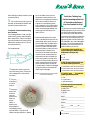
Timing Motor
(above)
Resistor
(below)
one problem.
• Check the clock motor (or timing motor).
The clock motor must operate continuously whether the controller is on or off,
in order to keep proper time; therefore,
this motor may fail after an extended
time. Verify that the motor is receiving
proper voltage. Then set the hour to the
correct time and wait one hour. If the
hour dial has not moved, replace the
motor.
• Change the resistor. Each RC Controller
has a 43 ohm, 5-watt resistor, wired inseries to the timing motor. The purpose
of this resistor is to limit current and
reduce heat in the timing motor.
Without it, the motor will not last long.
When changing the timing motor,
you must change the resistor also.
(Part #651137)
• Test the gears and clutches. The RC-Series
electromechanical controllers all use
gears to transfer the rotation of the clock
motor to the hour and station timing. If
you suspect a problem, try to very gently
rotate the station dial and hour dial on
the face plate in the opposite direction
from the direction that the arrows show.
If it rotates backwards without much
force, the gear and clutch assembly is
stripped and it’s time to replace it.
DO NOT EXERT EXCESSIVE FORCE
FOR THIS TEST.
cal controller will stop on the station
that caused the problem. Reset the controller in rest position, replace the fuse
or circuit breaker. Manually advance to
station #1 and allow it to run for one
minute. If it operates correctly, continue
to Station #2 and the other stations,
repeating the process until the fuse
blows. Disconnect the wire that operates
that valve. Be sure to test all stations
because there could be more than
• Check the advance motor (or rapid
advance motor). This motor operates
only when the controller is changing
stations or returning to rest position. To
determine whether or not the motor is
receiving proper voltage, check the leads
with a volt-ohmmeter for 24 VAC. By
turning all stations off and manually
rotating the station dial to the OFF or
rest position, you can apply power to the
rapid advance motor.