1
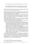
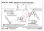
MicroFluidics Control System User Manual MFCS software©2009 Fluigent MFCS User Manual version 2.0 www.fluigent.com FLUIGENT – MFCS User Manual 2 FLUIGENT – MFCS User Manual Table of Contents 1. INTRODUCTION .............................................................................. 4 2. PACKAGE CONTENT AND REQUIRED MATERIALS .................... 5 2.1. 2.2. 2.3. PACKAGE CONTENT......................................................................................... 5 MFCS DESCRIPTION ...................................................................................... 6 REQUIRED MATERIALS .................................................................................... 6 3. INSTALLATION GUIDE ................................................................... 8 3.1. 3.2. 3.3. WARNINGS ..................................................................................................... 8 UNPACKING AND PREPARATION OF THE MFCS (WITH FLUIWELL) ........................ 8 STARTING THE MFCS ................................................................................... 13 4. BASIC SOFTWARE OPERATIONS ............................................... 15 4.1. 4.2. 4.3. 4.4. PURGE......................................................................................................... 15 PRESSURE CONTROL IN THE CHANNELS .......................................................... 16 TABS CONFIGURATIONS ................................................................................. 17 SAVE CURVES............................................................................................... 17 5. ADVANCED CONTROL OF THE MFCS ........................................ 19 5.1. MORE ABOUT MFCS CONTROL ..................................................................... 19 5.1.1. 5.1.2. 5.1.3. Coupling ...................................................................................................................... 19 Manual/auto ................................................................................................................. 19 Feedback coefficient.................................................................................................... 19 5.2. MFCS MAT (SCRIPTING SOFTWARE) ............................................................... 20 5.2.1. General description ..................................................................................................... 20 5.2.2. Description of the table ................................................................................................ 20 5.2.3. Descriptions of the Actions .......................................................................................... 21 5.2.4. Script example ............................................................................................................. 21 5.3. LABVIEW ...................................................................................................... 23 5.3.1. Labivew VI ................................................................................................................... 23 5.3.2. Labview examples ....................................................................................................... 24 ++ 5.4. C AND VBA ............................................................................................... 26 5.4.1. Function description (preliminary) .............................................................................. 26 5.4.2. VBA declarations examples : ...................................................................................... 28 5.5. ABOUT OUTPUT PRESSURIZATION ................................................................... 29 6. APPENDICES................................................................................. 30 6.1. 6.2. 6.3. 6.4. 6.5. 6.6. 6.7. TECHNICAL SPECIFICATIONS MFCS ............................................................... 30 ACCESSORIES REFERENCES AND SUPPLIERS ................................................... 31 RESPONSE AND STABILIZATION TIME .............................................................. 32 UNIT CONVERSION TABLE ............................................................................. 32 HYDRODYNAMIC RESISTANCE OF RECTANGULAR CHANNELS AND NETWORKS ... 33 MAINTENANCE .............................................................................................. 35 TRACE AND LOG FILES FORMAT ...................................................................... 36 3 FLUIGENT – MFCS User Manual 1. Introduction To your application MFCS Fluiwell Soft Tubes Reservoirs The MicroFluidic Control System (MFCS) is a High precision pneumatic pressure controller designed to handle fluid in microfluidics systems (microchannels and nanochannels, capillaries, Lab-onchips…). It allows a stable and pulsation free flow with short response time (100 ms) and a stabilization time as low as 1s. With the MFCS it is also possible to control several independent channels (up to 16 cf Labiview VI) at the same time. The user friendly softwares allow you to create scripts for complex flow patterns or dynamic coupling for user-controlled dependence between channels. Pressure Range Channel Number 4 channels 8 channels Pressure type 0 to 25 mBar 0 to 69 mBar 0 to 345 mBar 0 to 1000 mBar -25 to 0 mBar -69 to 0 mBar MFCS-4C25 MFCS-4C70 MFCS-4C345 MFCS-4C1000 MFCS-NEG4C-25 MFCS-NEG4C-70 MFCS-8C25 MFCS-8C70 MFCS-8C345 MFCS-8C1000 MFCS-NEG8C-25 MFCS-NEG8C-70 P>0 P<0 Figure 1. Available MFCS series 4 FLUIGENT – MFCS User Manual 2. Package content and required materials 2.1. Package content The MFCS package comprises following items: One MFCS unit, A power supply and a power line cable, A USB cable, * * A pneumatic Connection kit (4 soft tube adapters, 4 x 50 cm of soft tube (OD 3mm ID 1mm), a ¼ “ spanner) A quick user guide. This user manual. User manual Power supply Power line cable Soft tube Adapters MFCS softwares CD 2 m soft tube USB cable 1/4’’ Spanner** MFCS Figure 2 Package content Optional Accessories: A Fluiwell and a set of spare parts FEP Caps Fluiwell Reservoirs Figure 3 Fluiwell package If any parts are missing or damaged, please contact your local dealer or Fluigent immediately. * For a 8 channel MFCS, 8 adapters will be provided ** soon provided in the MFCS package 5 FLUIGENT – MFCS User Manual 2.2. MFCS Description USB Pressure Inlet Power Supply Rear View On / Off Switch LCD Pannel (Displays input pressure when grren button on) Front View Pressure outlet Green Button Red Button Figure 4 Front and Back views 2.3. Required Materials Using the MFCS requires the following materials: A computer : o USB 1.1 port or faster o screen resolution of 1024x768 o Intel Pentium II 500 MHz or faster o Windows2000, Windows XP. o 5 Mo of Free Hard disk space A pneumatic pressure source : o For positive pressure models : dry and non corrosive (use an air drier) dust and oil free with a pressure regulator to tune the input pressure value 0,01 µm filtered The pressure range of the pump should suit your MFCS input pressure (see Figure 3) o For negative pressure models: Use a pump in aspiration mode Pump of Local Pressure Network Norgren (F07-200-A3TG) Norgren (F72C-2GD-ST0) Air drier Particle filter 0.01µm Or Gas Cylinder Pressure Regulator Watson Smith (100300R) Only for positive pressure Figure 5 Suggested Pressure Source scheme 6 FLUIGENT – MFCS User Manual Pressure Range 0 to 25 mBar 0 to 69 mBar 0 to 345 mBar 0 to 1000 mBar -25 to 0 mBar -69 to 0 mBar Input Pressure value 500 mBar 500 mBar 800 mBar 1300 mBar - 500 mBar - 500 mBar Figure 6 : Input pressure value according to MFCS pressure range Connection to the MFCS requires either: The Fluiwell, a microfluidic interface between the MFCS and your Microdevice that uses 1/16’’ OD tube or smaller (see Figure 7) Your own connection system. To microfluidic application Controlled pressurized gas from MFCS Figure 7 Fluiwell's working principle 7 FLUIGENT – MFCS User Manual 3. Installation guide 3.1. Warnings MFCS must be used in a clean and dry environment. No liquid should enter into the device otherwise this would void the warranty. The Pressure source must be dry, dust and oil free. Use a 0,01 µm filter and a pressure regulator to insure proper input pressure. (for positive pressure models) 3.2. Unpacking and preparation of the MFCS (with Fluiwell) Please follow the next series of operation in order to set properly your MFCS. Step Indication Unpack the MFCS Photos Remarks Please check that all is in order.If any damage, please phone us or e-mail us ([email protected]). 1 Connect to the rear panel : - the usb cable - the power supply - the pressure source 2 To avoid liquid back-flow, please use protection systems such as the FLUIWELL(see Figure 7). For positive pressure models: PLEASE USE CLEAN AND DRY GAS WITH A PRESSURE REGULATOR BEFORE THE MFCS (see section 2.3) 8 FLUIGENT – MFCS User Manual Insert the MFCS softwares CD. * 3 Copy the MFCS-4C folder to desired location on your hard drive * Open the MFCS-4C folder you just copied on your hard drive. 4 Switch ON the MFCS (rear panel). 5 The red light should be bright. If not, check the power supply and the USB cable. Double click on the MFCS control icon 6 The software is ready to be used. 7 * MFCS-8C for a 8 channel device 9 FLUIGENT – MFCS User Manual 8 For positive pressure models: The pressure source should be CLEAN AND DRY and fixed to the input pressure value specified on the rear panel of your MFCS Pressure Range (mBar) 25 69 345 1000 - 25 - 69 Input Pressure value (mBar) 500 500 800 1300 - 500 - 500 Please find besides the value of the input pressure MFCS. Press the Green button and set the pressure source to the input pressure value of your MFCS. You can monitor the pressure source value on the front display. 9 The preheating will start. A preheating procedure is necessary to warm up the MFCS (10min) meanwhile you can continue with the next step Avoiding this step can decrease the pressure control stability and accuracy. When performing series of experiments, the preheating is only necessary once a day. For negative pressure models LCD panel displays the absolute value of the pressure Unpack the Fluiwell (optional accessory) Please check that the 4 toric seals are in place, before mounting the reservoirs. 10 Screw the 2 mL reservoirs on the fluiwell 11 10 FLUIGENT – MFCS User Manual Prepare your experimental setup by placing all the devices and elements you might need. The lengths of the pieces correspond to the distance between the fluiwell and the MFCS. Microfluidic chip Microscope 12 Soft tube FEP tube If you use different connectors, a list of compatible adapters is available in the appendices 1/16’’ provided connectors 13 * 4 pieces of the soft tube. You can find the references of the tubings in the appendices. * 14 4 pieces of the FEP tube. Connect the soft tubes to the fluiwell 15 Connect the FEP tubes to the top outlets. In order to avoid leaks, the fitting should be tightly screwed. The FEP tubes should be visible inside the 2 mL reservoirs. 16 * 8 pieces for MFCS-8C with 2 fluiwells 11 FLUIGENT – MFCS User Manual Now your fluiwell is ready to be connected to your microfluidic chip and to the MFCS. 17 Don’t forget to fill the reservoir with your sample ! 12 FLUIGENT – MFCS User Manual 3.3. Starting the MFCS Please proceed as follow: Step Indication Remove the protection caps from the MFCS outlets. Photos Remarks Use the provided spanner or any ¼” tools* Protection cap 1 Free outlet Tightly screw the soft tube adapters on the outlets. Soft tube adapters 2 Connect the soft tubes to the MFCS’ outlets. 3 Connect the fluiwell to your microfluidic chip, using the FEP tubes for example. A list of adapters for smaller inner diameters tubes is available in the appendices. 4 13 FLUIGENT – MFCS User Manual Fill up the 2 mL reservoirs with the appropriate fluid corresponding to the inlets of your chip. 5 At the end of the preheating countdown : - push the red button and - calibrate the MFCS by clicking on the Setup / Compensate offset. 6 Click save to MFCS to load your calibration parameters into the MFCS and close the window. In order to guarantee the accuracy of your measures we recommend you to calibrate the device every time you move it. Otherwise once a month is sufficient. The MFCS is ready to be used. 14 FLUIGENT – MFCS User Manual 4. Basic Software Operations Here you will learn how to operate the MFCS using the MFCS control interface. Pressure Handle Preheating Warning Pressure scroll Direct Button Coupling field MFCS Status Purge Button Requested Pressure field Config Tabs For negative pressure models: the software displays the absolute value of the pressure 4.1. Purge Click on the Purge button and valid the warning. A purge feature is available in channel 1. It applies maximum pressure on this channel. It suits any filling or emptying purpose. Disable the purge feature by clicking again on Purge button The Purge on green indicator will appear until you stop the purge. 1 2 15 FLUIGENT – MFCS User Manual 4.2. Pressure control in the channels For negative pressure models: the software displays the absolute value of the pressure There are two different way to modify the pressure in a channel: 1 Press Direct Control button, to activate the control of the MFCS Otherwise, orders will not be transmitted Change pressure in the channels, using the corresponding handle 2 Enter the numerical value of the pressure in the requested pressure field. 3 Shortcuts: It is possible to modify the positions of the handle using keyboard. Click on a handle, then: • Up arrow: Move the handle up by 1 steps • Down arrow: Move the handle down by 1 steps • Page up: Move the handle up by 10 steps • Page down: Move the handle down by 10 steps • Move to the top of the scale using home • Move to the bottom of the scale using end 16 FLUIGENT – MFCS User Manual 4.3. Tabs configurations For negative pressure models: the software displays the absolute value of the pressure You can use the config tabs to set different handle patterns in order to easily switch between several pressure sets by clicking on the corresponding tab. 1 The curves will follow the pressure pattern. (See MFCS mat or labview VI for automated pattern setting) 2 4.4. Save curves To save a set of curves, first choose the desired trace rate 1 Then start recording by giving a name to the curves file in save trace dialog box of the file menu. (a tick will appear) 2 17 FLUIGENT – MFCS User Manual End the record by clicking on save trace (untick) 3 4 The file is a text file that can be imported in any spreadsheet Start Title line Curves File format (see section 6.7) 5 For negative pressure models: the software displays the absolute value of the pressure 03/09/2020 08 15:2 1:39 MFCS Automat V: 1.05 MFCS S/N:0005 V:000B 15:21:39 11463 174,942 140,017 0 0,105 15:21:39 11464 175,258 140,017 0 0,105 15:21:39 11465 174,942 140,017 0 0,105 03/09/2020 Time of experiment 08 15:2 Time Step n° 2:05 --EN Pressure Channel 1 D OF TRACEPressure Channel 2 Pressure Channel 3 Pressure Channel 4 End Title line 18 FLUIGENT – MFCS User Manual 5. Advanced Control of the MFCS 5.1. More about MFCS Control 5.1.1.Coupling The coupling is a feature that creates software driven dependence between channels. Thus it is possible to increase pressure in one channel while the pressure in a second one is decreasing with the same variation. Both parallel and antiparallel coupling are possible. To set a parallel coupling between channel 1 and channel 2 choose A + for both channel in the coupling field. To achieve an antiparallel coupling just choose A- for one of the two channels. To couple more than one channel set the coupling field of each channels in consequence. . Figure 8 : Anti-parallel coupling allows changes in the pressure difference of two channels without changing the pressure sum. Parallel coupling keeps the pressure difference constant. Shortcut : It is possible to disable temporally the coupling feature of a set of channels by pressing the shift key. Then you are able to move the handles independently. 5.1.2.Manual/auto The manual mode provides a proportional control on the valves. The handles directly control the valves opening, and no regulation occurs. This mode is only adapted for special use and it will be subject to intrinsic nonlinear characteristics, hysteresis and limited reproducibility of the solenoidvalves. The auto mode provides a direct control on the pressure inside the channels. The handles set the requested pressure and the embedded regulation program will compute the order to give to the valves in order to have a stable, quick and reproducible response. 5.1.3.Feedback coefficient 400 450 400 350 400 350 300 350 250 150 100 250 250 Feed back coefficient too high 200 Optimised Feed back coefficient 200 150 150 100 50 50 0 0 5 10 15 20 0 -50 0 Feed back coefficient too low 200 100 50 -50 300 300 0 5 10 15 20 -50 0 5 10 15 20 25 30 Figure 9 : effect of the « Feed back coefficient » value on the pressure stability and response time. The MFCS Control software provides optimal pressure and flow regulation for a wide range of microfluidic applications, in particular those involving extremely low pressures and or volume flow rates (µl to pl/min). However when using large volumes, an adjustment of the feed-back 19 FLUIGENT – MFCS User Manual loop’s reactivity can be necessary to achieve an optimal operation of the MFCS. This can be achieved, independently for each channel, by changing the “feed back coefficient”. The factory setting is 5, a smaller coefficient results in a slower reaction, a higher value gives a faster response. If the feedback coefficient is to high, the regulation loop can become unstable and pressure control inside the channel is no longer possible. The optimal response is obtained just below the critical damping situation between a monotonous return to equilibrium and oscillatory overshooting. Please note that for high pressure versions of the MFCS, at the factory-setting initial value, operation is oscillation-free for small pressure changes but shows overshooting and transient oscillations for drastic pressure changes. If this overshooting is a nuisance to your application, it can be suppressed by decreasing the feedback coefficient, at the expense of the regulation speed for small pressure changes. A working compromise has to be found, the optimal value depends on several features of the connected system (volume and elasticity of tubing, hydrodynamic resistance and geometry of the microfluidic channels), and on the time constant of the phenomena under investigation. 5.2. MFCS mat (scripting software) 5.2.1.General description Chart Table (here it is blank) For negative pressure models: the software displays the absolute value of the pressure MFCS mat is a script software that allows, to create automated pattern of pressure. In the main window, you can find: A chart showing the pressure value of all the channels (here it is blank), Below the chart, the MFCS status is shown with the buttons ‘play’, ‘pause’, ‘stop’, et ‘verify program’, allowing one to play, pause, stop and verify the programme. On the right hand side, the user can fill in different actions in the table (script). 5.2.2.Description of the table MFCS In this table, there are 6 rows : Label needs a string. It is where the action « Goto label » looks for. Status Action: define the type of action Ch: define the channel number where the action is applied. Parameter: define the parameter of the action if necessary, Unit: specify the unit of the parameter (automatically set) Comment: define a comment of the current action. 20 FLUIGENT – MFCS User Manual 5.2.3.Descriptions of the Actions Actions Parameters Description Alpha Integer from 0 to 255 : n Auto Double : x End Goto label String : s Manuel Double : x Purge off Purge on Wait Double : x This value is linked to the feedback coefficient for the pressure regulation. (default value 5) Send a pressure order in mbar to the specified channel End programme Go to the line with the s string the label row The channel is control manualy without feedback control. X is equivalent to the % of alimentation of the Electrovalve. Stop Purge on channel 1 Start Purge on channel 1 The programme waits for x secondes. 5.2.4.Script example Here is an example of a script with the corresponding pressure chart. Step Label Action 1 alpha 2 alpha 3 start auto 4 wait 5 auto 6 auto 7 wait 8 auto goto 9 label Channel Parameter Unit 1 5 2 5 1 175 mb 2 s 1 210 mb 2 175 mb 2 s 2 140 mb start This is an endless loop generating a 4 seconds period square pressure signal. Example of MFCS Mat script for channel 1 and 2 250 Pressure (mBar) 200 150 Channel 1 100 Channel 2 50 0 0 50 100 150 200 250 Time (s) 21 FLUIGENT – MFCS User Manual 22 FLUIGENT – MFCS User Manual 5.3. Labview The Labview drivers are in the provided CD. The Labview library provided is embedded with a set of functions that will allow you to control the MFCS in your own Labview program. Here are a few examples of what you can achieve with this library. 5.3.1.Labivew VI Labview VI Symbol Description mfcs_close.vi Close the MFCS device and the allocated memory Handle Error in Error out mfcs_data_chan.vi Handle in Channel data Error in mfcs_get_purge.vi Handle in Error in Handle out Channel data Error out Error out Purge ON ? Handle out mfcs_get_serial.vi Get status of the purge in channel 1: True= Purge ON False= Purge OFF Get the serial number of the MFCS (0 if no MFCS connected) Handle in Error in Handle out Serial Number Error out mfcs_get_status.vi Handle in Error in Handle out MFCS Status Error out mfcs_initialisation.vi Handle in Error in mfcs_read_chan.vi Get the characteristics of the specified channel: Pressure unity (0=no sensor, 1=water inch, 2=PSI) Maximum pressure range (in the specified unity) Zero pressure value of the sensor (unsigned 12 bits) Pressure value (unsigned 12 bits) Handle in Channel number Error in Handle out Serial number Error out Get the status of the MFCS: 0= MFCS is reset. MFCS needs to be manually rearmed (switch on GREEN button) 1= Normal 2= Pressure Supply Overpressure 3= MFCS needs to be manually rearmed ater overpressure (switch on GREEN button) Initialize the MFCS device: If the serial number is not specified or equal to 0, the first MFCS device found will be initialized. If the serial number is specified, the corresponding MFCS device is initialized. Each MFCS has a unique serial number written on the back panel. The VI returns the handle and the serial number of the MFCS (0 if no MFCS found). Get the pressure value (mBar) and the Handle out measure time (ms) of the specified Pressure (mBar) channel (from 1 to 4 or 8). Measure Time (ms) Error out 23 FLUIGENT – MFCS User Manual mfcs_set_alpha.vi Handle in Channel number (default all) Alpha (default 5) Error in mfcs_set_auto.vi Alpha (default 5) Handle in Channel number (0= all) Pressure (mBar) Set the alpha value (default =5) for the specified channel (from 1 to 4 or 8): If the specified channel is 0, the same is applied to all channels. Alpha is linked to the proportional value of the PID pressure regulation. Handle out Error out Set the regulated pressure value (mBar) for the specified channel (from 1 to 4 or 8): If the specified channel number is 0, the same pressure is applied to all the channels. It is also possible to set the alpha value Handle out Error out Error in mfcs_set_manual.vi Handle in Channel number (0=all) % EV Error in mfcs_set_purge_off.vi Handle in Error in Set the electrovalve alimentation (%) for the specified channel (from 1 to 4 or 8): If the specified channel is 0, the same is applied to all channels. The manual control of the electrovalve is not recommended and the output pressure is no longer regulated Handle out Error out Disable purge feature, channel 1 can be used normally. Handle out Error out mfcs_set_purge_on.vi Handle in Error in mfcs_set_zero.vi Handle in Channel number (0=all) Zero sensor Error in Enable purge feature, channel 1 is directly connected to the pressure supply. Please use with care in order to avoid any damage to your microsystem. Handle out Error out Handle out Error out Calibrate the zero pressure value of the specified channel. This value can be estimated with mfcs_data_chan.vi. 5.3.2.Labview examples MFCS 8C control This VI is a transposition of MFCS control. It integrates MFCS control software’s functions in a Labview environment: Enter “serial number” Calibrate the MFCS if needed Set “pressure order”and “alpha” (feeback coefficient) in the channels of interests Press “purge” (channel 1 only) to fill or empty your device Press “STOP” to stop the pressure Control 2 MFCS Thanks to this Vi it is possible to control several MFCS at the same time: Enter the two serial numbers Select the MFCS of interest with the 1/2 switch of the “INPUT” box. Set channel number, pressure order, appropriate Alpha (feedback coefficient). Press STOP button to stop pressure 24 FLUIGENT – MFCS User Manual Calibration The Calibration process can also be in operated from Labview interface Set pressure and alpha analog This example allows you to set an order (pressure and feedback coefficient) and then to read the result on an analog curve Set pressure digital This example allows you to set a pressure order and monitor the result on a numerical display 25 FLUIGENT – MFCS User Manual 5.4. C++ and VBA 5.4.1.Function description (preliminary) Here is a global description of the functions provided with the library. mfcs_initialisation Initialize the USB for the MFCS. If the Serial Number is not specified or equal to 0, the first MFCS device found will be initialized. If the Serial Number is specified, the MFCS device with this Serial Number is initialized. Each MFCS has a unique Serial Number written on the back panel. The vi returns the handle and a boolean that confirms that the USB initialized correctly. mfcs_close Close the MFCS device and the allocated memory. mfcs_set_purge_on Connect the channel 1 output directly to the pressure supply. This function should be used with care as it can cause damage to the microsystems connected. mfcs_set_purge_off Disconnect the channel 1 output from the pressure supply. Channel 1 can be used normally. mfcs_get_purge Get the status of the purge: - TRUE= purge ON, - FALSE= purge OFF mfcs_get_status Get the status of the MFCS: -1= Trouble in the MFCS connections (USB or electric alimentation) 0= MFCS is reset. MFCS needs to be manually rearmed (green switch on the front panel), 1= Normal, 2= Pressure Supply Overpressure, 3= MFCS needs to be manually rearmed after overpressure (green switch on the front panel). mfcs_read_chan Get the pressure value (mBar) and the measure time (ms) of the specified channel (from 1 to 4 or 8). mfcs_data_chan Get the characteristics of the specified channel: - Pressure Unity (0= no captor, 1= water inch, 2= PSI), - Maximum Pressure range (in the specified unity), - Zero pressure value of the captor (unsigned 12 bits), - Pressure value (unsigned 12 bits) - Chrono value (unsigned 16 bits). mfcs_get_serial Get the Serial Number of the MFCS. mfcs_set_auto Set the regulated pressure (mBar) for the specified channel (from 1 to 4 or 8). If the specified channel is 0, the same is applied to all channels. mfcs_set_alpha Set alpha value (default value =5) for the specified channel (from 1 to 4 or 8). If the specified channel is 0, the same is applied to all channels. Alpha is linked to the proportional value of the PID. mfcs_set_manual Set the electrovalve alimentation (%) for the specified channel (from 1 to 4 or 8). If the specified channel is 0, the same is applied to all channels. The manual control of the electrovalve is not recommended and the output pressure is no longer regulated. mfcs_set_zero Save in the EEPROM the zero pressure value of the specified channel. 26 FLUIGENT – MFCS User Manual The following array gives an algorithmic description of the previous functions. function return parameter Comment mfcs_initialisation UL handle US serial number Initialise USB connection and look for a MFCS with the specified serial number. handle = 0 if no USB connection mfcs_close B OK UL handle Close USB connection mfcs_read C error UL handle Read string on the interface S string mfcs_write C error UL handle Write string on the interface S string mfcs_set_purge_on C error UL handle Open purge on channel 1 mfcs_set_purge_off C error UL handle Close purge on channel 1 mfcs_get_purge C error. UL handle Get the purge state PB purge state mfcs_get_status C error. UL handle PC Status mfcs_read_chan C error. UL handle Get MFCS status 0 if the MFCS is reset 1 if normal 2 if overpressure 3 if MFCS needs to be rearmed. : Read the pressure value (mBar) of the specified channel with the timing (time unit 25ms). C channel PF pressure PUS chrono mfcs_data_chan C error UL handle C channel PC sensor unit PUS sensor max PUS zero Read the sensor data : - sensor unit : 0 = no sensor, 1 = "H2O (2.4908 mBar) 2 = psi (68.946 mBar) - full scale in pressure unit - zero value sensor (U12) - direct pressure measure (U12) - chrono (time unit 25ms) PUS measure PUS chrono mfcs_get_serial C error UL handle Get the serial number of the MFCS PUS Serial mfcs_set_auto C error US handle Regulate pressure (mBar) on the specified channel. (if 0, the same for all channel) C channel F pressure 27 FLUIGENT – MFCS User Manual mfcs_set_alpha C error UL handle C channel C alpha mfcs_set_manual C error UL handle Set alpha value (U8). This value is linked to the PID performance. The recommended value is 50 for MFCS device sold with MFCS_Control V1.05. For more recent version (V1.06 and V1.07) the default value is 5 and a preheating of the electro-valves is necessary (45% alimentation for 10 min). Set electro-valve voltage (%) on the specified channel. (if 0, the same for all channel) C channel F EV mfcs_set_zero C error UL handle Save Zero sensor value on the firmware. To get this value, use mfcs_data_chan (PUS mesure) C channel US Zéro Definition of [C error]: - 0 = OK, - 1 = USB closed - 2 = Wrong channel symbol bits UL US PUS S C PC B 32 16 32 32 8 32 8 PB F PF 32 32 32 C++ unsigned long unsigned short pointer on unsigned short char[] unsigned char unsigned char * char for boolean result 1 = true, 0 = false pointer on boolean float pointer on float Labview VBA (U32) (U16) (U16) by address (abc) (U8) (U8) by address (U8) ByVal Long ByVal Integer ByRef Integer ByVal String ByVal Byte ByRef Byte ByVal Byte (U8) by address (SGL) (SGL) by address ByRef Byte ByVal Single ByRef Single NB : 1) in Visual Basic, all values are signed 2) After calling mfcs_initialisation, a delay (0.5s) must be set before calling other functions, 3) A mfcs_close must be called before leaving the application, to avoid Windows error. 5.4.2.VBA declarations examples : Public Declare (ByVal i Public Declare (ByVal H Public Declare (ByVal H Public Declare (ByVal H Public Declare (ByVal H Public Declare (ByVal H Public Declare (ByVal H Public Declare Function mfcs_initialisation Lib "d:\mfcs\mfcs_vb.dll" As Integer) As Long Function mfcs_close Lib "d:\mfcs\mfcs_vb.dll" As Long) As Byte Function mfcs_read Lib "d:\mfcs\mfcs_vb.dll" As Long, ByVal S As String) As Byte Function mfcs_write Lib "d:\mfcs\mfcs_vb.dll" As Long, ByVal S As String) As Byte Function mfcs_set_purge_on Lib "d:\mfcs\mfcs_vb.dll" As Long) As Byte Function mfcs_set_purge_off Lib "d:\mfcs\mfcs_vb.dll" As Long) As Byte Function mfcs_get_purge Lib "d:\mfcs\mfcs_vb.dll" As Long, ByRef C As Byte) As Byte Function mfcs_get_status Lib "d:\mfcs\mfcs_vb.dll" 28 FLUIGENT – MFCS User Manual (ByVal H As Long, ByRef C As Byte) As Byte Public Declare Function mfcs_read_chan Lib "d:\mfcs\mfcs_vb.dll" (ByVal H As Long, ByVal Chan As Byte, ByRef P As Single, ByRef Chrono As Integer) As Byte Public Declare Function mfcs_data_chan Lib "d:\mfcs\mfcs_vb.dll" (ByVal H As Long, ByVal Chan As Byte, ByRef Su As Byte, ByRef Sm As Integer, ByRef Zr As Integer, ByRef Ms As Integer, ByRef Chrono As Integer) As Byte Public Declare Function mfcs_get_serial Lib "d:\mfcs\mfcs_vb.dll" (ByVal H As Long, ByRef Serial As Integer) As Byte Public Declare Function mfcs_set_auto Lib "d:\mfcs\mfcs_vb.dll" (ByVal H As Long, ByVal Chan As Byte, ByVal P As Single) As Byte Public Declare Function mfcs_set_alpha Lib "d:\mfcs\mfcs_vb.dll" (ByVal H As Long, ByVal Chan As Byte, ByVal Alpha As Byte) As Byte Public Declare Function mfcs_set_manual Lib "d:\mfcs\mfcs_vb.dll" (ByVal H As Long, ByVal Chan As Byte, ByVal Ev As Single) As Byte Public Declare Function mfcs_set_zero Lib "d:\mfcs\mfcs_vb.dll" (ByVal H As Long, ByVal Chan As Byte, ByVal Zero As Integer) As Byte 5.5. About output pressurization Pin Pout Pin - Pout Atmosphere In order to operate in an optimized range of the pressure full scale, it is recommended to work with differential pressure. Indeed, by pressurizing both input and output of a channel properly, the pressure inside the channel would be equal to the differential of the output and the input pressures. 29 FLUIGENT – MFCS User Manual 6. APPENDICES 6.1. Technical Specifications MFCS MFCS 25 mBar Characteristics Input pressure range Output pressure precision Min. - Typ. 500 <2.5 % Max. 600 - Unit mbar full scale Min. output pressure step Max. output pressure Operation temperature range Input voltage range Weight Power consumption -10 23 1.9 - 23 25 25 24 - 50 25 2.25 <16 µbar mbar °C V kg W Comment Better if calibrated (see Quick start) Depends on model MFCS 70 mBar Characteristics Input pressure range Output pressure precision Min. - Typ. 500 <2.5 % Max. 600 - Unit mbar full scale Min. output pressure step Max. output pressure Operation temperature range Input voltage range Weight Power consumption -10 23 1.9 - 63 69 25 24 - 50 25 2.25 <16 µbar mbar °C V kg W Comment Better if calibrated (see Quick start) Depends on model MFCS 350 mBar Characteristics Input pressure range Output pressure precision Min. - Typ. 800 <2.5 % Max. 900 - Unit mbar full scale Min. output pressure step Max. output pressure Operation temperature range Input voltage range Weight Power consumption -10 23 1.9 - 0.32 343 25 24 - 50 25 2.25 <16 mbar mbar °C V kg W Comment Better if calibrated (see Quick start) Depends on model MFCS 1000 mBar Characteristics Input pressure range Output pressure precision Min. - Typ. 1.3 <2.5 % Max. 1.4 - Unit bar full scale Min. output pressure step Max. output pressure Operation temperature range Input voltage range Weight Power consumption -10 23 1.9 - 0.95 1033 25 24 - 50 25 2.25 <16 mbar mbar °C V kg W Comment Better if calibrated (see Quick start) Depends on model 30 FLUIGENT – MFCS User Manual 6.2. Accessories references and suppliers Designation Reference and Supplier Remark USB Cable CD Software User manual Blue tubing (OD=1/32’’, ID=250µm) FEP tubing (OD=1/16’’, ID=800µm) Upchurch Scientific : 1581 Fisher : A28556 Glass capillary (OD=360µm’, ID=100µm) Polymicro technologies : TPS100375 Green Sleeves (1/16˝ to 360µm) Upchurch Scientific : F-242X Green Sleeves (1/16˝→ 1/32˝) Upchurch Scientific : F-247X 10-32 Peek Fitting Nuts Upchurch Scientific : F-120 soft tubing (1x3mm) Fisher : A31309 Micrew reservoir 2 mL Fisher : W14437 31 FLUIGENT – MFCS User Manual 6.3. Response and Stabilization Time Here are the graphic definition of response time and stabilization time. Pressure 5% StabilizationTime 100% Response Time Ti 6.4. Unit Conversion Table value (↓ ↓) = factor kPa xunit (→ →) 1 1 kPa 100 1 bar 6.895 1 psi 0.249 1 inch H2O bar psi inch H2O 0.01 1 68.95x10⁻³ 2.49x10⁻³ 0.145 14.5 1 3.612x10⁻² 4.016 401.6 27.68 1 Example: 10 kPa = 10 kPa x 0.01 bar/kPa = 0.1 bar 32 FLUIGENT – MFCS User Manual 6.5. Hydrodynamic Resistance of Rectangular Channels and Networks Pressure difference p, the volume flow rate Q, or the averaged velocity u and the friction coefficient C are related through -4 with channel dimensions a and b with a/b>>1, channel length l and viscosity µ (= 9.5 10 Pa s for H2O at 25°C). The relation between the friction C and the aspect ratio a/b can be calculated [Stone, Stroock, Ajdari, Ann. Rev. Fluid. Mech., 2004]: with Figure 6: This graph shows the friction coefficient as a function of the aspect ratio of the channel and can be used to estimate the flowrate due to a given pressure difference. Typical values are: =1 -> C=0.03512; C=0.05708; =10 -> C=0.07688. Example: A channel of 10x100µm with a length of 10mm contains 0.01 µl. Applying a pressure difference of 10 Pa (=100 µbar) gives a volume flow rate of about Q=0.0005 µl/min and an averaged flow velocity of u = 5 µm/min. A pressure of 100'000 Pa (=1 bar) is 10'000 times higher thus the flow rate and velocity are also 10'000 times increased. Since Ohm's law also applies to flow of other particles than electrons (e. g. water) we can transfer the formulas. For one single channel we have for the volume flow Q as a function of the externally applied pressure difference p and the resistance R: Q=p /R, Q=abu. The pressure pc at an arbitrary position in a single channel with partial resistances R1 and R2 of the two halves of the channel is: 33 FLUIGENT – MFCS User Manual The total resistance is R=R1+R2, the flow yields Q=(p1−pc)/R1, R2 is equivalent. If the two parts are of equal resistance (equal length and diameter) we find the well known average value: pc=(p1+p2)/2. For three channels (p1, p2, p3 and R1, R2, R3) joining in one point with pressure pc we find using the continuity equation (the sum over all Qs going into one knot vanishes) The corresponding flow in channel 1 as an example can be obtained with Ohm's law: Q1=(p1−pc)/R1, the other values are equivalent. To obtain the corresponding formulas for n channels joining in one knot, the latter formula can be generalized: More complex geometries can be calculated using well-known methods in analogy to electrical resistor networks (pressure is equivalent to the electric potential, flow is equivalent to the current, and flow resistance of a channel plays the same role as the Ohm's resistance). 34 FLUIGENT – MFCS User Manual 6.6. Maintenance The MFCS is designed as a very robust device for usage in laboratory and industrial environment and easy to maintain. For optimal accuracy, calibration should be performed regularly (typically every month) or after the MFCS has been displaced, in order to maintain optimal accuracy of the results and compensate for offset drift of the pressure sensors. The housing can be cleaned with a moisty soft tissue, iso-propanol or window-cleaning products. Avoid aggressive organic solvents as acetone or chloroform or abrasive cleaning products. Please use the following form if you have problems or suggestions with your MFCS device or software and send it to us by fax or e-mail. 35 FLUIGENT – MFCS User Manual 6.7. Trace and Log files format MFCScontrol allows a complete real time recording of all settings and measured pressure values during operation. 11.07.2005 17:39:03 MFCS S/N:0003 V:000.011 15885 18.424 0.426 5.146 20.560 15886 18.424 0.426 5.100 20.477 15887 18.386 0.395 5.100 20.454 15888 18.371 0.426 5.123 20.583 15889 18.485 0.395 5.100 20.583 15890 18.462 0.426 5.100 20.500 15891 18.402 0.426 5.146 20.500 15892 18.333 0.395 5.123 ... Figure 10: an example of a Trace file. The trace file format consists of a header line and a data block. The header line is composed of the starting date and time, serial number of the connected unit and version number of the MFCScontrol software. The data block is composed of lines carrying a time stamp (absolute time and the internal step number) and the 4 (8) pressure values. '#N/A' means information lost (e. g. transient transmission failure). When using this option, avoid the creation of oversized data files. Adjust the storage frequency according to the needs (see pull down menus). 11.07.2005 11.07.2005 11.07.2005 11.07.2005 11.07.2005 11.07.2005 11.07.2005 11.07.2005 11.07.2005 11.07.2005 11.07.2005 11.07.2005 11.07.2005 17:27:38 17:27:43 17:27:43 17:27:43 17:27:43 17:27:43 17:27:43 17:27:43 17:27:45 17:27:45 17:27:46 17:27:46 17:27:46 --BEGIN OF LOG-AUTO. Chan. 1 : AUTO. Chan. 1 : AUTO. Chan. 1 : AUTO. Chan. 1 : AUTO. Chan. 1 : AUTO. Chan. 1 : AUTO. Chan. 1 : AUTO. Chan. 1 : AUTO. Chan. 1 : AUTO. Chan. 1 : AUTO. Chan. 1 : AUTO. Chan. 1 : 2196 2221 2246 2283 2332 2381 2406 2715 2727 2739 2739 2739 11.07.2005 17:39:27 --END OF LOG-Figure 11: an example of a Log file. 36 FLUIGENT – MFCS User Manual ALPHA AUTO Chan. X : YYYYY Chan. X :YYYYY --BEGIN OF LOG---END OF LOG-MANUAL Chan. X : YYYYY Order: set value to YYYYY in Channel X Order: set value YYYYY in Channel X in feed back mode Order: start logging Order: stop logging Order: set value YYYYY in Channel X in manual mode PURGE OFF PURGE ON USB OFF USB ON ZERO Chan. X : YYYYY Order: open purge valve Order: close purge valve Order: close USB channel Order: open USB channel Order: set zero value YYYYY on channel X Table 2: commands sent from the computer to the MFCS. mfcs exceeding input pressure mfcs operating mfcs purge off MFCS S/N:---- V:---mfcs purge on mfcs reset detected Message: input pressure exceeds threshold value Message: system is operating normally Message: purge is switched off Message comprising serial and version number Message: purge is switched on Message: system has realized activation of reset signal (button, processor reset line) Table 3: commands sent from the MFCS to the computer. . 37 FLUIGENT – MFCS User Manual Fluigent tel. : +33(0)15373-1551 fax. : -1552 e-mail : [email protected] MFCS date : SUGGESTIONS /DYSFUNCTIONS Name : ____________________________________ Urgent : yes Suggestion Society : __________________________________ Dysfunctions Device/Version : ____________________________________________________ Software/Version : ______________________________________________________ ____________ Menu or concerned function : _______________________________________________________ __________________________________________________________ Error code, if available : DESCRIPTION (please cite error messages, operation before error, operation to quit error message, add screen shots if possible) Don't write in this field, please. 38 FLUIGENT – MFCS User Manual FLUIGENT Pépinière Hôpital COCHIN 29, rue du Faubourg St Jacques 75014 Paris France Phone : +331 46 33 16 28 Fax: +331 46 33 16 68 website: http://www.fluigent.com e-mail: [email protected] 39