1
Tiptilt User Manual
1 of 24
http://www.mso.anu.edu.au/observing/2.3m/tiptilt/tipuser.html
USER MANUAL
FOR THE
TIPTILT INFRARED SECONDARY
ON THE 2.3m TELESCOPE
Written Mick Brooks, Jan van Harmelen and Peter Wood
Version 1-4
Date August 1998
27/08/05 11:30 PM
Tiptilt User Manual
2 of 24
http://www.mso.anu.edu.au/observing/2.3m/tiptilt/tipuser.html
Table of Contents
1 User Guide *
1.1 Introduction *
1.2 Starting up *
1.3 Calibration *
1.3.1 Initial calibration (only at the start of a run) *
1.3.2 Regular calibration *
1.4 DO file examples *
1.4.1 Standard or other bright stars *
1.4.2 Observing a list of objects *
1.4.3 Mosaicing *
1.4.4 Dithering *
1.4.5 Using the FIND option *
1.4.6 Not bothering to use tiptilt *
1.4.7 Spectroscopy *
1.5 Summary: Quick guide to using tiptilt *
1.6 Known Bugs *
2 Reference *
2.1 The Solaris Interface *
2.1.1 Starting up Tiptilt *
2.1.2 The Control Window *
2.1.3 The Status Window *
2.1.4 Centroid Statistics *
2.1.5 Advanced Settings *
2.2 The Telescope Control System *
2.2.1 Tiptilt Commands *
27/08/05 11:30 PM
Tiptilt User Manual
3 of 24
http://www.mso.anu.edu.au/observing/2.3m/tiptilt/tipuser.html
2.2.2 Command Reference Guide *
2.2.3 Changes to Existing Commands *
2.3 Using Tiptilt with CASPIR *
2.3.1 New Commands *
2.3.2 Changes to Existing Commands *
2.3.3 New DO File Parameters *
1. User Guide
1. Introduction
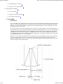
The essential hardware components of the 2.3m telescope, tiptilt secondary mirror and infrared system are shown in
Figure 1.1. The aim of the tiptilt system is to counteract any motion of the star caused by translational seeing and
guide errors. To do this, the tilt of the secondary mirror can be adjusted rapidly to move the image of a star in the
focal plane by up to 10 arcseconds.
In order to know how to move the secondary mirror, it is necessary to detect a guide star in the focal plane and tilt
the secondary mirror to correct any deviation of the guide star from a designated reference position. The detection of
the guide star is done with the tiptilt CCD. It uses the light shortward of 0.85 microns which is split off from the
CASPIR beam with a dichroic beam splitter. The IMB focus is used to make sure the CASPIR array and the CCD
are simultaneously in focus. Since guide stars need to be obtained over a wide field, the tiptilt CCD is carried on an
X-Y stage that can move up to +/- 2.5 arcminutes.
When set to correct mode, the system reads out a small portion of the CCD called the subframe at up to 110 times
per second. The guide star will be close to the centre of the subframe. The centroid of the guide star image is
calculated, compared with its reference position at the centre of the subframe, and the positional error is converted
into drive voltages for the mirror actuators.
27/08/05 11:30 PM
Tiptilt User Manual
4 of 24
http://www.mso.anu.edu.au/observing/2.3m/tiptilt/tipuser.html
Figure 1.1: Hardware components of the 2.3m telescope, tiptilt secondary mirror and
infrared system
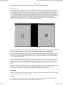
The computer interface of the tiptilt system runs on the Sun workstation "misty". A small Ximtool window shows
the continually updating image taken by the tiptilt CCD (Figure 1.2). Also visible on this window is a small blue box
(typically 8x8 pixels), the subframe. When operating in acquire mode, the whole CCD window of 64x64 pixels is
continually updated. Each CCD pixel is 0.6 arcsec square and the visible CCD field is 38x38 arcsec. When operating
in correct mode, the tiptilt system only displays the subframe: it is always at the centre of the window regardless of
the position of the subframe (blue box) during acquire mode. (Note that the 64x64 pixel display is half of the 64x128
frame transfer CCD, the top 20% of whose store area is exposed to light during readout. This shows up as a
semicircular bright patch on the top 20% of the image when the sky is bright, and as streaked star images if a star
falls on this area during readout. Never try to guide on these streaked stars.)
Figure 1.2: The Ximtool window during acquire mode (left), and during correct mode (right). Note that the
image orientation is north up, east to the right. This is flipped left-right from the CASPIR display.
In a typical mode of operation, the user will specify a tracking coordinate for a science object which will cause the
telescope to move and put the science object at the centre of the CASPIR array. The user will also specify a guide
coordinate for the guide star which will cause the XY stage, or possibly the subframe, to move so that the guide star
is near the centre of the subframe
There are a number ways in which tiptilt can be operated: from the GUI on misty, via commands at the telescope
console, or via CASPIR DO files. In the latter case, which is undoubtedly the most efficient, the infrared computer
MOPRA controls the telescope, CASPIR and tiptilt. Examples of DO files for typical observations are given in
Section 1.4 below. It is recommended that these examples be modified for by the observer for his or her particular
objects.
Sections 1.2 and 1.3 provide a brief guide on use of the tiptilt system. Section 1.4 gives DO file examples covering
most types of observations. A summary is given in Section 1.5. The latter half of the manual, Section 2, is a
Reference Guide giving details of all the possible commands associated with the tiptilt system.
2. Starting up
Make sure "Telescope Systems" power is on (top left of telescope console: automatically started if telescope startup
sequence is run). Start the tiptilt system by typing
tiptilt &
in a window on the Sun workstation misty. Wait a minute or so for the various windows to appear. In particular,
there should be an Ximtool window with a rapidly updating image from the CCD.
27/08/05 11:30 PM
Tiptilt User Manual
5 of 24
http://www.mso.anu.edu.au/observing/2.3m/tiptilt/tipuser.html
Make sure that you have entered the following on the telescope console:
enlist tt
enlist ir
configure effective_wavelength 1700 (a mean wavelength - the exact value is not critical)
configure guider_wavelength 700
On the CASPIR control console type the following:
caspir/tiptilt
caspir/stage_offset
3.
Calibration
1. Initial calibration (only at the start of a run)
Before doing any observing, you must properly calibrate the telescope and guider systems, in particular, the telescope apertures and
pointing, and the guider stage. This is done with the following procedure:
TRACK a bright object (say, a standard star) with a known coordinate.
Focus the telescope on the CASPIR array.
Centre the star on the CASPIR display, pixel (128,128). For fine adjustment, use the CASPIR ZOOM function.
Use the CALIBRATE APERTURE command to define an aperture. Follow the steps of the calibration procedure as
prompted. Remember on subsequent nights to select the aperture (eg. A) you want to use (by default, it is the previous
aperture used).
Centre the star in the aperture once more and issue the CALIBRATE POINTING command.
If the guider stage is positioned too far from the field centre, the star may not appear on the Tiptilt CCD display. In this
case, try issuing the command IMB/XY_HOME on the CASPIR command line. If the star still doesn’t appear on the
Tiptilt display, try the commands IMB/X_ABS =-548 and IMB/Y_ABS=-99.
Focus the star in the Tiptilt display by using the IMB/FOCUS command on the Infrared system.
Issue the CALIBRATE STAGE command on the telescope console and follow the steps of this procedure as prompted.
If the subframe was positioned over the star and is now in an inconvenient position, it can be brought to the centre with the
Telescope command: TIPTILT/TRACK/REF=(32,32). (Or any other values desired.)
All the above can be achieved (in principle, more quickly and accurately) by the single command CALIBRATE
TIPTILT/ALL on the telescope console. Have a star centred on the CASPIR array and visible on the tiptilt CCD before
issuing the command: then follow the instructions.
1. Regular calibration
The IMB focus and the aperture calibration should not need to be done more than once per run. On subsequent nights, make sure
that the calibrated aperture is selected (with the command APERTURE/SHOW). CALIBRATE POINTING needs to be done on a
regular basis, as for non-tiptilt observing. The stage should not normally require recalibration. However, if CALI STAGE/ADJUST
is used during spectral observations (section 1.4.7.1), the stage centering may be significantly altered and a CALI STAGE should
be done before recommencing imaging observations.
1. DO file examples
The most efficient way to use Tiptilt is via CASPIR DO files. Some examples of DO files which cover common
tasks are listed here. In all the examples, it is assumed the system has been properly calibrated with the
CALIBRATE APERTURE, CALIBRATE POINTING and CALIBRATE STAGE commands. You should also
have typed CAS/TIP and CAS/STAGE on MOPRA. Appropriate correct times for tiptilt (tt_ct) for guide stars of
known magnitude can be obtained from the table near the end of this manual.
1. Standard or other bright stars
RUN cy=100 tim=0.3 dec=+12 fil=K tt_mo=correct tt_ct=10 gra=0 gdec=0 stage
RUN dec=-12
This command sequence is for doing a bright standard star in K. The file is suitable for any object that is
bright enough to act as the tiptilt guide star. It is assumed that a TRACK/COORD command has been issued
27/08/05 11:30 PM
Tiptilt User Manual
6 of 24
http://www.mso.anu.edu.au/observing/2.3m/tiptilt/tipuser.html
on the telescope console. The DO file first sets CASPIR to an exposure time of 0.3 seconds and 100 cycles.
It sets the tiptilt correct mode exposure time to 10ms (tt_ct=10) and tells the system to use a guide coordinate
with zero offsets from the tracking coordinates (ie. use the tracking object for correcting). It then offsets the
telescope by 12 arcseconds in declination, starts tiptilt correcting and begins the CASPIR run. The second
line does much the same thing but with the telescope offset by -12 arcseconds in declination. Note that in
both cases the X-Y stage will be moved to keep the object in the tiptilt subframe. The parameter tt_ctime
could be increased for less bright objects.
2. Observing a list of objects
DARK tim=2 cy=30 rep=1 met=2 tiptilt stage acqx=2 acqy=2 acqdx=60 acqdy=60 ttx=28 tty=28 ttdx=8 ttdy=8 tt_mod=acquire tt_at=100 gra=0 gdec=0 nott_find
!
RUN "STAR1",tra="18 00 33.8 -28 01 10 j2000" dec=+12 filt=k tt_m=correct guide="18 00 37.0 -28 01 58 j2000" tt_ct=20
RUN dec=-12
RUN "STAR2",tra="18 29 02.1 -30 21 11 j2000" dec=+12 guide="18 29 05.0 -30 21 59 j2000" tt_ct=10
RUN dec=-12
RUN "STAR3",tra="18 30 49.0 -30 24 10 j2000" dec=+12 tt_m=acquire
RUN dec=-12
RUN "STAR4",tra="18 29 12.9 -30 21 43 j2000" dec=+12 tt_m=correctguide="18 29 05.0 -30 21 59 j2000" tt_ct=10
RUN dec=-12
The first DARK line is used to make sure the tiptilt parameters are set to suitable values. The tiptilt subframe
is set to 8x8 pixels (ttdx=8, ttdy=8), and the acquire box is set to the entire CCD except for edge columns
and rows (acqx=2 acqy=2 acqdx=60 acqdy=60). The nott_err flag is set so that the observation will continue
if a suitable guide star is not found. Note that the DARK exposure will be done with the telescope pointing at
the tracking coordinate in operation when the DO command is issued.
For the first RUN on each tracking object, the object name and coordinates are defined, as are the guide
coordinates if available (in this example, there is a guide star available within 2.5 arcmin of all tracking
objects but the third). Note that the track and guide coordinates remain in operation on subsequent lines until
explicitly changed (the dec=-12 exposure is done with the same guide star as the dec=+12 exposure in this
example, the stage moving between exposures to keep the guide star in the tiptilt subframe). . For STAR3, no
guide coordinate is specified, so the guide coordinates for the previous object will be assumed. The stage will
not be able to move to this position with the telescope pointing at the tracking object, so a stage-out-of-range
error will be printed on the telescope console. This does not stop operation, and the exposure will be done
without tiptilt.
The filter and tiptilt mode are defined by the first RUN command of the DO file and remain in operation for
the remainder of the DO file. The tiptilt exposure time is specified for each guide object (see the Table at the
end of the Manual for appropriate values). Any number of objects and filters could be added to the list, each
object with or without a guide star .
3. Mosaicing
DARK tim=2 cy=30 rep=1 met=2 tiptilt stage acqx=2 acqy=2 acqdx=60 acqdy=60 ttx=28 tty=28 ttdx=8 ttdy=8 tt_mod=acquire tt_at=100 gra=0 gdec=0 nott_find nott_error
!
27/08/05 11:30 PM
Tiptilt User Manual
7 of 24
http://www.mso.anu.edu.au/observing/2.3m/tiptilt/tipuser.html
RUN "GRB source", tra="1 18 45.0 -5 26 00 j2000" dec=+120 ra=120 tt_m=correct guide="1 18 38.6 -5 27 21 j2000" filt=k tt_ct=25
RUN dec=+120 ra=0
RUN dec=+120 ra=-120
RUN dec=+0 ra=+120
RUN dec=+0 ra=0
RUN dec=+0 ra=-120
RUN dec=-120 ra=+120 guide="1 18 54.6 -5 27 21 j2000" tt_ct=10
RUN dec=-120 ra=0
RUN dec=-120 ra=-120
In a mosaic, guide stars may only be available in some positions (a guide star must exist within 2.5
arcminutes of the position, in RA and Dec). If there is no accessible guide star, then the exposure will be
done without tiptilt. In this sort of file, guide stars are added to appropriate lines if available (with either a
guide= command, or gra= and gdec= commands, and a tt_ctime). The first DARK line sets appropriate
tiptilt parameters while the first RUN line sets the filter and correct mode.
4. Dithering
DARK tim=2 cy=30 rep=1 met=2 tip stage acqx=2 acqy=2 acqdx=60 acqdy=60 ttx=28 tty=28 ttdx=8 ttdy=8 tt_mod=acquire tt_at=100 gra=0 gdec=0
!
RUN "Sgr_A*",tra="17 42 29.5 -28 59 18 b1950" ra=+4.75 dec=+4.75 guide="17 45 31.4 -28 59 53 j2000" tt_m=correct tt_ct=30 fi=k
RUN ra=+4.75 dec=-4.75
RUN ra=-4.75 dec=+4.75
RUN ra=-4.75 dec=-4.75
RUN "LWHM32",TRA="17 41 35.1 -29 05 00 B1950" RA=+4.75 DEC=+4.75 guide="17 44 46.6 -29 07 17 j2000" tt_ct=40
RUN ra=+4.75 dec=-4.75
RUN ra=-4.75 dec=+4.75
RUN ra=-4.75 dec=-4.75
The DARK is done first, setting all the relevant parameters. Then some dithered RUN lines follow, the first
RUN on each object setting the filter as well as defining the tracking and guide coordinates and selecting
correct mode.
5. Using the FIND option
DARK gra=0 gdec=0 ttx=28 tty=28 ttdx=8 ttdy=8 acqx=2 acqy=2 acqdx=60 acqdy=60 nott_err tt_mod=acquire tt_at=70 tt_ct=100 cy=100 ti=0.3 stage tip tt_find
DARK cy=60 ti=1
27/08/05 11:30 PM
Tiptilt User Manual
8 of 24
http://www.mso.anu.edu.au/observing/2.3m/tiptilt/tipuser.html
!
RUN "D18465" ,TRA="18 46 34.6 -7 17 18 B1950" FIL=K TI=0.3 CY=100 DEC=-10 tt_fi gra=0 gdec=0
RUN FIL=H
RUN FIL=J TI=1 CY=60
RUN "D17208" ,TRA="17 20 53.6 -37 2 47 B1950" FIL=K TI=0.3 CY=100 DEC=+10 tt_fi gra=0 gdec=0
RUN FIL=H
RUN FIL=J TI=1 CY=60
RUN "D17223" ,TRA="17 22 23.6 -37 41 44 B1950" FIL=K TI=0.3 CY=100 DEC=-10 tt_fi gra=0 gdec=0
RUN FIL=H
RUN FIL=J TI=1 CY=60
The DO file in this example does sequential observations of a series of objects using tiptilt if a guide star
turns up on the tiptilt CCD. A large tt_ct is used to increase the chance of a guide star being found, at the
expense of image size reduction. If no suitable guide star appears, the observation is done without tiptilt
operating. The important distinction between tt_find and nott_find is described below.
Tiptilt is normally run with nott_find in operation (this is the default). With nott_find, the telescope moves to
bring the brightest star in the acquire box (assumed to be the guide star) to the centre of the tiptilt subframe:
consequently, the tracking object is put on an exactly defined part of the CASPIR array. However, when
tt_find is used, tiptilt moves the subframe onto the brightest star in the acquire box (normally the full CCD)
and starts correcting there, leaving the tracking object on the part of the CASPIR array that it was put by the
telescope in response to the TRACK command issued by the DO file. Generally, nott_find is not terribly
useful because the chance of having a bright guide star in the small CCD frame is small.
6. Not bothering to use tiptilt
Any of the files above could be used without tiptilt if the notiptilt keyword is added to the first line instead of
the tiptilt keyword. For example:
DARK gra=0 gdec=0 ttx=28 tty=28 ttdx=8 ttdy=8 acqx=2 acqy=2 acqdx=60 acqdy=60 nott_err tt_mod=acquire tt_find tt_at=70 tt_ct=100 cy=100 ti=0.3 stage notip
DARK cy=60 ti=1
!
RUN "D18465" ,TRA="18 46 34.6 -7 17 18 B1950" FIL=K TI=0.3 CY=100 DEC=-10 tt_fi gra=0 gdec=0
RUN FIL=H
RUN FIL=J TI=1 CY=60
7. Spectroscopy
1. Short-slit grism spectroscopy
RUN ra=+4 dec=0 tt_mode=correct tip nostage
27/08/05 11:30 PM
Tiptilt User Manual
9 of 24
http://www.mso.anu.edu.au/observing/2.3m/tiptilt/tipuser.html
RUN ra=-4 dec=0 tt_mode=correct
RUN ra=-4 dec=0 tt_mode=correct
RUN ra=+4 dec=0 tt_mode=correct
Tiptilt can greatly increase the photon flux passing through a narrow slit in spectroscopic mode. It is
important that the science object falls in exactly the central position of the slit with tiptilt running but
before any offsetting is done. This position is close to pixel (128,128) - see the CASPIR manual for
determining its position. Two methods for getting the science object into the centre of the slit are
given below. The first is probably more simple. (CASPIR will need to be in an imaging mode in
order that the user can see the position of the science object: switch back to spectroscopic mode when
positioning is completed. If the object being observed is bright enough that the spectrum can be seen
on the CASPIR idle display, then the intensity of the spectrum can be peaked up in the procedures
below, while CASPIR remains in spectroscopic mode).
Method 1
1. Specify the guide and track coordinates and put tiptilt in correct mode by using telescope
commands. This would be done by (for example):
TRACK HD38150 (or TRACK/COORD 17 23 …)
TIP/TRACK (or TIP/COORD 17 24 …)
TIP/CORRECT
2. Issue the command CALI STAGE/ADJUST on the telescope console, and follow the instructions.
Note that one click of the arrow keys for IMB/XY_INC is approximately 0.5 arcsec.
3. The object should now be at the centre of the slit. Now run the DO file above as many times as
desired. It assumes the slit is aligned E-W. The science object is exposed at positions +/- 4 arcsec
from the central slit position.
Method 2
This method relies on making small corrections to the guide coordinate in order to exactly position
the science object at slit centre.
Firstly, on the telescope console, define the tracking and guide coordinates and start tiptilt with:
TRACK/COORD "Tracking Object" 12... (usual format) (or TRACK Object-name)
TIP/COORD "Guide Object" 12... (usual format) (or TIP/TRACK)
TIP/CORRECT
Note the position of the science object on the CASPIR array and the offset from the desired position.
The guide coordinates are now adjusted by the (small) amount needed to put the science object in
exactly the correct place on the CASPIR array. This is done with a repeat of the commands:
TIP/COORD "Guide Object" 12... (changed value)
TIP/CORRECT
Check again, and repeat until satisfied. For narrow (1 arcsec) slits, the guide star declination can be
set to 0.25 arcsec to advantage (for an E-W slit orientation).
When the science object position has been correctly set and the CASPIR parameters set, run the DO
file above (as many times as required). It assumes the slit is aligned E-W. The science object is
exposed at positions +/- 4 arcsec from the central slit position.
2. Long-slit grism spectroscopy
The procedure here is similar to that for short-slit spectroscopy except that larger offsets are possible. If the offsets
are >15 arcsec, then omit the "nostage" keyword. NOD mode can also be used (see the CASPIR manual for details).
2. Summary: Quick guide to using tiptilt
27/08/05 11:30 PM
Tiptilt User Manual
10 of 24
http://www.mso.anu.edu.au/observing/2.3m/tiptilt/tipuser.html
1. Make sure that you have entered the following on the telescope console:
1. enlist tt
2. enlist ir
3. configure effective_wavelength 1700
4. configure guider_wavelength 700
2. On the CASPIR control console type the following:
1. caspir/tiptilt
2. caspir/stage_offset
3. Track a (bright) calibration object
4. On the telescope, calibrate as usual by
1. calibrate aperture
2. calibrate pointing
3. calibrate stage
or cali tip/all to do all 3 together
5. For efficient use of the telescope, use a DO file based on one of the examples above, or one made to your own prescriptions.
For exploratory purposes, you can always get tiptilt operating on guide stars visible on the tiptilt CCD by using the GUI on misty,
or by issuing telescope commands.
1.
2.
Known Bugs
Bug
Workaround
1. Some tiptilt parameters are not restored after do
file completion on CASPIR
There is no workaround for this. Refer to the user manual as to which
parameters are affected.
2. Deletion of acquire frame on ximtool should
reset acquire frame size to default
Deleting the acquire frame makes it disappear from the screen, but it is
not actually reset. There is no workaround.
3. Queue manager on MAIA does not work
Means that you cannot print to laser from MAIA. Copy file to MOPRA
and print from there
4. Moriarty-sso hangs if Astromed controller is
powered off while tiptilt in operation
Don’t turn Astromed off
5. On SUN: Run-time exception error; current
exception: IPC_Error
Only occurs during shutdown. Creates a core file which should be
deleted; there is no workaround.
During stack unwinding a destructor must handle
its own exception
6. Describing an acquire frame when not in acquire
mode gives "ignoring region marked outside CCD"
error
No workaround: only draw acquire frames when in acquire mode.
7. May drop into Idle state during Acquire mode.
Once or twice a night, the remote tiptilt process on moriarty will be
reset. This used to require a power cycle on moriarty, but now it will
just drop to the Idle state. Normal operation should be possible from
then on.
27/08/05 11:30 PM
Tiptilt User Manual
11 of 24
http://www.mso.anu.edu.au/observing/2.3m/tiptilt/tipuser.html
8. Killing ximtool from window button causes
hang
Don’t shut down the ximtool your self. Let tiptilt do it when you do a
normal shutdown.
1.
2. Reference
1. The Solaris Interface
1. Starting up Tiptilt
1.
1.
1.
1.
Log onto misty and make sure that OpenWindows starts up
In a window type "tiptilt &"
The tiptilt control and status windows should appear. Wait for about 30 seconds while the Astromed controller is initialised.
A modified Ximtool window will also appear. Note that the user can start another ximtool (or saoimage) from a window on
misty and use it for data reduction while tiptilt is running.
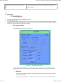
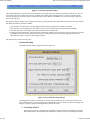
1. The Control Window
The tiptilt control window is shown in Figure 2.1.
Figure 2.1: The Tiptilt control window
This window is used to control the actions of the tiptilt system and also to set some of the more commonly
used parameters associated with the system’s use. The window has three sections, each described below.
1. Menu Bar
At the top of the window is a menu bar with three pull down menus, the Actions menu, the Options
menu and the Help menu.
The Actions menu allows the user to quit the system if necessary. The other two actions allow the
27/08/05 11:30 PM
Tiptilt User Manual
12 of 24
http://www.mso.anu.edu.au/observing/2.3m/tiptilt/tipuser.html
user to save and read in files containing parameter settings. The best policy is to save the current
settings to a file (the default is .tiptilt) and edit this file to effect the desired changes. Note that this
reading and writing of parameter files is optional. All of the parameters may be altered through the
GUI at any time.
The Options menu contains three options, the Show Status Window option, the Show Centroid
Statistics option and the Advanced Settings option. The status window is displayed by default. If the
status window is dismissed, then the first option will redisplay it. The Centroid statistics window is
explained in section 2.1.4 and the Advanced Settings dialogue in section 2.1.5.
The help menu is currently inactive.
2. System State Controls
The next panel in this window is used to both set and display the current system state. By clicking on
the Operate radio button, the tiptilt system will check and initialise the hardware systems, and begin
reading out the CCD in the Acquire mode. By pressing the Idle button, the system is made inactive.
3. System Mode Controls
The System Mode radio buttons are used to select system behaviour whilst in the Operational state.
Recalibrate mode checks the hardware, recalibrates bias and display settings and then automatically
enters the Acquire mode. Recalibrate mode can be used to force an initialisation of the CCD
controller by setting the "Initialise CCD Controller in Recalibrate mode" check box in the advanced
settings dialogue. See section 2.1.5 below.
In the Acquire mode, the entire CCD is continuously read out and displayed in the Ximtool window
to allow a guide object to be positioned on the CCD. There are two areas of the Ximtool window
which are of special importance - the subframe and the acquire frame.
During Acquire mode, the subframe is shown as a yellow box on the Ximtool. The subframe may be
moved by holding down the shift key and clicking the left mouse button on the pixel where the
subframe should be centred. The subframe will now be redisplayed.
The acquire frame is not initially visible, and occupies the entire CCD. It is used in the automatic
acquisition methods on the telescope to find the brightest object. If a crowded field is present on the
CCD and the user wishes to limit the acquisition area to a portion of the CCD, a new acquire frame
may be drawn on the CCD by holding down the left mouse button and dragging to describe the
frame. The image of the acquire frame may be deleted from the Ximtool by using the right mouse
button within the frame area and selecting the destroy option from the menu which appears. Please
note that this removes the acquire frame image from the Ximtool but does not reset the definition of
the acquire frame within the tiptilt system. The acquire frame may be reset by drawing a new frame,
as described above, or by reading a parameter file containing the desired acquire frame dimensions.
Note that drawing an acquire frame when the system is not in acquire mode results in an error. It is
best not to include the edge columns (1 and 64) and rows (1 and 64) in the acquire box as these
sometimes have high counts.
By selecting the Correct radio button the tiptilt system enters the Correct mode. In this mode, the
subframe specified in Acquire mode is read out rapidly. The image is centroided, and the tiptilt
mirror is moved to correct for the difference between the centroid position and the centre of the
subframe. The long term mirror deflection (caused by telescope tracking inaccuracy) is applied to the
telescope system as in an ordinary auto-guider. The subframe is displayed on the Ximtool, but is
shown in the centre of the display, not at its relative position on the CCD; that is, although the image
has moved in the display, the telescope has not moved. When the system returns to Acquire mode,
the mirror is reset to the no-deflection position.
In Guide mode, the system will not correct the centroid using the mirror, but will average the errors
over a 1 second period and transmit the resulting corrections to the telescope system to adjust the
tracking. Telescope corrections are averaged (and not transmitted at the Guide exposure rate) to
"filter" the correction signal and because the telescope tracking will not respond in less than a second.
4. Other Control Window Parameters
The bottom half of the window is devoted to some of the more commonly changed parameters. The first is a
list selection of subframe sizes. Possible values are 8x8, 10x10, 12x12 and 16x16. The default size is 10x10.
For integration times less than 10ms, the 8x8 subframe is required. The selected subframe is displayed on the
Ximtool.
27/08/05 11:30 PM
Tiptilt User Manual
13 of 24
http://www.mso.anu.edu.au/observing/2.3m/tiptilt/tipuser.html
The next three fields control the CCD integration times in milliseconds for the various Operational modes. A
check box next to each field instructs the system to calculate an integration time itself. It does this in Acquire
mode by starting at a minimum integration time of 10 ms and increasing the time by 5 ms until a centroid is
found. In Correct and Guide modes, the integration time is scaled from the peak counts found in Acquire
mode and the Acquisition integration time.
Note that these parameters will not take effect until the Apply button is pressed.
2.
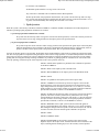
3. The Status Window
The tiptilt status window is shown in Figure 2.2.
27/08/05 11:30 PM
Tiptilt User Manual
14 of 24
http://www.mso.anu.edu.au/observing/2.3m/tiptilt/tipuser.html
Figure 2.2: The Tiptilt status window
This window has three sections: at the top are two strip charts which display the (approximate) instantaneous full width at half
maximum in arcseconds and the peak intensity in ADU counts. The update rate for the two charts may be set in the field
immediately below them.
The next area in this window will display current system warnings and the temperature of the CCD. The warnings which may
appear are:
Cannot Centroid - Operation Suspended: this means that a centroid was found in less than a percentage threshold (default
95%) of the last M images (M is 100 by default). In the Acquire mode this means very little. In Correct or Guide mode, it
means that corrections are not being made. The mirror is left in the last position determined before corrections stopped. The
percentage threshold and the number of frames used are both set in the Advanced Settings dialogue - see section 2.1.5
below.
Saturation Intensity: this means that a frame or frames contained pixels above the saturation threshold (set at 20000 counts).
If this warning is persistent, check that the CCD is still cold (<240K) or try reducing the integration time.
Low Intensity: this means that a frame or frames did not contain enough pixels of sufficient intensity to centroid. See the
Advanced Settings dialogue for more information on setting the low intensity limit.
Temperature out of Range: this warning lights up if the temperature of the CCD drifts more than 15 degrees from the set
point. (the set point is currently 220K but is not adjustable by the user).
The temperature of the CCD is displayed in Kelvin below the warning lights.
The final area in the Status window is a scrolling text area where messages will appear during the course of operation. During
system startup, messages pertaining to the hardware initialisation of the Astromed controller will appear here. Some error messages
will appear here as well, particularly regarding errors in network communications, hardware errors from the tiptilt corrector
assembly and software error conditions. Please note down the messages displayed here in cases of catastrophic failure. In most
cases, shutting down the software and restarting should clear the error.
1. Centroid Statistics
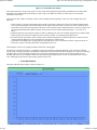
The tiptilt centroid position window is shown in Figure 2.3.
27/08/05 11:30 PM
Tiptilt User Manual
15 of 24
http://www.mso.anu.edu.au/observing/2.3m/tiptilt/tipuser.html
Figure 2.3: The centroid position window
This window displays the position of the current centroid on an XY plot with pixels on the Y axis and time on the X axis. The list
selector at the top of the window allows the user to display the centroid either in absolute pixels or as an error from the current
reference position. The reference position is usually the centre of the subframe. The RMS error over the last second is displayed
near the top of the plot.
The update of the plot window may be paused at any time by pressing the Pause Plot Update button in the lower left of the window;
this makes the following functions available:
Clear Plot Data - this deletes the currently displayed data and starts afresh when the window is unpaused
Save Plot Data - the data displayed in the window may be saved to an ASCII file for later processing and display.
Print Plot - this button will attempt to print the current plot on the default printer.
Scrolling and zooming the Plot - these functions are available by using the mouse in the plot itself. The plot may be zoomed
by dragging on the axis markers in the direction of interest. The plot may then be scrolled by dragging in the plot area.
When the plot window is unpaused, the zooming will reset.
The window may be dismissed at any time.
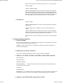
1. Advanced Settings
The tiptilt advanced settings dialogue is shown in Figure 2.4.
Figure 2.4: The advanced settings dialogue
This dialogue allows the user to interactively change system settings. The new value entered will become
active within the tiptilt system when the apply or OK buttons are pressed. If OK is pressed, the dialogue will
disappear; if apply is pressed, the dialogue will remain on the screen.
1. Centroiding Method
The first item is a list box which allows the method by which centroids are calculated to be changed.
The default method is the weighted mean method most commonly used. The sky background is first
27/08/05 11:30 PM
Tiptilt User Manual
16 of 24
http://www.mso.anu.edu.au/observing/2.3m/tiptilt/tipuser.html
calculated by taking a whole frame exposure and finding the mode. The image intensity threshold
specified in the third field is then added to the mode to give a bias level that is subtracted from the
image. The centroid is then calculated as an intensity-weighted pixel position, using only pixels with
positive counts; that is, pixels above the bias level. The subtracted bias is fixed until the operational
mode changes.
The second centroiding option is Adaptive Bias. This method initially calculates the bias as in the
Weighted Mean method, but if too few pixels are available for centroiding the bias is decremented.
Similarly if too many pixels are above the bias, then the bias is incremented. Too few is less than
15% of the pixels being read out, too many is more than 65% of the pixels being read out and the
increment/decrement amount is one count. The actual method used to calculate the centroid is the
Weighted Mean method. This method is useful at dawn and dusk when the (visible) sky level is
changing rapidly. Do not use it in cloudy conditions as, when cloud comes over, the bias level will
drop until the system sees noise, giving excessive mirror movements which will cause tiptilt to drop
into Idle State.
The third centroiding method is a peak centring algorithm. This algorithm finds the brightest pixel in
the frame and computes the marginal distributions about this pixel in each of the X and Y directions.
The distributions are computed for one pixel to each side of the peak pixel, so that a total of three
rows (or columns) are used. A quadratic is then fitted to the distributions in the X and Y directions to
give a centroid with sub-pixel resolution. This method should not be affected by changes in
background sky brightness.
2. Servo Loop Controller Type
The second field determines the closed loop response of the system to movements in the guide image
centroid. In a system such as Tiptilt, where there is a delay between sampling the centroid position
and applying the correction and where the dynamics of the mirror assembly are not perfect, it
becomes necessary to filter the error signal applied to the mirror to avoid instability. The three
available controller types are Fast, Slow and Bright. At present, the Fast controller is the most robust
and best performing under a variety of conditions. The Bright controller requires an integration time
of 20ms or greater.
In principle, this field allows the user to select a filter strategy to suit the seeing conditions. It is
hoped that as the system is used more, better strategies will be made available and guidance on the
conditions appropriate for each strategy will be made available.
3. Image Intensity Threshold
As described in section 2.1.5.1, this field determines the level of the bias subtracted by specifying a
value to add to the sky background.
4. Centroiding Success Fields
The next two fields are used in calculating the Cannot Centroid warning. The No. of frames (M) for
success calculation determines the "memory" of the system. The percentage of frames in the memory
for which a centroid was found is calculated during operation and if this percentage is below the
threshold specified in the next field, mirror movement stops. A warning is also triggered on the status
window. When the percentage of frames with valid centroids has been exceeded, mirror movement
resumes. Note that telescope pointing correction also ceases when this warning is in effect.
5. Initialise CCD Controller in Recalibrate Mode
This check box determines the behaviour of recalibrate mode. Normally, the only time that the CCD controller is initialised is at
system startup or if the CCD temperature changes by more than 5 degrees. You can force the system to initialise the Astromed
controller if you check this box and then enter Recalibrate mode. There should rarely be any need for users to do this.
1.
2. The Telescope Control System
It is possible to control tiptilt by typing in commands at the telescope console, as well as by issuing commands from
the Solaris interface on misty or by running CASPIR do files. The telescope commands are useful mostly for
manually setting track and guide star coordinates, and for initial calibration.
1. Tiptilt Commands
As preparation of the telescope system for future use with any autoguider system, the Tiptilt system is considered a super-guider
which can correct as well as guide. Because of this, two telescope commands have been implemented: GUIDE and TIPTILT.
27/08/05 11:30 PM
Tiptilt User Manual
17 of 24
http://www.mso.anu.edu.au/observing/2.3m/tiptilt/tipuser.html
These commands are equivalent, apart from the state and mode change operations. In this manual only the TIPTILT command will
be explained.
TIPTILT related commands can be split into the following groups:
1. Tiptilt preparation commands:
selecting guide coordinates and setting the Tiptilt reference position.
2. Tiptilt operation commands:
to turn the system on and off etc.
3. Miscellaneous tiptilt commands.
4. Additional qualifiers:
these apply to pre-existing telescope motion commands. They indicate that tiptilt action is to continue after moving the
telescope, using the previously used guide star. For example: TRACK/TIPTILT, OFFSET/TIPTILT.
These commands are now described in detail.
1. Command Reference Guide
1. Tiptilt Preparation
The commands below set the coordinates of the guide star and/or where it will appear on the tiptilt
CCD. When the command is issued, the stage will move and you should see the guide star appear in
the tiptilt subframe.
TIPTILT objectname searches the currently selected coordinate file (refer TRACK/FILE command)
for the supplied object name and sets the coordinates of the selected object as guide coordinates.
TIPTILT/NEXT [n] selects the entry (or the n-th entry) after the current tracking object in the
currently selected coordinate file as guide coordinates; this does not update the index pointer into the
file.
TIPTILT /PREVIOUS [n] selects the entry (or the n-th entry) before the current tracking object in the
currently selected coordinate file as guide coordinates; this does not update the index pointer into the
file.
TIPTILT /TRACK sets the guide coordinates equal to the current tracking coordinates (not the base
coordinates)
TIPTILT /COORDINATES ["name"] RA Dec [equinox[(epoch)]] [Mu_ra Mu_dec [Pi [Vr]]]
[!comment] sets the guide coordinates to the values supplied, any valid coordinate string (refer to the
Telescope User’s Manual) will be accepted. Guide coordinates further than ~2.5 arcminutes from
the tracking coordinate are not accessible as the X-Y stage can not move further.
TIPTILT /OFFSET
By default
accepts guide coordinates as offsets from the current tracking coordinates.
are in arcseconds on the sky.
TIPTILT /OFFSET/BASE
accepts guide coordinates as offsets from the base coordinates.
Base coordinates are the original coordinates specified to the TRACK command, and not including
any subsequent OFFSET commands or telescope movement using the console pushbuttons. By
default
are in arcseconds on the sky.
TIPTILT/OFFSET[/BASE]/RA_TIME
As above, but the RA offset is to be entered in seconds
of time.
TIPTILT/OFFSET[/BASE]/NOSCALE/RA_TIME
scaled by cos
As above, but the RA offset is not to be
to allow use of polar axis rotation offsets, and is to be entered in seconds of time.
The /NOSCALE and /RA_TIME qualifiers may also be used separately.
Any of the above commands can be combined with one only of the following qualifiers:
/REF=(x, y) defines the position on the Tiptilt display on which the guide object is to be centred.
/NOREF {default}?? specifies that the position on the Tiptilt display on which the guide object is to
27/08/05 11:30 PM
Tiptilt User Manual
18 of 24
http://www.mso.anu.edu.au/observing/2.3m/tiptilt/tipuser.html
be centred is to be maintained
/NOSTAGE specifies that the X-Y stage is not to be moved.
Any of the above commands can be combined with the /WAIT qualifier:
/WAIT specifies that, after preparation has been done, the system waits till telescope and X-Y stage
have arrived at the desired positions and then turns the tiptilt system on in the last used mode (correct
or guide). If used immediately after startup, this will select correct mode.
2. Tiptilt Operation
When the system is activated by a TIPTILT, TIPTILT/CORRECT or TIPTILT/GUIDE command, the action taken depends on
whether a preceding Tiptilt preparation command was executed:
a previous preparation command was executed:
the system waits till telescope and X-Y stage have arrived at the desired positions, corrects the reference position for
any inaccuracies in X-Y stage setting and then sets the tiptilt system to the specified mode.
no previous preparation command:
the system accepts the current reference and X-Y stage positions as the position of the guide object in the focal plane
and from that determines the coordinates of the object, assuming that the tracking object is in the currently selected
aperture, and then sets the tiptilt system to the specified mode. This is equivalent to TIPTILT/HERE.
Just prior to entering guide or correct modes, the brightest object found within the acquire frame is assumed to be the desired guide
star. The telescope position is adjusted to bring this object to the reference image position: it is assumed that positional errors result
from incorrect telescope pointing. The effects of differential atmospheric refraction and diffraction are taken into account. During
guiding and correcting, the telescope tracking coordinates stay constant, as guiding signals are considered to be corrections to the
telescope pointing, needed to keep the selected aperture in the correct position on the sky.
TIPTILT without further qualifiers or parameters this command is equivalent
to TIPTILT/CORRECT
TIPTILT /IDLE set the Tiptilt system to the Idle mode
TIPTILT /RECALIBRATE set the Tiptilt system to the Recalibrate mode
TIPTILT /STOP
TIPTILT /ACQUIRE set the Tiptilt system to the Acquire mode
TIPTILT /CORRECT wait till telescope and X-Y stage have arrived at the
desired positions, correct the reference position for any inaccuracies in X-Y
stage setting and then set the tiptilt system to the correct mode (i.e. move the
tiptilt secondary to correct image wander). If no Tiptilt preparation command
preceded this command, it will act as if TIP/HERE was entered.
TIPTILT /GUIDE wait till telescope and X-Y stage have arrived at the desired
positions, correct the reference position for any inaccuracies in X-Y stage
setting and then set the tiptilt system to the guide mode (i.e. drive the telescope
once per second to correct image wander) . If no tiptilt preparation command
preceded this command, it will act as if TIP/HERE was entered.
TIPTILT /RESUME set the Tiptilt system to the last used mode (guide or
correct; if used immediately after startup, will select correct mode), assuming
that nothing has changed since the Tiptilt was last turned off (does not wait for
cessation of motion, does not calculate guide coordinates or aperture).
TIPTILT /FIND
TIPTILT/CORRECT/FIND
TIPTILT/GUIDE/FIND set the reference position to the centroid of the
brightest object in the acquire frame, from that determine the coordinates of the
object, assuming that the tracking object is in the currently selected aperture
27/08/05 11:30 PM
Tiptilt User Manual
19 of 24
http://www.mso.anu.edu.au/observing/2.3m/tiptilt/tipuser.html
and then set the Tiptilt system to the desired mode (correct if not specified).
TIPTILT /HERE
TIPTILT/CORRECT/HERE
TIPTILT/GUIDE/HERE take the current reference and X-Y stage positions
and from those determine the guide coordinates, assuming that the tracking
object is in the currently selected aperture. Then move the brightest object in
the acquire frame to the reference position by autoguiding the telescope, and
then set the Tiptilt system to the desired mode (correct if not specified).
1. Miscellaneous
TIPTILT /SHOW
TIPTILT /SHOW/BRIEF Shows details of tracking and guiding coordinates
and apertures
TIPTILT /SHOW/FULL as /BRIEF, also shows Tiptilt and guider stage
settings.
TIPTILT /PRINT prints the information shown on the screen with /SHOW
(VMS V5.5-2 on MAIA has an unexplained problem with the queue manager
which does not allow any printing, this may be corrected later)
TIPTILT /SAVE saves guide coordinates to the currently selected coordinate
file.
1. Changes to Existing Commands
1. ENLIST/IGNORE
ENLIST TT Starts the processes for communication with Tiptilt. This command needs to be issued
once after telescope startup if tiptilt is to be used.
IGNORE TT Removes the processes for communication with Tiptilt. Issue this command if it is
desired to stop using tiptilt.
2. Modification to all motion commands:
Any motion command (including HALT) issues an implicit TIPTILT/ACQUIRE.
3. Additions to the TRACK, OFFSET, APERTURE and ROTATOR commands:
TRACK/TIPTILT ..........
OFFSET/TIPTILT ..........
APERTURE/TIPTILT........
ROTATOR/TIPTILT ........ When the telescope arrives at the desired position, Tiptilt operation is
resumed with the same guide star.
/NOSTAGE
/NOREFERENCE
/REFERENCE=(x,y) The default behaviour for determining X-Y stage and reference positioning can
be modified by the use of one only of these qualifiers as described for the TIPTILT command.
4. Additions to the CONFIGURE command and to CFILEs
27/08/05 11:30 PM
Tiptilt User Manual
20 of 24
http://www.mso.anu.edu.au/observing/2.3m/tiptilt/tipuser.html
The CFILE command can be used to save and restore the parameters associated with tiptilt operation
(see the 2.3m telescope manual for details of the CFILE command). The addition of the keyword
TIPTILT causes the saving of Tiptilt system configuration variables i.e. to save the tiptilt parameters,
issue the command CFILE /SAVE=TIPTILT[,keywordlist]
Parameters associated with tiptilt operation that can be set with the CONFIGURE command are listed
below (see the 2.3m telescope manual for details of the CONFIGURE command).
SUBFRAME_X_POS
SUBFRAME_Y_POS This pair of integer parameters alters the position of the subframe in pixels on
the tiptilt CCD for use during subsequent Guide or Correct mode operations. The parameters set the
bottom left corner of the subframe.
SUBFRAME_SIZE This parameter alters the subframe size in pixels on the tiptilt CCD for use
during subsequent Guide or Correct mode operations. The size may be set to any of 8x8, 10x10,
12x12 or 16x16.
ACQFRAME_X_SIZE
ACQFRAME_Y_SIZE
ACQFRAME_X_POS
ACQFRAME_Y_POS This group of integer parameters alters the size and position of the acquisition
frame in pixels on the tiptilt CCD for use during subsequent automatic acquisition operations. The
ACQFRAME_X_POS and ACQFRAME_Y_POS parameters set the bottom left corner of the
acquisition frame. The ACQFRAME_X_SIZE and ACQFRAME_Y_SIZE parameters select the
width and height of the acquisition frame. The acquisition frame need not be square, so all parameters
are independent of each other. Omitted parameters remain unchanged.
CENTROID_TYPE This parameter sets the centroiding algorithm used by the system. It may be any
of the following: WEIGHTED_MEAN, ADAPTIVE_BIAS or PEAK. The meaning of these centroid
algorithms is described in section 2.1.5.1.
SERVO_LOOP_TYPE This parameter changes the servo loop controller filter used by the Tiptilt
system. It may be any of FAST, SLOW or BRIGHT. The meaning of these controllers is described in
section 2.1.5.2.
IM_INTENSITY_THRESHOLD
This parameter sets the number of counts added to the sky background when calculating a bias level.
It sets the field described in sections 2.1.5.3.
NUM_SAMPLES
THRESHOLD These two parameters control the centroiding success calculations described in section
2.1.5.4.
ACQ_EXP
CORRECT_EXP
GUIDE_EXP This group of REAL parameters control the exposure times (in milliseconds??) for the
acuter guide and correct modes.
ACQ_EXP_AUTO
CORRECT_EXP_AUTO
GUIDE_EXP_AUTO This group of BOOLEAN parameters control the automatic calculation of
tiptilt exposure times by the system, as described in section 2.1.2.4.
5. Additions to the CALIBRATE command
Before the TipTilt system can be used, the stage position needs to be calibrated. This only needs to be done at the start of an
observing run.
CALIBRATE STAGE
27/08/05 11:30 PM
Tiptilt User Manual
21 of 24
http://www.mso.anu.edu.au/observing/2.3m/tiptilt/tipuser.html
Follow the instructions on the telescope control terminal to set the zero point of the stage motion so that with the stage at 0,0 the
(imaginary) TipTilt CCD pixel 0,0 is aligned with Aperture 0 (the rotator centre) of the telescope system. This procedure assumes
that the current telescope aperture has been properly calibrated using the CALIBRATE APERTURE command.
CALIBRATE STAGE/ADJUST
Especially when using an offset guide star while the science object has to fall on a CASPIR slit, minor calibration errors need to be
rectified. The CALI STAGE/ADJUST procedure allows the stage position to be adjusted with TipTilt running to obtain maximum
throughput through the slit. Follow the instructions on the telescope control terminal. This procedure assumes that the current
telescope aperture and stage position have been properly calibrated, and that the current tracking and guide coordinates are correct.
CALIBRATE TIPTILT/ALL
Inaccuracies in execution of the CALIBRATE APERTURE and CALIBRATE STAGE commands can result in less than optimal
performance of the TipTilt system. To reduce these effects, a combined automated sequence has been developed. CALIBRATE
TIPTILT/ALL requires the observer to only once centre the object on CASPIR. The procedure then rotates the rotator and uses the
TipTilt autoguiding information to determine the telescope aperture, the pointing offsets and the stage zero point, so combining the
usual CALI APERTURE, CALI POINTING, CALI STAGE sequence in one command.
1.
2. Using Tiptilt with CASPIR
1. New Commands
CASPIR/TIPTILT
This command tells CASPIR whether the tiptilt system will be used or not. The current status of this flag is
shown on the CASPIR miscellaneous status screen. The negation, CASPIR/NOTIPTILT, turns the flag off.
If the flag is set, then do files will issue commands to control the tiptilt system according to tiptilt parameters
in the do file. If the flag is not set, then tiptilt parameters in the do file will be ignored and no attempt will be
made to control the tiptilt system when telescope motion commands are encountered. Note that the tiptilt flag
can be set within a do file, temporarily overriding the external setting (see section 2.3.3).
If the flag is set, then the CASPIR observing mode NOD will issue tiptilt commands to place the system in
Acquire mode before each new aperture is selected, and into Correct mode after the telescope has arrived at
each new aperture.
2. Changes to Existing Commands
CASPIR/MODE=NOD
This command still requires the user to define apertures N1 and N2 for the NOD sequence. However, it is no longer necessary to
enter the aperture coordinates into CASPIR. As described above, the TIPTILT flag determines whether the state of the tiptilt
system is changed as the telescope moves between apertures.
CASPIR/STAGE_OFFSET
This command determines whether the system attempts to move the X-Y stage in order to maintain the guide aperture on the tiptilt
CCD when the telescope moves during a do file or in the NOD mode. The current status of this flag is shown on the CASPIR
miscellaneous status screen. The negation, CASPIR/NOSTAGE_OFFSET clears the flag.
If this flag is set and the TIPTILT flag is set then the X-Y stage will move to counter the movement of the telescope in the
following cases:
Nod mode
TRACK_COORD in a do file
GUIDE_COORD in a do file
RA_OFFSET and/or DEC_OFFSET in a do file
GRA_OFFSET and/or GDEC_OFFSET in a do file
If this flag is not set but the TIPTILT flag is set, then in the cases above, the tiptilt system will attempt to move the subframe but
not the X-Y stage to counter the telescope movement.
If the TIPTILT flag is not set, then the STAGE_OFFSET flag is ignored in all cases.
27/08/05 11:30 PM
Tiptilt User Manual
22 of 24
http://www.mso.anu.edu.au/observing/2.3m/tiptilt/tipuser.html
1. New DO File Parameters
TIPTILT/NOTIPTILT
This keyword sets the TIPTILT flag from within a do file. If the NOTIPTILT keyword is encountered, tiptilt parameters are
ignored until the TIPTILT key word is read. If the TIPTILT keyword is encountered, then tiptilt parameters and commands are
executed until a NOTIPTILT keyword is read. This keyword overrides the flag set externally by a CASPIR/[NO]TIPTILT
command. The flag is reset to its original state at the end of the do file.
STAGE_OFFSET/NOSTAGE_OFFSET
This keyword sets the STAGE_OFFSET flag from within a do file. It overrides the flag set externally by a CASPIR/[NO]STAGE
command. The flag is reset to its original state at the end of the do file. The stage will not move if nostage is chosen.
TRACK_COORD
This parameter requires a text string delimited by double quotes and sends a new TRACK/COORD command to the telescope. The
format of the string inside the quotes is the same as that for the telescope command TRACK/COORD, except that no object name
should be present. Instead, the object name should be set using the OBJECT parameter.
At the end of the do file, the telescope remains at the tracking coordinates last set.
Example use:
RUN TRACK_COORD="5 23 42.0 -69 46 00 J2000"
GUIDE_COORD
This parameter requires a text string delimited by double quotes and sends a new TIPTILT/COORD command to the telescope. The
format of the string inside the quotes is the same as that for the telescope command TRACK/COORD, except that no object name
should be present i.e. guide object names are not supported.
At the end of the do file, the guide coordinates remain at the values last set.
GRA_OFFSET and GDEC_OFFSET
These parameters take floating point arguments and issue the equivalent of a TIPTILT/OFFSET/BASE command to the telescope
system. The effect is to set the guide coordinate relative to the telescope base coordinates in arcseconds on the sky. Note that these
parameters do not remain in effect on subsequent lines of a do file. It is the guide coordinate set by them that remains in use.
As a general rule, if a TRACK_COORD command is used on a do file line, either a GUIDE_COORD, or a GRA_OFFSET and a
GDEC_OFFSET, or a TT_FIND command (see below) needs to be specified (unless the same guide star is indeed required).
At the end of the do file, the guide coordinates remain at the values last set.
TTX, TTY, TTDX and TTDY
This group of integer parameters alters the size and position of the subframe in pixels on the tiptilt CCD for use during subsequent
Guide or Correct mode operations. The TTX and TTY parameters set the bottom left corner of the subframe. The TTDX and
TTDY parameters select the width and height of the subframe. It is only necessary to set the X or Y size, as the other axis will be
set to the same value (the tiptilt subframe is always square). If the size parameter is less than or equal to 8 then the subframe size is
set to 8x8. If the size parameter is less than or equal to 10 but greater than 8 then the subframe size is set to 10x10. If the size
parameter is less than or equal to 12 but greater than 10 then the subframe size is set to 12x12. If the size parameter is greater than
12 then the subframe size is set to 16x16. Valid TTX values are 1 to 65-TTDX (although recommended values are 2 to 64-TTDX).
Similarly for TTY.
The new subframe position and size remains in effect after the do file finishes execution.
ACQX, ACQY, ACQDX and ACQDY
27/08/05 11:30 PM
Tiptilt User Manual
23 of 24
http://www.mso.anu.edu.au/observing/2.3m/tiptilt/tipuser.html
This group of integer parameters alters the size and position of the acquisition frame in pixels on the tiptilt CCD for use during
subsequent automatic acquisition operations. The ACQX and ACQY parameters set the bottom left corner of the acquisition frame.
The ACQDX and ACQDY parameters select the width and height of the acquisition frame. The acquisition frame need not be
square, so all parameters are independent of each other. Omitted parameters remain unchanged. Valid values of ACQDX are 1 to
64. ACQX can have values 1 to 65-ACQDX. (Recommended values for ACQDX are 8 to 62 and for ACQX are 63-ACQDX).
Similarly for ACQDY and ACQY.
The new acquisition frame position and size remains in effect after the do file finishes execution.
Note: The top ~20% of the tiptilt CCD (as displayed on misty) is exposed directly to sky. If the sky is bright (as at dawn and dusk,
or in bright moon with cloud), then there will be a significant sky signal here and tiptilt may find the brightest pixel in this region as
the guide star if that pixel is brighter than the brightest pixel at the true guide star position, and provided the top 20% of the CCD is
in the acquire box. To stop this happening, use ACQY=48.
TT_MODE
This text parameter expects one of the following strings which specifies which mode the tiptilt system should be placed in while
data taking is in progress. The string may be GUIDE, RECALIBRATE, CORRECT or ACQUIRE.
If unspecified, the tiptilt system will remain in the Acquire mode. After a TT_MODE parameter has been set, all subsequent do file
runs will use this setting until it is changed.
At the end of a do file, the tiptilt system will be left in the Acquire mode. New do files always default to using Acquire mode.
Example of use:
RUN RA_OFFSET=10 DEC_OFFSET=-5 TT_MODE=CORRECT
TT_FIND/NOTT_FIND
This negatable keyword enables or disables the tiptilt system’s automatic guide star finding feature.
If this keyword is not specified, the tiptilt system will adjust the pointing of the telescope prior to entering Correct or Guide mode
to bring the brightest object in the acquisition frame to the centre of the subframe. If the TT_FIND keyword is set, then prior to
entering Correct or Guide mode, the system will adjust the central position of the subframe to the centre of the brightest object
found in the acquire frame. The telescope pointing will not change and the system will go into correct or guide mode at the current
telescope position. After the TT_FIND or NOTT_FIND keyword has been set, all subsequent do file lines will use this keyword
setting until it is changed. The position of the subframe remains at its adopted position until moved with another TT_FIND or with
TTX, TTY (or at the end of the do file with the GUI or a telescope command).
You should use NOTT_FIND when you know that the guide object you are using has coordinates that are definitely correct and any
misalignment with the tiptilt sensor can be blamed on telescope pointing. You should use TT_FIND if you are not sure about the
presence or suitability of a guide object in the vicinity.
At the end of a do file, the tiptilt system will be left in the NOTT_FIND state. New do files always default to NOTT_FIND.
TT_ERROR/NOTT_ERROR
This negatable keyword determines how CASPIR will handle tiptilt errors if they arise during a do file execution. If
NOTT_ERROR is set, then CASPIR will ignore error codes returned from the tiptilt system and continue on processing the do file.
If TT_ERROR is set, then tiptilt errors will cause the do file to abort processing. Failure to find a suitable guide star is considered
an error. Cloud coming over after a run is successfully started is not considered an error.
If this keyword is not specified, tiptilt errors will be ignored. After the TT_ERROR or NOTT_ERROR keyword has been set, all
subsequent runs in the do file will use this setting until it is changed.
New do files always default to NOTT_ERROR.
TT_ATIME
This floating point parameter sets the Acquire mode integration time in milliseconds. Note that if the "auto" switch for acquire time
is set on the Tiptilt window of the GUI, this parameter is ignored.
The new Acquire mode integration time remains in effect after the do file finishes execution.
TT_GTIME
27/08/05 11:30 PM
Tiptilt User Manual
24 of 24
http://www.mso.anu.edu.au/observing/2.3m/tiptilt/tipuser.html
This floating point parameter sets the Guide mode integration time in milliseconds. Note that if the "auto" switch for guide time is
set on the Tiptilt window of the GUI, this parameter is ignored.
The new Guide mode integration time remains in effect after the do file finishes execution.
TT_CTIME
This floating point parameter sets the Correct mode integration time in milliseconds. Note that if the "auto" switch for correct time
is set on the Tiptilt window of the GUI, this parameter is ignored. The shortest possible integration time is 9.4 ms, which can only
be achieved in a subframe of size 8x8. The minimum integration times for each subframe size is given in the following table:
Subframe size
Minimum tt_ctime(ms)
8x8
9.4
10x10
13.0
12x12
17.2
The following table gives the minimum recommended integration time (ms) as a function of seeing and guide star R magnitude
(since most catalogues give V magnitudes, V-R = 0.5 is a medium value which might be used to derive R from V in the absence of
any other information). The seeing is R-band seeing, an approximate estimate of which is given in the Tiptilt status window when
tiptilt is running. The corresponding K-band seeing, measurable on a CASPIR frame without tiptilt running is given in parentheses.
Note that exposures shorter than 13ms need an 8x8 subframe.
Seeing=1.0 (0.8)
Seeing=1.5 (1.2)
Seeing=2.0 (1.6)
R=10
9.4
9.4
9.4
R=11
9.4
9.4
9.4
R=12
9.4
10
17
R=13
10
25
40
R=14
25
60
100
R=15
60
150
250
The new Correct mode integration time remains in effect after the do file finishes execution.
A convenient web site for obtaining guide stars (HST Guide Star Catalog) is:
http://arch-http.hq.eso.org/cgi-bin/gsc
27/08/05 11:30 PM