1
depth sounder, continue to add them using these same steps. If you have no other devices, move
on to the next step.
Setup the ADCP using the ADCP Configuration Wizard according to USGS standard practice.
Now you’re ready to tryout your ADCP. First, turn the Riverboat power switch on and confirm
that LED 1 on the remote transceiver is green. If it is, choose acquire and start pinging in WinRiver.
The control window will appear, followed by the ADCP wakeup message and you will begin to
hear a quiet pinging noise coming from your ADCP.
Congratulations! Your system is ready to begin making river discharge measurements!
Reference Information
Connections and Wiring
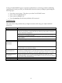
The HydroLink ML2 supports RS 232 with an 8-pin circular Micro-Change connector. The ML2 is
designed to operate as a DTE (Data Terminal Equipment). When connecting to a DCE (Data
Communication Equipment), a straight cable should be used. When connecting to another DTE, a
crossover serial cable must be used. The crossover cable must have TD and RD crossed (pins 2-3
and 3-2).
The Base Transceiver should be connected to the computer. The Remote Transceiver should be
connected to the instruments. Transceivers are provided as a matched pair that communicates only
with each other. Each unit of the pair (set) is programmed with a unique serial number ID.
When using the cables provided by The Oceanscience Group, note that the 8-pin circular connector
is keyed and will not align in any way except in the correct alignment. Once the keyway is
properly aligned, the backshell of the connector should be screwed to finger tightness. This
connector is IP68 rated when properly connected.
The antenna connector is type TNC and care should be given so as to not cross-thread the
connector. Again, finger tight is adequate when threading on the antenna cable.
Power Requirements
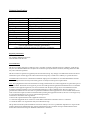
The HydroLink ML series transceiver should be powered from a ‘clean’ DC power source. Input
voltage range must be between 10V and 14V.
Power source should be capable of supplying a peak current of 1.0 Amp.
Power cable to the transceiver should be routed away from the antenna. Close proximity between
the two may result interference.
Transceiver input power is reverse-polarity protected.
9