1
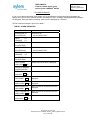
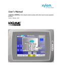
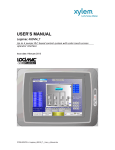
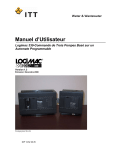
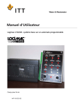
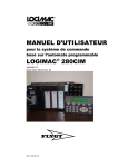
USER’S MNUAL of the PLC-based duplex pump control system LOGIMAC® 280VM Page: 5 of 41 Date June 2012 Replacing: September 2010 . INTRODUCTION The LOGIMAC® 280VM P/N 13-50 90 90 was designed for the control and supervision of a sewage pumping station with one or two pumps. The complete system consists of programmable logic controller LOGIMAC® 280VM-PLC as per the configuration specified in the following chapter, the operator interface LOGIMAC® 280VM-OP and the alarm annunciator LOGIMAC® 280-AP. LOGIMAC® 280-PLC takes an analog level signal 4-20 mA from any of the level sensor with that kind of output. The controller can be used in one of the three programmed mode which is set before shipping: L280 as previous Logimac 280CIM L280CAP with pumps’ capacities calculation L280VFD with VFD control following the level changes Dynamic inflow & pumped volume can be calculated in any of modes. 1.1 Approvals Sensor: CSA certified for operation in Class I, Division 2, Groups C and D hazardous environments. (Note: For this approval to be valid special installation conditions apply). 1.2 Part numbers LOGIMAC® 280VM-PLC (P/N 13-50 90 91 Analog I/O expansion unit (P/N 13-40 02 30) LOGIMAC® 280-AP (P/N 13-50 90 19) LOGIMAC® 280VM-OP (P/N 13-50 90 92) © Copyright 1995 ITT Flygt ® The LOGIMAC is registered mark of ITT Flygt. All rights reserved. No part of this manual may be reproduced or copied without the written permission of ITT Flygt. © Copyright ITT Flygt 2004 FCDN-#95174-V4-LOGIMAC_280VM__USER`S_MANUAL.DOC P/N 13-52 20 36