1
USER’S MNUAL
of the PLC-based duplex pump
control system LOGIMAC® 280VM
Page: 8 of 41
Date June 2012
Replacing: September
2010
.
2.3 ALARM ANNUNCIATOR LOGIMAC® 280-AP
2.3.1 TECHNICAL DATA :
Supply voltage: 24V DC
Current consuming: 80 mA.
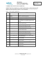
2.3.2 COMPONENTS and THEIR FUNCTIONS:
The annunciator is composed of four (4 ) integrates parts:
•
Printed circuit board (P/N 13-50 90 59)
•
Face plate with descriptions (P/N 13-51 15 34)
•
Board connector with terminal (P/N13-42 00 03)
•
Flat cable (P/N 13-41 00 15)
The printed circuit board
circuit contains:
•
•
•
•
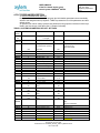
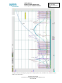
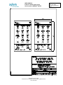
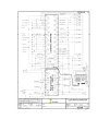
represent the circuit as per drawing 2603-A2 (see appendices 1). The
13 diodes LED ( D1..D13),
2 push buttons (SW1et SW2),
13 resistors (R1..R13) to limit the current and
26 auxiliary diodes of type 1N4004 (D14.. 39).
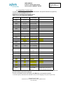
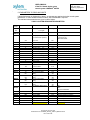
Each parallel circuit (total 16 circuits) is connected to one pin (1-16) of the (P1) plug for the flat cable
.
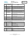
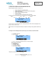
The functions of circuit are :
Indication:
The positive (+) signal of 24V DC power supply connected to terminal 2 is common for all diodes
LED. To turn on the diode LED, the negative (-) signal should be connected to another end of circuit.
It can be done if the PLC output relay contact, connected to the specific LED circuit closes (All PLC
outputs connected to annunciator should have the common terminal COM connected to
negative (-) terminal of source).
Lamp test:
The negative (-) signal of 24V DC power supply connected to terminal 1 is used to test LED diodes.
Pushing the push button SW1, connects 24V DC power supply to all LED diode circuits and turn all
LED’s on.
Acknowledge/Reset:
By pressing the push button SW2, the positive (+) signal of 24V DC power supply will be connected
to PLC input being connected to terminal 4 of the annunciator.
This input signal is programmed in PLC as acknowledge signal ( first appearance) and as reset
signal (second appearance).
It is important to connect the common terminal COM of this PLC input to negative ( - )
terminal of source.
© Copyright ITT Flygt 2004
FCDN-#95174-V4-LOGIMAC_280VM__USER`S_MANUAL.DOC
P/N 13-52 20 36