1
User’s Guide
Publication Number E2454-97005
June 2000
For Safety Information, Warranties, and Regulatory Information, see the
pages at the end of this manual.
Copyright Agilent Technologies 1994-2000
All Rights Reserved.
Agilent Technologies E2454A
Analysis Probe for Intel
80386EX
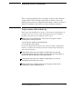
The Agilent Technologies E2454A Analysis
Probe — At a Glance
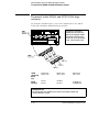
The Agilent Technologies E2454A Analysis Probe provides a
complete interface for state or timing analysis between any of the
supported 80386 microprocessors listed below and Agilent
Technologies logic analyzers. The supported logic analyzers are listed
in chapter 1.
Supported Microprocessors
Microprocessor
Package
Ordering Information
80386EX
132-pin QFP
E2454A
80386EX
144-pin TQFP
E2454A and E5336A
The analysis probe provides the physical connection between the
target microprocessor and the logic analyzer. The configuration
software on the enclosed disks set up the logic analyzer for
compatibility with the analysis probe. The inverse assemblers on the
disks provide displays of the 80386 data bus in 80386 assembly
language mnemonics.
If you are using the analysis probe with the Agilent Technologies
16600 or 16700 series logic analysis systems, you only need this
manual as a reference. The Agilent Technologies 16600 and 16700
series contain a Setup Assistant, which guides you through the
connection and configuration process using on-screen dialog
windows. For an overview of Setup Assistant, refer to Chapter 1,
"Setup Assistant."
For more information on the logic analyzers or microprocessor, refer
to the appropriate reference manuals for those products.
ii
E2454A 80386EX Analysis Probe
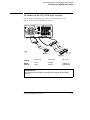
The Agilent Technologies E2454A Analysis Probe — At a Glance
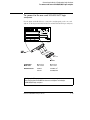
Analyzing a Target System with the Agilent Technologies E2454A Analysis Probe
E2454A 80386EX Analysis Probe
iii
In This Book
This book is the User’s Guide for the Agilent Technologies E2454A Analysis
Probe. It assumes that you have a working knowledge of the logic analyzer
used and the microprocessor being analyzed.
This user’s guide is organized into the following chapters:
Chapter 1 contains overview information, including a list of required
equipment.
Overview
Chapter 1
Chapter 2 explains how to connect the logic analyzer to your target
system through the analysis probe, and how to configure the analysis
probe and logic analyzer to interpret target system activity. The last
section in this chapter shows you how to hook up optional equipment
to obtain additional functionality.
Connecting &
Configuring
Your System
Chapter 2
Connecting
the Analysis
Probe to the
Target System
Agilent Technologies 16600 and 16700 Series Logic Analysis Systems
Connecting
the Analysis
Probe to the
Logic Analyzer
If you are using the analysis probe with Agilent Technologies 16600 or 16700
series logic analysis systems, you only need this manual as a reference for
obtaining and interpreting data. The Agilent Technologies 16600 and 16700
contain a Setup Assistant, which guides you through the connection and
configuration process using on-screen dialog windows. For an overview of
Setup Assistant, refer to chapter 1, "Setup Assistant."
Configuring
Connecting
Optional
Equipment
Analyzing the
Target System
Chapter 3
Chapter 3 provides information on analyzing the supported
microprocessors.
Reference
Chapter 4
Chapter 4 contains reference information on the analysis probe.
If You Have
a Problem
Chapter 5
Chapter 5 contains troubleshooting information.
iv
E2454A 80386EX Analysis Probe
Contents
The Agilent Technologies E2454A Analysis Probe — At a Glance –ii
1 Overview
Setup Assistant 1–3
Logic Analyzers Supported 1–4
Logic analyzer software version requirements 1–6
Equipment Used with the Analysis Probe 1–7
Equipment supplied 1–7
Agilent Technologies E2454A 1–7
Agilent Technologies E2454A and E5336A 1–7
Minimum equipment required 1–9
Additional equipment supported 1–9
2 Connecting and Configuring Your System
Power-on/Power-off Sequence 2–4
To power on 16600 and 16700 series logic analysis systems 2–4
To power on all other logic analyzers 2–4
To power off 2–4
Connecting the Analysis Probe to the Target System 2–5
To connect to a 132-pin QFP target system 2–6
Removing the Probe Adapter 2–8
To connect to a 144-pin TQFP target system 2–9
Connecting the Analysis Probe to the Logic Analyzer 2–12
Analysis probe pod locations 2–13
To connect to the 16600A logic analysis system 2–14
Contents-1
Contents
To connect to the 16601A logic analysis system 2–15
To connect to the 16602A logic analysis system 2–16
To connect to the 16603A logic analyzer 2–17
To connect to the 16550A, and 16710/11/12A logic analyzers 2–18
To connect to the one-card 16554/55/56/57 logic analyzers 2–19
To connect to the two-card 16554/55/56/57 logic analyzers 2–20
To connect to the 1660A/AS/C/CS/CP/E/ES/EP logic analyzers 2–21
To connect to the 1661A/AS/C/CS/CP/E/ES/EP logic analyzers 2–22
To connect to the 1662A/AS/C/CS/CP/E/ES/EP logic analyzers 2–23
To connect to the 1670A/D/E logic analyzer 2–24
To connect to the 1671A/D/E logic analyzer 2–25
To connect to the 1672A/D/E logic analyzer 2–26
Configuring 2–27
Configuring the Analysis Probe 2–28
To set the State/Timing jumper 2–28
Configuring the Logic Analysis System 2–29
To load configuration and inverse assembler files — 16600/700 logic analysis
systems 2–30
To load configuration and inverse assembler files — other logic analyzers 2–
31
Connecting Optional Equipment 2–33
3 Analyzing the Target System
Modes of Operation 3–3
State-per-transfer mode 3–3
State-per-clock mode 3–3
Timing mode 3–4
Logic Analyzer Configuration 3–5
Trigger specification 3–5
Contents-2
Contents
Format specification 3–5
Status Encoding 3–7
Logic Analyzer Symbols 3–8
To display the timing format specification 3–10
To display captured timing data 3–11
Using the Inverse Assemblers 3–12
Listing menu 3–13
To align the inverse assemblers 3–15
Inverse assembler output format 3–17
Default Size (Code) 3–17
Logical Address Display 3–17
Numeric Format
3–18
Multiple Instructions In a Single Fetch 3–18
Multiple-Byte Instructions 3–18
Missing Opcodes 3–18
Don’t Care Bytes 3–18
Unexecuted Prefetched Instructions 3–19
Prefetch Triggering 3–19
Inverse assembler error messages 3–20
The I386EXE inverse assembler 3–21
Load 3–21
Filter 3–21
Contents-3
Contents
IDT Description 3–23
Align 3–23
Options 3–23
4 Reference
Operating characteristics 4–3
Theory of operation and clocking 4–4
Timing Mode 4–6
Signal-to-connector mapping 4–6
Circuit board dimensions 4–16
Replaceable parts 4–17
5 If You Have a Problem
Analyzer Problems 5–3
Intermittent data errors 5–3
Unwanted triggers 5–3
No activity on activity indicators 5–4
No trace list display 5–4
Analyzer won’t power up 5–4
Analysis Probe Problems 5–5
Target system will not boot up 5–5
Erratic trace measurements 5–6
Capacitive loading 5–6
Inverse Assembler Problems 5–7
No inverse assembly or incorrect inverse assembly 5–7
Inverse assembler will not load or run 5–8
Intermodule Measurement Problems 5–9
An event wasn’t captured by one of the modules 5–9
Contents-4
Contents
Analyzer Messages 5–10
“. . . Enhanced Inverse Assembler Not Found” 5–10
“. . . Inverse Assembler Not Found” 5–10
“. . . Does Not Appear to be an Inverse Assembler File” 5–10
“Measurement Initialization Error” 5–11
“No Configuration File Loaded” 5–14
“Selected File is Incompatible” 5–14
“Slow or Missing Clock” 5–14
“Time from Arm Greater Than 41.93 ms” 5–15
“Waiting for Trigger” 5–15
Cleaning the Instrument 5–16
Glossary
Contents-5
Contents
Contents-6
1
Overview
Overview
This chapter describes:
Overview
Chapter 1
Connecting &
Configuring
Your System
Chapter 2
•
•
•
•
•
•
•
Setup Assistant
Logic analyzers supported
Logic analyzer software version requirements
Equipment used with the analysis probe
Equipment supplied
Minimum equipment required
Additional equipment supported
Connecting
the Analysis
Probe to the
Target System
Connecting
the Analysis
Probe to the
Logic Analyzer
Configuring
Connecting
Optional
Equipment
Analyzing the
Target System
Chapter 3
Reference
Chapter 4
If You Have
a Problem
Chapter 5
1-2
E2454A 80386EX Analysis Probe
Setup Assistant
Setup Assistant is an online tool for connecting and configuring your
logic analysis system for microprocessor and bus analysis. Setup
Assistant is available on the Agilent Technologies 16600 and 16700
series logic analysis systems. You can use Setup Assistant in place of
the connection and configuration procedures provided in chapter 2.
This menu-driven tool will guide you through the connection
procedures for connecting the logic analyzer to an analysis probe, an
emulation module, or other supported equipment. It will also guide
you through connecting an analysis probe to the target system.
Access Setup Assistant by clicking its icon in the Logic Analysis
System window. The on-screen dialog prompts you to choose the
type of measurements you want to make, the type of target system,
and the associated products that you want to set up.
If you ordered this product with your Agilent Technologies 16600/700
logic analysis system, the logic analysis system has the latest software
installed, including support for this product. If you received this
product after you received your logic analysis system, this product
might not be listed under supported products. In that case, you need
to install the I80386 Processor Support Package. Use the procedure
on the CD-ROM jacket to install the I80386 Processor Support
Package.
E2454A 80386EX Analysis Probe
1-3
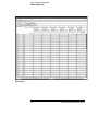
Logic Analyzers Supported
The table below lists the logic analyzers supported by the Agilent
Technologies E2454A analysis probe. Logic analyzer software version
requirements are shown on the following page.
The Agilent Technologies E2454A requires four logic analyzer pods
(68 channels) for inverse assembly. The analysis probe contains two
additional pods that you can monitor.
1-4
E2454A 80386EX Analysis Probe
Logic Analyzers Supported
Logic Analyzers Supported
Logic Analyzer
Channel
Count
State
Speed
Timing
Speed
Memory
Depth
16710A (1 card)
102/card
100 MHz
250 MHz
8 k states
16711A (1 card)
102/card
100 MHz
250 MHz
32 k states
16712A (1 card)
102/card
100 MHz
250 MHz
128 k states
16600A
204
100 MHz
125 MHz
64 k states
16601A
136
100 MHz
125 MHz
64 k states
16602A
102
100 MHz
125 MHz
64 k states
16603A
68
100 MHz
125 MHz
64 k states
16550A (1 card)
102/card
100 MHz
250 MHz
4 k states
16554A (1 or 2 cards)
68/card
70 MHz
125 MHz
512 k states
16555A (1 or 2 cards)
68/card
110 MHz
250 MHz
1 M states
16555D (1 or 2 cards)
68/card
110 MHz
250 MHz
2 M states
16556A (1 or 2 cards)
68/card
100 MHz
200 MHz
1 M states
16556D (1 or 2 cards)
68/card
100 MHz
200 MHz
2 M states
16557D (1 or 2 cards)
68/card
135 MHz
250 MHz
2 M states
1660A/AS/C/CS/CP/E/ES/EP
136
100 MHz
250 MHz
4 k states
1661A/AS/C/CS/CP/E/ES/EP
102
100 MHz
250 MHz
4 k states
1662A/AS/C/CS/CP/E/ES/EP
68
100 MHz
250 MHz
4 k states
1670A
136
70 MHz
125 MHz
64 k or .5 M states
1670D
136
100 MHz
125 MHz
64 k or 1 M states
1671A
102
70 MHz
125 MHz
64 k or .5 M
1671D
102
100 MHz
125 MHz
64 k or 1 M
1672A
68
70 MHz
125 MHz
64 k or .5 M
1672D
68
100 MHz
125 MHz
64 k or 1 M
1670E/71E/72E
68
100 MHz
125 MHz
1M states
E2454A 80386EX Analysis Probe
1-5
Logic Analyzers Supported
Logic analyzer software version requirements
Logic analyzer software version requirements
The logic analyzers must have software with a version number greater than
or equal to those listed below to make a measurement with the Agilent
Technologies E2454A. You can obtain the latest software at the following web
site:
www.agilent.com/find/logicanalyzer
If your software version is older than those listed, load new system software
with the above version numbers or higher before loading the Agilent
Technologies E2454A software.
Logic Analyzer Software Version Requirements
Agilent Technologies
Logic Analyzer
Minimum Logic Analyzer Software Version for use with
Agilent Technologies E2454A
16600 Series
The latest Agilent Technologies 16600 logic analyzer software
version is on the CD-ROM shipped with this product.
1660A/AS Series
A.03.01
1660C/CS/CP Series
A.02.01
1660E/ES/EP Series
A.02.01
1670A/D Series
A.02.01
1670E Series
A.02.01
Agilent Technologies
Mainframes*
16700 Series
The latest Agilent Technologies 16700 logic analyzer software
version is on the CD-ROM shipped with this product.
16500C Mainframe
A.01.05
16500B Mainframe
A.03.14
* The mainframes are used with the Agilent Technologies 16550 and Agilent Technologies 16554/55/56/57 logic
analyzer modules.
1-6
E2454A 80386EX Analysis Probe
Equipment Used with the Analysis Probe
This section lists equipment used with the analysis probe. This
information is organized under the following titles: equipment
supplied, minimum equipment required, and additional equipment
supported
Equipment supplied
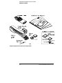
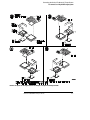
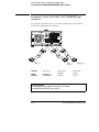
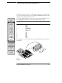
The equipment supplied with the analysis probe is shown in the illustration
on the next page. It is listed below:
Agilent Technologies E2454A
•
•
•
•
•
The analysis probe circuit card.
Three double-density logic analyzer cables.
Two jumpers.
T10 Torx screwdriver.
The Agilent Technologies E3417A 132-pin QFP Probe Adapter, which
includes a probe adapter cable, CQFP-to-PQFP adapters, an extraction
tool for removing the probe adapter from the target system, and an
Operating Note
• Logic analyzer configuration files and inverse assembler software on a
3.5-inch disk.
• Logic analyzer configuration files and inverse assembler software on a
CD-ROM.
• This User’s Guide.
Agilent Technologies E2454A and E5336A
If you ordered the Agilent Technologies E5336A Elastomeric Probing System,
you also received a probe adapter, a general-purpose flexible adapter, and an
Installation Guide.
E2454A 80386EX Analysis Probe
1-7
Equipment Used with the Analysis Probe
Equipment supplied
Equipment Supplied with the Agilent Technologies E2454A
1-8
E2454A 80386EX Analysis Probe
Equipment Used with the Analysis Probe
Minimum equipment required
Minimum equipment required
For state and timing analysis of an 80386 target system, you need all of the
following items.
• The Agilent Technologies E2454A Analysis Probe.
• For 144-pin TQFP target systems, the Agilent Technologies E5336A
Elastomeric Probing System.
• Sufficient area around the target system microprocessor (keep-out area)
for the probe adapter. The keep-out areas are shown in the probe adapter
installation guides.
• One of the logic analyzers listed on page 1-4. The logic analyzer software
version requirements are listed on page 1-5.
Additional equipment supported
The Agilent Technologies E2454A does not support any additional equipment.
E2454A 80386EX Analysis Probe
1-9
1-10
E2454A 80386EX Analysis Probe
2
Connecting and Configuring
Your System
Connecting and Configuring Your System
This chapter shows you how to connect the logic analyzer to the
target system through the analysis probe.
Overview
Chapter 1
Connecting &
Configuring
Your System
Chapter 2
Connecting
the Analysis
Probe to the
Target System
Connecting
the Analysis
Probe to the
Logic Analyzer
Configuring
Connecting
Optional
Equipment
If you are connecting to an Agilent Technologies 16600 or 16700
series logic analysis system, follow the instructions given on-screen in
the Setup Assistant for connecting and configuring your system. Use
this manual for additional information, if desired. Refer to chapter 1
for a description of Setup Assistant.
If you are not using the Setup Assistant, follow the instructions given
in this chapter. This chapter is divided into the following sections;
the order shown here is the recommended order for performing these
tasks:
•
•
•
•
•
•
Read the power on/power off sequence
Connect the analysis probe to the target system
Connect the analysis probe to the logic analyzer
Configure the analysis probe
Configure the logic analyzer
Connect optional equipment
Analyzing the
Target System
Chapter 3
Reference
Chapter 4
If You Have
a Problem
Chapter 5
2–2
E2454A 80386EX Analysis Probe
Connection Sequence
E2454A 80386EX Analysis Probe
2–3
Power-on/Power-off Sequence
Listed below are the sequences for powering on and off a fully
connected system. Simply stated, your target system is always the
last to be powered on, and the first to be powered off.
To power on 16600 and 16700 series logic analysis
systems
Ensure the target system is powered off.
1 Turn on the logic analyzer. The Setup Assistant will guide you
through the process of connecting and configuring the analysis probe.
2 When the analysis probe is connected to the target system and logic
analyzer, and everything is configured, turn on your target system.
To power on all other logic analyzers
With all components connected, power on your system in the following order:
1 Logic analysis system.
2 Your target system.
To power off
Turn off power to your system in the following order:
1 Turn off your target system.
2 Turn off your logic analysis system.
2–4
E2454A 80386EX Analysis Probe
Connecting the Analysis Probe to the Target
System
Overview
Chapter 1
Connecting &
Configuring
Your System
Chapter 2
Connecting
the Analysis
Probe to the
Target System
Connecting
the Analysis
Probe to the
Logic Analyzer
Configuring
Connecting
Optional
Equipment
Analyzing the
Target System
Chapter 3
This section explains how to connect the Agilent Technologies
E2454A Analysis Probe to the target system. Connecting the analysis
probe to the target system consists of the following tasks:
• Connect the probe adapter to the target system.
For QFP target systems, refer to "To connect to a 132-pin QFP target
system."
For TQFP target systems, refer to "To connect to a 144-pin TQFP
target system."
• Connect the analysis probe to the probe adapter.
The remainder of this section describes these general tasks in more
detail.
Protect Your Equipment
The analysis probe socket assembly pins are covered for shipment with a
conductive foam wafer or conductive plastic pin protector. This protects the
delicate gold-plated pins from damage due to impact. When you are not using
the analysis probe, protect the socket assembly pins by covering them with the
pin protector.
Reference
Chapter 4
If You Have
a Problem
Chapter 5
E2454A 80386EX Analysis Probe
2–5
Connecting the Analysis Probe to the Target System
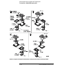
To connect to a 132-pin QFP target system
To connect to a 132-pin QFP target system
The Agilent Technologies 3417A QFP Probe Adapter provides a connection
between the analysis probe and the 132-pin 80386 QFP microprocessor. The
probe adapter attaches over the microprocessor. The analysis probe PGA
socket connects directly to the probe adapter. The E3417A consists of the
following:
•
•
•
•
Probe Adapter Cable
CQFP-to-PQFP Adapters
Extraction tool, for removing the probe adapter from the target system
An Operating Note
The keep-out area showing the required clearances for the PQFP adapter are
in the QFP Probe Adapter Operating Note.
Use the following procedure to install the QFP Probe Adapter.
CAUTION
Equipment Damage. To prevent equipment damage, remove power from
the target system and make sure no logic analyzer cables are connected to
the analysis probe.
1 Turn off the target system and logic analyzer.
2 Select the rotation (shown on the next page) that best suits your
target system. Note the following indicators on the illustration:
• position of Pin 1 on the microprocessor
• color/bar code on both ends of the flexible adapter
• position of Pin A1 on the analysis probe
You can install the flexible adapter in one of four rotations as shown in the
following illustration. This allows flexibility in attaching the analysis probe
when target system components interfere.
3 Refer to the QFP probe adapter Operating Note for specific
instructions to connect the probe adapter to the target system.
4 Attach the Agilent Technologies E2454A analysis probe to the probe
adapter using the rotation selected in step 2.
2–6
E2454A 80386EX Analysis Probe
Connecting the Analysis Probe to the Target System
To connect to a 132-pin QFP target system
Rotations for Agilent Technologies E3417A Probe Adapter and Agilent Technologies E2454A
E2454A 80386EX Analysis Probe
2–7
Connecting the Analysis Probe to the Target System
To connect to a 132-pin QFP target system
Removing the Probe Adapter
CAUTION
Damage to the probe adapter. Use the extractor tool provided (Agilent
part number E3435-03801) and follow the removal instructions below.
Improper removal will result in broken combs in your probe adapter.
The QFP Probe Adapter Assembly is carefully designed in a robust
mechanical package to make reliable electrical contact to each lead of your
target IC. Installing and removing the probe requires you to overcome
cumulative friction between 132 target leads and corresponding parts of the
probe. Removing the probe requires greater force due to the triangular
cross-section of the plastic comb teeth that fit between target leads and align
the probe contacts. Tests show little risk of probe damage in installing the
probe. However, removing the probe by hand from a target with very little
space between leads has resulted in broken combs. A simple tool is provided
with your QFP Probe Adapter to reduce the risk of such damage. Use the
following steps for removal:
1 Place the extractor tool in one of six indentations on the side of the
probe adapter next to the PC board as shown below.
2 Gently pry the probe approximately 1/16 inch (1.588 mm) by
leveraging against the PC board.
3 Repeat this process on all four sides of the probe adapter until the
probe adapter is free from the target system.
Removing the 132-pin QFP Probe Adapter
2–8
E2454A 80386EX Analysis Probe
Connecting the Analysis Probe to the Target System
To connect to a 144-pin TQFP target system
To connect to a 144-pin TQFP target system
The Agilent Technologies E5336A Elastomeric Probing System attaches to a
144-pin TQFP microprocessor, and provides a PGA socket for attaching the
Agilent Technologies E2454A Analysis Probe. The Agilent Technologies
E5336A consists of the following:
• Elastomeric Probe Adapter, which includes an Installation Guide
• General-Purpose Flexible Adapter
CAUTION
Equipment Damage. To prevent equipment damage, remove power from
the target system and make sure no logic analyzer cables are connected to
the analysis probe.
1 Turn off the target system and disconnect all logic analyzer cables
from the analysis probe.
2 Select the rotation (shown on the next page) that best suits your
target system. Note the following indicators on the illustration:
•
•
•
•
•
•
Position of Pin 1 on the microprocessor
Position of little pin on the retainer
Position of little hole on the probe adapter
Color code on both ends of the flexible adapter (see illustration)
Position of indicator on the transition socket
Position of Pin A1 on the analysis probe
Flexible adapters can be installed in one of four rotations as shown in the
illustration. This allows flexibility in attaching the analysis probe when target
system components interfere.
CAUTION
Serious damage can be done to the target system or analysis probe from
incorrect connection. Note the position of pin 1 on the target system and
Pin A1 on the analysis probe prior to making any connection. Also, take
care to align the pins so that all pins are making contact.
3 Follow the instructions in the probe adapter Installation Guide to adhere the
retainer and attach the probe adapter to the microprocessor.
E2454A 80386EX Analysis Probe
2–9
Connecting the Analysis Probe to the Target System
To connect to a 144-pin TQFP target system
Rotations for Agilent Technologies E5336A Elastomeric Probing System and Agilent Technologies E2454A
2–10
E2454A 80386EX Analysis Probe
Connecting the Analysis Probe to the Target System
To connect to a 144-pin TQFP target system
4 Using the rotation selected in step 2 and the illustration on the
previous page, attach the flexible adapter to the probe adapter.
5 Using the rotation selected in step 2 and the illustration on the
previous page, attach the PGA socket on the analysis probe to the
flexible adapter.
CAUTION
Serious Equipment Damage
Ensure that the analysis probe, pin adapters, transition board, flexible
adapter, and probe adapter are aligned and seated correctly in the sockets.
Serious equipment damage can result from incorrect connection. The final
connection must match the rotation selected from the previous page.
E2454A 80386EX Analysis Probe
2–11
Connecting the Analysis Probe to the Logic
Analyzer
Overview
Chapter 1
Connecting &
Configuring
Your System
Chapter 2
Connecting
the Analysis
Probe to the
Target System
Connecting
the Analysis
Probe to the
Logic Analyzer
Configuring
Connecting
Optional
Equipment
Analyzing the
Target System
Chapter 3
Reference
Chapter 4
If You Have
a Problem
Chapter 5
The following sections show the connections between the logic
analyzer pod cables and the analysis probe cables. Use the
appropriate section for your logic analyzer. The configuration file
names for each logic analyzer are located at the bottom of the
connection diagrams.
A minimum of four analysis analysis pods are required for inverse
assembly (P1, P2, P3, and P4). These are located on two
high-density connectors on the Agilent Technologies E2454A (J4 and
J5). P5 and P6 contain additional status signals which may be useful
for microprocessor analysis. The analysis probe connectors are shown
on the following page.
This section shows connection diagrams for connecting the analysis
probe to the Agilent Technologies logic analyzers listed below:
•
•
•
•
•
•
•
•
•
•
•
•
16600A logic analysis system
16601A logic analysis system
16602A logic analysis system
16603A logic analysis system
16550A logic analyzers (one card)
16554/55/56 logic analyzers (one or two cards)
1660A/AS/C/CS/CP logic analyzers
1661A/AS/C/CS/CP logic analyzers
1662A/AS/C/CS/CP logic analyzers
1670A/D logic analyzers
1671A/D logic analyzers
1672A/D logic analyzers
2–12
E2454A 80386EX Analysis Probe
Connecting the Analysis Probe to the Logic Analyzer
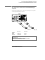
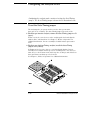
Analysis probe pod locations
Analysis probe pod locations
The illustration below shows the pod locations on the analysis probe.
The Agilent Technologies E2454A connectors require the double-density
logic analyzer cables. Use the procedure in the logic analyzer Service Guide
to remove the logic analyzer cables and replace them with the double-density
cables.
Agilent Technologies E2454A Analysis Probe Pod Locations
E2454A 80386EX Analysis Probe
2–13
Connecting the Analysis Probe to the Logic Analyzer
To connect to the 16600A logic analysis system
To connect to the 16600A logic analysis system
Use the figure and table below to connect the analysis probe to the Agilent
Technologies 16600A logic analysis system.
16600
Pods 7 thru 11
Pods 5 and 6
Pods 3 and 4
Pods 1 and 2
E2454A Connector
not used
P5 misc
P6 misc
P3 DATA
P4 STAT
P1 ADDR clk ↑
P2 ADDR/STAT
Configuration File
Use configuration file P386EX4 for the Agilent Technologies 16600 logic analyzer.
2–14
E2454A 80386EX Analysis Probe
Connecting the Analysis Probe to the Logic Analyzer
To connect to the 16601A logic analysis system
To connect to the 16601A logic analysis system
Use the figure and table below to connect the analysis probe to the Agilent
Technologies 16601A logic analysis system.
16601
Pods 7 and 8
Pods 5 and 6
Pods 3 and 4
Pods 1 and 2
E2454A Connector
not used
P5 misc
P6 misc
P3 DATA
P4 STAT
P1 ADDR clk ↑
P2 ADDR/STAT
Configuration File
Use configuration file P386EX4 for the Agilent Technologies 16601 logic analyzer.
E2454A 80386EX Analysis Probe
2–15
Connecting the Analysis Probe to the Logic Analyzer
To connect to the 16602A logic analysis system
To connect to the 16602A logic analysis system
Use the figure and table below to connect the analysis probe to the Agilent
Technologies 16602A logic analysis system.
16602
Pods 5 and 6
Pods 3 and 4
Pods 1 and 2
E2454A
Connector
P5 misc
P6 misc
P3 DATA
P4 STAT
P1 ADDR clk ↑
P2 ADDR/STAT
Configuration File
Use configuration file P386EX4 for the Agilent Technologies 16602 logic analyzer.
2–16
E2454A 80386EX Analysis Probe
Connecting the Analysis Probe to the Logic Analyzer
To connect to the 16603A logic analyzer
To connect to the 16603A logic analyzer
Use the figure and table below to connect the analysis probe to the Agilent
Technologies 16603A logic analyzer.
16603
Pods 3 and 4
Pods 1 and 2
E2454A
Connector
P3 DATA
P4 STAT
P1 ADDR clk ↑
P2 ADDR/STAT
Configuration File
Use configuration file P386EX5 for the Agilent Technologies 16603 logic analyzer.
E2454A 80386EX Analysis Probe
2–17
Connecting the Analysis Probe to the Logic Analyzer
To connect to the 16550A, and 16710/11/12A logic analyzers
To connect to the 16550A, and 16710/11/12A logic
analyzers
Use the figure and table below to connect the analysis probe to the Agilent
Technologies 16550A or 16710/11/12A logic analyzer.
The Agilent Technologies
E2454A does not require the
Agilent Technologies 16550A
and 16710/11/12A Expansion
Card. If you are using multiple
cards, use the Master Card.
16550A
16710/11/12A
Master
Card
Master Card
Pods 5 and 6
Master Card
Pods 3 and 4
Master Card
Pods 1 and 2
E2454A
Connector
P5 misc
P6 misc
P3 DATA
P4 STAT
P1 ADDR clk ↑
P2 ADDR/STAT
Configuration File
Use configuration file P386EX1 for the Agilent Technologies 16550A and
16710/11/12A logic analyzer.
2–18
E2454A 80386EX Analysis Probe
Connecting the Analysis Probe to the Logic Analyzer
To connect to the one-card 16554/55/56/57 logic analyzers
To connect to the one-card 16554/55/56/57 logic
analyzers
Use the figure and table below to connect the analysis probe to the one-card
Agilent Technologies 16554A/55A/56/57A and 16555D/56/57D logic analyzers.
16554/55/56/57
Master Card
Master Card
Pods 3 and 4
Master Card
Pods 1 and 2
E2454A Connector
P3 DATA
P4 STAT
P1 ADDR clk ↑
P2 ADDR/STAT
Configuration File
Use configuration file P386EX5 for the one-card Agilent Technologies
16554/55/56/57 logic analyzers.
E2454A 80386EX Analysis Probe
2–19
Connecting the Analysis Probe to the Logic Analyzer
To connect to the two-card 16554/55/56/57 logic analyzers
To connect to the two-card 16554/55/56/57 logic
analyzers
Use the figure and table below to connect the analysis probe to the two-card
Agilent Technologies 16554A/55A/56A and 16555D/56D/57D logic analyzers.
16554/55/56/57
Exp. Card 1
Expansion Card 1
Pods 3 and 4
Expansion Card 1
Pods 1 and 2
E2454A Connector
not used
P5 misc, P6 misc
16554/55/56/57
Master Card
Master Card
Pods 3 and 4
Master Card
Pods 1 and 2
E2454A Connector
P3 DATA, P4 STAT
P1 ADDR clk ↑,
P2 ADDR/STAT
Configuration File
Use configuration file P386EX4 for the two-card Agilent Technologies
16554/55/56/57 logic analyzers.
2–20
E2454A 80386EX Analysis Probe
Connecting the Analysis Probe to the Logic Analyzer
To connect to the 1660A/AS/C/CS/CP/E/ES/EP logic analyzers
To connect to the 1660A/AS/C/CS/CP/E/ES/EP logic
analyzers
Use the figure and table below to connect the analysis probe to the Agilent
Technologies 1660A/C/E logic analyzers.
1660A/C/E
Pods 1 and 2
Pods 3 and 4
Pods 5 and 6
Pods 7 and 8
E2454A
Connector
P1 ADDR clk ↑
P2 ADDR/STAT
P3 DATA
P4 STAT
P5 misc
P6 misc
not used
Configuration File
Use configuration file P386EX3 for the Agilent Technologies
1660A/AS/C/CS/CP/E/ES/EP logic analyzers.
E2454A 80386EX Analysis Probe
2–21
Connecting the Analysis Probe to the Logic Analyzer
To connect to the 1661A/AS/C/CS/CP/E/ES/EP logic analyzers
To connect to the 1661A/AS/C/CS/CP/E/ES/EP logic
analyzers
Use the figure and table below to connect the analysis probe to the Agilent
Technologies 1661A/C/E logic analyzers.
1661A/C/E
Pods 1 and 2
Pods 3 and 4
Pods 5 and 6
E2454A
Connector
P1 ADDR clk ↑
P2 ADDR/STAT
P3 DATA
P4 STAT
P5 misc
P6 misc
Configuration File
Use configuration file P386EX1 for the Agilent Technologies
1661A/AS/C/CS/CP/E/ES/EP logic analyzers.
2–22
E2454A 80386EX Analysis Probe
Connecting the Analysis Probe to the Logic Analyzer
To connect to the 1662A/AS/C/CS/CP/E/ES/EP logic analyzers
To connect to the 1662A/AS/C/CS/CP/E/ES/EP logic
analyzers
Use the figure and table below to connect the analysis probe to the Agilent
Technologies 1662A/C/E logic analyzers.
1662A/C/E
Pods 1 and 2
Pods 3 and 4
E2454A
Connector
P1 ADDR clk ↑
P2 ADDR/STAT
P3 DATA
P4 STAT
Configuration File
Use configuration file P386EX2 for the Agilent Technologies
1662A/AS/C/CS/CP/E/ES/EP logic analyzers.
E2454A 80386EX Analysis Probe
2–23
Connecting the Analysis Probe to the Logic Analyzer
To connect to the 1670A/D/E logic analyzer
To connect to the 1670A/D/E logic analyzer
Use the figure and table below to connect the analysis probe to the Agilent
Technologies 1670A/D/E logic analyzers.
1670A/D/E
Pods 7 and 8
Pods 5 and 6
Pods 3 and 4
Pods 1 and 2
E2454A
Connector
not used
P5 misc
P6 misc
P3 DATA
P4 STAT
P1 ADDR clk ↑
P2 ADDR/STAT
Configuration File
Use configuration file P386EX3 for the Agilent Technologies 1670A/D/E logic
analyzer.
2–24
E2454A 80386EX Analysis Probe
Connecting the Analysis Probe to the Logic Analyzer
To connect to the 1671A/D/E logic analyzer
To connect to the 1671A/D/E logic analyzer
Use the figure and table below to connect the analysis probe to the
Agilent Technologies 1671A/D/E logic analyzer.
1671A/D/E
Pods 5 and 6
Pods 3 and 4
Pods 1 and 2
E2454A
Connector
P5 misc
P6 misc
P3 DATA
P4 STAT
P1 ADDR clk ↑
P2 ADDR/STAT
Configuration File
Use configuration file P386EX1 for the Agilent Technologies 1671A/D/E logic
analyzer.
E2454A 80386EX Analysis Probe
2–25
Connecting the Analysis Probe to the Logic Analyzer
To connect to the 1672A/D/E logic analyzer
To connect to the 1672A/D/E logic analyzer
Use the figure and table below to connect the analysis probe to the
Agilent Technologies 1672A/D/E logic analyzer.
1672A/D/E
Pods 3 and 4
Pods 1 and 2
E2454A
Connector
P3 DATA
P4 STAT
P1 ADDR clk ↑
P2 ADDR/STAT
Configuration File
Use configuration file P386EX2 for the Agilent Technologies 1672A/D/E logic
analyzer.
2–26
E2454A 80386EX Analysis Probe
Configuring
This section shows you how to configure the Agilent Technologies
E2454A Analysis Probe and the logic analyzer. It consists of the
following tasks:
Overview
Chapter 1
• Configuring the analysis probe
• Configuring the logic analyzer
Connecting &
Configuring
Your System
Chapter 2
Connecting
the Analysis
Probe to the
Target System
Connecting
the Analysis
Probe to the
Logic Analyzer
Configuring
Connecting
Optional
Equipment
Analyzing the
Target System
Chapter 3
Reference
Chapter 4
If You Have
a Problem
Chapter 5
E2454A 80386EX Analysis Probe
2–27
Configuring the Analysis Probe
Configuring the analysis probe consists of setting the State/Timing
jumper. The State/Timing jumper is shown in the illustration below.
To set the State/Timing jumper
The analysis probe can operate in three modes: State-per-transfer,
State-per-clock, or Timing. The State/Timing jumper selects the mode.
1 For State-per-transfer analysis, remove the State/Timing jumper at J2
(open).
In State mode, the active devices on the analysis probe latch and align the
Address, Data, and Status bus. See Chapter 3, "Modes of Operation" for
additional information. Inverse assembly is available in State-per-transfer
mode
2 For State-per-clock or Timing analysis, install the State/Timing
jumper at J2 (closed).
In Timing mode, the active devices act as flow-through buffers. Inverse
assembly is not available in State-per-clock or Timing mode. Note that you
must also go to the Format menu and change the clocking to switch between
State-per-transfer and State-per-clock modes.
See Chapter 3, "Modes of Operation" for additional information.
2–28
E2454A 80386EX Analysis Probe
Configuring the Logic Analysis System
You configure the logic analyzer by loading a configuration file. The
information in the configuration file includes:
• Label names and channel assignments for the logic analyzer
• Inverse assembler file name
The configuration file you use is determined by the logic analyzer you
are using. The configuration file names are listed with the logic
analyzer connection tables, and in a table at the end of this section.
The procedures for loading a configuration file depend on the type of
logic analyzer you are using. There is one procedure for the Agilent
Technologies 16600/700 series logic analysis systems, and another
procedure for the Agilent Technologies 1660-series, 1670-series, and
logic analyzer modules in an Agilent Technologies 16500B/C
mainframe. Use the appropriate procedures for your analyzer.
E2454A 80386EX Analysis Probe
2–29
Configuring
To load configuration and inverse assembler files — 16600/700 logic analysis
systems
To load configuration and inverse assembler files —
16600/700 logic analysis systems
If you did not use Setup Assistant, you can load the configuration and inverse
assembler files from the logic analysis system hard disk.
1 Click on the File Manager icon. Use File Manager to ensure that the
subdirectory /logic/configs/hp/i80386/ exists.
If the above directory does not exist, you need to install the I80386 Processor
Support Package. Close File Manager, then use the procedure on the CD-ROM
jacket to install the I80386 Processor Support Package before you continue.
2 Using File Manager, select the configuration file you want to load in
the /logic/configs/hp/i80386/ directory, then click Load. If you have
more than one logic analyzer installed in your logic analysis system,
use the Target field to select the machine you want to load.
The logic analyzer is configured for 80386 analysis by loading the appropriate
configuration file. Loading this file also automatically loads the enhanced
inverse assembler.
3 Close File Manager.
2–30
E2454A 80386EX Analysis Probe
Configuring
To load configuration and inverse assembler files — other logic analyzers
To load configuration and inverse assembler files —
other logic analyzers
If you have an Agilent Technologies 1660-series, 1670-series, or logic
analyzer modules in an Agilent Technologies 16500B/C mainframe use these
procedures to load the configuration file and inverse assembler.
The first time you set up the analysis probe, make a duplicate copy of the
master disk. For information on duplicating disks, refer to the reference
manual for your logic analyzer.
For logic analyzers that have a hard disk, you might want to create a
directory such as 80386 on the hard drive and copy the contents of the floppy
onto the hard drive. You can then use the hard drive for loading files.
1 Insert the floppy disk in the front disk drive of the logic analyzer.
2 Go to the Flexible Disk menu.
3 Configure the menu to load.
4 Use the knob to select the appropriate configuration file.
Choosing the correct configuration file depends on which analyzer you are
using. The configuration files are shown with the logic analyzer connection
tables, and are also in the table on the next page.
5 Select the appropriate analyzer on the menu. The Agilent
Technologies 16500 logic analyzers are shown in the Logic Analyzer
Configuration Files table.
6 Execute the load operation on the menu to load the file into the logic
analyzer.
The logic analyzer is configured for 80386 analysis by loading the appropriate
configuration file. Loading this file also automatically loads an inverse
assembler. The configuration software checks the logic analyzer system
during the load. If the logic analyzer has the appropriate software version,
the configuration file automatically loads the enhanced inverse assembler.
E2454A 80386EX Analysis Probe
2–31
Configuring
To load configuration and inverse assembler files — other logic analyzers
Logic Analyzer Configuration Files
Analyzer Model
Analyzer Description
(modules only)
Configuration File
16710/11/12A
100 MHz STATE
500 MHz TIMING
P386EX1
16600A
na
P386EX4
16601A
na
P386EX4
16602A
na
P386EX4
16603A
na
P386EX5
16550A
100 MHz STATE
250 MHz TIMING
P386EX1
16554A (one card)
16554A (two cards)
0.5M SAMPLE
70/125 MHz LA
P386EX5
P386EX4
16555A (one card)
16555A (two cards)
1.0M SAMPLE
110/250 MHz LA
P386EX5
P386EX4
16555D (one card)
16555D (two cards)
2.0M SAMPLE
110/250 MHz LA
P386EX5
P386EX4
16556A (one card)
16556A (two cards)
1.0M SAMPLE
100/200 MHz LA
P386EX5
P386EX4
16556D (one card)
16556D (two cards)
2.0M SAMPLE
100/200 MHz LA
P386EX5
P386EX4
16557D (one card)
16557D (two cards)
2.0M SAMPLE
135/250 MHz LA
P386EX5
P386EX4
1660A/AS/C/CS/E/ES/EP
na
P386EX3
1661A/AS/C/CS/E/ES/EP
na
P386EX1
1662A/AS/C/CS/E/ES/EP
na
P386EX2
1670A/D/E
na
P386EX3
1671A/D/E
na
P386EX1
1672A/D/E
na
P386EX2
2–32
E2454A 80386EX Analysis Probe
Connecting Optional Equipment
Overview
Chapter 1
The E2454A does not support any additional equipment. It does provide the
J3 connector which allows you to view additional 80386EX signals. The table
and figure below show the pin-outs for J3:
To view the additional signals, connect the analyzer General Purpose probes
to the appropriate signal on J3 and an unused logic analyzer pod.
J3 Pin-outs
Connecting &
Configuring
Your System
Chapter 2
Connecting
the Analysis
Probe to the
Target System
Connecting
the Analysis
Probe to the
Logic Analyzer
Configuring
Connecting
Optional
Equipment
Pin
1
2
3
4
5
6
7
8
9
10
11
12
80386EX Signal
GND
GND
DRQ1/RXD1
DTR1#/SRXCLK
DSR1#/STXCLK
TRST#
TMS
TDI
TDO
TCK
GND
GND
These signals are connected directly from the CPU without any termination
or buffering.
Analyzing the
Target System
Chapter 3
Reference
Chapter 4
If You Have
a Problem
Chapter 5
J3 Pin-outs
E2454A 80386EX Analysis Probe
2–33
2–34
E2454A 80386EX Analysis Probe
3
Analyzing the Target System
Analyzing the Target System
This chapter describes modes of operation for the Agilent
Technologies E2454A analysis probe. It also describes analysis probe
data, symbol encodings, and information about the inverse
assemblers.
Overview
Chapter 1
Connecting &
Configuring
Your System
Chapter 2
The information in this chapter is presented in the following sections:
• Modes of operation
• Logic analyzer configuration
• Using the inverse assemblers
Connecting
the Analysis
Probe to the
Target System
Connecting
the Analysis
Probe to the
Logic Analyzer
Configuring
Connecting
Optional
Equipment
Analyzing the
Target System
Chapter 3
Reference
Chapter 4
If You Have
a Problem
Chapter 5
3-2
E2454A 80386EX Analysis Probe
Modes of Operation
The Agilent Technologies E2454A analysis probe provides three
different analysis modes: State-per-transfer, State-per-clock, and
Timing. The following sections describe these operating modes and
how to configure the logic analyzer for each mode.
State-per-transfer mode
In State-per-transfer mode, the analysis probe latches A25:1 and D15:0
address and data only when there is a valid data transfer. This allows the
logic analyzer to capture only valid data when it appears on the bus. The
inverse assembly software reconstructs the 80386 mnemonic from the raw
data.
The timing diagram in chapter 4 shows the time at which address and data
are sampled.
For State-per-transfer mode, the State/Timing jumper must be removed.
Inverse assembly is available in State-per-transfer mode.
State-per-clock mode
In State-per-clock mode, a state is captured on every rising edge of the
microprocessor clock, regardless of the validity of the bus cycle. To use
state-per-clock mode, change the clock in the "Format" menu from J rising
edge to K rising and falling edge. K Clk is a reconstruction of the 80386EX
internal clock.
State-per-clock mode should be used only when the analysis probe has been
set, using the J2 jumper, so that the latches on the analysis probe change to
flow-through buffers. Inverse assembly is not supported in State-per-clock
mode.
E2454A 80386EX Analysis Probe
3-3
Modes of Operation
Timing mode
Timing mode
In Timing mode, the J2 jumper is also required so that the latches on the
analysis probe act like flow-through buffers. The signals from the
microprocessor go directly from the target system to the logic analyzer, with
a one ns channel-to-channel skew. The skew for these signals relative to
unbuffered signals is typically five ns.
The same format specification loaded for state analysis is also used for timing
analysis. To configure the logic analyzer for timing analysis:
1 Configure the Agilent Technologies E2454A for timing analysis by
installing the J2 jumper.
2 Select the Configuration menu of the logic analyzer.
3 Select the Type field for the analyzer and select Timing.
3-4
E2454A 80386EX Analysis Probe
Logic Analyzer Configuration
The following sections describe the logic analyzer configuration as set
up by the configuration files.
Trigger specification
The trigger specification is set up by the software to store all states. You can
modify the trigger specification to filter out some cycles such as mem read or
mem write. However, if you filter out opcode cycles you may get incorrect or
incomplete disassembly.
Format specification
The configuration files contain predefined format specifications. These
format specifications include all labels for monitoring the microprocessor.
The tables on the following pages show the signals used in the STAT label
and the predefined symbols set up by the configuration files.
Do not modify the ADDR, DATA, or STAT labels in the format specification if
you want inverse assembly. Changing these labels may cause incorrect or
incomplete inverse assembly.
E2454A 80386EX Analysis Probe
3-5
Logic Analyzer Configuration
Format specification
Format Listing
3-6
E2454A 80386EX Analysis Probe
Logic Analyzer Configuration
Format specification
Status Encoding
Each of the bits of the STAT label is described in the table below.
80386EX Signal Description
Status Signal
Description
RESET
Reset suspends any operation in progress and puts the 80386EX
processor into a known reset state.
Address Status indicates that the current address and control pins
are valid at the rising edge of ADS#.
Write Enable indicates that the current bus cycle is a write cycle.
Read Enable indicates that the current bus cycle is a read cycle.
Memory/IO indicates whether the current bus cycle is a memory or
I/O address space access.
Data/Control indicates whether the current bus cycle is a data or
control cycle.
Write/Read distinguishes write cycles from read cycles.
When asserted low, forces all bi-directional and output signals,
including HLDA, to a float state.
Used to request address pipelining.
This signal is driven by an external device to indicate the current bus
transaction is completed.
Indicates local bus access (on-chip peripheral address).
The Byte Enable signals indicate which data bytes of the bus take
part in a bus cycle.
This signal is used to tell the core that the currently addressed
device is an 8-bit device.
Other system bus masters cannot gain control of the system bus
while this signal is active.
Used to request the CPU to give up the bus for other applications.
CPU output that indicates the CPU has surrendered control of the
external bus to another bus master.
This signal goes active when the address of a memory or I/O bus
cycle is within the address region programmed by the user.
This is the highest level interrupt. It forces the CPU into system
management mode.
Indicates that the 80386EX is in the system management mode.
ADS#
WR#
RD#
M/IO#
D/C#
W/R#
FLT#
NA#
READY#
LBA#
BHE#,,BLE#
BS8#
LOCK#
HOLD
HLDA
UCS#
SMI#
SMIACT#
E2454A 80386EX Analysis Probe
3-7
Logic Analyzer Configuration
Format specification
Logic Analyzer Symbols
The Agilent Technologies E2454A configuration software sets up symbol
tables on the logic analyzer. The tables contain alphanumeric symbols which
identify data patterns or ranges. Labels have been defined in the format
specification menu to make triggering on specific cycles easier. The label
base in the symbols menu is set to hexadecimal to conserve space in the
listing menu.
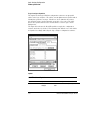
The figure below shows the Int ACK symbols set up by the configuration
software under the Cycle label. The following table lists the rest of the labels
and symbol encodings defined by the logic analyzer configuration software.
Symbols
80386EX Labels and Symbols
Label
CYCLE
3-8
Symbol
Int Ack
Halt/Spc
Status Encoding
000
001
Pod Location
P2[12..10]
E2454A 80386EX Analysis Probe
Logic Analyzer Configuration
Format specification
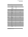
80386EX Labels and Symbols
Label
CYCLE (continued)
W/R#
D/C#
M/IO#
BS8#
LOCK#
HOLD
HLDA
ADS#
READY#
LBA#
RESET
UCS#
NMI#
NA#
RD#
WR#
BUSY#
ERROR#
Symbol
I/O Read
I/O Write
Opc Fetch
Mem Read
Mem Write
WRITE
READ
DATA
CODE
MEM
IO
16 BIT
8 BIT
OFF
LOCK
HOLD
OFF
HLDA
OFF
OFF
ADS
OFF
READY
-LBA
RESET
OFF
-UCS
-NMI
-NA
-RD
-WR
-BUSY
-ERROR
E2454A 80386EX Analysis Probe
Status Encoding
010
011
100
101
110
111
1
0
1
0
1
0
1
0
1
0
1
0
1
0
1
0
1
0
1
0
1
0
1
0
1
0
1
0
1
0
1
0
1
0
1
0
Pod Location
P2[10]
P2[11]
P2[12]
P2[13]
P4[5]
P4[6]
P4[7]
P4[8]
P4[9]
P4[10]
P4[11]
P4[13]
P4[14]
P4[15]
P5[8]
P5[9]
P6[12]
P6[14]
3-9
Logic Analyzer Configuration
To display the timing format specification
To display the timing format specification
The timing format specification is in the Format specification menu. Select
"Timing" from the State/Timing pop-up.
Chapter 4 of this guide contains a table that lists the signals for the Agilent
Technologies E2454A processor and on which analysis probe pod and probe
line the signal comes to the logic analyzer. Refer to this table and to the logic
analyzer connection information for your analyzer in chapter 2 to determine
where the processor signals should be on the timing format specification
screen.
The following figure shows the Timing format specification.
Timing Format Specification
3-10
E2454A 80386EX Analysis Probe
Logic Analyzer Configuration
To display captured timing data
To display captured timing data
To display captured timing data, select the Waveform menu for your logic
analyzer. The following figure shows the Waveform menu display:
Waveform Menu
E2454A 80386EX Analysis Probe
3-11
Using the Inverse Assemblers
The 80386 analysis probe contains two inverse assemblers, I386EX
and I386EXE. I386EXE contains all the functions of the I386EX
inverse assembler, plus additional features. For information on the
I386EXE features, see "The I386EXE inverse assembler" on page
3-21.
The configuration software checks the logic analyzer during the load
process. If the logic analyzer has the appropriate software version,
the configuration file loads the enhanced inverse assembler. For
information on the logic analyzer operating system version
requirements, refer to "Logic analyzer software version requirements"
on page 1-5.
The following sections describe the features common to both inverse
assemblers.
3-12
E2454A 80386EX Analysis Probe
Using the Inverse Assemblers
Listing menu
Listing menu
Captured data is displayed as shown below and on the next page. The
second listing has unexecuted prefetches suppressed. These figures display
the state listing after disassembly. The inverse assembler is constructed so
the mnemonic output closely resembles the actual assembly language source
code.
If your trace listing doesn’t otherwise appear to be correct (capturing the
same RAM address twice, for example), make sure the analysis probe
hardware is configured for state analysis. The "Invasm" field will appear at the
top of the Listing menu screen when the logic analyzer is configured for state
analysis. See Chapter 2 to review the hardware configuration, correct it if
needed, and then run the trace again.
State Listing
E2454A 80386EX Analysis Probe
3-13
Using the Inverse Assemblers
Listing menu
The figure below shows the listing display with the unexecuted prefetches
suppressed. A comparison of this figure and the one on the previous page
shows the display filtering.
State Listing with Unexecuted Prefetches Suppressed
3-14
E2454A 80386EX Analysis Probe
Using the Inverse Assemblers
To align the inverse assemblers
To align the inverse assemblers
The 80386 microprocessor fetches instructions 4-bytes (32-bits) wide at a
time in a single bus cycle. However, the microprocessor does not indicate
externally which of the bytes fetched is the first byte of an opcode fetch. You
must "point" to the first byte of an opcode fetch. Once aligned, the inverse
assembler disassembles from this state through the end of the display.
The 80386 microprocessor can execute the 80386 and 80386 instruction set
(32-bit) or the object code from Intel’s 16-bit microprocessor family,
including software designed for Intel’s 8086 and 80286. You must specify
whether the code being executed was originally designed to run on Intel’s 16
or 32-bit microprocessors when aligning the inverse assembler.
Use the following procedure to align the inverse assembler:
1 Select a line on the display that you know contains the first byte of an
instruction fetch.
2 Roll this line to the top of the display.
Do not roll the instruction to the line number field at the left center screen. In
the State Listing with Unexecuted Prefetches Suppressed, line 373 is the top of
the display.
E2454A 80386EX Analysis Probe
3-15
Using the Inverse Assemblers
To align the inverse assemblers
3 Select the appropriate field for your analyzer or inverse assembler.
a For the Agilent Technologies 16600/700 series analyzers, select
"Invasm," then select "Align." A pop-up menu appears with the
following choices:
0 4 8 C
SIZE 16
1 5 9 D
SIZE 32
2 6 A E
3 7 B F
Size, as used here, refers to the default operand size for this code.
This field toggles between 16 and 32.
b For the I386EXE inverse assembler in other logic analyzers, select
"Invasm Options" and use the "Code Synchronization" submenu. The
same choices as above are available.
c For the I386EX inverse assembler, select the "Invasm" field at the top
of the display. The following choices are available.
Size 16 Byte 0
Size 16 Byte 1
Size 16 Byte 2
Size 16 Byte 3
Size 32 Byte 0
Size 32 Byte 1
Size 32 Byte 2
Size 32 Byte 3
4 Select the choice that identifies which byte of the captured state
contains the first byte of the code fetch and what the default operand
size is for this code (16 or 32 bits).
5 Select "Align" to align the code.
The listing inverse assembles from the top line down. Any data before the
top of the display is left unchanged.
Rolling the display up inverse assembles the lines as they appear on the
bottom of the display. If you jump to another area of the display by entering
a new line number, you may need to re-align the inverse assembler by
repeating steps 1 through 5.
3-16
E2454A 80386EX Analysis Probe
Using the Inverse Assemblers
Inverse assembler output format
Inverse assembler output format
The following paragraphs explain the operation of the inverse assemblers and
the results you can expect in certain conditions.
Default Size (Code)
The 80386EX microprocessor can execute 32-bit object code from 80386
chips and 16-bit object code from 80286 and earlier chips. During execution,
loading a code segment descriptor determines the code size being executed.
This information cannot be detected by the inverse assembler. It must be
declared manually by selecting the correct field under the "Invasm" pop-up.
In the "Code Synchronization" group box, set "Default Size" to "Size 16" to
specify 16-bit operands and addresses; set "Default Size" to "Size 32" to
specify 32-bit operands and addresses.
"Size", as used here, has no relationship to the physical size of the
microprocessor’s data bus. Size indicates whether the code being executed
was originally designed to run on Intel’s 16-bit or 32-bit microprocessors.
If the inverse assembler seems to be disassembling incorrectly, and the
problem is neither prefetch activity nor storage qualification, it is likely that
the size attribute is set incorrectly.
Any instruction with an operand size of 32 bits (either by default, or by using
the operand override prefix) will be marked with an "=" symbol in the last
column of the mnemonic field of the listing display to help you distinguish
32-bit operands from 16-bit operands.
Logical Address Display
Physical, rather than logical addresses, are used to perform symbolic address
mapping. Most instructions, however, specify a 16-bit intrasegment offset
and may indicate a segment different from the default segment for that
particular instruction. Because the physical address cannot be determined
from this information alone, the inverse assembler must attempt to locate the
resulting bus cycle so that the physical address may be obtained. If a bus
cycle of the type indicated by the initiating instruction is not found, the
physical address cannot be determined and an unmapped logical address
(segment override, if any, and the 32-bit intrasegment offset) is displayed
instead of a mapped physical address.
E2454A 80386EX Analysis Probe
3-17
Using the Inverse Assemblers
Inverse assembler output format
Numeric Format
Hexadecimal output is followed by an "H". A "#" sign preceding a value
indicates an immediate value.
Multiple Instructions In a Single Fetch
Up to two instructions may be displayed for a single analyzer state, because
the 80386EX can fetch a word with two instruction bytes from program
memory. When a single state contains more than one instruction, each
instruction will be displayed on a separate line.
Multiple-Byte Instructions
Because an instruction may begin in any byte position, the last byte(s) of a
multiple-byte instruction may extend into the lower byte(s) of the next word
fetched. When interpreting a given state, the inverse assembler will ignore
the byte(s) used by a previous instruction and will only display instructions
that begin in that state.
Missing Opcodes
Asterisks (*) in the inverse assembler output indicate that a portion (or
portions) of an instruction was not captured by the analyzer. Missing
opcodes occur frequently and are primarily due to microprocessor prefetch
activity. Storage qualification, or the use of storage windows, can also lead to
such occurrences.
Don’t Care Bytes
The 80386EX microprocessor can perform byte, word, three-byte, and
double-word transfers between microprocessor registers and memory. Byte
transfers can occur in any byte on the 16-bit data bus. Word and three-byte
transfers can occur across any contiguous set of bytes that will hold the
transfer. The bytes that are valid in a transfer are indicated by the
microprocessor BLE# and BHE# lines. The inverse assembler displays "xx"
for any bytes in a transfer that are ignored by the microprocessor. You can
determine exactly which byte or bytes of data were used as an operand.
3-18
E2454A 80386EX Analysis Probe
Using the Inverse Assemblers
Inverse assembler output format
Unexecuted Prefetched Instructions
The analysis probe sends all of the bus transactions by the microprocessor to
the logic analyzer. Prefetched instructions which are not executed by the
microprocessor are marked by a hyphen "-".
In some cases, it is impossible to determine from bus activity whether a
branch is taken or a prefetch is executed. In these cases, the inverse
assembler marks the disassembled line with the prefix "?".
Prefetch Triggering
The logic analyzer captures prefetches, even if they are not executed. Care
must be taken when you are specifying a trigger condition or a storage
qualification that follows an instruction that may cause branching. An
unused prefetch may generate an unwanted trigger.
Since the microprocessor only prefetches at most four words, one technique
to avoid unwanted triggering from unused prefetches is to add "10 hex" to the
trigger address. This trigger condition will only be satisfied if the branch is
not taken.
E2454A 80386EX Analysis Probe
3-19
Using the Inverse Assemblers
Inverse assembler error messages
Inverse assembler error messages
Any of the following list of error messages may appear during analysis of your
target software. Included with each message is a brief explanation.
Illegal Task Request
Displayed if the microprocessor is used with an instrument other than a
supported logic analyzer.
Fatal Data Error
Displayed if the trace memory could not be read properly on entry into
the inverse assembler.
Invalid Status
Displayed if the status field for the current state is not valid.
Illegal Opcode
Displayed if the inverse assembler encounters an illegal instruction.
Reserved Opcode
Displayed if the inverse assembler encounters a reserved instruction.
No Operand
Displayed if the inverse assembler cannot find a complete operand field
for an instruction. Prefetch activity or storage qualification is often the
cause.
3-20
E2454A 80386EX Analysis Probe
Using the Inverse Assemblers
The I386EXE inverse assembler
The I386EXE inverse assembler
The enhanced inverse assembler contains all the functions of the other
inverse assembler (see previous sections), plus additional features.
The configuration software checks the logic analyzer during the load process.
If the logic analyzer has the appropriate software version, the configuration
file loads the enhanced inverse assembler. For information on the logic
analyzer operating system version requirements, refer to "Logic analyzer
software version requirements" on page 1-5.
The Invasm menu contains four functions: Load (Agilent Technologies
16600/700 only), Filtering with Show/Suppress selections, Align, and Options.
The following sections describe these functions.
Load
The Load function lets you load a different inverse assembler and apply it to
the data in the Listing menu. In some cases you may have acquired raw data,
in which case the Load function lets you apply an inverse assembler to that
data.
Filter
The Filter function brings up a Show/Suppress menu, Mode, and IDT
description entry. You can change the Show/Suppress settings to specify
whether the various microprocessor operations are shown or suppressed on
the logic analyzer display. The previous figure shows the microprocessor
operations which have this option. The settings for the various operations do
not affect the data which is stored by the logic analyzer, they only affect
whether that data is displayed or not. The same data can be examined with
different settings, for different analysis requirements.
This function allows faster analysis in two ways. First, unneeded information
can be filtered out of the display. Second, particular operations can be
isolated by suppressing all other operations. For example, I/O operations can
be shown, with all other operations suppressed, allowing quick analysis of I/O
operations.
The following figure shows the Filter menu.
E2454A 80386EX Analysis Probe
3-21
Using the Inverse Assemblers
The I386EXE inverse assembler
Filter Menu
If the X or O pattern markers are turned on, and the designated pattern is found
in a state that has been Suppressed with display filtering, the following
message will appear on the logic analyzer display: "X (or O) pattern found, but
state is suppressed."
3-22
E2454A 80386EX Analysis Probe
Using the Inverse Assemblers
The I386EXE inverse assembler
IDT Description
The IDT Description settings include Mode, IDT Start, and IDT Size. Mode
can be Protected, Real, or Virtual. IDT Start refers to the starting address of
the Interrupt Descriptor Table, and IDT Size refers to the size of the table.
Set these functions to match the target system settings.
In most cases, the inverse assembler can automatically determine the target
system settings, and will operate properly regardless of the settings entered.
The inverse assembler uses the information from these settings only in cases
of uncertainty. If you suspect that the inverse assembler is disassembling
improperly, check that these settings match your target system.
Align
Align enables the inverse assembler to re-align with the microprocessor code.
In some cases the prefetch marking algorithm in the inverse assembler may
lose synchronization, and unused prefetches or executed instructions may be
incorrectly marked. If any of the Code Reads are suppressed, this could
cause some executed instructions to be missing from the display.
To align the inverse assembler, use the procedure described earlier.
Options
The Options menu lets you change the width of the display.
E2454A 80386EX Analysis Probe
3-23
3-24
E2454A 80386EX Analysis Probe
4
Reference
Reference
This chapter contains additional reference information including the
signal mapping for the Agilent Technologies E2454A Analysis Probe.
The information in this chapter is presented in the following sections:
Overview
Chapter 1
Connecting &
Configuring
Your System
Chapter 2
•
•
•
•
•
Operating characteristics of the analysis probe
Theory of operation and clocking
Signal-to-connector mapping
Circuit board dimensions
Replaceable parts
Connecting
the Analysis
Probe to the
Target System
Connecting
the Analysis
Probe to the
Logic Analyzer
Configuring
Connecting
Optional
Equipment
Analyzing the
Target System
Chapter 3
Reference
Chapter 4
If You Have
a Problem
Chapter 5
4-2
E2454A 80386EX Analysis Probe
Reference
Operating characteristics
Operating characteristics
The following operating characteristics are not specifications, but are typical
operating characteristics for the analysis probe.
Operating Characteristics of the Analysis Probe
Microprocessor
Compatibility
Intel 80386EX microprocessor , and all microprocessors made by
other manufacturers that comply with Intel 80386EX specifications.
Microprocessor
Package
132-pin QF
144-pin TQFP (with E5336A Elastomeric Probing System)
Accessories
Required
132-pin QFP E3417A Probe Adapter (included)
144-pin TQFP E5336A Elastomeric Probing System (not included)
Power Requirements
1.0 mA at +5 Vdc maximum, supplied by the logic analyzer.
CAT I, Pollution degree 2.
Logic Analyzer
Required
Agilent Technologies 1660A/AS/C/CS/CP/E/ES/EP,
1661A/AS/C/CS/CP/E/ES/EP, 1662A/AS/C/CS/CP/E/ES/EP, 1670A/D/E,
1671A/D/E, 1672A/D/E, 16550A (one card), 16554A/55A/56A (one or two
cards), 16555D/56D/57D (one or two cards), 16600A, 16601A, 16602A,
16603A, 16710A (one card), 16711A (one card), 16712A (one card)
Logic Analyzer
Software Version
See chapter 1
Probes Required
Three high density 34-channel probes are available. Two are required
for inverse assembly.
Signal Line Loading
Approximately 15 pF on ADS#, READY#, HLDA, BHE#, BLE#, and NA#.
Approximately 8 pF on all other signals.
Timing Analysis
Approximately half of the signals are buffered by a 74FCT646ATQ gate,
with a 1 ns channel-to-channel skew. The remaining signals are
straight through with no buffering. Refer to the signal list later in this
chapter for exact information.
Environmental
Temperature
Operating
Nonoperating
0 to 55 degrees C (+32 to +131 degrees F)
-40 to +75 degrees C (-40 to +167 degrees F)
Altitude
Operating
Nonoperating
4,600 m (15,000 ft)
15,300 m (50,000 ft)
E2454A 80386EX Analysis Probe
4-3
Reference
Theory of operation and clocking
Operating Characteristics of the Analysis Probe
Humidity
Up to 90% noncondensing. Avoid sudden, extreme temperature
changes which could cause condensation within the instrument.
Theory of operation and clocking
The primary function of the Agilent Technologies E2454A Analysis Probe is
to connect the target microprocessor to the logic analyzer, and to perform
the interface logic required to identify address pipelining and 16-bit or 32-bit
cycles. The Agilent Technologies E2454A Analysis Probe performs this
primary function by:
• Latching and buffering the address, status, and data bus of the 80386EX
microprocessor so that address, status, and data can be sent to the logic
analyzer at the same time.
• Generating the logic analyzer clock from the appropriate 80386EX
microprocessor signals and bus conditions.
• Synthesizing address line A0 from the BHE# and BLE# lines so that the
inverse assembler can identify the address for A0.
The analysis probe duplicates the internal CLK signal of the 80386EX by
dividing the CLK2 signal by 2 and selecting the correct phase of the resulting
signal. This signal is called CLK and is used to identify 80386EX activities
inside the Agilent Technologies E2454A PAL.
The analysis probe detects the start of an 80386EX bus cycle when ADS#
goes true. If the 80386EX is in a non-pipelined cycle, address and status are
latched on the following rising edge of CLK2 after ADS# is asserted low.
Data is latched at the end of the 80386EX cycle. The end of the bus cycle is
defined as the rising edge of CLK2 when CLK is high and READY# is low
after ADS# has been asserted. The clock for the logic analyzer is generated
approximately 8 ns after the end of the cycle. The J clock for latching
information into the logic analyzer is generated by the PAL on the Agilent
Technologies E2454A each time the READY# signal goes low.
The K clock is for State-Per-Clock mode. It is one half the frequency of the
80386 CLK2. When using the analysis probe in the state per clock mode, set
K clk in the "Format" menu to trigger on the rising edge and falling edge of K
clk (make sure to also place the jumper on the J2 connector). Triggering on
4-4
E2454A 80386EX Analysis Probe
Reference
Theory of operation and clocking
every rising and falling edge of K clk is equivalent to triggering on every rising
edge of the microprocessor CLK2 signal.
The following figure shows a block diagram of the Agilent Technologies
E2454A Analysis Probe. A timing diagram for timing mode is shown on the
page after the block diagram.
Block Diagram
E2454A 80386EX Analysis Probe
4-5
Reference
Signal-to-connector mapping
Timing Mode
In timing mode, the J2 jumper is also required so that the latches on the
analysis probe act like flow-through buffers. The signals from the
microprocessor go directly from the target system to the logic analyzer, with
a one ns channel-to-channel skew. The skew for these signals relative to
unbuffered signals is typically five ns.
Timing Diagram
Signal-to-connector mapping
The following figures show the pin mapping for the microprocessors,
transition board, and analysis probe. The table after the diagram lists the
electrical interconnections implemented with the analysis probe. Refer to the
documentation that came with your flexible adapter for its pin mapping.
4-6
E2454A 80386EX Analysis Probe
Reference
Signal-to-connector mapping
132-pin QFP Target Pin Mapping
E2454A 80386EX Analysis Probe
4-7
Reference
Signal-to-connector mapping
144-pin TQFP Target Pin Mapping
4-8
E2454A 80386EX Analysis Probe
Reference
Signal-to-connector mapping
144-pin TQFP Target Pin Mapping (continued)
This diagram shows the female connectors on the
Agilent Technologies E3442A transition board. It shows
the relationship of connections from the 144-pin
microprocessor to the 132-pin analysis probe. Since the
transition board stays fixed with the analysis probe, the
pinouts are the same for all orientations of the 144-pin
flexible adapter.
E2454A 80386EX Analysis Probe
4-9
Reference
Signal-to-connector mapping
The signal list table column descriptions are as follows:
POD
LA PROBE
PIN NAME
PQFP PIN
TQFP PIN
LABEL
ALT LABEL
BUFFRD?
The analysis probe pod the signal that carries the signal.
The probe within the pod that carries the signal.
The processor mnemonic for the pin.
The PQFP processor pin number for the signal.
The TQFP processor pin number for the signal.
The analyzer label assigned to the signal.
An additional label also assigned to the signal (if any).
Whether the processor signal is buffered. All signals not marked yes are
straight through.
80386EX Signal List
POD
P1
P1
P1
P1
LA
PROBE
0
1
2
3
PIN
NAME
A0
A1
A2
A3
PQFP
PIN
*
42
43
44
TQFP
PIN
*
44
46
48
LABEL
ADDR
ADDR
ADDR
ADDR
ALT
LABEL
P1
P1
P1
P1
4
5
6
7
A4
A5
A6
A7
45
48
49
50
49
52
53
54
ADDR
ADDR
ADDR
ADDR
Yes
Yes
Yes
Yes
P1
P1
P1
P1
8
9
10
11
A8
A9
A10
A11
51
52
53
54
55
56
57
58
ADDR
ADDR
ADDR
ADDR
Yes
Yes
Yes
Yes
P1
P1
P1
P1
12
13
14
15
A12
A13
A14
A15
55
56
57
58
60
62
63
64
ADDR
ADDR
ADDR
ADDR
Yes
Yes
Yes
Yes
P1
CLK
*
*
JCLK
Yes
BUFFRD?
Yes
Yes
Yes
Yes
* This signal is generated by the analysis probe.
4-10
E2454A 80386EX Analysis Probe
Reference
Signal-to-connector mapping
80386EX Signal List (continued)
POD
P2
P2
P2
P2
LA
PROBE
0
1
2
3
PIN
NAME
A16
A17
A18
A19
PQFP
PIN
59
61
62
63
TQFP
PIN
65
66
67
68
LABEL
ADDR
ADDR
ADDR
ADDR
ALT
LABEL
P2
P2
P2
P2
4
5
6
7
A20
A21
A22
A23
65
66
67
68
70
71
73
74
ADDR
ADDR
ADDR
ADDR
Yes
Yes
Yes
Yes
P2
P2
P2
P2
8
9
10
11
A24
A25
W/R#
D/C#
70
72
30
29
76
77
32
31
ADDR
ADDR
STAT
STAT
Yes
Yes
Yes
Yes
P2
P2
P2
P2
12
13
14
15
M/IO#
BS8#
BLE#
BHE#
27
33
37
39
30
35
40
41
STAT
STAT
STAT
STAT
Yes
Yes
Yes
Yes
P2
CLK
*
*
KCLK
Yes
BUFFRD?
Yes
Yes
Yes
Yes
* This signal is generated by the analysis probe.
E2454A 80386EX Analysis Probe
4-11
Reference
Signal-to-connector mapping
80386EX Signal List (continued)
POD
P3
P3
P3
P3
LA
PROBE
0
1
2
3
PIN
NAME
D0
D1
D2
D3
PQFP
PIN
5
6
7
8
TQFP
PIN
5
6
7
8
LABEL
DATA
DATA
DATA
DATA
P3
P3
P3
P3
4
5
6
7
D4
D5
D6
D7
10
11
12
13
10
12
13
14
DATA
DATA
DATA
DATA
Yes
Yes
Yes
Yes
P3
P3
P3
P3
8
9
10
11
D8
D9
D10
D11
14
16
18
19
15
17
19
20
DATA
DATA
DATA
DATA
Yes
Yes
Yes
Yes
P3
P3
P3
P3
12
13
14
15
D12
D13
D14
D15
20
21
22
23
21
22
24
26
DATA
DATA
DATA
DATA
Yes
Yes
Yes
Yes
P3
CLK
P1.5/LOCK#
106
116
LOCK#
Yes
4-12
ALT
LABEL
BUFFRD?
Yes
Yes
Yes
Yes
E2454A 80386EX Analysis Probe
Reference
Signal-to-connector mapping
80386EX Signal List (continued)
POD
P4
P4
P4
P4
LA
PROBE
0
1
2
3
PIN
NAME
P1.0/DCD0#
P1.1/RTS0#
P1.2/DTR0#
P1.3/DSR0#
PQFP
PIN
101
102
104
105
TQFP
PIN
110
111
113
114
LABEL
PORT1
PORT1
PORT1
PORT1
ALT
LABEL
DC0#
RTS0#
DTR0#
DSR0#
P4
P4
P4
P4
4
5
6
7
P1.4/RIO#
P1.5/LOCK#
P1.6/HOLD
P1.7/HLDA
106
107
108
111
115
116
117
121
PORT1
PORT1
PORT1
PORT1
RIO#
LOCK#
HOLD
HLDA
P4
P4
P4
P4
8
9
10
11
ADS#
READY#
LBA#
RESET
40
32
4
110
42
34
4
119
ADS#
READY#
LBA#
RESET
P4
P4
P4
P4
12
13
14
15
DRQ0/DCD1#
UCS#
NMI
NA#
117
1
90
41
128
1
98
43
DRQ0
UCS#
NMI
NA#
DCD1#
P4
CLK
RI1#/SSIORX
78
85
RI1#
SSIORX
E2454A 80386EX Analysis Probe
BUFFRD?
Yes
Yes
Yes
Yes
Yes
4-13
Reference
Signal-to-connector mapping
80386EX Signal List (continued)
POD
P5
P5
P5
P5
LA
PROBE
0
1
2
3
PIN
NAME
P2.0/CS0#
P2.1/CS1#
P2.2/CS2#
P2.3/CS3#
PQFP
PIN
122
123
124
125
TQFP
PIN
134
135
136
137
LABEL
PORT2
PORT2
PORT2
PORT2
ALT
LABEL
GCS
GCS
GCS
GCS
P5
P5
P5
P5
4
5
6
7
P2.4/CS4#
P2.5/RXD0
P2.6/TXD0
P2.7/CTS0#
126
129
131
132
138
140
142
143
PORT2
PORT2
PORT2
PORT2
GCS
RXD0
TXD0#
CTS0#
P5
P5
P5
P5
8
9
10
11
RD#
WR#
DACK0/GCS5#
DACK1/TXD1
34
35
128
112
37
38
139
122
RD#
WR#
DACK
DACK
P5
P5
P5
P5
12
13
14
15
EOP#/CTS1#
REFRESH#
SMI#
SMI_ACT#
113
2
73
120
123
2
78
131
EOP#
REFRESH#
SMI#
SMI_ACT#
P5
CLK
FLT#
99
107
FLT#
4-14
BUFFRD?
Yes
Yes
GCS
TXD1
CTS1#
E2454A 80386EX Analysis Probe
Reference
Signal-to-connector mapping
80386EX Signal List (continued)
POD
LA
PROBE
PIN
NAME
PQFP
PIN
TQFP
PIN
LABEL
ALT
LABEL
P6
P6
P6
P6
0
1
2
3
P3.0/TMROUT0
P3.1/TMROUT1
P3.2/INT0
P3.3/INT1
74
75
80
82
79
80
87
89
PORT3
PORT3
PORT3
PORT3
TMROUT
TMROUT
INT
INT
P6
P6
P6
P6
4
5
6
7
P3.4/INT2
P3.5/INT3
P3.6/PWRDOWN
P3.7/COMCLK
84
85
86
87
91
92
93
94
PORT3
PORT3
PORT3
PORT3
INT
INT
PWRDOW
COMCLK
P6
P6
P6
P6
8
9
10
11
INT4/TMRCLK0
INT5/TMRGAT0
INT6/TMRCLK1
INT7/TMRGAT1
93
94
95
96
101
102
103
104
TMRCLK
TGATE
TMRCLK
TGATE
INT
INT
INT
INT
P6
P6
P6
P6
12
13
14
15
BUSY#/TMRG2
PEREQ/TMRC2
ERROR#/TMROU
RTS1#/SSIOTX
92
89
91
79
100
96
99
86
TGATE
TMRCLK
ERROR#
RTS1#
BUSY#
PEREQ
TMROUT
SSIOTX
P6
CLK
WDTOUT
114
124
WDTOUT
E2454A 80386EX Analysis Probe
BUFFRD?
4-15
Circuit board dimensions
The following figure gives the dimensions for the analysis probe assembly.
The dimensions are listed in inches and millimeters.
Analysis Probe Dimensions
4-16
E2454A 80386EX Analysis Probe
Reference
Replaceable parts
Replaceable parts
The repair strategy for this analysis probe is board replacement. However,
the following table lists some mechanical parts that may be replaced if they
are damaged or lost. Contact your nearest Agilent Technologies Sales Office
for further information on servicing the board.
Exchange assemblies are available when a repairable assembly is returned to
Agilent Technologies. These assemblies have been set up on the "Exchange
Assembly" program. This allows you to exchange a faulty assembly with one
that has been repaired, calibrated, and performance verified by the factory.
The cost is significantly less than that of a new assembly.
Replaceable Parts
Agilent Part Number
Description
E2454A Analysis Probe
E2454-69501
Circuit board assembly
E2454-68701
Inverse assembler disk pouch
E3417A
Generic PGA to 132-pin QFP probe adapter
1200-1712
PGA pin protector socket
E5336A Elastomeric Probing System
E5336A
Elastomeric probe adapter for 144-pin TQFP
E5338A
General-purpose flexible adapter
E3442A
Transition socket
E2454A 80386EX Analysis Probe
4-17
4-18
E2454A 80386EX Analysis Probe
5
If You Have a Problem
If You Have a Problem
Overview
Chapter 1
Connecting &
Configuring
Your System
Chapter 2
Connecting
the Analysis
Probe to the
Target System
Connecting
the Analysis
Probe to the
Logic Analyzer
Configuring
Connecting
Optional
Equipment
Analyzing the
Target System
Chapter 3
Occasionally, a measurement may not give the expected results. If
you encounter difficulties while making measurements, use this
chapter to guide you through some possible solutions. Each heading
lists a problem you may encounter, along with some possible
solutions.
The information in this chapter is presented in the following sections:
•
•
•
•
•
•
Logic analyzer problems
Analysis probe problems
Inverse assembler problems
Intermodule measurement problems
Messages
Cleaning the instrument
If you still have difficulty after trying the suggestions in this chapter,
contact your local Agilent Technologies Service Center.
Reference
Chapter 4
If You Have
a Problem
Chapter 5
CAUTION
When you are working with the analyzer, be sure to power down both the
analyzer and the target system before disconnecting or connecting cables,
probes, and analysis probes. Otherwise, you may damage circuitry in the
analyzer, analysis probe, or target system.
5–2
E2454A 80386EX Analysis Probe
Analyzer Problems
This section lists general problems that you might encounter while
using the analyzer.
Intermittent data errors
This problem is usually caused by poor connections, incorrect signal levels, or
marginal timing.
Remove and reseat all cables and probes, ensuring that there are no bent
pins on the analysis probe or poor probe connections.
Adjust the threshold level of the data pod to match the logic levels in the
system under test.
Use an oscilloscope to check the signal integrity of the data lines.
Clock signals for the state analyzer must meet particular pulse shape and
timing requirements. Data inputs for the analyzer must meet pulse shape and
setup and hold time requirements.
See Also
See “Capacitive loading” in this chapter for information on other sources of
intermittent data errors.
Unwanted triggers
Unwanted triggers can be caused by instructions that were fetched but not
executed.
Add the prefetch queue or pipeline depth to the trigger address to avoid
this problem.
The logic analyzer captures prefetches, even if they are not executed. When
you are specifying a trigger condition or a storage qualification that follows an
instruction that may cause branching, an unused prefetch may generate an
unwanted trigger.
E2454A 80386EX Analysis Probe
5–3
Analyzer Problems
No activity on activity indicators
No activity on activity indicators
Check for loose cables, board connections, and analysis probe
connections.
Check for bent or damaged pins on the analysis probe.
No trace list display
If there is no trace list display, it may be that your trigger specification is not
correct for the data you want to capture, or that the trace memory is only
partially filled.
Check your trigger sequencer specification to ensure that it will capture
the events of interest.
Try stopping the analyzer; if the trace list is partially filled, this should
display the contents of trace memory.
Analyzer won’t power up
If the logic analyzer power is powered down when it is connected to a
powered-up target system, the logic analyzer may not be able to power up.
Some logic analyzers are inhibited from powering up when they are
connected to a target system that is already powered up.
Disconnect all logic analyzer cabling from the analysis probe. This will
allow the logic analyzer to power up. Reconnect logic analyzer cabling
after power up.
5–4
E2454A 80386EX Analysis Probe
Analysis Probe Problems
This section lists problems that you might encounter when using an
analysis probe. If the solutions suggested here do not correct the
problem, you may have a damaged analysis probe. Contact your local
Agilent Technologies Sales Office if you need further assistance.
Target system will not boot up
If the target system will not boot up after connecting the analysis probe, the
microprocessor (if socketed) or the analysis probe may not be installed
properly, or they may not be making electrical contact.
Ensure that you are following the correct power-on sequence for the
analysis probe and target system.
1 Power up the analyzer and analysis probe.
2 Power up the target system.
If you power up the target system before you power up the analysis probe,
interface circuitry in the analysis probe may latch up and prevent proper
target system operation.
Verify that the microprocessor and the analysis probe are properly
rotated and aligned so that the index pin on the microprocessor (pin 1 or
pin A1) matches the index pin on the analysis probe.
Verify that the microprocessor and the analysis probe are securely
inserted into their respective sockets.
Verify that the logic analyzer cables are in the proper sockets of the
analysis probe and are firmly inserted.
E2454A 80386EX Analysis Probe
5–5
Analysis Probe Problems
Erratic trace measurements
Erratic trace measurements
There are several general problems that can cause erratic variations in trace
lists and inverse assembly failures.
Do a full reset of the target system before beginning the measurement.
Some analysis probe designs require a full reset to ensure correct
configuration.
Ensure that your target system meets the timing requirements of the
processor with the analysis probe installed.
See “Capacitive Loading” in this chapter. While analysis probe loading is
slight, pin protectors, extenders, and adapters may increase it to
unacceptable levels. If the target system design has close timing margins,
such loading may cause incorrect processor functioning and give erratic trace
results.
Ensure that you have sufficient cooling for the microprocessor.
Some microprocessors generate substantial heat. This is exacerbated by the
active circuitry on the analysis probe board. You should ensure that you have
ambient temperature conditions and airflow that meet or exceed the
requirements of the microprocessor manufacturer.
Capacitive loading
Excessive capacitive loading can degrade signals, resulting in incorrect
capture by the analysis probe, or system lockup in the microprocessor. All
analysis probes add additional capacitive loading, as can custom probe
fixtures you design for your application.
Careful layout of your target system can minimize loading problems and
result in better margins for your design. This is especially important for
systems that are running at frequencies greater than 50 MHz.
Remove as many pin protectors, extenders, and adapters as possible.
If multiple analysis probe solutions are available, use one with lower
capacitive loading.
5–6
E2454A 80386EX Analysis Probe
Inverse Assembler Problems
This section lists problems that you might encounter while using the
inverse assembler.
When you obtain incorrect inverse assembly results, it may be unclear
whether the problem is in the analysis probe or in your target system.
If you follow the suggestions in this section to ensure that you are
using the analysis probe and inverse assembler correctly, you can
proceed with confidence in debugging your target system.
No inverse assembly or incorrect inverse assembly
This problem may be due to incorrect alignment, modified configuration files,
incorrect connections, or a hardware problem in the target system. A locked
status line can cause incorrect or incomplete inverse assembly.
Ensure that each logic analyzer pod is connected to the correct analysis
probe connector.
There is not always a one-to-one correspondence between analyzer pod
numbers and analysis probe cable numbers. Microprocessor interfaces must
supply address (ADDR), data (DATA), and status (STAT) information to the
analyzer in a predefined order. The cable connections for each analysis
probe are often altered to support that need. Thus, one analysis probe might
require that you connect cable 2 to analyzer pod 2, while another will require
you to connect cable 5 to analyzer pod 2. See Chapter 2 for connection
information.
Check the activity indicators for status lines locked in a high or low
state.
Verify that the STAT, DATA, and ADDR format labels have not been
modified from their default values.
These labels must remain as they are configured by the configuration file. Do
not change the names of these labels or the bit assignments within the labels.
Some analysis probes also require other data labels. See Chapter 3 for more
information.
E2454A 80386EX Analysis Probe
5–7
Inverse Assembler Problems
Inverse assembler will not load or run
Verify that all microprocessor caches and memory managers have been
disabled.
In most cases, if the microprocessor caches and memory managers remain
enabled you should still get inverse assembly. It may be incorrect because a
portion of the execution trace was not visible to the logic analyzer.
Verify that storage qualification has not excluded storage of all the
needed opcodes and operands.
Inverse assembler will not load or run
You need to ensure that you have the correct system software loaded on your
analyzer.
For the Agilent Technologies 16600/700 logic analysis systems, the
inverse assembler must be installed on the hard drive using the
procedures listed on the jacket for the CD ROM. Re-install the
Processor Support Package for this product, then try loading the
configuration file again.
For other logic analyzers, ensure that the inverse assembler is on the
same disk as the configuration files you are loading.
Configuration files for the state analyzer contain a pointer to the name of the
corresponding inverse assembler. If you delete the inverse assembler, rename
it, or use the File Manager Copy command to copy it to the Agilent
Technologies 16600/700 logic analysis systems, the configuration process will
fail to load the inverse assembler.
See Chapter 3 for details.
5–8
E2454A 80386EX Analysis Probe
Intermodule Measurement Problems
Some problems occur only when you are trying to make a
measurement involving multiple modules.
An event wasn’t captured by one of the modules
If you are trying to capture an event that occurs very shortly after the event
that arms one of the measurement modules, it may be missed due to internal
analyzer delays. For example, suppose you set the oscilloscope to trigger
upon receiving a trigger signal from the logic analyzer because you are trying
to capture a pulse that occurs right after the analyzer’s trigger state. If the
pulse occurs too soon after the analyzer’s trigger state, the oscilloscope will
miss the pulse.
Adjust the skew in the Intermodule menu.
You may be able to specify a skew value that enables the event to be
captured.
Change the trigger specification for modules upstream of the one with
the problem.
If you are using a logic analyzer to trigger the scope, try specifying a trigger
condition one state before the one you are using. This may be more difficult
than working with the skew because the prior state may occur more often
and may not always be related to the event you are trying to capture with the
oscilloscope.
E2454A 80386EX Analysis Probe
5–9
Analyzer Messages
This section lists some of the messages that the analyzer displays
when it encounters a problem.
“. . . Enhanced Inverse Assembler Not Found”
This error only occurs on the Agilent Technologies 16600/700 logic analysis
systems. This error occurs if you rename or delete the enhanced inverse
assembler file that is attached to the configuration file, or if you do not
properly install the inverse assembler file on the hard disk. Ensure that the
inverse assembler file is not renamed or deleted. If you use the File Manager
Copy command to copy an inverse assembler to the Agilent Technologies
16600/700 logic analysis systems, the enhanced inverse assembler will not
load. Use the Install procedures listed on the jacket of the CD ROM to install
the files for this product.
“. . . Inverse Assembler Not Found”
This error occurs if you rename or delete the inverse assembler file that is
attached to the configuration file. Ensure that the inverse assembler file is
not renamed or deleted.
For the Agilent Technologies 16600/700 logic analysis systems, the inverse
assembler must be installed on the hard drive using the procedures listed on
the jacket for the CD ROM.
For other logic analyzers, if you have copied the files to the logic analyzer
hard disk, ensure that the inverse assembler is located in the same directory
as the configuration file.
“. . . Does Not Appear to be an Inverse Assembler File”
This error occurs if the inverse assembler file requested by the configuration
file is not a valid inverse assembler. Use the Install procedures listed on the
jacket of the CD ROM to re-install the files for this product.
5–10
E2454A 80386EX Analysis Probe
Analyzer Messages
“Measurement Initialization Error”
“Measurement Initialization Error”
This error occurs when you have installed the cables incorrectly on logic
analysis cards. The following diagrams show the correct cable connections
for one-card and two-card Agilent Technologies 16550A installations. Ensure
that your cable connections match the silk screening on the card, and that
they are fully seated in the connectors. Then, repeat the measurement.
Cable Connections for One-Card Agilent Technologies 16550A Installations
Cable Connections for Two-Card Agilent Technologies 16550A Installations
See Also
The Agilent Technologies 16550A 100-MHz State/500-MHz Timing Logic
Analyzer Service Guide.
E2454A 80386EX Analysis Probe
5–11
Analyzer Messages
“Measurement Initialization Error”
The following diagrams show the correct cable connections for one-card,
two-card, and three-card installations on Agilent Technologies 16554A,
Agilent Technologies 16555A/D, and Agilent Technologies 16556A/D logic
analysis cards. Ensure that your cable connections match the silk screening
on the card, and that they are fully seated in the connectors. Then, repeat
the measurement.
Cable Connections for One-Card Agilent Technologies 16554/55/56 Installations
5–12
E2454A 80386EX Analysis Probe
Analyzer Messages
“Measurement Initialization Error”
Cable Connections for Two-Card Agilent Technologies 16554/55/56 Installations
Cable Connections for Three-Card Agilent Technologies 16554/55/56 Installations
See Also
The Agilent Technologies 16554A 70-MHz State/250-MHz Timing Logic
Analyzer Service Guide.
The Agilent Technologies 16555A 110-MHz State/250-MHz Timing Logic
Analyzer Service Guide.
The Agilent Technologies 16556A 100-MHz State/400-MHz Timing Logic
Analyzer Service Guide.
E2454A 80386EX Analysis Probe
5–13
Analyzer Messages
“No Configuration File Loaded”
“No Configuration File Loaded”
This is usually caused by trying to load a configuration file for one type of
module/system into a different type of module/system.
Verify that the appropriate module has been selected from the Load
{module} from File {filename} in the Agilent Technologies 16500A/B/C
disk operation menu. Selecting Load {All} will cause incorrect operation
when loading most analysis probe configuration files.
See Also
Chapter 2 describes how to load configuration files.
“Selected File is Incompatible”
This occurs when you try to load a configuration file for the wrong module.
Ensure that you are loading the appropriate configuration file for your logic
analyzer.
“Slow or Missing Clock”
This error message might occur if the logic analyzer cards are not firmly
seated in the logic analysis system mainframe. Ensure that the cards are
firmly seated.
This error might occur if the target system is not running properly.
Ensure that the target system is on and operating properly.
If the error message persists, check that the logic analyzer pods are
connected to the proper connectors on the analysis probe. See Chapter 2
to determine the proper connections.
5–14
E2454A 80386EX Analysis Probe
Analyzer Messages
“Time from Arm Greater Than 41.93 ms”
“Time from Arm Greater Than 41.93 ms”
The state/timing analyzers have a counter to keep track of the time from
when an analyzer is armed to when it triggers. The width and clock rate of
this counter allow it to count for up to 41.93 ms before it overflows. Once the
counter has overflowed, the system does not have the data it needs to
calculate the time between module triggers. The system must know this time
to be able to display data from multiple modules on a single screen.
“Waiting for Trigger”
If a trigger pattern is specified, this message indicates that the specified
trigger pattern has not occurred. Verify that the triggering pattern is
correctly set.
When analyzing microprocessors that fetch only from word-aligned
addresses, if the trigger condition is set to look for an opcode fetch at an
address not corresponding to a word boundary, the trigger will never be
found.
E2454A 80386EX Analysis Probe
5–15
Cleaning the Instrument
If this instrument requires cleaning, disconnect it from all power
sources and clean it with a mild detergent and water. Make sure the
instrument is completely dry before reconnecting it to a power source.
5–16
E2454A 80386EX Analysis Probe
Glossary
Analysis Probe A probe connected to the target microprocessor.
It provides an interface between the
signals of the target microprocessor
and the inputs of the logic analyzer.
Connector Board A board whose
only function is to provide connections from one location to another.
One or more connector boards might
be stacked to raise a probe above a
target micoprocessor to avoid mechanical contact with other
components installed close to the target microprocessor.
Elastomeric Probe Adapter A
connector that is fastened on top of
a target microprocessor using a retainer and knurled nut. The
conductive elastomer on the bottom
of the probe adapter makes contact
with pins of the target microprocessor and delivers their signals to
connection points on top of the
probe adapter.
Emulation Module An emulation
module is installed within the mainframe of a logic analyzer. It provides
run control within an emulation and
analysis test setup. See Emulation
Probe.
Emulation Probe An emulation
probe is a stand-alone instrument
connected to the mainframe of a
logic analyzer. It provides run control within an emulation and analysis
test setup. See Emulation Module.
Flexible Adapter Two connection devices coupled with a flexible
cable. Used for connecting probing
hardware on the target microprocessor to the analysis probe.
General-purpose Flexible Adapter
A cable assembly that connects the
signals from an elastomeric probe
adapter to an analysis probe. Normally, a male-to-male header or
transition board makes the connections from the general-purpose
flexible adapter to the analysis probe.
High-Density Adapter Cable A
cable assembly that delivers signals
from an analysis probe hardware interface to the logic analyzer pod
cables. A high-density adapter cable
has a single Mictor connector that is
installed into the analysis probe, and
two cables that are connected to corresponding odd and even logic
analyzer pod cables.
High Density Termination Adapter
Cable Same as a High Density
Adapter Cable, except it has a termination in the Mictor connector.
Glossary-1
Glossary
Jumper Moveable direct electrical
connection between two points.
Mainframe Logic Analyzer A
logic analyzer that resides on one or
more board assemblies installed in
an Agilent Technologies 16500B/C,
1660xA, or 16700A mainframe.
Male-to-male Header A board assembly that makes point-to-point
connections between the female pins
of a flexible adapter or transition
board and the female pins of an
analysis probe.
Preprocessor Interface See
Analysis Probe.
Preprocessor Probe See Analysis
Probe.
Probe adapter See Elastomeric
Probe Adapter.
Processor Probe See Emulation
Probe and Emulation Module.
Prototype Analyzer The Agilent
Technologies 16505A prototype analyzer acts as an analysis and display
processor for the Agilent Technologies 16500B/C logic analysis system.
It provides a windowed interface and
powerful analysis capabilities.
Glossary-2
Setup Assistant A software program that guides you through the
process of connecting and configuring an analysis probe and logic
analyzer to make measurements on a
specific microprocessor.
Shunt Connector. See Jumper.
Stand-alone Logic Analyzer A
stand-alone logic analyzer has a predefined set of hardware components
which provide a specific set of capabilities. It is designed to perform
logic analysis. A stand-alone logic
analyzer differs from a mainframe
logic analyzer in that it does not offer card slots for installation of
additional capabilities, and its specifications are not modified based upon
selection from a set of optional hardware boards that might be installed
within its frame.
Transition Board A board assembly that obtains signals connected to
one side and re-arranges them in a
different order for delivery at the
other side of the board.
1/4-Flexible Adapter An adapter
that obtains one-quarter of the signals from an elastomeric probe
adapter (one side of a target microprocessor) and makes them available
for probing.
Index
!
# (pound) symbol, 3–18
* (asterisk) symbol, 3–18
- (hyphen) symbol, 3–19
? (question mark) symbol, 3–19
A
accessories required, 1–9
adapter board
removal, 2–8
ADDR
modifying, 3–5, 5–7
address
physical, 3–17
Align field, 3–16
Align function, 3–23
aligning the inverse assembler, 3–15
analysis probe
accessories required, 1–9
capacitive loading, 5–6
cleaning, 5–16
configuration, 2–28
connection procedure, 2–5
equipment required, 1–9
equipment supplied, 1–7
equipment supplied illustration, 1–8
erratic trace measurements, 5–6
illustration, with logic analyzer, –iii
inverse assembly, 3–12
microprocessors supported, –ii
modes of operation, 2–28, 3–3
overview, –ii
pod locations, 2–13
pods required for inverse assembly, 2–12
power on/power off sequence, 2–4
target system will not boot up, 5–5
troubleshooting, 5–5
analyzer problems, 5–3
capacitive loading, 5–6
intermittent data errors, 5–3
unwanted triggers, 5–3
C
capacitive loading, 5–6
circuit board
dimensions, 4–16
part number, 4–17
Code Synchronization menu, 3–23
configuration
analysis probe, 2–28
logic analyzers, 2–29, 3–5
overview, 2–27
configuration files
loading, 2–29
table, 2–32
connection
analysis probe to target system, 2–5
QFP target systems, 2–6
sequence, 2–3
TQFP target systems, 2–9
connector mapping, 4–6
D
DATA
display, 3–13
errors, 5–3
modifying, 3–5, 5–7
dimensions
circuit board, 4–16
double-density cables, 2–13
IDT Description menu, 3–23
Illegal Opcode, 3–20
Illegal Task Request, 3–20
Intermodule Measurement problems, 5–9
an event wasn’t captured, 5–9
Interrupt Descriptor Table, 3–23
Invalid Status, 3–20
Invasm field, 3–16
Invasm menu, 3–16
Invasm Options field, 3–16
inverse assembler, 3–12 to 3–23
aligning, 3–15
enhanced version, 3–21
error messages, 3–20
I386EX, 3–12
I386EXE, 3–21
invalid inverse assembler file, 5–10
loading files, 2–30 to 2–31
output format, 3–17
requirements for enhanced, 1–6
synchronizing, 3–15
troubleshooting, 5–7
Inverse Assembler Not Found, 5–10
inverse assembler problems, 5–7
incorrect inverse assembly, 5–7
no inverse assembly, 5–7
will not load or run, 5–8
inverse assembly
logic analyzer pods required, 2–12
E
enhanced inverse assembler
features, 3–21 to 3–23
logic analyzer requirements, 1–6
Enhanced Inverse Assembler Not Found,
5–10
equipment
optional equipment supported, 1–9, 2–33
L
required, 1–9
Listing menu, 3–13
supplied, 1–7
Load menu, 3–21
supported, 1–9
logic analyzer
error messages, 3–20, 5–10
double-density cables, 2–13
extractor tool, 2–8
logic analyzers
Agilent Technologies 16550 connections,
F
2–18
Fatal Data Error, 3–20
Agilent Technologies 16554/55/56 series
Filter menu, 3–21 to 3–22
connections, 2–19 to 2–20
flexible adapter
Agilent Technologies 1660 series
connecting, TQFP target systems, 2–11
connection, 2–21
floppy disks
Agilent Technologies 16600 and 16700
duplicating, 2–31
series, 1–3
Format menu, 3–5
Agilent Technologies 16600 connections,
2–14
I
Agilent Technologies 16601 connections,
2–15
Agilent Technologies 16602 connections,
Index-1
Index
2–16
Agilent Technologies 16603 connections,
2–17
Agilent Technologies 1661 series
connections, 2–22
Agilent Technologies 1662 series
connections, 2–23
Agilent Technologies 1670 series
connections, 2–24
Agilent Technologies 1671 series
connections, 2–25
Agilent Technologies 1672 series
connections, 2–26
configuration overview, 3–5
configuring, 2–30 to 2–31
connection overview, 2–12
error messages, 5–10
loading configuration files, 2–29
software version requirements, 1–6
supported, 1–4
troubleshooting, 5–3
logical address, 3–17
unmapped, 3–17
physical address, 3–17
pin mapping
132-pin, 4–7
144-pin, 4–8 to 4–9
pin protector
part number, 4–17
pod locations, 2–13
power on/power off sequence, 2–4
power troubleshooting, 5–4
prefetches, 5–3
suppressed, 3–14 to 3–15
unexecuted, 3–19
Protected mode, 3–23
Q
QFP target systems, 2–6
R
Real mode, 3–23
Reserved Opcode, 3–20
O
online configuration help, 1–3
opcodes
missing, 3–18
operating characteristics, 4–3
operating modes for analysis probe, 3–4
Options menu, 3–23
S
Selected File is Incompatible, 5–14
Setup Assistant, 1–3
Show/Suppress menu, 3–21
size, 3–16
of microprocessor code, 3–17
Slow or Missing Clock, 5–14
software requirements, 1–6
STAT
encoding, 3–7
label, 3–7
modifying, 3–5, 5–7
State-per-clock
configuration, 2–28
mode of operation, 3–3
State-per-transfer
configuration, 2–28
mode of operation, 3–3
State/Timing jumper configuration, 2–28
status bits, 3–7
status encoding, 3–7
storage qualification, 3–18
symbols table, 3–8
P
T
M
Measurement Initialization Error, 5–11
measurements
equipment required, 1–9
microprocessors supported, –ii
missing opcodes, 3–18
modes of operation, 3–3
configuring, 2–28
N
No Configuration File Loaded, 5–14
numeric format, 3–18
Index-2
target system
power sequence, 2–4
TQFP connections, 2–9
will not boot, 5–5
Time from Arm Greater Than 41.93 ms,
5–15
Timing
configuration, 2–28
mode of operation, 3–4
Waveform menu, 3–11
TQFP target systems
connection, 2–9
rotation illustration, 2–10
Trace specification, 3–5, 5–4, 5–6
triggering, 3–19, 5–3
troubleshooting, 5–2
U
unexecuted prefetches, 5–3
suppressed, 3–14
User’s Guide overview, –iv
V
Virtual mode, 3–23
W
Waiting for Trigger, 5–15
Waveform menu, 3–11
X
X (or O) pattern found..., 3–22
xx symbol, 3–18
© Copyright Agilent
Technologies 1994-2000
All Rights Reserved.
Reproduction, adaptation, or
translation without prior
written permission is
prohibited, except as allowed
under the copyright laws.
Restricted Rights Legend
Use, duplication, or
disclosure by the U.S.
Government is subject to
restrictions set forth in
subparagraph (C) (1) (ii) of
the Rights in Technical Data
and Computer Software
Clause in DFARS
252.227-7013. Agilent
Technologies, 3000 Hanover
Street, Palo Alto, CA 94304
U.S.A.
Rights for non-DOD U.S.
Government Departments
and Agencies are set forth in
FAR 52.227-19(c)(1,2).
Document Warranty
The information contained in
this document is subject to
change without notice.
Agilent Technologies
makes no warranty of any
kind with regard to this
material, including, but
not limited to, the implied
warranties of
merchantability or fitness
for a particular purpose.
Agilent Technologies shall
not be liable for errors
contained herein or for
damages in connection with
the furnishing, performance,
or use of this material.
Safety
This apparatus has been
designed and tested in
according to International
Safety Requirements. To
ensure safe operation and to
keep the product safe, the
information, cautions, and
warnings in this user’s guide
must be heeded. In addition,
note the external markings on
the product that are
described under "Safety
Symbols."
Safety Symbols
Instruction manual symbol:
the product is marked with
this symbol when it is
necessary for you to refer to
the instruction manual in
order to protect against
damage to the product.
Hazardous voltage symbol.
Earth terminal symbol: Used
to indicate a circuit common
connected to grounded
chassis.
Agilent Technologies
P.O. Box 2197
1900 Garden of the Gods Road
Colorado Springs, CO 80901
WARNING
The Warning sign denotes a
hazard. It calls attention to a
procedure, practice, or the
like, which, if not correctly
performed or adhered to,
could result in personal
injury. Do not proceed
beyond a Warning sign until
the indicated conditions are
fully understood and met.
CA UTIO N
The Caution sign denotes a
hazard. It calls attention to
an operating procedure,
practice, or the like, which, if
not correctly performed or
adhered to, could result in
damage to or destruction of
part or all of the product. Do
not proceed beyond a
Caution symbol until the
indicated conditions are fully
understood or met.
Product Warranty
This Agilent Technologies
product has a warranty
against defects in material
and workmanship for a period
of one year from date of
shipment. During the
warranty period, Agilent
Technologies will, at its
option, either repair or
replace products that prove
to be defective.
For warranty service or
repair, this product must be
returned to a service facility
designated by Agilent
Technologies.
For products returned to
Agilent Technologies for
warranty service, the Buyer
shall prepay shipping charges
to Agilent Technologies and
Agilent Technologies shall
pay shipping charges to
return the product to the
Buyer. However, the Buyer
shall pay all shipping charges,
duties, and taxes for products
returned to Agilent
Technologies from another
country.
Agilent Technologies
warrants that its software and
firmware designated by
Agilent Technologies for use
with an instrument will
execute its programming
instructions when properly
installed on that instrument.
Agilent Technologies does
not warrant that the
operation of the instrument
software, or firmware will be
uninterrupted or error free.
Limitation of Warranty
The foregoing warranty shall
not apply to defects resulting
from improper or inadequate
maintenance by the Buyer,
Buyer-supplied software or
interfacing, unauthorized
modification or misuse,
operation outside of the
environmental specifications
for the product, or improper
site preparation or
maintenance.
No other warranty is
expressed or implied.
Agilent Technologies
specifically disclaims the
implied warranties of
merchantability or fitness
for a particular purpose.
Exclusive Remedies
The remedies provided herein
are the buyer’s sole and
exclusive remedies. Agilent
Technologies shall not be
liable for any direct, indirect,
special, incidental, or
consequential damages,
whether based on contract,
tort, or any other legal theory.
Assistance
Product maintenance
agreements and other
customer assistance
agreements are available for
Agilent Technologies
products.
For any assistance, contact
your nearest Agilent
Technologies Sales Office.
Certification
Agilent Technologies certifies
that this product met its
published specifications at
the time of shipment from the
factory. Agilent Technologies
further certifies that its
calibration measurements are
traceable to the United States
National Institute of
Standards and Technology, to
the extent allowed by the
Institute’s calibration facility,
and to the calibration
facilities of other
International Standards
Organization members.
About this edition
This is the Agilent
Technologies E2454A
Analysis Probe for Intel
80386EX User’s Guide.
Publication number
E2454-97005, June 2000
Printed in USA.
Print history is as follows:
E2454-97004, June 1999
E2454-97003, December 1998
E2454-97002, March 1998
E2454-97001, December 1996
E2454-97000, July 1994
New editions are complete
revisions of the manual. Many
product updates do not
require manual changes; and,
conversely, manual
corrections may be done
without accompanying
product changes. Therefore,
do not expect a one-to-one
correspondence between
product updates and manual
updates.