1
Pro-drive User Manual
(applies to Pro-drive version 1.1.0.0 and later)
(c) 2004 Hitachi GmbH
Content
Content.......................................................................................................................................... 1
Introduction.................................................................................................................................... 2
Overview.................................................................................................................................... 2
Hardware requirements ............................................................................................................. 3
Installation.................................................................................................................................. 4
User Interface................................................................................................................................ 5
Main Window ............................................................................................................................. 5
Toolbar....................................................................................................................................... 6
Project Tree ............................................................................................................................... 6
Control bar ................................................................................................................................. 7
Status bar .................................................................................................................................. 8
Using Pro-drive (off-line mode) ..................................................................................................... 9
Add new inverter........................................................................................................................ 9
Prepare set of parameters......................................................................................................... 9
Use templates............................................................................................................................ 9
Create new template.................................................................................................................. 9
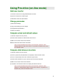
Using Pro-drive (on-line mode) ................................................................................................... 10
Add new inverter...................................................................................................................... 10
Change parameter................................................................................................................... 10
Compare actual and default values ......................................................................................... 10
Compare data between inverters ............................................................................................ 10
Configuring Pro-drive .................................................................................................................. 11
General settings....................................................................................................................... 11
OPC settings............................................................................................................................ 12
Restrictions .............................................................................................................................. 13
Additional settings.................................................................................................................... 13
Create new language............................................................................................................... 14
Appendix ..................................................................................................................................... 15
Keyboard shortcuts.................................................................................................................. 15
Error messages ....................................................................................................................... 16
Internal structure...................................................................................................................... 18
Restrictions .............................................................................................................................. 19
1
Introduction
Overview
Pro-drive is software used for maintenance of Hitachi inverters.
It is a simple, easy-to-use, but also powerful application, capable to communicate with any
inverter type and to access all inverter parameters. Using the internal data base, which contains
limits and dependencies, Pro-drive will not allow user to write any out-of-range value, or to write
some strange combination of parameters which may render inverter unusable.
Inverter parameters are represented in spreadsheet-like form, each row corresponding to a
single parameter. Values are arranged in fields, holding lower and upper range, default value,
user setting and actual (current) setting.
Pro-drive visual interface is highly configurable. User may select which screen elements are
shown, and which columns are shown. Even the order of columns is configurable.
Because of simplicity and safety, Pro-drive may be used not only by engineers and technical
experts, but also by technicians and short-trained persons.
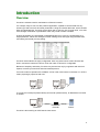
Two main modes of operation are available: on-line mode, with inverter connected, or in off-line
mode, preparing a project for later use.
Pro-drive
Pro-drive
off-line mode
on-line mode
To connect PC serial port (RS232 levels) and inverter (RS422 levels), an RS232/422 converter
is needed.
RS232
Pro-drive
RS232/422
converter
RS422
inverter
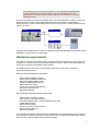
Pro-drive is also working as OPC Data Access Server.
2
OPC stands for "OLE for Process Control". It is a specification standardized
by OPC foundation (www.opcfoundation.org) which enables OPC client
applications to access hardware specific data via OPC servers in a common,
well defined way.
Pro-drive OPC Data Access Server enables OPC clients (SCADA/HMI or other) to connect to
Hitachi inverters, using standard serial RS422 protocol. Visualization or data logging
applications may access inverter parameters in the same way as they usually access working
memory of a PLC.
SCADA
HitOPC
OPC
Pro-drive
Using the internal data base, Pro-drive is handling all limits and dependencies between inverter
parameters, so OPC client is working safe.
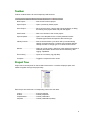
Hardware requirements
Any newly or recently purchased PC easily meets the minimum requirements of Pro-drive. For
an older PC it can be tricky tricky working out whether it can be used or not, but generally any
PC running an approved operating system shall do.
The table below lists the minimum specification required to run Pro-drive, as well as
recommended specification.
Minimum hardware/software requirements:
- CPU Celeron 200MHz or higher
- SVGA monitor (800x600 resolution)
- Microsoft Windows 98SE or later
- 16Mb of available RAM memory
- 4Mb of hard drive space
- mouse or any other pointing device
- serial communication port
- RS232/422 adapter
Recommended hardware/software requirements:
- CPU Pentium III 1GHz or higher
- XGA monitor (1024x768 resolution)
- Microsoft Windows 2000 + latest available service pack
- 512Mb RAM memory
- 4Mb hard drive space
- mouse or any other pointing device
- serial communication port
- RS232/422 adapter
The minimum specification PCs may perform adequately, but it will take a long time to perform
some operations, and may experience some trouble. The recommended specification should
work smoothly, without delays and unnecessary waiting.
3
Concerning the operating system, Pro-drive may be installed on Microsoft Windows 98,
Windows 98 Second Edition, Windows Millennium Edition (Me), Windows 2000, or Windows
XP. Windows 95 and Windows NT4 with Service Pack 4 or greater will work, but may have
some trouble.
The Pro-drive itself requires approximately 4Mb of disk space and about 16Mb or RAM. CPU
load is negligible.
To connect inverter, standard serial communication port (RS232) is required. If no serial port is
available, connection may be established using USB/RS232 converter.
Installation
To install Pro-drive, start the installation archive and follow the instructions.
Installation does the following:
- unpack Pro-drive files into specified directory
- create start menu group and inserts icons
- register Pro-drive OPC server
To uninstall Pro-drive first shut down server (if it is running), then start Control Panel,
Add/Remove Programs, select Pro-drive and press Add/Remove button.
Uninstall procedure removes all installed components and registry entries. User created files,
i.e. configuration data, will not be deleted.
4
User Interface
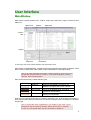
Main Window
Main window consists of Main menu, Toolbar, Project tree, Work area, Legend, Control bar and
Status bar.
Main menu
Toolbar
Work area
Project
tree
Legend
Status bar
Control bar
To turn-off or turn-on a screen element, use main menu View.
Work area is a spreadsheet-like, containing all project properties and inverter parameters. Work
area consists of fields. Each field contain a value, identification or description string.
Hint: to get quick parameter description (without scrolling), place mouse over
the identifier field and wait for a second - a hint window appears, showing
identifier, name and description.
Each work area field may contain different types.
field
type
read-only
read/write
out of range
different
description
read-only field appears if a value is not
allowed to change at the current moment
edit field allows user to enter a new value
field is out of allowed range, and will be
ignored for write operation
appears as a result of a compare operation,
showing not equal fields
Field type may change dynamically, according to parameter type, inverter state (run/stop/error)
and communication state (on-line/off-line), but also according to what is available for a selected
inverter type.
Hint: to change the order of parameters, click a label on top of the column.
parameters may be sorted by identifier, status and function. If compare
function is active, parameters may also be sorted by difference.
5
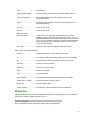
Toolbar
Toolbar contains buttons for most frequently used functions:
New Project..........................Start a new Pro-drive project.
Open Project ........................Open a previously saved project.
Save Project.........................Save current project. If project was not saved before, a dialog
box asking for a project name and path will appear.
Add Inverter..........................Add a new inverter to the current project.
Open template......................Open a new template for the currently selected inverter.
Template type should correspond to the inverter type.
Identify Inverter ....................Start a communication cycle which will try to automatically
identify connected inverter. If inverter type is already defined,
identify will offer to change type or to create a new inverter.
Monitor .................................Open an on-line monitor, used for a quick graphical overview of
selected parameters. Monitor also have a elementary data
logging capabilities.
Error History .........................Open an error history log (trip data).
Compare ..............................Toggle the compare function on/off.
Project Tree
Project tree is vertical panel on the left side of the screen. It contains all project parts, and
makes navigation through the project easy.
Each Project tree node has a corresponding view in the work area.
project...................................project properties
inverter .................................inverter properties
all parameters ......................inverter parameters
template ...............................inverter parameters (subset)
6
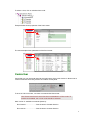
To select a view, click on a desired tree node:
Example below shows properties of the first inverter.
The next example shows parameters of the first inverter.
Control bar
Control bar is a gray horizontal panel at the right bottom of the main window. It allows user to
control inverter the same way as from the inverter control panel.
To show or hide control bar, use menu command View/Control bar.
Hint: Please note that all control functions are disabled in off-line mode. To
make them available, the on-line mode should be selected.
Here is a list of available commands (buttons):
Run forward..........................Start inverter to forward direction.
Run reverse..........................Start inverter to reverse direction.
7
Stop ......................................Stop inverter.
Read actual settings.............Read all inverter parameters to the actual settings column.
Write user settings ...............Write all parameters from user settings column to the
connected inverter.
Store.....................................Execute inverter STORE command. All parameters are now
permanently stored.
On-line..................................Go to on-line mode.
Off-line..................................Go to off-line mode.
Stay connected
to same inverter ...................If this button is not pressed, control bar refers to inverter
selected in project tree. Selecting a different inverter, control
bar disconnects from the current inverter and connects to a new
one. If only one inverter is actually connected, press this button
to stay connected to the connected inverter, no mater which
one is actually selected.
Up, Down .............................Up/down buttons set the requested frequency output.
Here is a list of available indicators:
On-line..................................Display the on-line or off-line status of Pro-drive.
Tx .........................................Transmitting LED, flickers when data is currently transmitted.
Rx .........................................Receiving LED, flickers when data is currently received.
Forward ................................Inverter is running forward.
Reverse ................................Inverter is running reverse.
Stop ......................................Inverter is stopped.
Trip .......................................Inverter is tripped.
Store needed........................A parameter which require store command is changed.
Power off/on needed ............Inverter should be turned off and on.
Comm fail .............................Communication failed.
Comm timeout......................No response - communication timeout encountered.
Status bar
Status bar shows all system error messages and reports. If something goes wrong, status bar
may be very usable to detect where the error is.
For a complete list of error messages, please refer to the appendix.
8
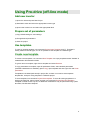
Using Pro-drive (off-line mode)
Add new inverter
1) Open Pro-drive and press New Project
2) Start Add Inverter and select the appropriate inverter type
3) Open Label combo box and select the appropriate label
Prepare set of parameters
1) Copy default settings to user settings
2) Change desired parameters
3) Save the project
Use templates
To open an existing template, use command Project/Open Template (Ctrl-T). Template is
closely related to inverter type, so it is not possible to use template of a different type.
Create new template
To create a new template, use command New Template. An empty template named "Untitled" is
created below All Parameters folder.
To give a name to template, right-click to template and select Rename.
To copy parameters to template, open All parameters folder, select desired parameters
(Ctrl/Shift multiselection is available), press Copy, open template and then right-click and Paste
parameters.
Templates are included (and saved) in project file, so there is no need to save separate
template file, except for using template in a different project.
To save template, use command Project/Save template. To save all existing templates in a
single multi-folder file, select inverter and then use command Project/Save All Templates.
Template is saved as text-only file, so additional modifications may be performed using a plain
text editor, like Windows Notepad.
9
Using Pro-drive (on-line mode)
Add new inverter
1) Connect inverter to PC using RS232/RS422 converter
2) Open Pro-drive and run New Project
3) Start Add Inverter and press Detect
Change parameter
1) Read actual settings
2) Copy actual settings to user settings
3) Change desired parameters
4) Write user settings
Compare actual and default values
1) Activate compare function (Ctrl-Q)
2) Click a small checkbox on default and actual columns
3) Make sure no other columns are selected
Different values are shown with a red outline.
Hint: to show all differences at the top of the window, press the “User
setting” label on the top of the column. To get back to default order, press
the “Identifier” label.
Compare data between inverters
1) Activate compare function (Ctrl-Q)
2) Click on project tree (all parameters or template) to select the left inverter
3) From a compare drop-down menu select the right inverter
4) Click a small checkbox on top of columns which should be compared
5) Make sure no other columns are selected
6) If needed, use horizontal scroll bar to display the desired columns
Hint: to show all differences at the top of the window, press the “User
setting” or “Actual setting” label on the top of the column. To get back to
default order, press the “Identifier” label.
10
Configuring Pro-drive
To change Pro-drive settings, use command Tools/Settings.
Tab "General" refers mainly to appearance, and tab "OPC" refers to the OPC settings.
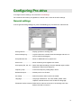
General settings
To show general settings dialog box, press Tools/Setting (F5), and select the “General” tab.
Show grid lines.....................Display grid lines in working area.
Show message log...............Log file is file which contains internal messages and errors. It
may be useful for debugging.
Use production line ..............Show an additional level in project tree.
Show units............................Show measuring units together with values.
Use regions (EU, US, JP) ....Select the regional settings. Only the selected regions will be
displayed in Add Inverter dialog box.
Frequency step ....................Control bar frequency setting step in Hertz.
Default serial port .................Default port for new inverter.
On startup ............................Define first action when Pro-drive is started.
Language .............................Language maintenance. For more details, please check
chapters “Internal structure” and “Create new language”.
Parameter window columns .Define which columns are shown in the working area. Also
defines the order of columns.
11
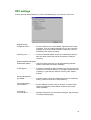
OPC settings
To show general settings dialog box, press Tools/Setting (F5), and select the “OPC” tab.
Register Server
Unregister Server .................Pro-drive OPC server is automatically registered by the setup
procedure. If for any reason registration is lost, this command
registers server to the Windows system without the need for
reinstalling. Also useful for testing.
Show tray icon......................Uncheck to disable taskbar access for unauthorized persons.
Main Pro-drive window may still be accessed by starting if
manually.
Enable UNCERTAIN quality
Enable BAD quality ..............Useful for testing purposes (for developing/testing SCADA
system without real connection available).
Create log file .......................If checked, message log will be written to the file "Pro-drive.log",
created in the Pro-drive directory ("C:\Program Files\Pro-drive\"
is default). Log file may be useful to trace any OPC related
problem.
Quality independent
SyncRead.............................If checked, OPC call SyncIO::Read always returns GOOD tag
quality. Useful for some OPC clients (Wizcon).
Forced OnChange
value updates.......................Forces callbacks to OPC client for all items, no mater if their
value is changed since last callback. Useful for some OPC
clients (RSView).
Show serial
communication .....................Displays and logs all communication messages. May be useful
for testing and debugging.
12
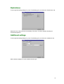
Restrictions
To show general settings dialog box, press Tools/Setting (F5), and select the “Restrictions” tab.
Restrictions are used to limit the functionality of Pro-drive, in order to disallow handling for
unauthorized persons.
Additional settings
To show general settings dialog box, press Tools/Setting (F5), and select the “Additional” tab.
Define default templates for each available inverter type.
13
Create new language
To make a new translation:
1) Use command Tools/Settings/Save to create Custom.lng file. File contains a list of pairs
<id>=<name> (i.e. btnFileNew=New Project). All names are in English (default).
2) Rename Custom.lng to Yourlanguage.lng (i.e. German.lng).
3) Using an UTF-8 text editor, translate all right sides to the appropriate language. Left side
(identifier) should not be modified. String length should about the same length as English
original.
4) Save the translated file (German.lng) in the same directory as Pro-drive.
5) Use Pro-drive command Tools/Settings/Open, confirm and restart Pro-drive.
If for any reason Pro-drive becomes unusable, delete the selected language file and restart Prodrive. To make a complete translation, IDF files should be translated also.
14
Appendix
Keyboard shortcuts
Ctrl-N ....................................New Project
Ctrl-O....................................Open Project
Ctrl-S ....................................Save Project
Shift-Ctrl-S............................Save Project As
Ctrl-F4 ..................................Close Project
Ctrl-P ....................................Print
Ctrl-I......................................Add Inverter
Ctrl-T ....................................Open Template
Ctrl-Q....................................Compare on/off
F5 .........................................Settings
F7 .........................................On-line
F8 .........................................Off-line
F9 .........................................Run Forward
F10 .......................................Run Reverse
F11 .......................................Stop
15
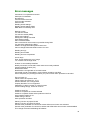
Error messages
Command %s completed successful
Serial port not available
No response
Communication timed out
On-line mode activated...
Off-line mode
Reading actual settings...
Reading actual settings failed
DRW block successfully read
Nothing to write
%s write successful
%s write successful (SRW)
Writing user settings...
Writing user settings canceled
User settings written
Store command failed
Store command on this inverter not possible during RUN
%s cannot be written during RUN
Failed to change RUN state, please check A02
Cannot change RUN state while inverter is in error
Reading error(s)...
Reading errors failed
Reading errors accomplished
Out of range
Error: Some settings are out of range
'%s' contains out of range value:
Inverter %s successfully identified
Identify successful, connected inverter same as currently selected
Could not identify inverter (%s)
Identification failed
Identification not supported on focused inverter
Connected inverter incompatible, communication operation canceled
Source template (%s) and target inverter (%s) not of same class. Operation is canceled
File not found %s
Values cannot be copied to itself
Values cannot be copied %s ! %s
Section identifier '%s' not supported
Property identifier '%s' not supported
Parameter %s does not exist on current inverter
All user settings empty, unable to continue
Unable to open file
Unable to complete: No inverter selected
Unable to complete. Please select production line first
Unsuccessful reading of %s
Failed writing to file %s
Save operation canceled
Warning: Version of project file old
Warning: Version of project file newer
Second motor parameter %s cannot be written while second motor not activated
Second motor parameter %s cannot be written with SRW while second motor mode disabled
This change will reset UserSettings to Defaults
16
Cannot perform this copy operation while Actual Settings not read
Parameter A01 not suitable for this operation
Inverter is on-line. Do you want to proceed?
Only one inverter allowed
Unable to automatically STOP inverter
Warning: "Store needed" pending on some inverters. Do you want to proceed?
Connected inverter does not match to selected
Language will be changed when Pro-drive is restarted
DOP PLUS file contains data for %s which is not compatible with active inverter
Unhandled exception:
17
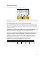
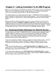
Internal structure
The following picture shows the structure of Pro-drive:
Pro-drive
IDF
LNG
PDT
PDP
Main application, Pro-drive.exe, is using external files of four different types: IDF, LNG, PDT
and PDP. All external files are text-only, making possible to change using a plain text editor,
such as Windows Notepad.
Such structure is used to make Pro-drive as much flexible as it is possible.
IDF (Inverter Definition File) contains knowledge about a specific inverter series, parameters,
addresses, limits, restrictions. IDFs are supplied together with Pro-drive installation package,
but some modified/updated files may be distributed later. IDF may also cover a new software
revision of an inverter.
LNG (language) file contains menus, messages and commands used by Pro-drive user
interface. Each language file contains a single language. To make a localized Pro-drive version,
distributor should make a new language file, which is easy opened by Pro-drive.
PDT (Pro-drive Template) file is a list of selected parameters. Unlike the project file, template
contain no inverters, but contain parameters together with their values/ranges/defaults.
Template may be used to represent a specific usage, i.e. template for a pump or conveyor.
PDP (Pro-drive Project) file is used to store all user data, including inverter parameters,
settings, properties, communication settings and so. To save project file, use command
File/Save Project. To open project file, use command File/Open Project.
Table below summarize external file types and typical scope of usage:
supplied by
Hitachi
local distributor
end user
IDF
+
LNG
+
+
PDT
+
+
+
PDP
+
+
18
Restrictions
Reducing functionality option allows one user ("expert") to prepare sets of parameters, limits,
descriptive names and so (a project) to another user ("user"), including a possibility to disable
some of regular Pro-drive functions, in order to not let him do something wrong.
To prepare a limiting project, expert should:
1. Create a desired project
2. Save project
3. Set functionality limits using text editor
To use the project, user should:
1. Open the project (double click)
Limiting properties reside in [Restrictions] sections. Available properties are:
EnableAllParameters
EnableAllParametersEdit
EnableInverterPropertiesEdit
EnableUserSettingEdit
EnableRangeEdit
EnableDefaultEdit
EnableWriteUserSettings
EnableFileMenu (except Print and exit)
EnableEditMenu
EnableProjectMenu
EnableMonitor
EnableErrorHistory
EnableCompare
EnableSettings
19