1
2–2
Chapter 2: SDRAM Controller Core
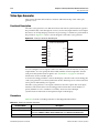
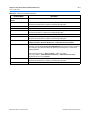
Functional Description
Functional Description
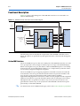
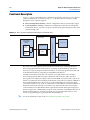
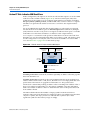
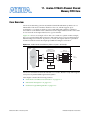
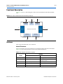
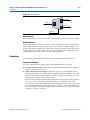
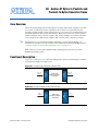
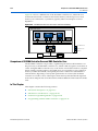
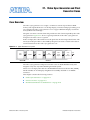
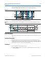
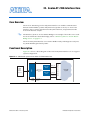
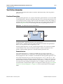
Figure 2–1 shows a block diagram of the SDRAM controller core connected to an
external SDRAM chip.
Figure 2–1. SDRAM Controller with Avalon Interface Block Diagram
Altera FPGA
Clock
Source
SDRAM Clock
PLL
Phase Shift
Controller Clock
Avalon-MM slave
interface
to on-chip
logic
address
data, control
waitrequest
readdatavalid
Control
Logic
SDRAM Chip
(PC100)
Interface to SDRAM pins
clock
Avalon-MM Slave Port
SDRAM Controller Core
clk
cke
addr
ba
cs
cas
ras
we
dq
dqm
The following sections describe the components of the SDRAM controller core in
detail. All options are specified at system generation time, and cannot be changed at
runtime.
Avalon-MM Interface
The Avalon-MM slave port is the user-visible part of the SDRAM controller core. The
slave port presents a flat, contiguous memory space as large as the SDRAM chip(s).
When accessing the slave port, the details of the PC100 SDRAM protocol are entirely
transparent. The Avalon-MM interface behaves as a simple memory interface. There
are no memory-mapped configuration registers.
The Avalon-MM slave port supports peripheral-controlled wait states for read and
write transfers. The slave port stalls the transfer until it can present valid data. The
slave port also supports read transfers with variable latency, enabling
high-bandwidth, pipelined read transfers. When a master peripheral reads sequential
addresses from the slave port, the first data returns after an initial period of latency.
Subsequent reads can produce new data every clock cycle. However, data is not
guaranteed to return every clock cycle, because the SDRAM controller must pause
periodically to refresh the SDRAM.
f
For details about Avalon-MM transfer types, refer to the Avalon Interface Specifications.
Embedded Peripherals IP User Guide
© December 2010 Altera Corporation