1
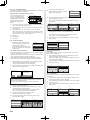
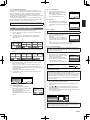
6.4.7. I.U. Address Verification
6.4.9. Installer Password Change
Check the address and position of the indoor unit.
Change the Installer password.
1.
Touch the [I.U. Address Verification] on the “Maintenance” screen.
The “I.U. Address Verification” screen is displayed.
If there are multiple pages, you can switch between them by touching
[Next Page] or [Previous Page].
Touch [Check] to display the indoor unit address checking start
screen.
1. Touch the [Installer Password Change] on the “Maintenance” screen.
The “Installer Password Verification” screen is displayed.
Enter the current password, then touch the [OK].
The default password is “0000” (4 digits).
2. The “Installer Password Change” screen is displayed.
Enter the new password, then touch the [OK]. It returns to the
“Maintenance” screen.
2. Touch [Yes] to display the confirmation screen.
1.
3. Select the indoor unit to be checked. If there are multiple pages,
you can switch between them by touching [Next Page] or [Previous
Page]. The selected indoor unit will start to blow air and flash a LED*.
(*Only when the indoor unit has the relevant functions)
Touch [Back] on the confirmation screen to return to the previous
screen.
1.
2.
I.U. Address Verification
No.
1
2
3
4
5
6
System–Unit
002–1
002–2
002–3
002–4
002–5
002–6
/
/
/
/
/
/
/
Indoor unit position will be checked. OK?
Next
Page
Back
Check
No
System–Unit
Page 1/ 2
/ 01–01
2 002–2
/ 01–02
3 002–3
/ 01–03
No.
1
2
3
4
5
6
System–Unit
002–1
002–2
002–3
002–4
002–5
002–6
/
/
/
/
/
/
/
Check
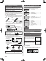
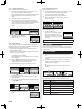
6.4.8. Function Setting
This procedure changes the function settings used to control the indoor unit
according to the installation conditions. Incorrect settings can cause the
indoor unit to malfunction. Perform the “Function Setting” according to the
installation conditions using the remote controller.
• Refer to the indoor unit installation manual for details on the function
numbers and setting numbers.
• Prepare for setting of indoor unit referring to installation manual of indoor
unit before start of functional setting.
“Function Setting” screen is displayed.
Touch the [Address] on the “Function Setting” screen. The “Address”
screen is displayed.
2. Touch [ ] or [ ] to select the address of the indoor units to be
Function No.
[00]
Setting No.
Back
Address
Cancel
[002–1]
Function No.
OK
Back
0
1
2
3
4
5
6
7
8
9
Cancel
OK
[00]
1. If an error occurred, an error icon appears on the “Monitor mode
screen”.
Touch the [Status] on the “Monitor mode screen”. The “Status” screen
is displayed.
1.
2.
Fri 10:00AM
3.
Mode
Set Temp.
Fan
Status
Page 1/ 3
Air Flow Direction
VT
Setting
“Function Setting” screen.
6.
Address
Cancel
OK
Function Setting
[002–1]
Function No.
[00]
Setting No.
Setting No.
[00]
00
Back
Setting
7. Touch [Back] to return to the “Maintenance”
screen.
Cancel
OK
[002–1]
[00]
Setting No.
[00]
Setting
14,15, 41, 44
Monitor
Off
Next
Page
Error code
Error
Information
Back
Next
Page
Contents
CC.1
Sensor error
C2.1
Transmission PCB error
12.1
Wired remote controller communication error
12.3
Number excess of device in wired remote controller
system
29.2
Connection unit number error (Remote controller)
26.4
Address duplication in wired remote controller system
26.5
Address setting error in wired remote controller system
15.4
Data acquisition error
[00]
Function No.
Back
En-8
[002–01]
Function Setting
Address
Error Code
3
For the details of the indoor unit or outdoor unit error when checking the
error contents, refer to the error codes in each installation manual.
6. Touch [ ] or [ ] to set the setting number. Touch [OK] to return to the
00
Menu
Page 1/ 5
02-01
Anti Freeze
Off
Status
Error Information
Address
HZ
1
screen is displayed.
Address
Function No.
OK
[00]
5. Touch the [Setting] on the “Function Setting” screen. The “Setting”
5.
Cancel
8. ERROR CODES
the “Function Setting” screen.
Function Setting
Remote controller will be initialized
to the factory default setting. OK?
For how to carry out a test run, refer to 6. 4. Maintenance (Other Settings)
→ 6.4.5. Test Run.
4. Touch [ ] or [ ] to set the function number. Touch [OK] to return to
Function No.
Initialization
7. TEST RUN
Economy
4.
OK
below.
Touch the [Next page] (or [Previous page]) to switch to other unit
information.
Setting No.
Setting
CL
• Test run method of the indoor unit is explained.
• Refer to the indoor unit installation manual for the list of items to check.
Function Setting
[00]
9
When relocating the set remote controller, initialize it.
3.
002–01
8
3. 2-digit numbers are corresponding to the error code in the table
“Function No.” screen is displayed.
All
7
Information” screen is displayed. (If there are no errors, the [Error
Information] will not be displayed.)
3. Touch the [Function No.] on the “Function Setting” screen. The
Address
6
2. Touch the [Error Information] on the “Status” screen. The “Error
configured. (To set all indoor units at the same time, touch [All].)
Touch [OK] to return to the Function Setting screen.
[002–1]
5
Check the error
1. Touch the [Function Setting] on the “Maintenance” screen. The
Address
4
“Maintenance” screen. Enter the Installer
password. The “Initialization” screen is
displayed.
When the [OK] is touched, this unit restarts
automatically after initialization. Perform
each setting.
Page 1/ 2
Ref.–In.
01–01
01–02
01–03
01–04
01–05
01–06
Next
Page
Back
Function Setting
3
6.4.10. Initialization
Next
Page
I.U. Address Verification
2.
2
1. Touch the [Initialization] on the
End
Verification Screen” to return to the
Maintenance Screen.
1
Require an Installer password.
/ Ref.–In.
1 002–1
Yes
4. Touch [Back] on the “IU Address
1.
CL
0
Cancel
I.U. Address Verification
No.
Enter New Password
Enter Current Password
3.
I.U. Address Verification
Page 1/ 2
Ref.–In.
01–01
01–02
01–03
01–04
01–05
01–06
2.
Installer Password Change
Installer Password Verification