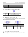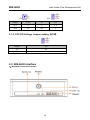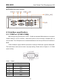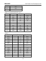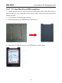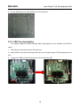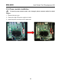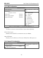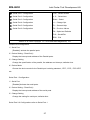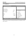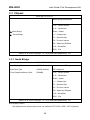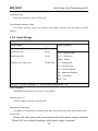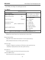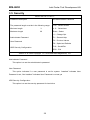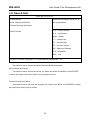
1
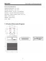
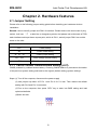
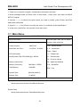
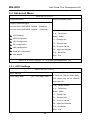
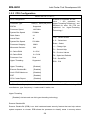
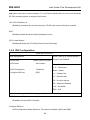
BIS-6630
BOX PC System
Manual V1.1
BIS-6630
Intel Cedar Trail Development Kit
Disclaimer
Norco BIS-6630 Box PC System User Manual Rev 1.1 (March 2012)
We reserve the right to make changes, without notice, to any product, including circuits and/or
software described or contained in this guide in order to improve design and/or performance.
We assume no responsibility or liability for the use of the described product(s) conveys no
license or title under any patent, copyright, or masks work rights to these products, and make no
representations or warranties that these products are free from patent, copyright, or mask work
right infringement, unless otherwise specified. Applications that are described in this guide are
for illustration purposes only. We Shenzhen Norco Intelligent Technology Co make no
representation or warranty that such application will be suitable for the specified use without
further testing or modification.
1
BIS-6630
Intel Cedar Trail Development Kit
Table of Contents
Preface.................................................................................................................................... 4
Checklist ....................................................................................................................... 4
Copyright Notice ........................................................................................................... 4
About this Manual ......................................................................................................... 4
Chapter 1. Product Introduction ............................................................................................... 5
1.1 Overview ................................................................................................................. 5
1.2 Specification............................................................................................................ 5
1.3 Product Dimension Diagram.................................................................................... 7
Chapter 2. Hardware features.................................................................................................. 8
2.1 Jumper Setting ........................................................................................................ 8
2.1.1 CMOS Content Clearance/Hold Setting (JCC) ........................................ 8
2.1.2 Start Upon Power-on Hardware Switch (JAT) .......................................... 9
2.1.3 COM2 Jumper Setting(J5,J6,J8) ..................................................... 9
2.4.4 LVDS Voltage Jumper Setting(JP1、JP2) ............................................ 9
2.4.5 PCI VIO Voltage Jumper setting(JP5)................................................. 10
2.2 BIS-6630 Interface ............................................................................................... 10
2.3 Interface specification............................................................................................ 11
2.3.1 COM Port(COM1-COM6) .................................................................... 11
2.3.2 Display Interface(VGA、DVI) .............................................................. 13
2.3.3 USB Ports(USB_12、USB_34、USB_56).......................................... 14
2.3.4 Network Interface(LAN1、LAN2) ........................................................ 14
2.3.5 Audio Interface......................................................................................... 15
2.3.6 Power Button ........................................................................................... 15
2.3.7 Reset ....................................................................................................... 15
2.4 Internal Interface ................................................................................................... 15
2.4.1 SATA Interface ........................................................................................ 15
2.4.2 SO-DIMM Slot ......................................................................................... 16
2.4.4 MINI PCIe slot(MINI PCIe1,MINI PCIe2,J3,J4) ........................... 16
2.5 Hardware Installation............................................................................................. 16
2
BIS-6630
Intel Cedar Trail Development Kit
2.5.1 DDRIII SO-DIMM RAM Installation .......................................................... 16
2.5.2 2.5” Hard Disk Drive (HDD) Installation ................................................. 17
2.5.3 SSD Card Installation .............................................................................. 18
2.5.4 Power module installation ........................................................................ 19
Chapter3. BIOS Setup ........................................................................................................... 20
AMI BIOS Upgrading................................................................................................... 20
AMI BIOS Description ................................................................................................. 20
BIOS Parameter Configuration: ................................................................................ 20
3.1 Main Menu ........................................................................................................... 21
3.2 Advanced Menu ................................................................................................... 22
3.2.1 ACPI Settings ......................................................................................... 22
3.2.2 APM Configuration .................................................................................. 23
3.2.3 CPU Configuration .................................................................................. 24
3.2.4 IDE Configuration.................................................................................... 25
3.2.5 USB Configuration .................................................................................. 26
3.2.6 Supper IO Configuration ......................................................................... 26
3.2.7 H/W Monitor ............................................................................................ 28
3.3 Chipset ................................................................................................................. 29
3.3.1 North Bridge............................................................................................ 29
3.3.2 South Bridge ........................................................................................... 30
3.4 Boot ..................................................................................................................... 31
3.5 Security ................................................................................................................ 32
3.6 Save & Exit........................................................................................................... 33
Appendix ............................................................................................................................... 34
Appendix 1: Watchdog Programming Guide ................................................................ 34
Appendix 2: User Guide for Fedora14 ......................................................................... 35
Appendix 3: Glossary .................................................................................................. 41
3
BIS-6630
Intel Cedar Trail Development Kit
Preface
Checklist
Thanks for choosing BIS-6630 from an acknowledged leader in the industry. Norco systems
are designed with the utmost attention to detail and to provide you with the highest standards in
quality and performance.
Please check that the following items which have all been included with your system. If
anything listed here is damaged or missing, contact your retailer.
●BIS-6630
●CD-ROM(Drivers and User Manual)
●Power Adapter and Power Cord
Copyright Notice
ALL RIGHTS RESERVED. No part of this document may be reproduced, copied, translated, or
transmitted in any form or by any means, electronic or mechanical, for any purpose, without the
prior written permission of the original manufacturer.
About this Manual
This manual provides information for installation and use of Norco BIS-6630 system. Norco
highly recommends reading this Manual to familiarize yourself with the setup procedure before
installing your system.
4
BIS-6630
Intel Cedar Trail Development Kit
Chapter 1. Product Introduction
1.1 Overview
BIS-6630 is a type of embedded system developed around Intel® Cedar Trail with Intel® NM
10 chipset and Intel® Atom N2800/D2550 processor. It supports single slot DDRIII 1066
SO-DIMM RAM up to 4GB. The system provides 2 SATA ports, 2 Gigabit Ethernet ports and
VGA, LVDS and DVI display ports. 6 USBs and 6 serial ports are used for data transfer. The
system also supports Line-out, Line-in, Mic-in and 1 PCI, 2 Mini PCIe and SIM slot on board.
1.2 Specification
Motherboard Form Factor
●Standard Mini-ITX
Processor
●On board Intel ® Atom N2800/D2550 Processor
Chipset
●Intel®NM10
Display
●Video Controller:Processor Integrated
●VGA:1 standard DB15 port,resolution up to1920×1200@60Hz
●DVI:1 standard DVI-D, supports HDMI,resolution up to1920×1200@60Hz
Memory
●Single slot SO-DIMM DDR III 1066, up to 4GB
Storage
●2 standard 7 Pin SATA ports
LAN
●Ethernet Controller: 82574L network chip
●2 standard RJ45 port
5
BIS-6630
Intel Cedar Trail Development Kit
●Wake on LAN
●PXE boot
●Speed:10/100/1000Mbps
Audio
●Audio Controller ALC887 7.1 HD chip
●Rear panel: Line-in(Blue), Speak-out(Green), Mic-in(Red)
●Front panel: Speak-out,Mic-in
USB
●Rear panel: 4 standard USB
●front panel: 2 standard USB
I/O
●Controller: ITE 8783F I/O Chip
●COM1-2: stand DB9 ports
●COM3-6: 2×20 internal Pin header
●COM1-COM6 supports RS232,COM2 also supports RS422\485
Expansion
●2 MINI PCIe,
MINI PCIe 1: standard MINI PCIe; MINI PCIe 2: optional for WiFi,3G,SDD
Power Supply
●System power:DC +12V@5A
●RTC Battery:3V/220 mAh
WatchDog program
●Hardware reset function
BIOS
●2MB SPI BIOS
6
BIS-6630
Intel Cedar Trail Development Kit
Environment & Mechanical
●Operating Temperature:0℃~60℃
●Storage Temperature:-40℃~85℃
●Relative Humidity:5%~95%,non-condensing
●Vibration:0.5g rms/5~500Hz/random operating
●Dimension:190mm×190mm×67mm(W×L×H)
●EMC:CE/FCC Class B
●Material:Aluminum Ally
●Color:Black
1.3 Product Dimension Diagram
7
BIS-6630
Intel Cedar Trail Development Kit
Chapter 2. Hardware features
2.1 Jumper Setting
Please refer to the following jumper setting guide before installing your hardware devices
installation.
Remark: How to identify jumper and PIN1 of interface: Please observe the word mark of plug
socket, it will use “1” or bold line or triangular symbols; And please look at the back of PCB,
each interface weld spot has a square point, which is PIN 1; and all jumper PIN1 has a white
arrow on the side.
Jumper Reference
JCC
COMS setting
JAT
Power mode setting
J5,J6,J8
COM2 jumper setting
JP1、JP2
LVDS voltage jumper setting
JP5
PCI VIO voltage jumper setting
2.1.1 CMOS Content Clearance/Hold Setting (JCC)
CMOS powered by onboard button battery. Cleaning CMOS leads to a permanent elimination
of the previous system setting and back to the original (default setting) system settings.
Steps:(1) Turn off the computer, disconnect the power supply
(2) Use jumper cap short JCC Pin 1 and Pin 2 for 5~6 sec. Then restore the default
setting with Pin2 and Pin 3 connected;
(3)Turn on the computer, then press “DEL” key to enter into BIOS setting and load
optimized defaults.
(4)Save and exit.
8
BIS-6630
Intel Cedar Trail Development Kit
JCC:
Jumper
JCC
1-2
Clear CMOS, BIOS renew to initialization (default setting)
2-3
Normal Status (default)
Do not clear CMOS when computer is running, it will damage the motherboard
2.1.2 Start Upon Power-on Hardware Switch (JAT)
Jumper
JAT
Open
Non self-start upon power on (ATX)
Close
Self-start upon power on (AT)
2.1.3 COM2 Jumper Setting(J5,J6,J8)
J5,J6,J8 are used to configure transmission mode for COM2,COM2 supports RS 232/RS
422/RS 485,default transmission mode is RS 232。
J5、J6
COM2
J8
RS232(default)
COM2
RS422
COM2
RS485
J5
1-3
2-4
J5
3-5
4-6
J5
3-5
4-6
J6
1-3
2-4
J6
3-5
4-6
J6
3-5
4-6
J8
5-6
7-8
J8
1-2
J8
3-4
2.1.4 LVDS Voltage Jumper Setting(JP1、JP2)
: Wrong voltage selection may damage the LVDS panel. Please survey LVDS panel’s
voltage before setup this jumper setting.
9
BIS-6630
Intel Cedar Trail Development Kit
JP1
JP2
Jumper
3.3V
5V
12V
JP1
×
×
1-2
JP2
1-2
2-3
×
2.1.5 PCI VIO Voltage Jumper setting(JP5)
Jumper
JP5
1-2
5V
2-3
3.3V
2.2 BIS-6630 Interface
1)BIS-6630 Front Panel Interface
10
BIS-6630
Intel Cedar Trail Development Kit
2)BIS-6630 Rear panel interface
2.3 Interface specification
2.3.1 COM Port(COM1-COM6)
BIS-6630 provides 6 serial ports. COM1、COM2 are standard DB9 interface on rear panel.
COM3-6 adopt 2×20 Pin interface,these serial ports can be converted to standard port via
convert cable. The COM ports can be enable/disabled and set interrupt IRQ and I/O address in
BIOS.
COM1-COM6 all support RS232 transmission mode and COM2 also supports RS422/485.
The transmission mode can be chosen via jumper setting. Please refer to Chapter 2.1.3 “COM2
jumper setting”
COM1、COM2:
Pin
Signal Name
1
DCD
2
RXD
3
TXD
4
DTR
5
GND
6
DSR
11
BIS-6630
Intel Cedar Trail Development Kit
7
RTS
8
CTS
9
RI
COM2 is on RS232/RS422/RS485 mode:
Pin
RS232(Default)
RS422
RS485
1
DCD
TX-
DATA-
2
DSR
NC
NC
3
RXD
TX+
DATA+
4
RTS
NC
NC
5
TXD
RX+
NC
6
CTS
NC
NC
7
DTR
RX-
NC
8
RI
NC
NC
9
GND
GND
GND
10
GND
GND
GND
COM3-6:
Signal
Pin
Signal Name
DCD3
1
2
DSR3
RXD3
3
4
RTS3
TXD3
5
6
CTS3
DTR3
7
8
RI3
GND
9
10
GND
DCD4
11
12
DSR4
RXD4
13
14
RTS4
TXD4
15
16
CTS4
DTR4
17
18
RI4
GND
19
20
GND
DCD5
21
22
DSR5
RXD5
23
24
RTS5
TXD5
25
26
CTS5
12
BIS-6630
Intel Cedar Trail Development Kit
DTR5
27
28
RI5
GND
29
30
GND
DCD6
31
32
DSR3
RXD6
33
34
RTS6
TXD6
35
36
CTS6
DTR6
37
38
RI6
GND
39
40
GND
2.3.2 Display Interface(VGA、DVI)
VGA
DVI
VGA:
Pin
Signal Name
Pin
Signal Name
Pin
Signal Name
1
RED
6
GND
11
NC
2
GREEN
7
GND
12
SDA
3
BLUE
8
GND
13
HSYNC
4
NC
9
+5V
14
VSYNC
5
GND
10
GND
15
SLK
DVI
Signal Name
Pin
Signal Name
TDC2#
1
2
TDC2
GND
3
4
NC
NC
5
6
SC-DDC
SD-DDC
7
8
NC
TDC1#
9
10
TDC1
GND
11
12
NC
NC
13
14
VCC
GND
15
16
HP-DETECT
TDC0#
17
18
TDC0
GND
19
20
NC
13
BIS-6630
Intel Cedar Trail Development Kit
NC
21
22
GND
TLC
23
24
TLC#
GND
25
26
GND
NC
27
28
NC
2.3.3 USB Ports(USB_12、USB_34、USB_56)
USB:
Pin
Signal name
1
+5V
2
USB DATA-
3
USB DATA+
4
GND
2.3.4 Network Interface(LAN1、LAN2)
System provides two RJ 45 standard Ethernet ports. The yellow LED indicates the status
of data transmission and the green one indicates network connection status.
RJ45 PORT LED 状态描述:
LI LED(Green)
Function
ACT LED(Yellow)
Function
ON
Effective
ON
Data transmitting
OFF
Ineffective/Close
OFF
No Data
14
BIS-6630
Intel Cedar Trail Development Kit
2.3.5 Audio Interface
System provides one Speak-out,one Mic-in on the front panel and provides one group
triple-layer Audio interface: Line-in (Blue), Speak-out (Green), Mic-in(Pink).
Front Panel
Rear Panel
2.3.6 Power Button
Power and HDD LED indicator are on the power button. Power LED is blue and HDD
LEDis red. Power button keep blue light if no HDD movement. If HDD is running, the red HDD
LED keep blinking
2.3.7 Reset
BIS-6630 system will be hardware reset when the power button is pushed
2.4 Internal Interface
2.4.1 SATA Interface
BIS-6630 provides two standard 7 pin SATA interface.
SATA:
Pin
Signal Name
1
GND
2
TX+
3
TX-
4
GND
5
RX-
6
RX+
7
GND
15
BIS-6630
Intel Cedar Trail Development Kit
2.4.2 SO-DIMM Slot
204Pin DDRⅢ SO-DIMM Slot supports DDRⅢ 1066 which can support up to 4GB.
2.4.4 MINI PCIe slot(MINI PCIe1,MINI PCIe2,J3,J4)
The system provides two MINI PCIe slot,MINI PCIe 1 is standard Mini-PCIE, MINI PCIe 2
support WiFi、3G or SSD. When wifi is used for MINI PCIe 2 slot, J3 and J4 can be used for
internet status indicator.
J3、J4:
Pin
Signal Name
1
ACT-
2
ACT+
2.5 Hardware Installation
2.5.1 DDRIII SO-DIMM RAM Installation
BIS-6630 provides one SO-DIMM Socket,supports DDRIII 1066 up to 4GB RAM. Please
follow these steps below carefully to install:
1.Twist off the screws and remove the top cover
2.
Insert RAM into slot and make sure the gold finger of RAM aligning with the slot.
3. Press down the RAM slowly unit you hear “Click”.
16
BIS-6630
Intel Cedar Trail Development Kit
2.5.2 2.5” Hard Disk Drive (HDD) Installation
System provides one 2.5” HDD bay and two SATAII ports inside. (when MINI PCIe2 is
used for SSD, only one STATII port can be used for HDD). lease follow these steps below
carefully to install:
1:
Turn off Power, remove the power line first.
2:Twist off the screws of the HDD Bay cover and remove it.
3:Choose the 2.5” HDD and mount it on the HDD Bay cover with screws.
17
BIS-6630
Intel Cedar Trail Development Kit
4.Put the HDD Bay cover with HDD back to the computer.
2.5.3 SSD Card Installation
The system supports mSATA standard SSD (3G expansion is not available once SSD is
used).
1.Twist off the screws and remove the top cover.
2.Insert SDD into slot with lean angel and make sure the gold finger of SSD aligning with the
slot.
3.
Slowly push SSD into the slot and secure two screws for SSD
18
BIS-6630
Intel Cedar Trail Development Kit
2.5.4 Power module installation
If internal power module need to be changed, please contact retailer for detail
support
1.Remove the top cover.
2.Choose the right ATX power module to install.
3.Insert the power connector to ATX power slot.
19
BIS-6630
Intel Cedar Trail Development Kit
Chapter3. BIOS Setup
AMI BIOS Upgrading
BIOS functions as a bridge connecting hardware and operating system. Hardware and
software are upgrading all the time, so when your system goes wrong, for example, your
system can not support the newest CPU, you need to upgrade BIOS to keep up with the latest
technology.
To make the BIOS upgrade successfully, please open the Jumper JAV. AFUDOS.EXE is the
FLASH IC program for BIOS to upgrade, which needs to be run in DOS mode. Use a boot disk
to load DOS, then run AFUDOS.EXE to upgrade BIOS.
Upgrade Command:
A:\ Afudos “ROM NAME”.rom
If you need to add other parameters, add “space” after the Command.
Example:Afudos 3870T101.rom /P /B /C /N /X
Remarks:
1. BIOS upgrading is only executed when your system goes wrong.
2. Please use the upgrade program in the CD-ROM provided by us or download the latest
version on our website
3. Please do not power off or reboot the system when upgrading, otherwise, the BIOS will be
damaged and system is not able to boot again.
4. Please backup your BIOS before upgrading
AMI BIOS Description
When the computer is power on, BIOS will conduct self-diagnosis to its hardware on
motherboard and configure hardware parameter; finally the operating system will take control.
BIOS is the communication bridge between hardware and O/S. Correct configuration of BIOS
is critical for maintaining system stability.
BIOS Parameter Configuration:
20
BIS-6630
Intel Cedar Trail Development Kit
1.Power on or reset the computer, self-detection information will show:
2.When message shows as "Press <Del> to enter setup",Press <Del>, then enter into BIOS
SETUP Program.
3.Use the “←↑→↓”to choose the option which your want to modify, press <Enter> and the
sub-menu will show.
4.Use the “←↑→↓”and <Enter> to modify the value, or use Mouse do this Modification.
5.At any time, press<Esc> can go back to the main menu.
3.1 Main Menu
BIOS SETUP UTILITY
Set the Date. Use Tab to switch
BIOS Information
between Date elements.
BIOS Vendor
American Megatrends
Project Version
6930T109
→←:Select Screen
Build Date and Time
11/15/2011 10:38:49
↑↓:Select Item
Enter:Select
CPU Information
+/-:Change Opt.
Intel(R) Atom(TM) CPU N2800 @ 1.86GHz
F1:General Help
F2:Previous Values
Memory Information
Memory Frequency
F9:Optimized Defaults
1066 MHz(DDR3)
Total Memory
2048 MB
System Date
[Mon 08/29/2011]
System Time
[11:08:24]
F10:Save&Exit
ESC:Exit
Version 2.10.1208. Copyright(C)2010 American Megatrends,Inc.
System Time
Setup system time format: Hour/Minute/ Second
System Date
Setup system date format: Week/Month/Day/Year
21
BIS-6630
Intel Cedar Trail Development Kit
3.2 Advanced Menu
BIOS SETUP UTILITY
Monitor hardware status.
BIOS Information
Legacy OpROM Support
Launch LAN1 (82574)PXE OpROM
Launch LAN2 (82574)PXE OpROM
[Disabled]
[Disabled]
→←:Select Screen
↑↓:Select Item
ACPI Settings
Enter:Select
APM Configuration
+/-:Change Opt.
CPU Configuration
F1:General Help
IDE Configuration
F2:Previous Values
USB Configuration
F9:Optimized Defaults
Super IO Configuration
F10:Save&Exit
H/W Monitor
ESC:Exit
Version 2.10.1208. Copyright(C)2010 American Megatrends,Inc.
3.2.1 ACPI Settings
BIOS SETUP UTILITY
Enables or Disables System ability
ACPI Settings
ACPI Sleep State
[S1(CPU Stop Clock)]
to Hibernate (OS/S4 Sleep State).
This option may be not effective
with some OS..
→←:Select Screen
↑↓:Select Item
Enter:Select
+/-:Change Opt.
F1:General Help
F2:Previous Values
F9:Optimized Defaults
F10:Save&Exit
ESC:Exit
22
BIS-6630
Intel Cedar Trail Development Kit
ACPI Sleep State
Sleep mode selection: Different modes are defined with different power consumption.
S1 (POS): CPU stops working while other devices are still connected to power supply.
S3 (STR): Power is only supplied to system memory.
3.2.2 APM Configuration
BIOS SETUP UTILITY
RTC Power On Function
[Disabled]
Enable or disable System wake on
alarm event. When enabled.
System will wake on the
hr::min::sec specified
→←:Select Screen
↑↓:Select Item
Enter:Select
+/-:Change Opt.
F1:General Help
F2:Previous Values
F9:Optimized Defaults
F10:Save&Exit
ESC:Exit
Version 2.10.1208. Copyright(C)2010 American Megatrends,Inc.
RTC Power On Function
It is used for waking system on alarm event
23
BIS-6630
Intel Cedar Trail Development Kit
3.2.3 CPU Configuration
BIOS SETUP UTILITY
CPU Configuration
Processor Type
EMT64
Intel(R)
Atom(TM) CPU
Supported
Processor Speed
1865 MHz
System Bus Speed
533MHz
Ratio Status
14
Actual Ratio
14
System Bus Speed
533 MHz
Processor Stepping
30661
Microcode Revision
262
L1 Cache RAM
2×56 K
L2 Cache RAM
2×512 K
Processor Core
Dual
Hyper-Threading
Supported
Hyper-Threading
[Enabled]
Execute Disabled Bit
[Enabled]
Limit CPUID Maximum
[Disabled]
EIST
[Enabled]
CPU C state Report
[Enabled]
Enabled for Windows XP and
Linux ( OS optimized for
Hyper-Threading Technology)and
Disabled for other OS ( OS not
optimized for Hyper-Threading
Technology).
→←:Select Screen
↑↓:Select Item
Enter:Select
+/-:Change Opt.
F1:General Help
F2:Previous Values
F9:Optimized Defaults
F10:Save&Exit
ESC:Exit
Version 2.10.1208. Copyright(C)2010 American Megatrends,Inc.
This Read-Only option contains the detailed information of CPU, including CPU
manufacturer, type, frequency, L1 cache and L2 cache, etc.
Hyper-Threading
[Enabled]: Activate and use this hyper threading technology.
Execute Disabled Bit
Execute Disable Bit (EDB) is an Intel hardware-based security feature that can help reduce
system exposure to viruses. EDB allows the processor to classify areas in memory where
24
BIS-6630
Intel Cedar Trail Development Kit
application code can or cannot execute. To use Execute Disable Bit you must have Windows
XP SP2 operating system to support this function.
Limit CPU ID Maximum
[Enabled]: processor will limit the maximum CPUID input value to 03h when queried.
EIST
[Enable] Activate Enhanced Intel Speedstep function
CPU C state Report
[Enabled] Activate the CPU Deep Power Down Technology
3.2.4 IDE Configuration
BIOS SETUP UTILITY
SATA Ports (0-3) Device Names if
IDE Configuration
SATA Porto
Hitachi HDS721(1000)
SATA Port1
Not Present
SATA Controller(s)
[Enabled]
Present and Enabled.
→←:Select Screen
↑↓:Select Item
Enter:Select
Configure SATA as
[IDE]
+/-:Change Opt.
F1:General Help
F2:Previous Values
F9:Optimized Defaults
F10:Save&Exit
ESC:Exit
Version 2.10.1208. Copyright(C)2010 American Megatrends,Inc.
SATA Controller(S)
[Enabled]: Activate SATA Controller.
Configure SATA as
SATA Configuration Model Selection. Two options available: [AHCI] and [IDE].
25
BIS-6630
Intel Cedar Trail Development Kit
3.2.5 USB Configuration
BIOS SETUP UTILITY
Select USB mode to control USB
USB Configuration
ports.
USB Devices:
→←:Select Screen
1 Keyboard ,1 Mouse
USB function
[Enabled]
↑↓:Select Item
USB 2.0 (EHCI) Support
[Enabled]
Enter:Select
Legacy USB Support
[Enabled]
+/-:Change Opt.
F1:General Help
F2:Previous Values
F9:Optimized Defaults
F10:Save&Exit
ESC:Exit
Version 2.10.1208. Copyright(C)2010 American Megatrends,Inc.
USB function
This option is to set open or close the USB port. System defaults as[Enabled]
USB 2.0 (EHCI) Support
[Enabled]: Activate USB EHCI, max transmission rate up to 480Mpbs
Legacy USB Support
[Enabled]: Active the USB device in DOS mode: USB flash Disk, USB keyboard, etc.
3.2.6 Supper IO Configuration
BIOS SETUP UTILITY
Set Parameters of Serial Port 1
Super IO Information
Super IO Chip
IT8783F
Parallel Port Configuration
26
(COMA)
BIS-6630
Intel Cedar Trail Development Kit
Serial Port 1 Configuration
→←:Select Screen
Serial Port 2 Configuration
↑↓:Select Item
Serial Port 3 Configuration
Enter:Select
Serial Port 4 Configuration
+/-:Change Opt.
Serial Port 5 Configuration
F1:General Help
Serial Port 6 Configuration
F2:Previous Values
F9:Optimized Defaults
F10:Save&Exit
ESC:Exit
Version 2.10.1208. Copyright(C)2010 American Megatrends,Inc.
Parallel Port Configuration
1)Serial Port
[Enabled]: activate the parallel ports
2)Device Setting(Read Only)
Display the interrupt and address of the Parallel ports.
3)Change Setting
Change the specification of the parallel, like address and interrupt, defaults Auto.
4)Device Mode
Choose the device mode for the Parallel port including standard,EPP,ECP,ECP+EPP
etc.
Serial Port 1 Configuration
1)Serial Port
[Enabled] Activate the serial ports.
2)Device Setting(Read Only)
Display the interrupt and address of the serial ports.
3)Change Setting
Change the setting for serial port, defaults Auto
Serial Port 2-6 Configurations refer to Serial Port 1.
27
BIS-6630
Intel Cedar Trail Development Kit
3.2.7 H/W Monitor
BIOS SETUP UTILITY
PC Health Status
System temperature
: + 46℃
→←:Select Screen
CPU temperature
: +53℃
↑↓:Select Item
CPU Fan Speed
: N/A
Enter:Select
+/-:Change Opt.
VCore
: +1.061V
F1:General Help
+3.3V
: +3.316V
F2:Previous Values
+5V
: +4.909V
F9:Optimized Defaults
F10:Save&Exit
ESC:Exit
Version 2.10.1208. Copyright(C)2010 American Megatrends,Inc.
PC Health Status
Display the status of the system including system temperature, CPU temperature, CPU Fan
Speed, Voltage etc.
28
BIS-6630
Intel Cedar Trail Development Kit
3.3 Chipset
BIOS SETUP UTILITY
North Bridge Parameters
→←:Select Screen
↑↓:Select Item
Enter:Select
North Bridge
+/-:Change Opt.
South Bridge
F1:General Help
F2:Previous Values
F9:Optimized Defaults
F10:Save&Exit
ESC:Exit
Version 2.10.1208. Copyright(C)2010 American Megatrends,Inc.
3.3.1 North Bridge
BIOS SETUP UTILITY
Boot Display Device
[VBIOS Default]
Auto disable IGD upon external
Flat Panel Type
[VBIOS Default]
GFX detected.
Fixed Graphics Memory Size
[256MB]
→←:Select Screen
↑↓:Select Item
Enter:Select
+/-:Change Opt.
F1:General Help
F2:Previous Values
F9:Optimized Defaults
F10:Save&Exit
ESC:Exit
Version 2.10.1208. Copyright(C)2010 American Megatrends,Inc.
Boot Display Device
Set display device when system boots up, defaults CRT, LVDS, LVDS+ CRT is optional.
29
BIS-6630
Intel Cedar Trail Development Kit
Flat Panel Type
Select the resolution under LVDS mode.
Fixed Graphics Memory Size
Fix shared memory; driver will distribute the system memory size according to BIOS
setting
3.3.2 South Bridge
BIOS SETUP UTILITY
Azalia Controller
South Bridge
Audio Controller
[Enabled]
Onboard LAN 1
[Auto]
→←:Select Screen
Onboard LAN 2
[Auto]
↑↓:Select Item
Enter:Select
Restore AC Power Loss
[Power Off]
+/-:Change Opt.
F1:General Help
F2:Previous Values
F9:Optimized Defaults
F10:Save&Exit
ESC:Exit
Version 2.10.1208. Copyright(C)2010 American Megatrends,Inc.
Audio Controller
[Enabled] Activate the Audio function on the board.
Onboard LAN 1/2
Control network controller, defaults auto
Restore AC Power Loss
This option is for setting the system status while connecting the power again after the AC
Power Loss
[Power Off]: boot system after press power button while power supply connected
[Power On]: boot system straightway while power supply connected
30
BIS-6630
Intel Cedar Trail Development Kit
[Last State]: according to the setting by last time.
3.4 Boot
BIOS SETUP UTILITY
Number of seconds to wait for
Boot Configuration
Setup Prompt Timeout
setup activation key. 65535(0 ×
1
Bootup Numlock State
[On]
FFFF) means indefinite waiting.
→←:Select Screen
Show Full Logo
[Disabled]
↑↓:Select Item
Enter:Select
+/-:Change Opt.
Boot Option Priorities
Boot Option #1
[SATA PM:WDC WD10… ]
F1:General Help
F2:Previous Values
F9:Optimized Defaults
Hard Drive BBS Priorities
F10:Save&Exit
ESC:Exit
Version 2.10.1208. Copyright(C)2010 American Megatrends,Inc.
Setup Prompt Timeout
Waiting time to enter “Setup“ Key. Continous boot if no key is input
Bootup Numlock State
[ON] default value indicates the NumLock is on when system boots up
[OFF] indicates the NumLock is off when system boots up
Show Full Logo
[Enabled]:Display the manufacturer LOGO picture when system boots up
[Disabled]:Display self test screen when system boots up
Boot Option #1
Select the bootable device from the lists and boot by priority
Hard Drive BBS Priorities
Select the priority for all the bootable hard drives
31
BIS-6630
Intel Cedar Trail Development Kit
3.5 Security
BIOS SETUP UTILITY
Password Description
Set Administrator Password
The password length must be in the following range:
→←:Select Screen
Minimum length
3
↑↓:Select Item
Maximum length
20
Enter:Select
+/-:Change Opt.
F1:General Help
Administrator Password
F2:Previous Values
User Password
F9:Optimized Defaults
F10:Save&Exit
HDD Security Configuration
ESC:Exit
Version 2.10.1208. Copyright(C)2010 American Megatrends,Inc.
Administrator Password
This option is to set the administrator’s password
User Password
This option indicates if a user password is set for system. “Installed” indicates User
Password is set; “Not Installed” indicates User Password is not set yet
HDD Security Configuration
This option is to set the security password for hard drive
32
BIS-6630
Intel Cedar Trail Development Kit
3.6 Save & Exit
BIOS SETUP UTILITY
Load Defaults
Restore/Load Default values for all
Save Changes and Reset
the setup options.
Discard Changes and Reset
→←:Select Screen
Boot Override
↑↓:Select Item
Enter:Select
+/-:Change Opt.
F1:General Help
F2:Previous Values
F9:Optimized Defaults
F10:Save&Exit
ESC:Exit
Version 2.10.1208. Copyright(C)2010 American Megatrends,Inc.
Load Defaults
This option is set to restore the default value for BIOS parameters
Save Change and Reset
This option is set to ensure the values you made are saved to the BIOS. Press ENTER
to select this option and select [OK] to save change and reset
Discard Change and Reset
This option is set to not save the changes you made to the BIOS. Press ENTER to select
this option and select [OK] to confirm
33
BIS-6630
Intel Cedar Trail Development Kit
Appendix
Appendix 1: Watchdog Programming Guide
Watchdog Reference Code(ASM)
-------------------------------------------------------------------------------------------------------------et the port under DEBUG order to realize the various functions of Watchdog Timer
Port Instruction:
2EH:
Address register
2FH:
Data register
Example:Set Watchdog Timer for 30 seconds, DEBUG in DOS:
c:\>debug
-o 2e 87
-o 2e 01
-o 2e 55
-o 2e 55 ; unlock
-o 2e 07
-o 2f 07 ; select logical device
-o 2e 72
-o 2f C0 ; ( Bit7=1 for second, Bit7=0 for minute)
-o 2e 73
-o 2f 1e ;(0x1E=30)
-q
---------------------------------------------------------------------------------Input the last line and press”enter” key, system will auto reboot within 30 seconds.
===========================================================
34
BIS-6630
Intel Cedar Trail Development Kit
Appendix 2: User Guide for Fedora 14
1. System Startup and Log in
Power on the computer and wait for the login interface. Then input user ID "a" and
Password “111111" to login. (Notes: the root password is "111111")
Following is the main interface after your successful login:
2. System Network Connections
This machine has 2x Gigabit LAN. Insert the reticle into the LAN port and click the LAN icon on
the top right and select edit for "system eth0", Check Connect automatically and click Apply.
System will dhcp the IP.
35
BIS-6630
Intel Cedar Trail Development Kit
Then firefox can successfully open the web page.
3.
System Display
Follow the path
“System-->Preferences-->Monitors”and then the resolution settings window will
pop out as the following screen:
4.Check System Device information
Two methods are recommended:
A. To check main devices information by the following path“Applications-->System
36
BIS-6630
Intel Cedar Trail Development Kit
Tools-->System Monitor”
B. Open a shell and run commands to check the information of a specific device
[root@localhost ~]# lspci
00:00.0 Host bridge: Intel Corporation Atom Processor D2xxx/N2xxx DRAM Controller (rev 03)
00:02.0 VGA compatible controller: Intel Corporation Atom Processor D2xxx/N2xxx Integrated
Graphics Controller (rev 09)
00:1b.0 Audio device: Intel Corporation N10/ICH 7 Family High Definition Audio Controller (rev
02)
00:1c.0 PCI bridge: Intel Corporation N10/ICH 7 Family PCI Express Port 1 (rev 02)
00:1c.2 PCI bridge: Intel Corporation N10/ICH 7 Family PCI Express Port 3 (rev 02)
00:1c.3 PCI bridge: Intel Corporation N10/ICH 7 Family PCI Express Port 4 (rev 02)
00:1d.0 USB controller: Intel Corporation N10/ICH 7 Family USB UHCI Controller #1 (rev 02)
00:1d.1 USB controller: Intel Corporation N10/ICH 7 Family USB UHCI Controller #2 (rev 02)
00:1d.2 USB controller: Intel Corporation N10/ICH 7 Family USB UHCI Controller #3 (rev 02)
00:1d.3 USB controller: Intel Corporation N10/ICH 7 Family USB UHCI Controller #4 (rev 02)
37
BIS-6630
Intel Cedar Trail Development Kit
00:1d.7 USB controller: Intel Corporation N10/ICH 7 Family USB2 EHCI Controller (rev 02)
00:1e.0 PCI bridge: Intel Corporation 82801 Mobile PCI Bridge (rev e2)
00:1f.0 ISA bridge: Intel Corporation NM10 Family LPC Controller (rev 02)
00:1f.2 SATA controller: Intel Corporation N10/ICH7 Family SATA Controller [AHCI mode] (rev
02)
00:1f.3 SMBus: Intel Corporation N10/ICH 7 Family SMBus Controller (rev 02)
02:00.0 Ethernet controller: Intel Corporation 82574L Gigabit Network Connection
03:00.0 Ethernet controller: Intel Corporation 82574L Gigabit Network Connection
[root@localhost ~]# cat /proc/cpuinfo
processor
:0
vendor_id
: GenuineIntel
cpu family
:6
model
: 54
model name : Intel(R) Atom(TM) CPU N2800
stepping
:1
cpu MHz
: 1064.000
cache size
: 512 KB
physical id
:0
siblings
:4
core id
cpu cores
@ 1.86GHz
:0
:2
apicid
:0
initial apicid : 0
fdiv_bug
: no
hlt_bug
: no
f00f_bug
: no
coma_bug
: no
fpu
: yes
fpu_exception
: yes
cpuid level
wp
: 10
: yes
38
BIS-6630
flags
Intel Cedar Trail Development Kit
: fpu vme de pse tsc msr pae mce cx8 apic mtrr pge mca cmov pat pse36
clflush dts acpi mmx fxsr sse sse2 ss ht tm pbe nx lm constant_tsc arch_perfmon pebs bts
nonstop_tsc aperfmperf pni dtes64 monitor ds_cpl est tm2 ssse3 cx16 xtpr pdcm movbe
lahf_lm arat
bogomips
: 3724.30
clflush size
: 64
cache_alignment : 64
address sizes
: 36 bits physical, 48 bits virtual
power management:
5. Other
Play Flash files
Click the flashplayer icon on the desktop
Or open a shell and run a “flashplayer” command
Find swf files under /home/inteltest/Videos/
Play Videos
Install a mplayer
Click Mplayer Media Player Icon on the desktop
Find video files under /home/inteltest/Videos
39
BIS-6630
Intel Cedar Trail Development Kit
40
BIS-6630
Intel Cedar Trail Development Kit
Appendix 3: Glossary
ACPI
Advanced Configuration and Power Management. ACPI specifications allow O/S to control most
power of the computer and its add-ons
Windows 98/98SE,Windows 2000 and Windows ME all support this function, which enable users to
manage the system power flexibly.
BIOS
Basic input/output system. It’s a kind of software including all in/out control code interface in PC. It will
do hardware testing while system is booting, then system runs, it provides an interface between OS
and hardware. BIOS is stored in a ROM chip.
BUS
In a computer system, it is the channel among different parts for exchanging data; it’s also a group of
hardware lines. BUS here refers to part lines inside CPU and main components of memory.
Chipset
Integrated chips for executing one or more functions. Here “Chipset” refers to system level chipset
structured by Southbridge & Northbridge; it determines motherboard’s structure and main functions.
CMOS
Complementary Metal-Oxide Semiconductor, a widely used semiconductor with the characteristic of
high speed but low-power-consumption. CMOS here refers to part of reserved space in on-board
CMOS RAM, for saving date, time, system information and system parameter etc.
COM
Computer-Output Microfilmer. A universal serial communication interface, usually adopts normative
DB9 connector.
DIMM
Dual-Inline-Memory-Module. It’s a small circuit board with memory chipset, providing 64bit RAM bus
width.
41
BIS-6630
Intel Cedar Trail Development Kit
DRAM
Dynamic Random Access Memorizer. It’s a normal type of universal memory often with a transistor
and a capacitance to store 1 bit. With the development of the technology, more and more types of
ORAM with various specifications exist in computer application, such as SDRAM, DDR SDRAM and
RDRAM
I2C
I2C(Inter-Integrated Circuit), generically referred to as two-wire interface, is a multi-master serial
single-ended computer bus invented by Philips that is used to attach low-speed peripherals to a
motherboard, embedded system, cellphone, or other electronic device.
LAN
Network interface. Network grouped by correlative computers in a small area, generally in a company
or a building. Local area network is generally buildup by sever, workstation, some communication
links. Terminals can access data and devices anywhere through cables so that many users can share
costly device and resource.
LED
Light-Emitting Diode. a semiconductor device that shines when power supply is connected, often
used to denote info directly by light, for example, to denote power on or HDD work normally.
LPT
Line print terminal, the denomination reserved by DOS, is an universal parallel interface usually used
to connect printer.
PnP
Plug-and-Play. It is a specification that allows PC to configure its external devices automatically and
can work independently without the manual operation by its user . To achieve this function, its BIOS
should be able to support PnP and a PnP expansion card.
POST
Self-test when power on. While booting, BIOS will do an uninterrupted testing to the system, including
RAM, keyboard, hard disk driver etc. to check if all the components are in normal situation and work
42
BIS-6630
Intel Cedar Trail Development Kit
well.
PS/2
A keyboard & mouse connective interface specification developed by IBM.PS/2 is a DIN interface with
only 6PIN; it also can connect other devices, like modem.
USB
It’s Universal Serial Bus for short. A hardware interface adapts to low speed external devices, and is
always used to connect keyboard, mouse etc. One PC can connect maximum 127 USB devices,
providing 12Mbit/s transmit bandwidth;USB supports hot swap and multi- data stream, namely, you
can plug USB devices while system is running, system can auto-detect and makes it work
43
BIS-6630
Intel Cedar Trail Development Kit