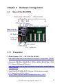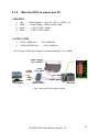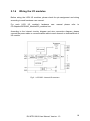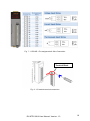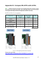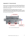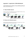
1
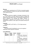
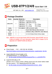
RU-87P1/2/4/8 User Manual Version 1.4 June 2014 Original Writer: Martin Hsu Last Writer: Anna Huang New Feature: A400 firmware adds Addr. Mode function that can help users update system from I-87Kn to RU-87Pn without modification software. About more detail information, please refer Chapter 2.3 Addr. Mode function ICP DAS, Co., LTD www.icpdas.com RU-87P1/2/4/8 User Manual, Version: 1.4 1 Table of Contents Chapter 1 1.1 Chapter 2 2.1 2.1.1 2.1.2 2.1.3 2.1.4 2.1.5 2.1.6 2.1.7 2.2 2.2.1 2.3 Chapter 3 3.1 3.1.1 3.1.2 3.2 3.2.1 3.3 3.4 Chapter 4 4.1 4.2 4.2.1 4.2.2 4.2.3 4.3 4.3.1 4.3.2 4.4 4.4.1 4.4.2 Introduction .................................................................................................. 6 Specifications ................................................................................................11 Hardware Configuration ............................................................................ 12 View of the RU-87PN ................................................................................... 12 Preparation ...................................................................................................... 12 Wire the 87Pn to power and PC ....................................................................... 13 Factory default value of 87Pn’s CPU module: .................................................. 14 RU-87Pn series CPU Module Description ........................................................ 16 Plug in the I/O modules: ................................................................................... 17 Wiring the I/O modules ..................................................................................... 18 Installing RU-87Pn extension unit..................................................................... 20 Setup the 87Pn system parameter............................................................... 21 Communication parameters of 87Pn CPU module: .......................................... 21 Addr. Mode function ..................................................................................... 24 Software Configuration ............................................................................. 29 Setup RU-87Pn with DCON Utility ............................................................... 29 87Pn Auto Config. Enable: ............................................................................... 32 87Pn Auto Config. Disable: .............................................................................. 36 Save & Load 87Pn Configure file ................................................................. 38 Save the module command to file: ................................................................... 39 Load & Write configure file ........................................................................... 42 Operating in off-line mode:........................................................................... 44 Software Development Kits (SDK) ............................................................ 49 PACSDK ...................................................................................................... 50 DCON LabVIEW .......................................................................................... 51 Procedure for using DCON_LabVIEW .............................................................. 51 LabVIEW Example (Reading multi-channel analog Input value) ....................... 53 LabVIEW Demo Program (Reading multi-channel analog input value) ............. 55 DCON InduSoft ............................................................................................ 56 Procedure for using the InduSoft bundled driver............................................... 56 InduSoft Example (Reading an analog input value) .......................................... 57 NAP OPC Server ......................................................................................... 60 Procedure for using the OPC Server ................................................................ 60 OPC Server Example (Reading an analog input value) .................................... 61 Appendix A : Dimension ................................................................................................. 63 A.1 – RU-87P1 ........................................................................................................... 63 A.2 – RU-87P2 ........................................................................................................... 64 A.3 – RU-87P4 ........................................................................................................... 65 A.4 – RU-87P8 ........................................................................................................... 66 Appendix B : Compare RU-87Pn with I-87Kn ................................................................ 67 Appendix C : Solution for 87K I/O module on the slot ................................................. 68 Appendix D : Description For ini Files .......................................................................... 73 Appendix E : Frame Ground ........................................................................................... 74 RU-87P1/2/4/8 User Manual, Version: 1.4 2 Appendix F : Application of RS-485 Network ................................................................ 75 F.1: Basic RS-485 network ......................................................................................... 75 F.2: Daisy chain RS-485 network ............................................................................... 75 F.3: Star type RS-485 network ................................................................................... 76 F.4: Random RS-485 network .................................................................................... 77 24.517062N,121.009899E RU-87P1/2/4/8 User Manual, Version: 1.4 3 FIGURE Fig.1:View of 87Pn................................................................................................. 12 Fig.2:Wire the 87Pn to power and PC ................................................................... 13 Fig.3:87Pn’s CPU module ..................................................................................... 14 Fig.4:About CPU module ....................................................................................... 15 Fig.5:RU-87P4/P8 CPU module description .......................................................... 16 Fig.6:Plug in the I/O structure ................................................. 錯誤! 尚未定義書籤。 Fig.7:I-87019R - Internal I/O structure ................................................................... 18 Fig. 8:I-87019R - Pin assignments & Wire Connection .......................................... 19 Fig. 9:I/O module terminal connection ................................................................... 19 Fig.10:Installing RU-87Pn extension unit ............................................................... 20 Fig.11:Setup the address of Rotary Switch on 87P4 CPU module ........................ 21 Fig.12:Function description of DIP switch on 87P4 CPU module .......................... 22 Fig.13:Run DCON Utility and Module Configuration ............... 錯誤! 尚未定義書籤。 Fig.14:When Auto Config. Enable, incorrect module can’t external communication ..................................................................................................................... 32 Fig.15:Click “Write to 87Pn” to complete 87Pn module configuration .................... 33 Fig.16:The status after complete the 87Pn module configuration .......................... 33 Fig.17:After configuring, you can find out the entire module .................................. 34 Fig.18:How to complete Auto-Configuration for 87Pn. ........................................... 35 Fig.19:When 87Pn Auto Config.: Disable, all the module can external communication ..................................................................................................................... 36 Fig. 20:Click ”Configure” to enter the configure screen.......................................... 39 Fig. 21:Select and setup the measurement range of module ................................ 40 Fig. 22:Write the settings to RU-87Pn and click “save configuration” .................... 40 Fig. 23:Save the configuration file.......................................................................... 41 Fig. 24:Load the settings and check the content of configuration file錯誤! 尚未定義 書籤。 Fig. 25:Confirmed the settings, then write to 87Pn CPU module錯 誤 ! 尚 未 定 義 書 籤。 Fig. 26:Load configuration and write to 87Pn CPU module ................................... 43 Fig. 27:Configure and save file in off-line mode ..................................................... 44 Fig. 28:Load Configuration and write to 87Pn CPU module in other computer ...... 44 Fig. 29:Off-line operation ....................................................................................... 45 Fig. 30:Off-line operation – Configure & Save file .................................................. 46 Fig. 31:Load configure file in another PC............................................................... 47 Fig. 32:Write the settings to RU-87Pn ................................................................... 48 RU-87P1/2/4/8 User Manual, Version: 1.4 4 Fig. 33:I-87K high/low profile series I/O modules .................................................. 67 Fig. 34:The search result between 87Pn and modules .......................................... 68 Fig. 35:DCON Utility shows the status of 87Pn expansion slot .............................. 68 Fig. 36:Frame Ground & Earth Ground .................................................................. 74 RU-87P1/2/4/8 User Manual, Version: 1.4 5 Chapter 1 Introduction RU-87Pn series is a remote intelligent I/O expansion unit that used to expand I-87K series I/O modules over the RS-485 for industrial monitoring and controlling applications. There are more than 50 I/O modules supported with the unit, including analog input/output, digital input/output, and counter/frequency I/O modules. RU-87Pn is designed to be used in harsh and noisy environment, so the hardware is manufactured with wide power input range (10 ~ 30 VDC) and operating temperature (-25 °C ~ +75 °C). It simplifies installation and maintenance of I/O modules with hot swappable and auto configuration, fault and error detection, dual watchdog, programmable power on and Safe Values. Various software development kits (SDK) and demos are provided, such as PACSDK, LabVIEW driver, InduSoft driver, Linux driver, OPC Server, etc. The I-87K series I/O modules plugged in the RU-87Pn can be easily integrated into variant software system. I-7561 USB to RS-232/422/485 RS-485 Converter RU-87P1/2/4/8 User Manual, Version: 1.3 6 Features Hot Swap The RU-87Pn doesn’t need to shut down its power to replace or plug I-87K I/O modules. Therefore, the whole system can keep operating without any interruption. Auto-Configuration Configurations of I-87K I/O modules can be pre configured and stored in the nonvolatile memory of the RU-87Pn. When the RU-87Pn is power on or an I-87K I/O module is plug in, the RU-87Pn automatically check and restore these configurations to each I-87K I/O modules on it. Easy Duplicate System Using the DCON Utility, you can easily make a backup of the I-87K module configurations and write to another RU-87Pn. This design can easily and quickly duplicate many RU-87Pn. Easy Maintenance and Diagnostic The basic configurations (includes station number, baud rate) are set by the rotary and DIP switch. The operator can use only one screwdriver to set the RU-87Pn. And there are several LED status indicators to show whether I-87K modules are configured and work properly. If one I-87K module is damaged, the operator just need to get one good I-87K module with the same item number to replace the damaged one. And then check the LED indicators to know whether the replacement is performed correctly. The switch and LED design makes it easy for maintenance. There is no PC and Notebook needed. Communication RS-485 industrial multi-drop network The RU-87Pn uses the industrial EIA RS-485 communication to transmit and receive data over long distance (1.2 Km). DCON protocol I-87K series I/O modules plugged in a RU-87Pn provide a simple command/response protocol (Called DCON protocol) for communication. All command/response are in easy used ASCII format. RU-87P1/2/4/8 User Manual, Version: 1.3 7 Fully Software Support The free charge software utility and development kits include DCON Utility: for configuration 1 2 EZ Data Logger EZ Data Logger is small data logger software. It can be applied to small Remote I/O system. With its user-friendly interface, users can quickly and easily build a data logger software without any programming skill. OPC Servers: OPC is an industrial standard interface based on OLE technology. With the OPC Server, I/O modules can be easily integrated to any software that has OPC client capability. Support Variant Software Develop Toolkits It’s free charge for PACSDK, LabVIEW driver, InduSoft driver, Linux driver, and etc driver. RU-87P1/2/4/8 User Manual, Version: 1.3 8 Rugged Industrial Environment Dual watchdog design The I-87K series I/O modules provides module watchdog and host watchdog. The module watchdog is a hardware watchdog; the host watchdog is a software watchdog. The module watchdog is designed to automatically reset the microprocessor when the module hangs. The host watchdog monitors the host controller (PC or PLC). The output of module can go to the Safe Value state when the host fails. Programmable power on and Safe Value The analog and digital output of modules can be programmed power on and Safe Value. Wide range power input (10~30 VDC) Wide range operating temperature (-25 °C ~ +75 °C) RU-87P1/2/4/8 User Manual, Version: 1.3 9 Update I-87Kn to RU-87Pn without modification software. User can update I-87Kn to RU-87Pn without modification his software, then it can have How Swap, Auto-Configuration and etc useful features as above description. Note: In RU-87P1/2/4/8 firmware A4.00 or later version, user can set Addr. Mode “ON” and address of I/O module begin as 1. Then user can update I-87Kn to RU-87Pn using the same software program to controller I-87K module. About more detail information about Addr. Mode, please refer Chapter 2.3 Addr. Mode function RU-87P1/2/4/8 User Manual, Version: 1.3 10 1.1 Specifications Interface Type (RS-485) Baud rate 115200 bps maximum Distance 1.2 Km (4000 ft) maximum Isolation 3000 VDC ESD Protection +/- 4K Contact Discharge and +/- 8K Air Discharge Switch Rotary Switch x2 , For RS-485 address DIP switch 8 bit *1, For auto configuration, check sum, baud rate LED Indicators Power Yes System Ready Yes Auto-Configuration Yes Slot Status Yes I/O Expansion Slots Hot Swap Yes Auto-Configuration Yes Support Module Type High profile I-87K module only Dimensions (W x H x D) RU-87P1 64 x 117 x 110 mm RU-87P2 95 x 132 x 111 mm RU-87P4 188 x 132 x 111 mm RU-87P8 312 x 132 x 111 mm Power Input Range 10~30 VDC Reverse Polarity Protection Yes Isolation 3000 VDC Frame Ground Yes Module Consumption Power Board Driving RU-87P1 1W 5W RU-87P2 1W 8W RU-87P4 2W 15 W RU-87P8 2.4 W 30 W Environment Operating Temperature –25 °C ~ +75 °C Storage Temperature –30 °C ~ +85 °C Humidity 5 ~ 95% RH, non-condensing RU-87P1/2/4/8 User Manual, Version: 1.3 11 Chapter 2 2.1 Hardware Configuration View of the RU-87PN Fig.1:View of 87Pn 2.1.1 Preparation Power Supply: +10 V ~ +30 V / DC (Ex: DP-665) http://www.icpdas.com/products/Accessories/power_supply/power_list.htm Converter: RS-232 to RS-485 (Ex: I-7520) or USB to RS-485 (Ex: I-7561) CD: \ Napdos\7000\Manual\7520.pdf or http://www.icpdas.com/products/Industrial/communication_module/commun ication_list.htm Install the DCON Utility to PC (Version 4.5.0 or above version) CD: \ Napdos\Driver\DCON_Utility or ftp://ftp.icpdas.com/pub/cd/8000cd/napdos/driver/dcon_utility/ RU-87P1/2/4/8 User Manual, Version: 1.3 12 2.1.2 Wire the 87Pn to power and PC RU-87P4 1. 2. 3. 4. +Vs ←→ Power Supply : +Vs (+10 ~ 30 V) / I-7520 : +Vs GND ←→ Power Supply : GND / I-7520 : GND Data+ ←→ I-7561/ I-7520 : Data+ Data- ←→ I-7561/ I-7520 : Data- I-7561/ I-7520 1. I-7561’s USB Port ←→ PC’s USB Port 2. I-7520’s RS-232 Port ←→ PC’s COM Port P.S. If using I-7520, don’t forget to connect the power (+Vs, GND)! Power Supply +10~+30 VDC I-7520: RS-232 or I-7561: USB PC (COM X) I-7520: (+Vs, GND) (+Vs, GND) (+Vs, GND) I-7520/7561 (Data+, Data-) (Data+, Data-) RU-87P4 Fig.2:Wire the 87Pn to power and PC RU-87P1/2/4/8 User Manual, Version: 1.3 13 2.1.3 Factory default value of 87Pn’s CPU module: The factory default values are as following table: Switch Rotary Switch (Address) DIP switch (SW1) Label Setting Description H 0 Net address = 1 L 1 Auto Config. ON Enable Checksum OFF Disable Baud Rate ON, ON, ON 115200 Addr. Mode OFF CPU address as Rotary Switch (Note 1.) H: High Byte L: Low Byte Note1: The Addr. Mode is support by RU-87P1/2/4/8 firmware A400 or later version. When Addr. Mode is “OFF”, the address between CPU and I/O module are the same as old firmware version. Note2: The ON of DIP switch for 87P1 & 87P2 are switching to the left, for 87P4 & P8 are to the right. RU-87P1 / RU-87P2 RU-87P4 / RU-87P8 0: 0: ON: ON: Fig.3:87Pn’s CPU module RU-87P1/2/4/8 User Manual, Version: 1.3 14 System LED Rotary Switch (Address) 1~255 (0x01) 1. 2. Dip Switch (SW1) Auto Config (On) Checksum (Off) Baud Rate (On,On,On,115200) Addr. Mode (Disable) Module Status LED: 1. Configuring Flashing per 100ms. 2. Pass Turn off. 3. Fail Flashing per 2second. (Red) PWR LED: Power On – Bright. Power Off – Dark. (Green) S.RDY LED Any module configuring Flashing per 100ms 2. All of the modules pass the test Bright. 3. One or more module test fail Flashing per 2 second. 1. (Green) Auto Config. LED: 1. Auto Config. On – Bright. 2. Auto Config. Off – Dark. Fig.4:About CPU module RU-87P1/2/4/8 User Manual, Version: 1.3 15 2.1.4 RU-87Pn series CPU Module Description Check the left side of the Power Board for the CPU module LED and DIP switch description. Fig.5:RU-87P1/P2 CPU module description RU-87P1/2/4/8 User Manual, Version: 1.3 16 2.1.5 Plug in the I/O modules: At present, ICP DAS divides most of the same I-87K I/O module into the Low Profile and High Profile two kinds of version, if you want to use the module on 87Pn expansion slot, you must choose the High Profile to assure Auto Config. and Hot Swap function is normal operation. The related product information about I-87K I/O module is in the CD. You can refer I-87K High Profile series I/O modules in following path: CD:\Napdos\DCON\IO_Module\87k_modules.htm or to following web-site http://www.icpdas.com/root/product/solutions/remote_io/rs-485/i-8k_i-87k/i-8k_ i-87k_selection.html RU-87Pn is only support I-87K series High profile modules. Example: Plug in I-87019R to Slot 0 After plugged in, the slot indicator is flashing per 100 ms. When configuration is completed, the LED becomes off. If configuration is failed, the LED is always on. RU-87P1/2/4/8 User Manual, Version: 1.3 17 2.1.6 Wiring the I/O modules Before wiring the I-87K I/O modules, please check the pin assignment and wiring according to each hardware user manual. For each I-87K I/O module's hardware user CD:\Napdos\DCON\IO_Module\87k_modules.htm manual please refer to According to the internal circuitry diagram and wire connection diagram, please connect the power cable or communication cable to each channel on terminal block of I/O module. Fig.6:I-87019R - Internal I/O structure RU-87P1/2/4/8 User Manual, Version: 1.3 18 Fig. 7:I-87019R - Pin assignments & Wire Connection Terminal Block Fig. 8:I/O module terminal connection RU-87P1/2/4/8 User Manual, Version: 1.3 19 2.1.7 Installing RU-87Pn extension unit Method 1: using the screw to fixed. Method 2: using the DIN rail clips to fixed. Frame Ground DIN-Rail Clips Fig.9:Installing RU-87Pn extension unit RU-87P1/2/4/8 User Manual, Version: 1.3 20 2.2 2.2.1 Setup the 87Pn system parameter Communication parameters of 87Pn CPU module: The 87Pns setup its Address, Baud rate and Checksum by adjusting the DIP switch and Rotary Switch which on 87Pn CPU module. It’s not setup by software, please setup the communication condition at first and don't change the communication condition under operating mode. Step1. Adjusting the Rotary Switch as following diagram, Address is set to the hexadecimal code, divided into High byte and low byte two groups. Ex: The high byte turns to 0, the low byte turns to 1 then the address of RS-485 is 16x0+1=1; Ex: The high byte turns to 1, the low byte turns to 0 then the address of RS-485 is 16x1+0=16. Fig.10:Setup the address of Rotary Switch on 87P4 CPU module Note1: The maximum address for RU-87P1/2/4/8 and I/O modules only can be set as 127(0x7F) Note2: If you change the address to 00, no matter where is the actual position of DIP switch, the system parameter will return to default value! (Auto config. On, Checksum off, Baud rate 115200) RU-87P1/2/4/8 User Manual, Version: 1.3 21 Step2. Setup the DIP switch as following description: Fig.11:Function description of DIP switch on RU-87P4 CPU module Note 1: When parameter is changed, RU-87Pn will auto re-change the internal communication parameters or system parameters, if the external control project is running in the same time, it will cause communication error. Thus don’t change communication parameters and system parameter when system is running. Note 2: if 87Pn’s communication parameter has been changed, the external control program must to change the related parameters synchronously. Note 3: Addr. Mode function is only support by RU-87P1/2/4/8 firmware A400 or later version. RU-87P1/2/4/8 User Manual, Version: 1.3 22 Step3. Communication parameters of I-87K I/O modules: The communication parameters of 87K I/O modules are Auto-configured by CPU module. Rule 1: the Baud Rate & Checksum of the I/O modules on 87Pn expansion slot are always the same as 87Pn CPU module. (Default: Auto Config.: Enable , Baud Rate: 115200 , Checksum: Disable) Rule 2: the Net Address of CPU and I/O modules on the slot is based on Rotary Switch and Addr. Mode. RU-87P1/2/4/8 User Manual, Version: 1.3 23 2.3 Addr. Mode function In RU-87P1/2/4/8 firmware A4.00 or later version, user can set Addr. Mode “ON”. and address of 1st I/O module cab be set as 1. User can update system from I-87Kn to RU-87Pn without modification software program to controller I-87K modules. The address of Addr. Mode “OFF” is the same as old firmware version. The relationship of address for CPU and I/O module will be as below: Addr. Mode ON OFF CPU address Rotary Switch address +128 Rotary Switch address I/O modules address Address of Slot 0 will be as Rotary Switch Address of Slot 0 will be as Rotary Switch address+1 For example: There is a RU-87P4 and rotary switch address as 1, the result for CPU and I/O modules address as below: RU-87P1/2/4/8 User Manual, Version: 1.3 24 Addr. Mode OFF, Rotary Switch address 1: The address of CPU will as Rotary Switch (CPU address 1) and the address of Slot will as Rotary Switch +1, +2 and etc (I/O address 2,3,4,5). This function is the same as old firmware version (without Addr. Mode function). Addr. Mode ON, Rotary Switch address 1: The address of CPU will as Rotary Switch+128 (CPU address=1+128=129,0x81), the address of Slot will as Rotary Switch, +1 and etc (I/O address= 1,2,3,4). This function is support RU-87P1/2/4/8 firmware A400 or later version. RU-87P1/2/4/8 User Manual, Version: 1.3 25 Addr. Mode ON can fix two issues: 1. The address of I/O modules can be start as address 1: In RU-87Pn old firmware, the minimum address of CPU must be 1 and I/O must be 2. If I/O address start as 1 in I-87Kn, it need to modify software when update I-87Kn to RU-87Pn. Now user can set Addr. Mode as ON on RU-87Pn A400 or later firmware, it can set I/O address as below: RU-87P1/2/4/8 User Manual, Version: 1.3 26 2. The address of I/O modules can be continuous: If address of I/O modules is continuous (for example address 1~ address 8), it needs to modify his software using old RU-87Pn firmware. (for example: I/O address for 2~5, and 7~10, address 1 and 6 for CPU module.) Now user can set Addr. Mode as ON, it can set address of I/O modules continuous as below: I/O modules is continuous, address 1 ~ address 7 RU-87P1/2/4/8 User Manual, Version: 1.3 27 If user uses 2 or more RU-87Pn and there is no module on some of slot, the Net Address of I/O modules will be reserved. User needs to set his system as above picture and can’t set its system as below or it will be caused some problems. Slot 3 of 1st RU-87Pn (address 4) without no module, and it needs to be reserved. The 2nd RU-87Pn can’t use that address (2nd RU87P4 slot 0 address 4) or it will caused some problem. RU-87P1/2/4/8 User Manual, Version: 1.3 28 Chapter 3 Software Configuration In this chapter, we will use DCON Utility to complete software configuration of the RU-87Pn, please confirm the hardware equipment has connected and communication parameters of 87Pn CPU module has setup completes. (Please refer to Chapter 2) 3.1 Setup RU-87Pn with DCON Utility 3.2 Save & Load 87Pn configure file 3.3 Load & Write configure file 3.4 Operating in off-line mode 3.1 Setup RU-87Pn with DCON Utility At first, please run DCON Utility then click “COM Port” to select COM Port, baud rate and etc communication parameters. 2 1 RU-87P1/2/4/8 User Manual, Version: 1.3 29 Please click “search” button to start searching module. 3 At the first time you can search for “RU-87Pn” only, because the slots of RU-87Pn haven’t completed the configuration. The “[X,X,X,X]” of “Status” means the configuration of that slot is not completed or corrected. Please click “stop search” to stop the search. 4 Fig 12 When found RU-87P1 out. Click to stop search. [x] of “Status” means the configuration of that slot I/O module is not completed or corrected. Users can click “RU-87P1” module name to configure slot I/O module. RU-87P1/2/4/8 User Manual, Version: 1.3 30 Click “RU-87P11” to setup I/O slots. 5 RU-87P1/2/4/8 User Manual, Version: 1.3 31 3.1.1 87Pn Auto Config. Enable: In Fig.12 "Auto Config. ON" expressed that the 87Pn's Auto-Configuration function is "enable", "off" means "disable". Working Distinction: If I-87K I/O modules didn’t pass the 87Pn correct setup, and install into expansion slot under “Auto Config. Enable” mode, it will regard as incorrect module. For guarantee system's normal operation, the 87Pn will forbid this module external communication. You can’t search and configure I/O modules directly by DCON Utility. The “Auto Config. Enable [X,X,O,X,X,O,X,X]“ in Status column means the module configurations of that slot are some correct (O is means configuration correct) and some is not correct (X is means configuration not correct). Click “RU-87P8” and select to enter configure screen and know the detail settings about module. Fig.12:When Auto Config. Enable, incorrect module can’t external communication In 87Pn configure screen, you can see the scanned module name in ”Scanned I/O on Slot“ column. Click "Set As Scanned” button to assign module name and click "configure" to setup the I/O module according to the user demand. Finally click "write to 87Pn" for the settings to take effect. RU-87P1/2/4/8 User Manual, Version: 1.3 32 1 2 3 Fig.13:Click “Write to 87Pn” to complete 87Pn module configuration Fig.14:The status after complete the 87Pn module configuration RU-87P1/2/4/8 User Manual, Version: 1.3 33 As above, the I-87K I/O modules on 87Pn expansion slot has configured correctly by "DCON Utility", and then search the module again, you can see the module appear in the search screen. The ”Auto Config. Enable [0,0,0,0]” of “Status”, means “The I/O configuration of each slot is correct. Each plugged I/O module will be listed under the RU-87Pn. Fig.15:After configuring, you can find out the entire module If the module passed correct configuration, some day when module damage, you don’t need to shutdown the power, just remove the damaged module and install the same model number of new module. You needn't configure it again, 87Pn will write the previous settings to the module automatically. RU-87P1/2/4/8 User Manual, Version: 1.3 34 Remove the damaged module Plug in a new one with the same model number. Fig.16:How to complete Auto-Configuration for 87Pn. RU-87P1/2/4/8 User Manual, Version: 1.3 35 3.1.2 87Pn Auto Config. Disable: Working Distinction: In 87Pn Auto Config. Disable mode, allow the I-87K I/O modules of expansion slot to external communications. Therefore, when you perform searching by DCON Utility, you could find 87Pn CPU module as well as 87K I/O modules on the expansion slot. Fig.17:When 87Pn Auto Config.: Disable, all the module can external communication In 87Pn “Auto Config. Disable”, indicate your hardware device is under “disable” mode. You can’t make any configuration under this mode. the communication parameters of I-87K I/O module which on expansion slot can’t configured by user, it must Auto-Configure by 87Pn, the other usage is the same as the module insert into I-87K4/5/8/9 expansion unit. In 87Pn “Auto- Config. Disable” mode, doesn't support Auto-Configuration. When module damage, and replace another same model number the module directly, because of their settings (e.g. Type code) may be different, thus can’t ensure its normal working. The user must use DCON Utility to re-configure based on the setting value, and replies the normal operation. Note:In DCON Utility search screen, the message in status column of 87Pn RU-87P1/2/4/8 User Manual, Version: 1.3 36 The meaning of “ Auto Config. Enable [0,X,0,0] “ as following description:: 0:Means the module configuration on this slot is successful or have no module. X:Means the module configuration on this slot is uncorrected. If the status column of 87Pn shows “Auto Config. Enable [0,0,0,0]”, means the “Auto Config.” of DIP switch is switching to the “On”, and the I/O configuration of each slot is correct or has no module. If the status column of 87Pn shows “Auto Config. Disable [0,0,0,0], means the “Auto Config.” of DIP switch is switching to the “Off”, and the I/O configuration of each slot can initialization success or have no module. RU-87P1/2/4/8 User Manual, Version: 1.3 37 3.2 Save & Load 87Pn Configure file When using 87Pn operation screen of DCON Utility to configure the I-87K I/O module, DCON Utility will automatically save the necessary information under the installing path “config\”, the file recording some information of related module that will be saved in 87pn, when save as new file, it can be use for system recover and system backup. The related format and detail about configure file, please refer to Appendix D. Here, just description how to save the file as oneself needs and how to load from files. Note1: When user open the operation interface of 87Pn, if there is the same file in default path will be deleted. Note2: Using ”Configure” and ”Write To 87Pn” functions in 87Pn operation screen of DCON Utility will automatically save the related data of module of each slot as filename of fixed format and the same path, if user want to use the file as system recover, system backup or remote support, the best way is save the default file as another name to avoid the file been deleted when next time you open the operation interface of 87Pn. RU-87P1/2/4/8 User Manual, Version: 1.3 38 3.2.1 Save the module command to file: When all modules has configured properly according to the requirement, because each time entered the configuration screen will delete the default file and re-build, so suggestion to save the settings as another files, if the settings is carelessly changed or need to duplicate the same content of configure, can load in the configure file and write in 87Pn CPU module through operation screen of DCON Utility. The operation steps is very easy, using ”Configure” to setup each I/O module and write the settings to 87Pn, then click ”Save Configuration” button and input the description or notes for this configuration file. Finally, input the file name of this project to complete. Please refer to the description as following diagram. Fig. 18:Click ”Configure” to enter the configure screen RU-87P1/2/4/8 User Manual, Version: 1.3 39 Fig. 19:Select and setup the data format of module 1 2 Fig. 20:Write the settings to RU-87Pn and click “save configuration” RU-87P1/2/4/8 User Manual, Version: 1.3 40 Fig. 21:Save the configuration file You can save this file as a backup files. If RU-87Pn is damaged, you can write it to a new RU-87Pn without configure I/O module again. You also can write it for the others the same system RU-87P1/2/4/8 User Manual, Version: 1.3 41 3.3 Load & Write configure file If you sure the contents of configure files is what you need, you can load the configuration and write to 87Pn at the same time. As following diagrams, this function is useful for a lot of copy to other 87Pn (as Fig.26). 1 2 RU-87P1/2/4/8 User Manual, Version: 1.3 42 3 Fig. 22:Load configuration and write to 87Pn CPU module You can copy file to the others the same system and write configuration to all modules without configure it one by one. RU-87P1/2/4/8 User Manual, Version: 1.3 43 3.4 Operating in off-line mode: The operation in off-line mode means the computer which operate DCON Utility without connect any module of 87Pn, Using DCON Utility to generated and edit the module command for 87Pn requirement, and then write the command file to another computer which connected with 87Pn , this usage is convenient for remote support or system backup. The contents as following Fig.27、Fig.28. To Configure 87Pn Offline To Generate Configured file Fig. 23:Configure and save file in off-line mode On the other side, DCON Utility loads the configured file and writes to 87Pn directly. Fig. 24:Load Configuration and write to 87Pn CPU module in other computer RU-87P1/2/4/8 User Manual, Version: 1.3 44 Step1 : Select the Module ID, Address, Baudrate and Checksum. Fig. 25:Off-line operation RU-87P1/2/4/8 User Manual, Version: 1.3 45 Step2 : Select and configure the I/O module, then save the settings as another file name, or else next time when you open the 87Pn screen, the previous settings will be deleted. 2 1 3 Fig. 26:Off-line operation – Configure & Save file 4 Note: The configure file will be save to C:\ICPDAS\DCON_Utility\for_users RU-87P1/2/4/8 User Manual, Version: 1.3 46 Step3 : Run DCON Utility in another computer which has connected with 87Pn, load the settings into DCON Utility and you can press "Configure" button to check the settings has written to 87Pn correctly. Follow the steps, you can complete the function of Auto-Configuration also can write to 87Pn directly after loading configuration. As following diagram: 1 Fig. 27:Load configure file in another PC 2 Click “Configure” to check the settings. RU-87P1/2/4/8 User Manual, Version: 1.3 47 3 Fig. 28:Write the settings to RU-87Pn RU-87P1/2/4/8 User Manual, Version: 1.3 48 Chapter 4 Software Development Kits (SDK) The ICP DAS provides a series of free software development kits, enables the customer to be fast and simply completes the system setup. Related software tools are in the CD, please refer to following diagram: CD: \ Napdos Driver DCON_Utility Pro DCON_Utility PACSDK DCON_LabVIEW DCON_InduSoft DCON_DasyLab EZ_Data_Logger DCON_Linux NapOPCSvr RU-87P1/2/4/8 User Manual, Version: 1.3 49 4.1 PACSDK PACSDK provide program developers to read the program interface which used on control I/O modules, the position of CD place provides a few basic and simple examples, user can understand how to read the control I/O module through the DLL in following examples: Supported Windows OS for PC Operation System Windows XP Windows 7 Windows All document for APCSDK is located at CD or FTP (latest version): CD: \ Napdos\Driver\PACSDK or ftp://ftp.icpdas.com/pub/cd/8000cd/napdos/driver/pacsdk/ PACSDK can be used on C,C++,C#,Delphi,Borland C and etc Development environment. About more description about it ,please refer its user manual : ftp://ftp.icpdas.com/pub/cd/8000cd/napdos/driver/pacsdk/document/ Step5: Write the program code RU-87P1/2/4/8 User Manual, Version: 1.3 50 4.2 DCON LabVIEW DCON LabVIEW Bundled driver for LabVIEW Supported module: I-7000/8000/87K Series (With DCON Protocol) Supported OS: Windows 98/NT/2K/XP File Location: CD: \Napdos\Driver\DCON_Labview 4.2.1 Procedure for using DCON_LabVIEW Step 1 : Install the DCON LabVIEW by executing: CD:\Napdos\Driver\ DCON_Labview\ DCON_Labview.exe After installation, the related information can be found as below: RU-87P1/2/4/8 User Manual, Version: 1.3 51 8000 Demo: Demo programs for I-8000 I/O modules. 8000.llb: LabVIEW library contains all sub-vi for I-8000 I/O modules CallDLLinLabVIEW.pdf: Explains how to call a sub-vi of in LabVIEW. DCON_DLL.pdf: Descriptions of all sub-function in DCON_DLL. Step 2: Create a new LabVIEW program. Refer the DCON_DLL.pdf about detail description of the sub-vi and where to select the sub-vi in various library of DCON_LabVIEW. Step 3: Select the sub-vi form Functions Palette >> Select a VI… RU-87P1/2/4/8 User Manual, Version: 1.3 52 4.2.2 LabVIEW Example (Reading multi-channel analog Input value) Step 1 : Select the target *.lib file (LabVIEW library file) Step 2 : Select the desired sub-vi RU-87P1/2/4/8 User Manual, Version: 1.3 53 Step3 : Put the icon of selected sub-vi on Block Diagram, refer the “Help” >> “Show Help” or “DCON_DLL.pdf” in step1 for detail. Step 4 : Draw the data flow of sub-vi. RU-87P1/2/4/8 User Manual, Version: 1.3 54 4.2.3 LabVIEW Demo Program (Reading multi-channel analog input value) Step 1: Select the appropriate demo program (ex. AnalogInAll.vi) by the name according with module’s function (ex. I-8017 / AI ). Step2: Set the parameters 1 2 You could also refer the “Help”>>”Show Context Help” for getting the simple description of those parameters. Step3 : Run the Demo. RU-87P1/2/4/8 User Manual, Version: 1.3 55 4.3 DCON InduSoft DCON InduSoft Bundled driver for InduSoft Supported module: I-7000/8000/87K Series (With DCON Protocol) Supported OS: Windows 98/NT/2K/XP/CE File Location: CD: \Napdos\Driver\DCON_InduSoft 4.3.1 Procedure for using the InduSoft bundled driver Step 1: Read the basic and important documents Readme.txt: contains the basic and important information, including: Files on the shipped CD Reversion.txt: contains the reversion information, including Bugs fixed New modules supported Step 2: Install the InduSoft bundled driver by executing CD:\Napdos\Driver\DCON_InduSoft\Setup\setup.exe Step 3: Read the manuals describing how to start The DCON.pdf user’s manual describes how to use the InduSoft bundled driver Step 4: Run the demo programs (ICPDriverTest.zip) to test I/O modules and learn the functions RU-87P1/2/4/8 User Manual, Version: 1.3 56 4.3.2 InduSoft Example (Reading an analog input value) The following is an example of reading analog values from an I-87018 inserted in slot 0 of an 8410/8810. Step 1: Run the DCON Utility to configure the I/O modules Step 2: Run InduSoft and create a new project Step 3: Include the DCON driver 1 2 3 4 Step 4: Configure the DCON driver 2 3 1 1 1 RU-87P1/2/4/8 User Manual, Version: 1.3 57 Step 5 : Insert tags to connect to I/O modules The address format is [Address : Module ID : Slot : Channel] 1 1 2 1 Step 6 : Arrange all the components on the form RU-87P1/2/4/8 User Manual, Version: 1.3 58 Step 7: Double click the text box to assign a tag to it. 1 1 2 Step 8 : Run the project RU-87P1/2/4/8 User Manual, Version: 1.3 59 4.4 NAP OPC Server NAP OPC Server OPC Server Supported Module: I-7000/8000/87K Series (With DCON Protocol) Modbus embedded controller ISaGRAF embedded controller Supported OS: Windows 98/NT/2K/XP/CE File Location:: CD:\Napdos\NapOPCSvr OPC (OLE for Process Control) is the first standard resulting from the collaboration of a number of leading worldwide automation suppliers working in cooperation with Microsoft. Originally based on Microsoft's OLE COM (component object model) and DCOM (distributed component object model) technologies, the specification defined a standard set of objects, interfaces and methods for use in process control and manufacturing automation applications to facilitate interoperability. The COM/DCOM technologies provided the framework for software products to be developed. There are now hundreds of OPC Data. 4.4.1 Procedure for using the OPC Server Step 1: Read the basic and important documents Readme.txt: contains the basic and important information, including Files on the shipped CD Reversion.txt: contains the reversion information, including Bugs fixed New modules supported Step 2: Install the OPC Server by executing CD:\Napdos\NapOPCSvr\NapOPCServer.exe Note: If there is an older version of Nap OPC Server installed on the PC, It must be uninstalled before installing the new version. Step 3: Read the manuals describing how to start The NapOPCSvr.pdf is the user’s manual describing how to use the OPC Server RU-87P1/2/4/8 User Manual, Version: 1.3 60 4.4.2 OPC Server Example (Reading an analog input value) The following is an example of reading analog values from an I-87018 inserted in slot 0 of an 8410/8810. Step 1: Run the DCON Utility to configure the I/O modules Step 2: Run the OPC Server to search for I/O modules on COM1 1 2 3 RU-87P1/2/4/8 User Manual, Version: 1.3 61 Step 3: Save the configuration and close the OPC Server Step 4: Run SCADA software to connect to the OPC Server The OPC Server user’s manual lists the procedures for the following SCADA software: LabVIEW National WIZCON iFix InduSoft Citect Please refer to “Chapter 4 Connecting to the OPC Server” for more details. RU-87P1/2/4/8 User Manual, Version: 1.3 62 Appendix A : Dimension A.1 – RU-87P1 RU-87P1/2/4/8 User Manual, Version: 1.3 63 A.2 – RU-87P2 RU-87P1/2/4/8 User Manual, Version: 1.3 64 A.3 – RU-87P4 RU-87P1/2/4/8 User Manual, Version: 1.3 65 A.4 – RU-87P8 RU-87P1/2/4/8 User Manual, Version: 1.3 66 Appendix B : Compare RU-87Pn with I-87Kn Note: I-87K I/O module has divides into the high profile (new version) and the low profile (old version) two kinds, only I-87K high profile series I/O modules can support Hot Swap and Auto-Configuration function correctly. RU-87Pn & I-87Kn I/O unit comparison Supported RU-87Pn with Auto Config. Enable RU-87Pn with Auto Config. Disable I-87Kn I-87K Low Profile module I-87K High Profile module -- -- I-87K module Hot Swap -- Auto- Communication parameter Setup -- Auto-Configuration -- -- Fig. 29:I-87K high/low profile series I/O modules Please refer to web page : http://www.icpdas.com/products/PAC/I-8000/8000_IO_modules.htm RU-87P1/2/4/8 User Manual, Version: 1.3 67 Appendix C : Solution for 87K I/O module on the slot When insert the module on the expansion slot of 87Pn, the same time 87Pn CPU will detect the module name and respond the status of interacting between 87Pn and module. As following diagram, the search result only find out the RU-87P4 and a 87019R which on slot 0, the Status column shows Auto Config. Enable [O,O,X,O] Fig. 30:The search result between 87Pn and modules Click the name “RU-87P4” entering the operation screen to know the settings of 87Pn and the status detected by 87Pn CPU, the module status code in "Slot Configuration Slot" column means the different error message. You may click "Error Code Reference" to inquire the solution and the meaning of error code. Fig. 31:DCON Utility shows the status of 87Pn expansion slot As following table, you can accord the error code and LED lamp status to find out the problem solution. RU-87P1/2/4/8 User Manual, Version: 1.3 68 Table 1 : The Error Code in Auto Config. Enable mode Error Slot LED Code (Red) 00H 01H 02H Dark (ok) Flashing (Warning) Status Description Solution OK OK None Module scanned in Empty Slot 1. There is a module scanned in 1. Remove the module this empty setting slot. Reconfigure it with DCON Utility. 2. The first time to setup, no 1. Click "Set As Scanned" button and configure initial value. module again 2. Click "Write To 87Pn" button to write settings to 87Pn. 1. Check the I-87K I/O module's firmware. Configure failure: This is a 87K I/O module firmware compatibility problem Flashing Commands not . Some commands at this slot (Warning) comparable might be too new for this old firmware of 87K I/O module, but it is not serious for system operation. 03H Bright (Error) Configuration Failed 04H Bright wrong Configure failure: Some commands are not supported by this 87K I/O module and this error will be serious for system operation. Configure failure: * Run DCON UtilityTerminalDCON command Line setup Baud RateCommand: $AAF (EX. 01F) Send * You can see the version, Respond=!01A1.9 2. Update the 87K I/O module with a new firmware version. 1. Check the 87K I/O module firmware 2. Update the 87K I/O module with a new firmware version. 1. Run DCON Utility. RU-87P1/2/4/8 User Manual, Version: 1.3 69 (Error) 05H 06H Bright (Error) Bright (Error) Configuration format Read Configuration failed Can not find module The format of configured commands is wrong for DCON Protocol. The memory data is failed: The configured commands are wrong for DCON Protocol. The configured module at this slot has been removed. It is empty now. 2. Click the "Write To 87Pn" button to write the settings to 87Pn CPU again. 1. Run DCON Utility. 2. Click the "Write To 87Pn" button to write the settings to 87Pn CPU again. 1. Please insert a correct module as previous configured one. 2. Or configure with DCON Utility as "Empty" and click the "Write To 87Pn" button to write the configuration to 87Pn CPU. Configure failure: 07H Bright (Error) Incorrect module name The insert & configure module name are different, The module inserted in this slot insert the correct one or run the DCON Utility to is not the same as previous modify the settings accord with the module name. configured. Configure failure: 08H 09H Bright (Error) Bright (Error) Internal INIT* pin failed Module address over 255 (FFh) 1. Please restart the power to initialize to I/O module 2. If it still failed to initialize, send it back to factory to The INIT Pin is failed to connect check. with the GND and module failed Note: RU-87Pn only supports high profile 87K I/O to initialize. modules. The maximum address of 87P1 is 254 (FEh) The module address is over 255 87P2 is 253 (FDh) (FFh). 87P4 is 251 (FBh) 87P8 is 247 (F7h) RU-87P1/2/4/8 User Manual, Version: 1.3 70 0AH 0BH 0CH Bright (Error) This error might be caused by The command following reasons. count saved to 1. Command length error. Please configure this 87K I/O module with DCON 87Pn is not the 2. Command checksum error. Utility, and click the "Write To 87Pn" button to write same as DCON 3. Communication error during the configuration to 87Pn CPU again. Utility the process of writing commands to 87Pn. Bright (Error) Please restart the power to initialize to I/O module, or This error might be caused by configure this 87K I/O module with DCON Utility, and Module following reasons. Module click the "Write To 87Pn" response failed response failed above 5 times. This function only support at 87Pn firmware A300 or later version. Bright (Error) Module is not 87K high profile I/O modules. Note:87Pn only supports 87K high profile I/O modules, Module name This error might be caused by Please replace it as 87K I/O module invalid invalid module name format This function only support at 87Pn firmware A300 or later version. Table 2 : The Error Code in Auto Config. Disable mode Error Code Slot LED (Red) Status Description Solution 80H Dark (ok) Initialize ok setup success None RU-87P1/2/4/8 User Manual, Version: 1.3 71 81H 82H The INIT Pin is failed to connect with the GND and module failed to initialize. If it still fails after restart the 87Pn many times, please send the 87K I/O module back to factory to check. Bright (Error) Internal INIT* pin failed Bright (Error) The maximum address of 87P1 is 254 (FEh) Module address The module address is over 255 (FFh). 87P2 is 253 (FDh) over 255 (FFh) 87P4 is 251 (FBh) 87P8 is 247 (F7h) You can see the LED signals on 87Pn CPU module to know whether the 87Pn is operating properly. Please refer to appendix. Auto Config. LED (Green) S.RDY LED (Green) Slot Status LED (Red) Always ON Always OFF Always ON Flash Flash Always ON Always ON Always OFF Flash Always ON Auto Config. Enable No Error Warning Always ON Failed Auto Config. Disable No Error Failed Always OFF RU-87P1/2/4/8 User Manual, Version: 1.3 72 Appendix D : Description For ini Files While you save the configuration file, the DCON Utility will save as .ini file. The default path of file as below: C:\ICPDAS\DCON_Utility\for_users The INI file explains as follows: [SYSTEM] Section 1: Unit Name UNIT=87P1 [COMMENTS] Date Time=2007/6/1 下午 02:30:41 Description=This is a demo for 87P1 Section 2: Created date time and description for configuration file. [Slot0 Comments] ID=87017R MODULE_CONFIG= Net Address=> Baud Rate=> 2 115200 Type Code=> [0D] +/- 20 mA Format=> Engineering Format Section 3: Description for each slot module’s configuration. CHANNEL_ENABLE_STATUS= &h0F ********************************************* [Slot0] ID=87017R TOTAL=2 C00=25020D0A2021F C01=2450F21F Section 4: The Configuration Commands for each slot. RU-87P1/2/4/8 User Manual, Version: 1.3 73 Appendix E : Frame Ground Electronic circuits are constantly vulnerable to Electro-Static Discharge (ESD), which become worse in a continental climate area. Some I-7000, M-7000 and I-8000 series modules feature a new design for the frame ground, which provides a path for bypassing ESD, allowing enhanced static protection (ESD) capability and ensures that the module is more reliable. The following options will provide a better protection for the module: The RU-87Pn controller has a metallic board attached to the back of the plastic basket as shown in the Figure 36 below. When mounted to the DIN rail, connect the DIN rail to the earth ground because the DIN rail is in contact with the upper frame ground as shown in the Figure 36 below Frame Ground DIN-Rail Clips Connect to the Earth Ground Fig. 32:Frame Ground & Earth Ground RU-87P1/2/4/8 User Manual, Version: 1.3 74 Appendix F : Application of RS-485 Network The RS-485 length can be up to 4000 ft or 1.2 km over a single set of twisted –pair cables, if the RS-485 network is over 4000 ft or 1.2Km, the RS-485 repeater must be added to extend the RS-485 network. F.1: Basic RS-485 network The basic component of the RS-485 network consist of a Master Controller (or using a PC as Host controller), and some RS-485 devices. F.2: Daisy chain RS-485 network All RS-485 devices are wired directly to the main wire, If the network is up to 1.2 Km, it will need a repeater (I-7510) to extend the network. RU-87P1/2/4/8 User Manual, Version: 1.3 75 F.3: Star type RS-485 network There are branches along the main wire. In this case, it is better to have a repeater to isolate or filter the noise that is made by devices There is a better choice to use 7513 as a RS-485 hub on start type network RU-87P1/2/4/8 User Manual, Version: 1.3 76 F.4: Random RS-485 network RU-87P1/2/4/8 User Manual, Version: 1.3 77