1
PL-5900 Series
User Manual
Digital Electronics Corporation
Introduction
Thank you for purchasing Proface’s PL-5900 series Panel Computer, hereafter
referred to as "the PL". This unit embodies Proface’s latest, cost-effective architecture and is designed for Industrial Automation users.
Prior to using your PL, be sure to read this manual thoroughly to familiarize
yourself with the unit's operation procedures and functions.
NOTE:
1. It is forbidden to copy the contents of this manual in whole, or in part, without
the permission of the Digital Electronics Corporation.
2. The information in this manual is subject to change without notice.
3. This manual was written with care; however, if you should find any errors or
omissions, please contact Digital and inform them of your findings.
4. Please be aware that Digital Electronics Corporation shall not be held liable by
the user for any damages, losses, or third party claims arising from the uses of
this product.
© 2000 Digital Electronics Corporation
MS-DOS®, Windows® 95, Windows® 98 are registered trademarks of the
Microsoft Corporation.
IBM®, and DOS® are registered trademarks of IBM.
AMD-K6®-2 is a trademark of Advanced Micro Devices, Inc.
Product names used in this manual are the trademarks of their respective manufacturers.
PL-5900 Series User Manual
1
Preface
Essential Safety Precautions
This manual includes the following cautions concerning procedures that must be
followed to operate the PL correctly and safely. Prior to operating the PL, be sure
to read this manual and any related materials thoroughly to understand the correct
operation and functions of this unit.
Safety Icons
To allow you to use the PL correctly, throughout this manual, the following icons
are provided next to items requiring special attention.
These icons indicate the following levels of danger:
Warning
Caution
Indicates situations where severe bodily
injury, death or major equipment damage
may occur.
Indicates situations where slight bodily
injury or machine damage can occur.
WARNINGS
• To avoid the possiblity of an electric shock, be sure to connect the power cord to the PL before connecting it to the
main power supply.
• A fire or electrical shock may occur if voltages used with
the PL are beyond the specified range. Be sure to use only
the specified voltage.
• Before opening the PL’s protective cover, be sure to turn
the unit’s power OFF. This is because the PL’s internal
parts carry high voltages.
• To avoid fires or electrical hazards, do not modify the PL in
any way.
• Do not create touch panel switches that are used to either
control or to ensure the safety of equipment and personnel. Mechanical switches, such as an emergency stop
switch, a deadman (two-handed) start switch, etc., must
be installed and operated via a separate control system.
2
PL-5900 Series User Manual
Preface
WARNINGS
• After the PL’s backlight burns out, unlike the PL’s
“Standby Mode”, the touch panel is still active. If the operator fails to notice that the backlight is burned out and
touches the panel, a potentially dangerous machine operation mistake can occur.
If your PL's backlight suddenly turns OFF, use the following steps to determine if the backlight is actually burned out.
1) If your PL is not set to "Standby Mode" and the screen
has gone blank, your backlight is burned out.
2) Or, if your PL is set to Standby Mode, but touching the
screen does not cause the display to reappear, your
backlight is burned out.
• If metal particles, water or other types of liquids contact
any of the PL’s internal parts, immediately turn the unit’s
power OFF, unplug the power cord, and contact either your
PL distributor or the Digital Electronics Corporation.
• Read and understand Chapter 4 “Installation and Wiring”
thoroughly in order to select an appropriate installation
location for the PL.
• Before either plugging in or unplugging a board or interface connector, be sure to turn the PL’s power OFF.
• To prevent a possible explosion, do not install the PL in
areas containing flammable gases.
• The PL is not appropriate for use with aircraft control devices, aerospace equipment, central trunk data transmission (communication) devices, nuclear power control devices, or medical life support equipment, due to these devices’ inherent requirements of extremely high levels of
safety and reliability.
• When using the PL with transportation vehicles (trains, cars
and ships), disaster and crime prevention devices, various types of safety equipment, non-life support related
medical devices, etc. redundant and/or failsafe system
designs should be used to ensure the proper degree of
reliability and safety.
PL-5900 Series User Manual
3
Preface
CAUTIONS
• Never strike the touch panel with a hard, heavy or pointed
object, or press on the touch panel too strongly, since it
may damage the unit.
• Avoid exposing the PL to, or operating the PL in direct sunlight, high temperatures and humidity, and in areas where
excessive dust and vibration will occur.
• Avoid using the PL in areas where sudden, extreme changes
in temperature can occur. This may cause condensation
to form inside the unit, possibly leading to an accident.
• To prevent the PL from overheating, be sure its air circulation vents are clear and clean, and keep the unit’s operation area well-ventilated.
• Avoid operating or storing the PL near chemicals, or where
chemicals can come into contact with the unit.
• When the Standard display is connected to the PL, after
turning the display OFF, be sure to wait at least three (3)
seconds before turning it ON again.
When PL Hard Disk (HDD) data is lost:
• The Digital Electronics Corporation cannot be held responsible or provide any compensation for damage(s) caused
by the loss of data stored in the PL’s hard disk drive (HDD).
It is therefore strongly suggested that all important data
and software be backed up regularly to an external data
backup device.
• Please be aware that the Digital Electronics Corporation
bears no responsibility for any damages resulting from the
customer’s application of this unit’s hardware or software.
• Since the PL unit’s hard disk drive (HDD) is a consumable
item, i.e. it has a limited lifetime, be sure to back up its
data regularly and prepare a spare HDD unit.
• To prevent file data damage, be sure to shut down the PL’s
OS before turning OFF the main power.
• After turning OFF the PL's power, wait until the internal
HDD stops spinning before turning on the power again
(approx. 5 seconds).
4
PL-5900 Series User Manual
Preface
About the PL's Display Panel
• The PL's currently displayed data, its voltage and brightness setting each affect
the intensity of Contouring. (i.e, when some parts of the screen are brighter
than others, creating a wavelike pattern)
• There are minute grid-points (dark and light) on the Display Panel's surface.
This is part of the PL's design and not a defect.
• Shadows may appear at the top of the LCD. This is normal for an LCD display.
• Sometimes the display area may look as if the display colors have changed.
This is a common attribute of LCD's and is not a defect.
• Displaying a single image for long periods can cause an afterimage to remain
when the display is changed to another screen. To prevent this, periodically turn
the PL OFF and then ON again to remove this afterimage.
PL-5900 Series User Manual
5
Preface
Table of Contents
Introduction ............................................................................................................... 1
Essential Safety Precautions ..................................................................................... 2
Table of Contents ....................................................................................................... 6
UL/c-UL(CSA) Application Notes ........................................................................... 9
CE Marking Notes ..................................................................................................... 9
Prior To Using the PL ............................................................................................. 10
Special Features ........................................................................................................ 11
Package Contents..................................................................................................... 12
Documentation Conventions .................................................................................. 13
Chapter1 PL Basics
1.1
1.2
1.3
PL System Design ..................................................................................... 1-1
Optional Items .......................................................................................... 1-2
PL Series Panel Types .............................................................................. 1-5
Chapter2 Specifications
2.1
2.2
2.3
2.4
2.5
6
General Specifications ............................................................................. 2-1
2.1.1
Electrical ...................................................................................... 2-1
2.1.2
Environmental .............................................................................. 2-2
2.1.3
Structural ...................................................................................... 2-3
Functional Specifications ......................................................................... 2-4
2.2.1
General ......................................................................................... 2-4
2.2.2
Display ......................................................................................... 2-4
2.2.3
Expansion Slots ............................................................................ 2-4
2.2.4
Clock (RTC) Accuracy ................................................................. 2-4
Interface Specifications ............................................................................ 2-6
2.3.1
Printer Interface (LPT1) .............................................................. 2-6
2.3.2
Keyboard Interface ....................................................................... 2-6
2.3.3
Mouse Interface ............................................................................ 2-7
2.3.4
RS-232C Interface (COM1/COM2/COM3) ............................... 2-7
2.3.5
RAS Interface .............................................................................. 2-8
PL Part Names and Features................................................................. 2-10
External Dimensions .............................................................................. 2-12
2.5.1
PL-5900T External Dimensions ................................................ 2-12
2.5.2
PL-5900T with PL-FD500 External Dimensions ...................... 2-13
2.5.3
PL-5900T with Mirror Disk Unit External Dimensions ............ 2-14
2.5.4
PL-5900T with PL-RC500 External Dimensions ...................... 2-15
PL-5900 Series User Manual
Preface
2.5.5
2.5.6
2.5.7
2.5.8
2.5.9
PL-5901T External Dimensions ................................................ 2-16
PL-5901T with PL-FD500 External Dimensions ...................... 2-17
PL-5901T with Mirror Disk Unit External Dimensions ............ 2-18
PL-5901T with PL-RC500 External Dimensions ...................... 2-19
Panel Cut Dimensions ................................................................ 2-20
Chapter3 Installing Optional Units and Expansion Boards
3.1
Installation ............................................................................................... 3- 1
3.1.1
Removing the Rear Maintenance Cover ..................................... 3- 2
3.1.2
Installing the DIM Module .......................................................... 3- 3
3.1.3
Installing the FDD Unit ............................................................... 3- 4
3.1.4
Removing/ Installing the HDD Unit ........................................... 3- 7
3.1.5
Installing an Expansion Board .................................................... 3- 8
3.1.6
Connecting the CD-ROM Unit ................................................... 3- 9
Chapter4 Installation and Wiring
4.1
4.2
4.3
Installation Cautions ............................................................................... 4- 1
Installing the PL ...................................................................................... 4- 3
4.2.1
Installation Procedures ................................................................ 4- 3
Wiring the PL .......................................................................................... 4- 7
4.3.1
Connecting the Power Cord ........................................................ 4- 7
4.3.2
Power Supply Cautions ............................................................. 4- 10
4.3.3
Grounding Cautions .................................................................. 4- 11
4.3.4
Cautions When Connecting I/O Signal Lines ........................... 4- 11
Chapter5 System Setup
5.1
5.2
Setup Procedures ..................................................................................... 5- 1
5.2.1
STANDARD CMOS FEATURES .............................................. 5- 2
System Parameters .................................................................................. 5- 2
5.2.2
IDE Primary Master/IDE Primary Slave ..................................... 5- 3
5.2.3
Advanced BIOS Features ............................................................ 5- 4
5.2.4
Advanced Chipset Features ......................................................... 5- 7
5.2.5
Integrated Peripherals .................................................................. 5- 9
5.2.6
SIS 950 Super I0 Device ........................................................... 5- 11
5.2.7
Power Management Setup ........................................................ 5- 13
5.2.8
PM Wake Up Events ................................................................. 5- 15
5.2.9
PnP/ PCI Configurations ........................................................... 5- 17
5.2.10 IRQ Resources .......................................................................... 5- 19
5.2.11 DMA Resources ........................................................................ 5- 20
5.2.12 PC Health Status ....................................................................... 5- 21
PL-5900 Series User Manual
7
Preface
Chapter6 OS Setup
6.1
6.2
Floppy Disk Utility Programs ................................................................. 6-1
6.1.1
MS-DOS® Software .................................................................... 6-2
6.1.2
Windows® 95/Windows® 98 (SR2)........................................... 6-2
MS-DOS Ultility Programs ...................................................................... 6-4
6.2.1
ATPH59.EXE (Touch Panel Handler) ......................................... 6-4
6.2.2
CALIB59.EXE (Touch Panel Data Calibration) ........................ 6-12
6.2.3
KEYEM_PL.EXE (Keyboard Emulator) ................................... 6-14
6.2.4
DISP.EXE (Display ON/OFF Program) .................................... 6-21
6.2.5
BLSET.EXE (Backlight Burnout Detection Program) .............. 6-21
Chapter7 Maintenance and Inspection
7.1
7.2
7.3
Regular Cleaning ..................................................................................... 7- 1
7.1.1
Cleaning the Display ................................................................... 7- 1
7.1.2
Replacing the Installation Gasket................................................ 7- 2
Replacing the Backlight .......................................................................... 7- 2
Periodic Maintenance Points .................................................................. 7- 6
Appendices
A.1
A.2
A.3
A.4
A.5
8
Hardware Configuration .................................................................... App-1
A.1.1 I/O Map ................................................................................... App-1
A.1.2 Memory Map ........................................................................... App-2
A.1.3 Interrupt Map .......................................................................... App-3
RAS Feature ......................................................................................... App-4
A.2.1 PL's RAS Features .................................................................. App-4
A.2.2 RAS Feature Details ................................................................ App-5
A.2.3 RAS Feature Overview ........................................................... App-9
Serial Communication ...................................................................... App-10
Touch Panel Handler......................................................................... App-11
BIOS List............................................................................................ App-19
PL-5900 Series User Manual
Preface
UL/c-UL(CSA) Application Notes
The PL5900-T41-24V/PL5901-T41-24V series units are UL/c-UL (CSA) 1950 recognized products. (UL File No. E171486). Please pay special attention to the following
instructions when applying for UL/c-UL approval for machinery which includes any of
these PL units.
Equipment with a PL mounted in it requires UL/c-UL evaluation for the combination of
the PL and equipment.
The PL conforms as a component to the following standards:
UL 1950, Third Edition, dated March 1,1998 (Standard for Safety of Information
Technology Equipment, including Electrical Business Equipment)
CSA-C22.2 No. 950-M95 (Standard for Safety of Information Technology Equipment,
including Electrical Business Equipment)
PL5900-T4* (UL Registration Model: 2880065-02)
PL5901-T4* (UL Registration Model: 2880065-01)
- The PL should be used as a built-in component of another product.
- Use the PL indoors only.
- When connecting the PL’s power cord, be sure to use a cord that is appropriate for the
current and voltage used, and that has conductive wires that are 0.75 mm2 or larger.
- When an end-use product will include the PL, be sure to design the PL’s power cut-off
switch as a separate disconnect device and locate it where the operator can easily
reach it.
- Danger of explosion if backup battery is incorrectly replaced. Replaced only with
same or equivalent type recommended by the manufacturer. Dispose of used batteries
according to the manufacturer’s instructions.
- Be sure the unit the PL is built into is a (c)UL1950 approved structure.
CE Marking Notes
The PL5900-T41-24V/PL5901-T41-24V series units are CE marked, EMC compliant
products.
<These units comply with the following standards>
EMI (EN50081-2)
EN55011 Group1 (Class A) and EMS (EN50082-2)
PL-5900 Series User Manual
9
Preface
Prior To Using the PL
Prior to actual use, be sure to setup your PL as follows.
Turn PL ON
Refer to 4.3 Wiring the PL
Setup System
Refer to Chapter 5 System Setup
Install the OS
Refer to the OS maker’s Installation Manual.
After completing the hardware setup, before any data or applications can be installed on the hard disk drive, the OS (Windows or MS
DOS) must be used to initialize the HDD and create partitions. For
details concerning these procedures, refer to the OS maker’s installation manual.
The PL is designed for use with the MS-DOS, Windows® 95, or Windows® 98 (SR2) operating systems. Other operating systems are
not supported by this PL’s driver software.
For system setup and OS installation, a PS/2 type (mini-DIN) keyboard is required.
When using MS-DOS/Windows® 95/Windows® 98 (SR2), be sure to
install the PL-5900 Series Driver and Utility Disk’s Display Driver (For
installation procedures, see the disk’s readme files.
For information on the PL’s bundled utility software, see the README
file on the Driver and Utility Disk.
Since the PL’s hard disk drive (HDD) is a consumable item, i.e. it has
a finite usage lifetime, be sure to back up its data frequently and
prepare a spare HDD unit.
After turning the PL OFF, be sure to wait at least 5 seconds before
turning ON again. If the unit is stated within 5 seconds, it may not
start up correctly.
10
PL-5900 Series User Manual
Preface
Special Features
The PL-5900 series displays are equipped with the following features:
The Latest, High-Performance Architecture
Designed around the AMD-K6®-2 300 MHz CPU, the PL utilizes the type of
high-performance architecture that offers you superior compatibility. Add to
this unrivalled support of the Windows®95 and other operating systems.
Bright 10.4" LCD with a Wide Viewing Angle
The PL’s large 10.4-inch 640 x 480 dot TFT LCD display offers excellent
visibility and brightness.
This top of the line TFT color LCD model allows you to create detailed and
powerful visual images, with excellent brightness, a wide viewing angle, and a
display capable of 260,000 colors.
Easy Front Panel Installation
The PL is designed to be installed easily into the front of any panel or device.
It is also rugged enough for use in harsh, industrial environments, such as those
found in the factory automation industry and its front panel boasts an IP65f
equivalent rating.
High Resolution, Analog Type Resistive Film Touch Panel
Standard equipment with the PL is a high resolution 1024 x 1024 touch panel.
Also, the separately sold mouse emulation utility provides mouse-like functionality and pointer control.
Highly Expandable
The PL units consist of two types; a 1-slot type (with 1 PCI bus also available),
and a 3-slot type (with 2 PCI buses available). These slots can accommodate
both Digital’s own optional boards as well as other commercially available
expansion boards.
Digital also offers a wide variety of optional products, such as FDD units, DIM
memory modules and others.
PL-5900 Series User Manual
11
Preface
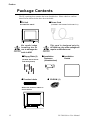
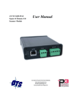
Package Contents
The PL's packing box contains the items listed below. Please check to confirm
that all items shown below have been included.
PL Unit
PL-5900T/PL-5901T
Be careful when
handling the PL
not to damage the
built-in HDD
Floppy Disks (3)
(PL5900 Series Driver
and Utility Disks)
Function Labels
Power Cord
(included in the PL5900-T11/PL5901-T11)
This cord is designed only for
AC100V use. Any other voltage will
require a different cord.
Installation
Fasteners
(4 brackets/set)
Installation
Gasket
CD-ROM (1)
Attach the function labels as
shown below.
12
PL-5900 Series User Manual
Preface
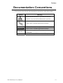
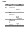
Documentation Conventions
The list below describes the documentation conventions used in this manual.
Symbol
Meaning
Indicates important information or procedures that must be
followed for correct and risk-free software/device operation.
Provides useful or important supplemental information.
*1
Indicates useful or important supplemental information.
Refers to useful or important supplemental information
1) , 2)
PL
PL-5900 Series User Manual
Indicates steps in a procedure. Be sure to perform these steps in
the order given.
Abbreviation for the PL-5900 Series Industrial Computers.
13
Memo
14
PL-5900 Series User Manual
1. PL System Design
2. Optional Items
Chapter
1
1.1
3. PL Series Panel Types
PL Basics
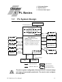
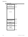
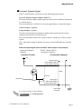
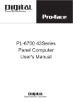
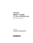
PL System Design
Screen Protection Sheet
PL Unit (DC24V)
Touch Panel
Display Unit (TFT Color)
Keyboard
Display Module
Reset Button
Front mount
FDD Unit
(RAS)
Set up by User
- 64MB Pre-installed (standard)
- Expansion slots
- PL-5900T: 2 PCI/ISA slots and 1ISA
(Using 2 PCI slots reduces ISA slots to 1)
Mouse
Printer
Exp. DIMM memory
(64MB)
Main Module
Keyboard
Peripheral Dev.
(Built-in)
RS-232C
3 ports
- PL-5901T: 1 ISA and 1 PCI slot
(Using 1 PCI slot reduces ISA slots to 0)
CD-ROM Drive/
Mirror Disk Unit
10BASE-T
100BASE-TX
LPT
(Built-in)
Pow er Unit
DC IN (19.2 to 28.8V)
(Built-in)
LAN Board
(Built-in)
Only to PL5900T
HDD/FFD Unit
(2.5”)
HDD/FFD
Expansion Slot
Cable Connection
Optional Items
Attached to Main Unit
Commercial Items
(Purchased by User)
The above system configuration illustrates the PL's internal design
and range of connectable peripherals. The user's actual configuration may differ.
PL-5900 Series User Manual
1-1
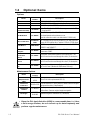
1.2
Optional Items
Options
DIM Module
Model
number
PL-EM500
HDD Unit
PL-HD220
FDD Unit
PL-FD500
FFD Unit
(Flash File Disk)
PL-FF200
CD-ROM Unit
PL-DK200
Mirror Disk Unit
PL-MD200HU01
LAN Board
DAX-IET02
RS-232C/RS-485
Adaptor
PL-RC500
Screen
Protection
Sheet
PL-CS001
Glare Resistant
Sheet
PL-NGS01
Mouse Emulator
V2
PL-TD000
Name
Description
SDRAM (DIMM) Provides 64MB of memory
10GB 2.5" HDD Unit (OS not included)
IBM PC Compatible 3.5” FDD unit (Attaches to front slot)
Flash File Disk Provides 20MB of memory, connected to IDE
I/F. Used as HDD.
IDE (ATAPI) compatible CD-ROM drive unit
– for development and maintenance use.
(special connection cable is included with CD-ROM unit)
IDE compatible mirror disk unit without OS for data protection
in case of HDD malfunction. Contains 2 2.5inch, 2.1GB drives.
NE2000 compatible board. Includes connectors for 10BASE-5,
10BASE-2 and 10BASE-T.
Converts an RS-232C interface to an RS-485 interface.
Connects to COM3.
Disposable, dirt-resistant sheet for screen protection. The
Touch Panel can be used through this sheet. (10 sheets/set)
Disposable, glare-resistant sheet for screen protection. The
Touch Panel can be used through this sheet. (10 sheets/set)
This software adds mouse and keyboard-like functionality to
the Touch Panel. (Windows® 95/Windows 98® only)
Maintenance Options
Name
Mirror Disk Unit
Replacement
HDD
Model
number
Description
PL-MD200Mirror Disk Unit’s replacement HDD (1).
MD01
Installation
Fasteners
GP070-AT01
Installation
Gasket
PL-WS500
Backlight
GP577TBL00-MS
Used to install the PL into a panel or cabinet. Same as original
equipment brackets. (4 brackets/set)
Used to prevent moisture from entering into the PL’s case from
the front face. Same as original equipment gasket.
Spare Backlight for maintenance. (2 bulbs/set)
• Since the PL’s hard disk drive (HDD) is a consumable item, i.e. it has
a finite usage lifetime, be sure to back up its data frequently and
perform regular maintenance.
1-2
PL-5900 Series User Manual
Chapter 1 - PL Basics
Commercially Available Products
Ite m
De scription
Insta lla tion Are a
Inserted into the
PL-5900T series units:
PL's expansion
-Slot 1boards can be up to 180 mm wide.
slots.
-Slots 2 and 3 can be up to 210 mm wide.
P CI/IS A Bus
PL5901T series units:
Com pa tible Boa rd
-Slot 1 PCI boards can be up to 180mm wide.
-Slot 1 ISA boards can be up to 210mm wide.
All boards can be up to 122 mm high.
The thickness of the devices attached to the face of
an expansion board can be:
- Slot 1 (both PL-5901T and PL-5900T) up to 13 mm
- Slot 2 (only PL-5900T) up to 18 mm
- Slot 3 (only PL-5900T) up to 13 mm
^
^
Width
Height
Attachment Direction
<Expansion Slot’s Width and Power Supply>
• Check that your expansion board’s “foot” matches the width of the
expansion slot. The PL-5900T unit's slot 2 can be up to 25 mm and
slot 3 can be up to 20 mm wide. Be sure the width of your expansion
board matches that of the intended slot.
<Commercially Available Boards>
• Certain commercially available boards may not be compatible with
Digital’s PL unit. Installing incompatible boards may result in either
damage to or failure of the PL and will void your warranty. Prior to
using those boards, be sure to contact your local PL distributor.
<PCI Bus>
• Within the entire range of PCI buses currently available on the
market, there may be certain devices which will not operate when
used with the PL. Prior to the use of any PCI Bus, be sure to contact
your local PL distributor.
PL-5900 Series User Manual
1-3
Chapter 1 - PL Basics
<ISA Bus>
• Only 8-bit access is supported. The driver software for the 16-bit
access board requires 8-bit access. Prior to installing commercially
available ISA Bus compatible boards, please contact your local PL
distributor.
ISA Bus Interface Usage Limitations
8-bit Operations
16-bit Operations
Normal Mode
I/O Access
Memory Access
O
O
X
X
DMA Mode
Memory Access
O
O
<Main Memory>
• Be sure to use only DIM modules manufactured by Digital. Installing
other DIM modules may result in either damage to the PL or a malfunction.
<IDE Interface>
• The PL is equipped with three IDE interfaces, two (2) of which can be used by
the HDD or FFD units (PL-5901T can use only one), and one (1) which can be
used by either the CD-ROM drive or the Mirror Disk unit. Physically, even
though up to three (3) IDE drive units can be connected at the same time, IDE
interface specifications require that a controller's simultaneous operation be
limited to a single master and slave unit, for a total of two devices.
The following chart shows the combinations available when using two IDE
units (PL-5901T can use only one).
MS
HDD Unit
FFD Unit
Mirror Disk Unit
CD-ROM Drive Unit
M
S
M
M
S
M
S
MS
S
S
M
S
M
M
S
S
M
M
S
MS: Combination of 2 units - Master or Slave, is possible.
M: Used only for Master.
S: Used only for Slave.
PL-5901T cannot use this combination.
<When using Commercial-type PC Peripheral Devices>
• Within the range of peripheral devices currently available on the
market there may be certain devices which will not operate correctly
when used with the PL. Prior to using any peripheral device, be sure
to contact your local PL distributor.
1-4
PL-5900 Series User Manual
Chapter 1 - PL Basics
1.3
PL Series Panel Types
DC24V Series Unit Model Numbers:
PL590* - T * *-DC24V
A
B
C DE
Item
Code
Meaning
A
PL590
PL-5900 Series Unit
3-slot type
1-slot type
TFT Color LCD display
Standard Model (no certification)
CE Marking, UL/cUL Approval
B
C
D
PL-5900 Series User Manual
0
1
T
1
4
1-5
Memo
1-6
PL-5900 Series User Manual
Chapter
2
2.1
1. General Specifications
4. PL Part Names and Features
2. Functional Specifications
5. PL Dimensions
3. Interface Connector Specifications
Specifications
General Specifications
2.1.1 Electrical
PL5900-T11, PL5901-T11
PL5900-T11
Input Voltage
Rated Voltage
Frequency
Allowable Voltage Drop
Power Consumption
Voltage Endurance
Insulation Resistance
PL5901-T11
AC100V
AC85V to AC132V
50/60Hz
1 cycle or less
(however, pause occurrences must be more than 1 second apart)
100VA or less
80VA or less
AC1500V 20mA for 1 minute
(between charging and FG terminals)
10M Ω or higher at DC500V
(between charging and FG terminals)
PL5900-T42-24V, PL5901-T41-24V
PL5900-T41-24V
Input Voltage
Rated Voltage
Allowable Voltage Drop
Power Consumption
Voltage Endurance
Insulation Resistance
PL-5900 Series User Manual
PL5901-T41-24V
DC24V
DC19.2V to DC28.8V
10 ms or less
(however, pause occurrences must be more than 1 second apart)
100W or less
80W or less
AC1000V 20mA for 1 minute
(between charging and FG terminals)
10M Ω or higher at DC500V
(between charging and FG terminals)
2-1
Chapter 2 - Specifications
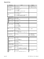
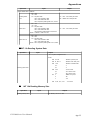
2.1.2 Environmental
Ambient Operating
Temperature
0oC to 45oC (with HDD attached: 5oC to 45oC)
Storage Temperature
Ambient Humidity
-10oC to 60oC
30%RH to 85%RH
Air Purity Level
0.1mg/m 3 or less (free of conductive particles and dust)
Atomosheric Pressure
Resistance
800 to 1114hPa (2000 meters or lower)
19.6m/s2 at 10Hz to 25Hz in X, Y, Z directions for 30 minutes
With HDD attached: 4.9m/s2
Vibration Resistance
With FD unit attached: 9.8m/s2
Noise Endurance
(via noise simulator)
Noise Voltage: 1500Vp-p
Pulse Width: 50ns, 500ns, 1µs
Rise Time: 1ns
Noise Immunity
2kV IEC 61000-4-4
Electrostatic Discharge
Immunity
6kV IEC 61000-4-2 Level 3
• When using any of the PL’s optional devices, be sure to check that
device’s specifications for any special conditions or cautions that
may apply to its use.
• Since the PL unit’s hard disk drive (HDD) is a consumable item, i.e. it
has a limited lifetime, be sure to back up its data regularly and prepare a spare HDD unit.
• The Hard Disk lifetime given here may be reduced due to unforeseen
environmental factors, however, generally speaking, at an operating
temperature of 20oC the disk should last for 20,000 hours (of operation) or approximately 5 years, whichever comes first.
• Using the Hard Disk in an environment that is excessively hot and/or
humid will shorten the disk’s usage lifetime. A maximum wet bulb
temperature of 29oC or less is recommended. The following data
shows equivalent conditions.
Temperature
o
at 35 C
no higher than 71%
at 40oC
no higher than 54%
o
at 50 C
2-2
Humidity
no higher than 33%
PL-5900 Series User Manual
Chapter 2 - Specifications
2.1.3 Structural
PL-5900T
PL-5901T
Grounding
Exclusive grounding: Use your country’s applicable standard.
Rating
Equivalent to IP65f (JEM 1030) *1
(Front face of installed unit)
External Dimensions
Weight
Cooling Method
W 311mm[12.99in.] x
H 271mm[10.76in.] x
D 130mm[6.38in.]
W 311mm[12.99in.] x
H 271mm[10.76in.] x
D 93mm[4.75in.]
(excluding projections)
(excluding projections)
6.0 kg (13.2 lb) or less
5.5 kg (12.1 lb) or less
Natural air ventilation
*1 The front face of the PL unit, installed in a solid panel, has been tested using conditions
equivalent to the standard shown in this specification . However even though the PL
unit’s level of resistance is equivalent to the standard, oils that should have no effect on
the PL can possibly harm the unit. This can occur in areas where either vaporized oils
are present, or where low viscosity cutting oils are allowed to adhere to the face of the
unit for long periods of time. If the PL’s front face protection sheet becomes peeled off,
these conditions can lead to the ingress of oil into the PL and separate protection
measures are suggested. Also, if non-approved oils are present, it may cause deformation
or corrosion of the front panel’s plastic cover. Therefore, prior to installing the PL be
sure to confirm the type of conditions that will be present in the PL’s operating environment.
PL-5900 Series User Manual
2-3
Chapter 2 - Specifications
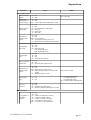
2.2
Functional Specifications
2.2.1 General
CPU
DRAM (SDRAM DIMM)
BIOS
Secondary Cache
Memory
512Kbytes (built-in)
VGA (640 x 480 dots)
VESA 16 colors/256 colors/16-bit color/32-bit color
Graphics
Video Memory
Type
Touch Panel Resolution
Interface
Serial
Printer
Keyboard
Mouse
*1
Interfaces
AMD-K6®-2 300MHz Processor
64MB Standard (2 DIMM sockets: max. 128MB)
AWARD PC/AT Compatible
USB
Network
RAS
Disk I/F
UMA (Unified memory architecture) type
Resistive Film (Analog)
1024 x 1024
COM4 : uses Mouse Emulator
COM1
D-Sub 9 pin (male)
RS-232C
COM2
D-Sub 9 pin (male)
(w/FIFO)
COM3
D-Sub 9 pin (male)
Centronics Standard (ECP/EPP equivalent) D-sub 25 pin, female
PS/2 Interface (mini DIN 6 pin, female)
PS/2 Interface (mini DIN 6 pin, female)
USB 1.0 Interface (side/front)
IEEE802.3 10BASE-T, 100BASE-T X
RAS Interface (D-sub 25 pin, male)
Front Access/ 2 modes/ 3.5 inch FD
FDD Unit
Side-mount 2.5 inch HDD I/F
PL-5900T: 2 slots
E-IDE
PL-5901T: 1 slot
Rear-mount Mirror Disk/CD-ROM (1 slot)
*1 Since MS-DOS® and Windows®95 OSR2 do not support this function, this feature
cannot be used if those OS types are installed in the PL.
2.2.2 Display
Display Type
Resolution
Dot Pitch
Effective Display Area
Display Colors
Contrast Control
Backlight
Backlight Lifetime
TFT Color LCD
640 x 480 pixels
0.33 mm x 0.33 mm
W211.2 mm x H158.4 mm
32-bit color
Not available
CFL (User replaceable)
50,000 hours or longer at an ambient temperature of 25oC.
(Until the backlight’s brightness dims to half of the original level.)
When it is time to change the backlight, please contact your local PL
distributor.
7.2 Replacing the Backlight.
2-4
PL-5900 Series User Manual
Chapter 2 - Specifications
2.2.3 Expansion Slots
PL5900T
Board Size
Slot Pitch
Board Thickness
180 x 122 mm 180 x 122 mm
210 x 122 mm 180 x 122 mm
None
210 x 122 mm
5V : 3A
12V : 0.6A
-5V : 0.1A
-12V : 0.1A
(total for 3 slots)
25 mm
20 mm
Less than 13 mm
Board Size
Slot Pitch
Board Thickness
-
Less than 13 mm
PCI
st
1 slot
nd
2 slot
rd
3 slot
Power
Supply
ISA
Less than 18 mm
Less than 13 mm
PL5901T
PCI
st
ISA
1 slot
180 x 122 mm 210 x 122 mm
Power
Supply
5V : 1A 12V : 0.5A
-5V : 0.1A -12V : 0.1A
For the 1st and 2nd slots either a PCI or an ISA type expansion board can be used.
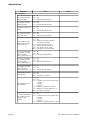
2.2.4 Clock (RTC) Accuracy
Clock(RTC) accuracy
+180 seconds per month
The PL unit's built-in clock (RTC) has a slight error. At the PL's specified ambient
temperature and with the power turned OFF the error is +180 seconds per month.
However, ambient temperature fluctuations and the age of the unit may increase
this error to +300 seconds per month. If the PL unit's RTC clock accuracy is vital
to system performance, regular adjustment of this clock is required.
PL-5900 Series User Manual
2-5
Chapter 2 - Specifications
2.3
Interface Specifications
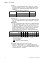
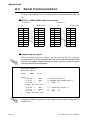
2.3.1 Printer Interface (LPT1)
D-sub 25 Pin (Female)
13 12 11 10 9
8
7
6
5
4
3
2
• O.D.: Open Drain
• T.S.: 3-state Input
• TTLIN: TTL Input
1
25 24 23 22 21 20 19 18 17 16 15 14
Screw Size: (4-40UNC): Inch Type
Electrical
Electrical Pin SPP/ECP Mode EPP Mode
Direction
Specif.
Specif. No.
Signal Name Signal Name
Pin
No.
SPP/ECP Mode
Signal Name
EPP Mode
Signal Name
1*1
STRB
WRITE
In/Output O.D/T.S 14 *1
AUTOFD
DSTRB
2
DATA0
DATA0
In/Output
3
DATA1
Direction
T.S
In/Output
DATA1
T.S
In/Output
In/Output
In/Output
In/Output
In/Output
In/Output
T.S
T.S
T.S
T.S
T.S
T.S
15
16
In/Output O.D/T.S
ERROR
ERROR
*1
INIT
INIT
In/Output O.D/T.S
*1
SLCTIN
GND
GND
GND
GND
GND
ADSTRB
GND
GND
GND
GND
GND
In/Output O.D/T.S
4
5
6
7
8
9
DATA2
DATA3
DATA4
DATA5
DATA6
DATA7
DATA2
DATA3
DATA4
DATA5
DATA6
DATA7
17
18
19
20
21
22
10
ACKNLG
ACKNLG
Input
TTL
23
GND
GND
11
12
13
BUSY
PE
SLCT
WAIT
PE
SLCT
Input
Input
Input
TTL
TTL
TTL
24
25
GND
GND
GND
GND
Input
TTL
*1 When using the printer interface in SPP mode, pins 1, 14, 16 and 17 become O.D.
When using ESC or EPP modes, these pins will change to T.S.
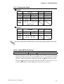
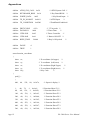
2.3.2 Keyboard Interface
(Both front and side)
Mini - DIN 6 pin (Female)
5
6
4
3
2
2-6
1
Pin No.
Signal Name
1
2
3
4
5
6
SHIELD
KEY DATA
NC
GND
+5V
KEY CLK
NC
GND
PL-5900 Series User Manual
Chapter 2 - Specifications
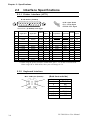
2.3.3 Mouse Interface
Mini - DIN 6 pin (Female)
5
6
4
3
1
2
Pin No.
Signal Name
1
2
3
4
5
6
SHIELD
Mouse DATA
NC
GND
+5V
Mouse CLK
NC
GND
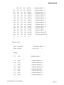
2.3.4 RS-232C Interface (COM1/COM2/COM3)
D-sub 9 pin (Male)
1
2
3
4
Pin No.
5
1
6
7
8
9
2
3
Screw Size: (4-40UNC): Inch Type
4
5
Signal
Name
CD
RXD
TXD
DTR
GND
Pin No.
6
7
8
9
Signal
Name
DSR
RTS
CTS
RI/5V
The GND terminal is the signal ground. Be sure to connect it with the
cable’s opposite side SG terminal.
No. 9 pin (RI/5V) is used by COM2 and COM3 only. If COM1 is used, the pin
becomes RI. The changeover from RI to 5V is set via the PL side face slide
switch.
2.4 PL Part Names and Features
Be sure to confirm what settings will be used by the other device and
set the dip switches accordingly. Failure to do so can result in a unit
malfunction or damage.
Whenever changing the PL dip switches, be sure to first turn the PL’s
power supply OFF. Failure to do so can cause a PL malfunction.
PL-5900 Series User Manual
2-7
Chapter 2 - Specifications
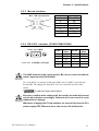
2.3.5 RAS Interface
D-Sub 25 pin (Male)
1
2
3
4
5
6
7
8
9
10 11 12 13
Screw Size: (4-40UNC): Inch
Type
14 15 16 17 18 19 20 21 22 23 24 25
Pin No.
Signal Name
Pin No.
Signal Name
1
GND
+5V
+12V
NC
RESET INPUT (+)
DIN 0 (+)
DOUT (-)
DOUT (+)
ALARM OUT (-)
ALARM OUT (+)
RESET INPUT (-)
DIN 0 (-)
DIN 1 (+)
14
GND
+5V
NC
NC
NC
NC
NC
LAMP OUT (-)
LAMP OUT (+)
NC
DIN1 (-)
NC
2
3
4
5
6
7
8
9
10
11
12
13
15
16
17
18
19
20
21
22
23
24
25
For detailed RAS Feature information,
Appendix 2 RAS Feature.
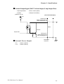
External Input Signal (Used for both DIN and Remote Set Input)
- External Power
: DC12V to DC24V
- Input Hold
: Hold Diode
- Isolation
: Used (Photo isolation)
(Interface Circuit)
(Connection Example)
+5V
DC12 to
24V
(External
Power)
R
6.8kΩ
1/10W
Input Port
Reset Input(+)pin 5
DIN0(+)pin 6
DIN1(+)pin 13
(12 to 24V)
Cable
Reset Input(-)pin 11
DIN0(-)pin 12
DIN1(-)pin 24
PC357
D-sub 25
pin
The power supply used for sink/source type input can use either polar or non-polar
connection.
2-8
PL-5900 Series User Manual
Chapter 2 - Specifications
External Output Signal (DOUT, Alarm Output, Lamp Output Port)
- Output Specifation
: DC24V 100mA (MAX)
- Isolation
: Used (Photo isolation)
(Interface Circuit)
(Connection Example)
+5V
DOUT(+)pin 8
Alarm Output(+)pin 10
Lamp Output(+)pin 22
R
Cable
SSTA06
Output Port
PC357
4.7Ω
External Power Output
+5V
:100mA (MAX)
+12V
:100mA (MAX)
PL-5900 Series User Manual
DOUT(-)pin 7
Alarm Output(-)pin 9
Lamp Output(-)pin 21
Dsub 25pin
connector
2-9
Chapter 2 - Specifications
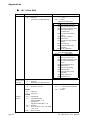
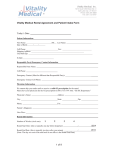
2.4
PL Part Names and Features
AB
C
<Inside
E
D
the front maintenance cover>
F
G
H
I
N
J
2-10
K
L
M
A: Display
Display output area. The built-in VGA controller supports PC compatible architecture.
B: Touch Panel
This high-resolution analog touch panel allows
you to configure a keyboard-less system.
C: Front Maintenance Cover
Open this cover to access the Keyboard I/F, Reset
Switch and connect the optional FDD unit.
D: Power Lamp LED
The status of the lamp changes according to the
alarm type detected by the RAS feature.
2-3-5 RAS Interface
E: Hard Disk Access LED (DISK)
The LED lights during accesses to the hard disk/flash
file disk.
F: FDD Front Face Blank Panel
Remove this cover to install the optional FDD Unit.
G: Keyboard Connector
A PS/2 compatible keyboard is connected here.
H: USB Connector (USB2)
To use the USB connector, you must install Windows
98 (SR2).
I: Hardware Reset Switch
J: IDE I/F Cover
To connect the optional CD-ROM drive unit (PLDK200), the Mirror Disk Unit(PL-MD200-HU01),
or RS-232C/RS-485 Adapter remove this cover
and use this connector.
K: FDD Rear Face Blank Panel
Remove this cover to install the optional FDD
Unit.
L: Power Switch
Turns the PL’s power ON or OFF.
M:Power Terminals
The PL’s AC100V/DC24V power cord terminals
are connected here.
N: Rear Maintenance Cover
Remove this cover to install the optional DIM module, or an expansion board.
PL-5900 Series User Manual
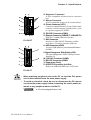
Chapter 2 - Specifications
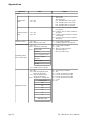
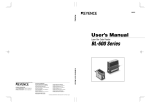
O
P
Q
Y
R
S
Z
T
U
V
W X
PL-5900T
O
P
Q
Y
R
S
Z
T
U
V
W X
O: Keyboard Connector
A PS/2 compatible keyboard can be connected
here.
P: Mouse Connector
A PS/2 compatible mouse can be connected here.
Q: Printer Connector (LPT1)
Centronics standard interface (D-sub 25 pin female
connector), which connects a parallel device, such
as a printer (supports ECP/EPP).
R: RS-232C Connector (COM1).
S: Ethernet Connector (10BASE-T, 100BASE-TX)
IEEE802.3 standard Ethernet interface.
T: RAS Connector
Interface for DIN, DOUT, Watchdog, and Remote Reset. (D-sub 25 pin male connector)
U: USB Connector (USB1)
To use the USB connector, you must install Windows
98 (SR2).
V:Signal Changeover Slide Switch (+5RI)
This switch changes the COM2/COM 9-pin current
from RI to 5V.
W: RS-232C Connector (COM2)
X: RS-232C Connector (COM3)
Y: Expansion Slot(s)
Z: HDD/FFD Expansion Unit Slot
Houses an additional HDD unit, or FFD unit.
PL-5901T
• When attaching peripheral units to the PL, be sure the PL’s power
cord is disconnected from the main power supply.
• To avoid an electrical shock, be sure to disconnect the PL’s power
cord from the power supply before connecting the cord’s power terminals or any peripheral devices to the PL.
4.3.1 Connecting the Power Cord
PL-5900 Series User Manual
2-11
Chapter 2 - Specifications
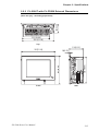
2.5
External Dimensions
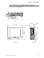
2.5.1 PL-5900T External Dimensions
80[3.15]
(Unit: mm [in.] - excluding projections)
251[9.88]
291.0[11.46]
Top
130[5.12]
271[10.67]
251.0[9.88]
14[0.55]
311[12.24]
Front
2-12
Side
PL-5900 Series User Manual
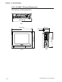
Chapter 2 - Specifications
2.5.2 PL-5900T with PL-FD500 External Dimensions
80[3.15]
(Unit: mm [in.] - excluding projections)
251.0[9.88]
291.0[11.46]
Top
130[5.12]
311[12.24]
271[10.67]
251.0[9.88]
14[0.55]
Front
PL-5900 Series User Manual
Side
2-13
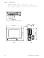
Chapter 2 - Specifications
2.5.3 PL-5900T with Mirror Disk Unit External Dimensions
80[3.15]
(Unit: mm [in.] - excluding projections)
158.0[6.22]
251.0[9.88]
291.0[11.46]
130[5.12]
Top
311[12.24]
50[1.97]
Front
2-14
251.0[9.88]
106.0[4.17]
271[10.67]
14[0.55]
Side
PL-5900 Series User Manual
Chapter 2 - Specifications
2.5.4 PL-5900T with PL-RC500 External Dimensions
80[3.15]
(Unit: mm [in.] - excluding projections)
91.0[3.58]
60.0 [2.36]
251.0[9.88]
291.0[11.46]
Top
130[5.12]
311[12.24]
PL-5900 Series User Manual
Side
31.0[1.22]
55.0 [2.17]
251.0[9.88]
14[0.55]
271[10.67]
Front
22[0.87]
2-15
Chapter 2 - Specifications
2.5.5 PL-5901T External Dimensions
(Unit: mm [in.] - excluding projections)
291.0[11.46]
Top
311[12.24]
93[3.66]
271[10.67]
251.0[9.88]
14[0.55]
Front
2-16
Side
PL-5900 Series User Manual
Chapter 2 - Specifications
2.5.6 PL-5901T with PL-FD500 External Dimensions
(Unit: mm [in.] - excluding projections)
111.0[4.37]
22.0[0.87]
291.0[11.46]
Top
93[3.66]
311[12.24]
30[1.18]
38 [1.50]
271[10.67]
251.0[9.88]
14[0.55]
Front
PL-5900 Series User Manual
Side
2-17
Chapter 2 - Specifications
2.5.7 PL-5901T with Mirror Disk Unit External Dimensions
(Unit: mm [in.] - excluding projections)
158.0[6.22]
291.0[11.46]
Top
93[3.66]
50[1.97]
311[12.24]
Front
2-18
251.0[9.88]
106.0[4.17]
271[10.67]
14[0.55]
Side
PL-5900 Series User Manual
Chapter 2 - Specifications
2.5.8 PL-5901T with PL-RC500 External Dimensions
(Unit: mm [in.] - excluding projections)
91.0[3.58]
60.0 [2.36]
291.0[11.46]
Top
93[3.66]
22[0.87]
311[12.24]
Front
PL-5900 Series User Manual
Side
31.0[1.22]
271[10.67]
55.0 [2.17]
251.0[9.88]
14[0.55]
2-19
Chapter 2 - Specifications
2.5.9 Panel Cut Dimensions
(Unit: mm [in.])
251.5
+1
[9.90
0
+0.04
]
0
an
th
ss
le -R3
4
291.5
+1
0
[11.48
+0.04
]
0
• Be sure the thickness of the panel is from 1.6 to 10 mm.
• All panel surfaces used should be strengthened. Especially, if high
levels of vibration are expected and the PL’s installation surface
(i.e. an operation panel’s door, etc.) can move (i.e.open or close)
due consideration should be given to the PL’s weight.
• To insure that the PL’s moisture resistance is maintained, be sure
to install the PL into a panel that is flat and free of scratches or
dents.
• Be sure all installation tolerances are maintained to prevent the
unit from falling out of its installation panel.
2-20
PL-5900 Series User Manual
1. Installation
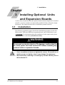
Chapter
3
Installing Optional Units
and Expansion Boards
A wide variety of optional units and expansion boards made by Digital can be installed
in the PL, as well as a number of commercially available PCI-bus or ISA-bus compatible boards. This chapter describes how to install these products in the PL.
3.1
Installation
The following explanation pages describe the installation procedures for the PL’s
DIM module, FDD unit, HDD unit, expansion boards, and CD-ROM drive unit.
For information about the installation of other option units, please
refer to those unit’s individual [Installation Guide].
WARNING
To prevent an electric shock or PL damage, confirm that the
PL unit’s power has been turned OFF before installing any
optional units or expansion boards.
• Use a screwdriver to loosen or tighten the screws. Be careful not to
tighten screws too tightly, since it may damage the equipment.
• Be careful when removing or inserting any screws that they do not
fall inside the PL.
PL-5900 Series User Manual
3-1
Chapter 3 - Installing Optional Units and Expansion Boards
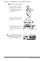
3.1.1 Removing the Rear Maintenance Cover
Be sure to handle the rear maintenance cover carefully, since it is made
of aluminum and is easily bent.
1) Unscrew the four (4) attachment screws
used to hold the rear maintenance cover
and half cover.
Rear Maintenance
Cover
2) Remove the rear maintenance cover by
lifting the cover in the direction shown.
3-2
PL-5900 Series User Manual
Chapter 3 - Installing Optional Units and Expansion Boards
3.1.2 Installing the DIM Module
Since DIM module sockets are fragile and break easily, be sure to install the DIM module carefully.
The PL comes with a single DIM module pre-installed. There is one more empty
socket that can be used to expand your PL unit’s memory. Use the following
procedure to install a second DIM module in that socket.
1) Install the DIM expansion module in
the empty socket.
Built-in DIM
Module
Empty Socket
2) Position the Alignment Grooves so
that they fit the Alignment Pins.
Alignment Grooves
Alignment Pins
3) Insert the DIM module into the DIM
module socket.
4) Push the DIM module down until the
ejector tabs lock.
5) Replace the rear maintenance cover
and the half cover and secure them
in place with their attachment screws.
To Remove the DIM Module
To remove a module, press down on the socket's ejector tabs to release the module.
PL-5900 Series User Manual
3-3
Chapter 3 - Installing Optional Units and Expansion Boards
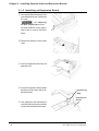
3.1.3 Installing the FDD Unit
The attachment procedures for the PL-5900T and the PL-5901T are different. The
following steps, up to 3), are the same. After that, refer to your unit’s specific
instructions.
1) Open the front maintenance cover
and remove the FDD front face blank
panel.
2) Close the front maintenance cover.
FDD front face blank panel
3) Remove the two (2) attachment
screws from the FDD rear face blank
panel and remove the cover.
3-4
FDD rear face blank panel
PL-5900 Series User Manual
Chapter 3 - Installing Optional Units and Expansion Boards
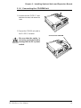
PL-5900T (3-Slot model)
4) Attach the FDD rear face blank panel
removed in step 3 to the FDD unit
and secure it with the two (2) attachm e n t
s c r e w s .
(Do not use the branket that comes
with the FDD Unit.)
5) Insert the FDD unit so that the PL and
FDD unit connectors are securely
connected.
6) Secure the FDD unit to the PL using
all four attachment screws. (Two (2)
FDD unit and two (2) PL bottom face
screws)
PL-5900 Series User Manual
3-5
Chapter 3 - Installing Optional Units and Expansion Boards
PL-5901T (1-Slot model)
4) Attach the branket that comes with
the FDD unit and secure it with the
two (2) attachment screws. ( Do not
use the FDD rear blank panel removed in step 3. )
5) Insert the FDD unit so that the PL and
FDD unit connectors are securely
connected.
6) Secure the FDD unit to the PL using
all four attachment screws. (Two (2)
FDD unit and two (2) PL bottom face
screws)
As this drawing shows, even when
the FDD unit is inserted completely, it will protrude slightly
from the back of the PL.
3-6
PL-5900 Series User Manual
Chapter 3 - Installing Optional Units and Expansion Boards
3.1.4 Removing/ Installing the HDD Unit
The following insertion/removal procedure is the same for the FFD unit.
Since the HDD unit is a precision instrument, be sure not to subject it
to excessive vibration or sudden shocks.
1) Remove the two (2) attachment
screws from the Expansion Slot
Cover. (Middle cover on the PL-5900)
Middle Expansion Slot
Attachment Screws
2) Grasp the HDD unit’s handle and pull
the unit slowly out of the PL. Be sure
you do not damage the unit.
3) Insert the new HDD unit into the PL’s
guideways and push it in until its rear
connector is securely connected.
4) Secure the unit in place with its two(2)
attachment screws.
PL-5900 Series User Manual
3-7
Chapter 3 - Installing Optional Units and Expansion Boards
3.1.5 Installing an Expansion Board
1) Unscrew the desired expansion slot’s
cover attachment screw, and remove
the cover.
3.1.1, Removing
the Rear Maintenance Cover
Unscrew the Blank Panel’s attachment screw to remove the Blank
Panel.
2) Remove the expansion slot’s duster
cover.
3) Insert the expansion board into the
expansion slot.
4) Secure the expansion board’s metal
positioning strip in place with its attachment screw.
Positioning
Strip
Attachment
Screw
5) Last, replace the rear maintenance
cover and half cover and secure them
in place with their attachment screws.
3-8
PL-5900 Series User Manual
Chapter 3 - Installing Optional Units and Expansion Boards
3.1.6 Connecting the CD-ROM Unit
1) Unscrew the two (2) IDE I/F cover
attachment screws, and remove the
cover.
2) Connect the CD-ROM unit cable to
the PL’s IDF I/F connector.
Connected to CD-ROM
Be sure that the cable is
securely connected before
turning ON the PL’s power
switch.
PL-5900 Series User Manual
3-9
Memo
PL-5900 Series User Manual
3-10
4-1 Installation Cautions
4-2 Installing the PL
Chapter
4
4-3 Wiring the PL
Installation and Wiring
This chapter explains how to install and wire the PL-5900 series units, as well as
the cautions required both before and during installation.
4.1
Installation Cautions
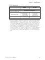
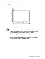
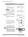
1) Temperature Cautions
The PL should be installed in a
vertical position, and forced air
cooling should be used, instead of
natural air circulation.
100mm
30mm
Also, be sure to confirm that the
area near the PL will be within the
allowable temperature range by
placing a temperature sensor in
the location shown in the left-side
drawing. If this area’s temperature
exceeds the allowed limit, a machine breakdown can occur.
Temperature Sensor
o
o
0 C to 45 C (without HDD unit)
o
o
5 C to 45 C (with HDD unit)
2) Installation Cautions
Be sure to install the panel in an
upright (vertical) position.
Also, be sure that the panel’s viewing angle is tilted no more than 30
degrees from parallel to the operator (i.e. directly in front).
OK
Vertical Installation
Horizontal Installation
No more than 30 degrees
of tilt
PL-5900 Series User Manual
4-1
Chapter 4 - Installation and Wiring
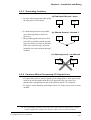
Vibration and Shocks
If the PL is moved when its enclosure doors are open, or while it is installed in a
rack equipped with caster wheels, the hard disk can receive excessive vibration or
jolting. Be especially careful at this time.
PL Configuration
Can Withstand
HDD
Up to 4.9m/s
FDD
Up to 9.8m/s
No drives
Up to 19.6m/s
2
2
2
• The Hard Disk Drive is precision equipment and should not be moved
or jolted . Especially when the PL is turned ON, even changing the
PL’s direction while it is on a table, or repositioning the unit should
not be performed, since it can lead to a hard disk crash or malfunction.
• When using a fan to cool the PL unit, be sure that the fan does not
point directly at any of the PL’s disk drive units, since it can lead to a
hard disk crash or malfunction.
4-2
PL-5900 Series User Manual
Chapter 4 - Installation and Wiring
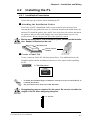
4.2
Installing the PL
4.2.1 Installation Procedures
Follow the steps given below when installing the PL.
Attaching the Installation Gasket
Even if the your PL’s Installation Gasket is not needed to prevent water from
entering the unit, the gasket also acts as a vibration absorber and should always be
attached. To install the gasket, place the PL face down on a soft surface and attach
the gasket to the rear side of the display face, in the plastic bezel’s groove (see
picture below). Be sure the grooved face of the gasket is vertical.
Before mounting the PL into a cabinet or panel, check that the Installation Gasket is attached to the unit.
PL Rear Face
Installation
Gasket
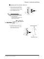
Create a Panel Cut
Create a panel cut for the PL, like that pictured here. Two additional items, the
installtion gasket and the installation fasteners are also required when installing
the PL.
2.5 PL Dimensions
Panel
Panel Cut
Area
• To obtain the maximum degree of moisture resistance, be sure to attach the PL to
a smooth, flat surface.
• The panel itself can be from 1.6 to 10.0 mm thick.
Strengthening may be required for the panel. Be sure to consider the
weight of the PL when designing the panel.
> < 1.6 - 10.0 mm
><
PL-5900 Series User Manual
4-3
Chapter 4 - Installation and Wiring
• To enhance the PL’s maintainability, operability and ventilation, allow at least
50 mm clearance between the PL and any other objects. (The clearance must be
large enough to allow you to insert or remove expansion boards and to attach
connectors.)
Unit: mm
• Avoid using the PL where the ambient temperature will exceed 45°C.
• Avoid placing the PL next to other devices that might cause overheating.
• Be sure that the panel’s viewing angle is tilted no more than 30 degrees from parallel to the operator (i.e. operator is directly in front).
• Keep the PL away from arc-generating devices such as magnetic switches and
non-fuse breakers.
• Avoid using the PL in environments where corrosive gases are present.
4-4
PL-5900 Series User Manual
Chapter 4 - Installation and Wiring
Installation
1) Insert the PL into the panel.
2) Insert the installation fastener hooks
into the four (4) installation fastener
holes on PL's top and bottom sides.
Installation Fastener Attachment Holes
3) Slide the installation fasteners to the
rear face.
PL-5900 Series User Manual
4-5
Chapter 4 - Installation and Wiring
4) Tighten the screws of the installation
fasteners. Be sure to tighten the four
screws in an even, crisscross pattern.
Do not use excessive force
when tightening the main
unit attachment screws. The
torque required to render it
waterproof is 0.5 N•m.
4-6
PL-5900 Series User Manual
Chapter 4 - Installation and Wiring
4.3
Wiring the PL
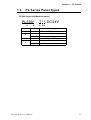
4.3.1 Connecting the Power Cord
Connect the PL’s power cord to the PL’s rear face power terminals.
(Side View)
PL5900-T11
PL5900-T41-24V
PL5901-T11
PL5901-T41-24V
Power Terminals
Power Switch
L
+
N
-
FG
FG
(screw size: M3)
PL-5900 Unit
+
Positive electrode
L
-
Negative electrode
Grounding Terminal connected to
the PL chassis.
N
FG
FG
AC Input Live Line
AC Input Neutral Line
Grounding Terminal connected to
the PL chassis.
Use the following steps when connecting the power cord to the PL’s power terminals.
WARNINGS
• To prevent an electric shock, be sure to turn the PL’s power
supply OFF before connecting the power cord terminals to
the PL.
• To prevent fires, electrical hazards and equipment damage,
be sure to use only the specified power supply voltage when
operating the PL.
1) Confirm that the PL’s power switch is
turned OFF. Then, remove the power
terminal’s transparent plastic cover.
L
N
Screws
FG
Transparent Cover
PL-5900 Series User Manual
4-7
Chapter 4 - Installation and Wiring
PL5900-T11, PL5901-T11
2) Loosen and remove the middle three
screws from the terminal strip. Align
the crimp terminals with each screw
hole, and tighten the screws.
Crimp Terminal Types :
V1.25-3, by J.S.T. or equivalent (JIS standard part number : RAV1.25-3)
• Crimp terminals must be the
same as shown below.
Black
L
N
FG
White
Green/Yellow
• The colors used in these
figures are for the cable
which came with the PL.
• This power cable is designed only for AC100V/
115V use. Any other
power level should use
its own specially designed cable.
3) Reattach the terminal strip’s transparent cover and secure it in place
with its attatchment screws.
Attachment Screws
L
N
FG
Transparent Cover
4-8
PL-5900 Series User Manual
Chapter 4 - Installation and Wiring
PL5900-T41-24V, PL5901-T41-24V
2) Loosen and remove the middle three
screws from the terminal strip. Align
the crimp terminals with each screw
hole, and tighten the screws.
+
+
FG
Crimp Terminal Types :
V1.25-3, by J.S.T. or equivalent (JIS standard part number : RAV1.25-3)
• Crimp terminals must be the
same as shown below.
3) Reattach the terminal strip’s transparent cover and secure it in place
with its attatchment screws.
FG
Attachment Screws
+
-
FG
Transparent Cover
PL-5900 Series User Manual
4-9
Chapter 4 - Installation and Wiring
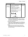
4.3.2 Power Supply Cautions
When connecting the PL unit’s AC power terminals, please be aware of the
following:
Constant
voltage
transformer
• If voltage fluctuations are expected to
vary beyond the specified range,
connect a constant voltage transformer.
Twisted-pair
cable
PL
FG
2-1 General Specifications
Twisted-pair
cable
• Use a low-noise power supply both
between the lines and between the PL
and its ground. If there is still excess
noise, connect an insulating transformer (noise-prevention type).
Insulating
transformer
Be sure any constant or insulating transformer used has a capacity of 200VA or
more.
AC 100V
PL
PL power
source
Main power
source
• Wire the power cords of the PL, I/O
devices, and power supply devices
separately.
• Attaching a ferrite core to the power
cord will improve noise immunity.
PL
FG
I/O power
source
I/O
device
Main power
source
PL
AC200V
• Isolate the main circuit (high voltage,
large current) line, I/O signal lines,
and power cord, and do not bind or
group them together.
PL power
sourceT1
T2
I/O power
source
I/O
device
I/O
device
• To prevent damage from lightning,
connect a lightning surge absorber.
• Ground the lightning surge absorber (E1) and the PL (E2) separately.
• Select a lightning surge absorber
which will not exceed the allowable circuit voltage, even when
the voltage rises to the maximum.
Power
device
Main circuit
power source
Twisted-pair cable
PL
AC
FG
E2
E1
Lightning surge
absorber
4-10
PL-5900 Series User Manual
Chapter 4 - Installation and Wiring
4.3.3 Grounding Cautions
(a) Dedicated Ground - best
• Set up a dedicated ground when using
the rear panel’s FG terminal.
• If a dedicated ground is not possible,
use a shared ground, as shown in
figure (b).
PL
*1
Other
device
(b) Shared Ground - allowed *1
PL
• The grounding point must be as close
to the PL as possible, and the grounding wires must be as short as possible.
If the wires must be long, use thick,
insulated wires and run them through
conduits.
Other
device
(c) Shared ground - not allowed
PL
Other
device
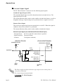
4.3.4 Cautions When Connecting I/O Signal Lines
• I/O signal lines must be wired separately from charged lines. If the power cord
needs to be wired together with the (I/O) signal lines for any reason, use
shielded lines and ground one end of the shield to the PL’s FG terminal.
• To improve noise immunity, attaching a ferrite core to the power cord is recommended.
*1 Use a grounding resistance of less than 100Ω and a 2mm2 or thicker wire, or your
country’s applicable standard. For details, contact your local PL distributor.
PL-5900 Series User Manual
4-11
Memo
4-12
PL-5900 Series User Manual
5-1 Setup Procedures
Chapter
5
5.1
5-2 System Parameters
System Setup
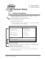
Setup Procedures
This chapter explains how to enter a PL unit's system settings, as well as the
cautions required both before and during set up.
The following settings are those pre-set at the factory.
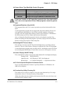
1) Connect a PS/2 keyboard to the PL.
2) Turn the PL unit's power ON.
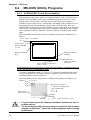
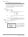
3) After the message "Press <DEL> to Enter SETUP" appears, press the [DEL]
key until the following screen is displayed.
CMOS Setup Utility - Copyright (C) 1984-2000 Award Software
Standard CMOS Features
PC Health Status
Advanced BIOS Features
Load Fail-Safe Defaults
Load Optimized Defaults
Advanced Chipset Features
Set Password
Integrated Peripherals
Save & Exit Setup
Power Management Setup
Exit Without Saving
PnP/PCI Configurations
ESC: Quit
F10
↑↓→←: Select Item
: Save & Exit Setup
Time,Date,Hard Disk Type...
KEYBOARD ACTION KEYS
A summary of the keyboard keys used to move through screens and make selections.
SYSTEM SETTING SELECTION AREA
Each of the titles (areas) listed refers to a system setting area.
4) Use the arrow keys to move the cursor to the desired selection and use the
[Enter] key to select an item.
PL-5900 Series User Manual
5-1
Chapter 5 - System Setup
5.2
System Parameters
Use the menu screen to select a System Item, and then enter the desired system
information. Each item's detailed settings are shown here.
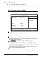
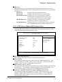
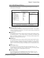
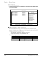
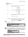
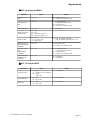
5.2.1 STANDARD CMOS FEATURES
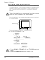
Select STANDARD CMOS FEATURES and the following screen will appear.
CMOS Setup Utility - Copyright (C) 1984-2000 Award Software
Standard CMOS Features
Date (mm:dd:yy):
Time (hh:mm:ss):
Thu, Aug 24 2000
11 : 15 : 14
Item Help
Menu Level
IDE Primary Master
IDE Primary Slave
Press Enter10056 MB
Press Enter None
Drive A
Drive B
1.44M, 3.5 in.
None
Video
Halt On
EGA/VGA
All, But Disk/Key
Base Memory
Extended Memory
Total Memory
Change the day, month,
year and century
640K
56320K
57344K
↑↓→←: Move Enter:Select +/-/PU/PD:Value F10:Save ESC:Exit F1:General Help
F5:Previous Values
F6:Fail-Safe Defaults
F7:Optimized Defaults
Date/Time
This data sets the PL's internal time and date.
Hours
:00 - 23
Minutes :00 - 59
Seconds :00 - 59
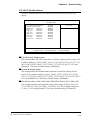
IDE Primary Master/ IDE Primary Slave
This display shows the capacity of the PL's IDE hard disk drive. Press [Enter] to
display the parameter setting menu.
"5.2.2 IDE Primary Master/IDE Primary Slave"
Drive A/Drive B
This setting determines the format used by the PL's internal floppy disk drive.
The available settings are [360K - 5.25in], [1.2M - 5.25in], [720K - 3.5in], [1.44M
- 3.5in.], [2.88M - 3.5in.] and [None].
The A: drive's [1.44M - 3.5in] and the B: drive is [None]. These selections are
factory set and recommended for most users.
Video
The selections for the screen (video) mode. The [EGA/VGA] and is recommended
for most users. The other available settings are [CGA40], [CGA80] and [Mono].
5-2
PL-5900 Series User Manual
Chapter 5 - System Setup
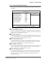
Halt On
Designates the type of processing that will be performed when an error occurs
during the Initial Start-Up Self Test. The [All But Disk /Key] and is recommended
for most users.
[All Errors]
:
Displays all errors and stops the unit.
[No Errors]
:
Displays all errors and does not stop the unit.
[All, But Keyboard]: Displays all errors, except for those related to
the keyboard, and stops the unit. If the User has
no keyboard connected, please use this setting.
[All, But Diskette]: Displays all errors, except for those related to
the disk drive (FDD), and stops the unit.
[All, But Disk/Key]: Displays all errors, except for those related to the disk
drive (FDD) and keyboard, and then stops the unit.
5.2.2 IDE Primary Master/IDE Primary Slave
Selecting IDE Primary Master or IDE Primary Slave from the Standard CMOS
Features menu brings up the following screen.
CMOS Setup Utility - Copyright (C) 1984-2000 Award Software
IDE Primary Master
IDE HDD Auto-Detection
Press Enter
IDE Primary Master
Access Mode
Auto
Auto
Capacity
10056 MB
Cylinder
Head
Precomp
Landing Zone
Sector
19485
16
0
19484
63
Item Help
Menu Level
To auto-detect the
HDD's size, head...on
this channel
↑↓→←:Move Enter:Select +/-/PU/PD:Value F10:Save ESC:Exit F1:General Help
F5:Previous Values
F6:Fail-Safe Defaults
F7:Optimized Defaults
IDE HDD Auto-Detection
This setting enables auto-detection of the IDE hard disk drive.
Access Mode
This setting determines the access mode of the PL's IDE hard disk drive. The
available settings are [CHS], [LBA], [Large], and [Auto]. The factory default
setting is [Auto] and is recommended for most users.
IDE Primary Master (Slave)
This setting sets the method for determining the parameter settings of the PL's IDE
hard disk drive. The available settings are [None], [Auto], and [Manual]. The
factory default setting is [Auto] and is recommended for most users.
Capacity/ Cylinder/ Head/ Precomp/ Landing Zone/ Sector
This setting determines the parameters of the PL's IDE hard disk drive. The
setting is required when the [IDE Primary Master (Slave)] is set to [Manual].
When the [IDE Primary Master (Slave)] is set to [None] or [Auto], the autodetected values will be used.
PL-5900 Series User Manual
5-3
Chapter 5 - System Setup
5.2.3 Advanced BIOS Features
Select Advanced BIOS Features from the Main Menu and the following screen
will appear.
CMOS Setup Utility - Copyright (C) 1984-2000 Award Software
Advanced BIOS Features
x
x
Virus Warning
CPU Internal Cache
External Cache
Quick Power On Self Test
First Boot Device
Second Boot Device
Third Boot Device
Boot Other Device
Swap Floppy Drive
Boot Up Floppy Seek
Boot Up NumLock Status
Gate A20 Option
Typematic Rate Setting
Typematic Rate (Chars/Sec)
Typematic Delay (Msec)
Security Option
OS Select For DRAM > 64MB
Report No FDD For WIN 95
Video BIOS Shadow
Cyrix 6x86/MII CPUID
Disabled
Enabled
Enabled
Disabled
Floppy
HDD-0
CDROM
Enabled
Disabled
Enabled
On
Fast
Disabeld
6
250
Setup
Non-OS2
No
Enabled
Enabled
Item Help
Menu Level
Allows you to choose
the VIRUS warning
feature for IDE Hard
Disk boot sector
protection. If this
function is enabled
and someone attempt to
write data into this
area, BIOS will show a
warning message on
screen and alarm beep
↑↓→←:Move Enter:Select +/-/PU/PD:Value F10:Save ESC:Exit F1:General Help
F5:Previous Values
F6:Fail-Safe Defaults
F7:Optimized Defaults
Virus Warning
This setting determines whether to display a warning when a write to the boot
sector is attempted. The available settings are [Enabled] or [Disabled]. The
factory default setting is [Disabled] and is recommended for most users.
CPU Internal Cache
This setting determines the usage of the CPU's internal cache memory. The
available settings are [Disabled] or [Enabled]. The factory default setting is
[Enabled] and is recommended for most users.
External Cache
This setting determines the usage of the external cache memory (L2). The available settings are [Disabled] or [Enabled]. The factory default setting is [Enabled]
and is recommended for most users.
Quick Power On Self Test
This setting determines whether the quick self test is performed when the power is
turned on. The available settings are [Disabled] or [Enabled]. The factory default
setting is [Disabled] and is recommended for most users.
5-4
PL-5900 Series User Manual
Chapter 5 - System Setup
First Boot Device/ Second Boot Device/ Third Boot Device
The selections for the search drive sequence of the operating system. The available settings are [Floppy], [HDD-0], [CDROM], [HDD-1], and [Disabled]. The
factory default settings are [Floppy] for the [First Boot Device], [HDD-0] for the
[Second Boot Device], and [CDROM] for the [Third Boot Device].
Boot other Device
This setting determines whether to allow the startup from devices other than those
selected as [First Boot Device], [Second Boot Device], and [Third Boot Device].
The available settings are [Disabled] or [Enabled]. The factory default setting is
[Enabled] and is recommended for most users.
Swap Floppy Drive
This setting swaps Drive A with Drive B for the recognition. The available
settings are [Disabled] or [Enabled]. The factory default setting is [Disabled] and
is recommended for most users.
Boot Up Floppy Seek
The setting specifies the function to check whether the floppy disk drive is installed upon the system boot-up process. The available settings are [Disabled] or
[Enabled]. The factory default setting is [Enabled] and is recommended for most
users.
Boot Up Numlock Status
This setting specifies the Numlock key status upon the startup. The available
settings are [On] and [Off]. The factory default setting is [On] and is recommended for most users.
Gate A20 Option
The available settings are [Normal] and [Fast]. When [Normal] is selected, the
Keyboard control will be employed to control Gate A20. When [Fast] is selected,
the Chipset will be employed. The factory default setting is [Fast] and is recommended for most users.
Typematic Rate Setting
The setting specifies the keyboard speed for the repeat process of the character.
The available settings are [Enabled] and [Disabled]. The factory default setting is
[Disabled] and is recommended for most users.
Typematic Rate (Chars/ Sec)
This setting specifies the actual typematic rate (repeated character input per
second) when the [Typematic Rate Setting] option is set to [Enabled]. The available settings are [6], [8], [10], [12], [15], [20], [24], [30]. The factory default
setting is [6] and is recommended for most users.
Typematic Delay (Msec)
When [Typematic Rate Setting] is set to [Enabled], this setting determines the
delay period until the initial repetition is started. (msec)=millisecond. The available settings are [250], [500], [750], and [1000]. The [250] selection is factory set.
PL-5900 Series User Manual
5-5
Chapter 5 - System Setup
Security Option
This setting designates the area to request a password. Select [Setup] or [System]
upon BIOS setup, or [System] upon system startup. This setting is NOT available
when the password is set using [Set Password] in the menu items. The factory
default setting is [Setup] and is recommended for most users.
OS Select For DRAM > 64MB
The available settings are [Non-OS2] and [OS2]. The factory default settting is
[Non-OS2] and is recommended for most users.
Report No FDD For WIN 95
This setting determines if the FDD node is reported by BIOS to WIN95. The
available settings are [No] and [Yes]. The factory default setting is [No] and is
recommended for most users.
Video BIOS Shadow
This setting determines whether to expand the Video BIOS ROM in RAM
(C0000-C7FFF). The factory default setting is [Enabled] and is recommended for
most users.
Cyrix 6x86/MII CPUID
This setting determines whether to send CPUID when Netware ver. 5.0 is used.
The available settings are [Enabled] and [Disabled]. The factory default setting is
[Enabled] and is recommended for most users.
5-6
PL-5900 Series User Manual
Chapter 5 - System Setup
5.2.4 Advanced Chipset Features
Select Advanced Chipset Features from the Main Menu and the following screen
will appear.
CMOS Setup Utility - Copyright (C) 1984-2000 Award Software
IDE Primary Master
Advanced DRAM Control 1
PCI Peer Concurrency
Read Prefetch Memory RD
Assert TRDY After Prefet
CPU to PCI Burst Mem. WR
AGP Aperture Size
Graphic Window WR Combin
System BIOS Cacheable
Video BIOS Cacheable
Memory Hole at 15M-16M
PCI Post Write Buffer
L2 Cache WT/WB Policy
Memory Parity Check
Press Enter
Enabled
Enabled
1 QWs
Enabled
64MB
Enabled
Enabled
Enabled
Disabled
Enabled
WB
Enabled
Item Help
Menu Level
↑↓→←:Move Enter:Select +/-/PU/PD:Value F10:Save ESC:Exit F1:General Help
F5:Previous Values
F6:Fail-Safe Defaults
F7:Optimized Defaults
Advanced DRAM Control 1
These selections display the DRAM setting. Press [Enter] to display the setting item
menu. The available setting is [100MHz] or [133MHz]. The factory default setting is
[100MHZ] and is recommended for most users.
PCI Peer Concurrency
This setting determines if the CPU will use L2/DRAM in parallel with PCI-to-PCI
access. The available settings are [Disabled] and [Enabled]. The factory default
setting is [Enabled] and is recommended for most users.
Read Prefetch Memory RD
This setting determines if the Memory Read command is used by the chipset to
prefetch data. The available settings are [Disabled] and [Enabled]. The factory
default setting is [Enabled] and is recommended for most users.
Assert TRDY After Prefet
This setting determines the TRDY assert data used for memeory processing by the
chipset. The available settings are [2QWs] and [1QWs]. The factory default
setting is [1QWs] and is recommended for most users.
CPU to PCI Burst Mem. WR
The setting determines whether the PCI write buffer is used. The write buffer is
not used when the [Disabled] option is selected. The available settings are [Disabled] and [Enabled]. The factory default setting is [Enabled] and is recommended for most users.
PL-5900 Series User Manual
5-7
Chapter 5 - System Setup
AGP Aperture Size
This setting specifies the memory used by the graphic board. The available settings are [4MB], [8MB], [16MB], [32MB], [64MB], [128MB], and [256MB].
The factory default setting is [64MB] and is recommended for most users.
Graphic Window WR Combin
This setting determines if the value designated in the GWBA register is accepted as the
Graphic Window Base Address. The available settings are [Disabled] and [Enabled].
The factory default setting is [Enabled] and is recommended for most users.
System BIOS Cacheable
This setting determines whether to cache the system BIOS. An OS that uses the
system BIOS operate faster. The available settings are [Enabled] and [Disabled].
The factory default setting is [Enabled] and is recommended for most users.
Video BIOS Cacheable
This setting determines whether to cache the video BIOS. The available settings
are [Enabled] and [Disabled]. The factory default setting is [Enabled] and is
recommended for most users.
Memory Hole At 15M-16M
This setting determines whether to designate the memory space from 15MB to
16MB as the buffer area for the ISA bus card. The available settings are [Disabled] and [Enabled]. The factory default setting is [Disabled] and is recommended for most users.
PCI Post Write Buffer
This setting determines if the PCI Post Write Buffer is controlled or not. The
available settings are [Disabled] and [Enabled]. The factory default setting is
[Enabled] and is recommended for most users.
L2 Cache WT/WB Policy
This setting determines degree of similarity between the L2 Cache and the System
DRAM. The available settings are [WT] and [WB]. The factory default setting is
[WB] and is recommended for most users.
Memory Parity Check
This setting determines whether parity checks are performed when parity protected
memory is used. The available settings are [Disabled] and [Enabled]. The factory
default setting is [Enabled] and is recommended for most users.
5-8
PL-5900 Series User Manual
Chapter 5 - System Setup
5.2.5 Integrated Peripherals
Select Integrated Peripherals from the Main Menu and the following screen will
appear.
CMOS Setup Utility - Copyright (C) 1984-2000 Award Software
Integrated Peripherals
SIS 540 OnChip PCI Device
SIS 950 SuperIO Device
USB Controller
USB Keyboard Support
Expansion mode Support
IDE HDD Block Mode
Init Display First
System Share Memory Size
Press Enter
Press Enter
Enabled
Enabled
Disabled
Enabled
PCI Slot
8 MB
Item Help
Menu Level
↑↓→←:Move Enter:Select +/-/PU/PD:Value F10:Save ESC:Exit F1:General Help
F5:Previous Values
F6:Fail-Safe Defaults
F7:Optimized Defaults
SIS 540 Onchip PCI Device
This setting enables the onboard Ethernet interface. Press [Enter] to display the
menu items for this setting. The available settings are [Enabled] and [Disabled].
The factory default setting is [Disabled] and is recommended for most users.
SIS 950 Super 10 Device
This setting configures the various onboard interfaces. Press [Enter] to display the
menu items for the setting.
"5.2.6 SIS 950 Super 10 Device"
USB Controller
This setting determines whether to use USB controller. The available settings are
[Disabled] and [Enabled]. The factory default setting is [Enabled] and is recommended for most users.
USB Keyboard Support
This setting determines whether to use the USB interface keyboard. The available
settings are [Disabled] and [Enabled]. The factory default setting is [Enabled] and
is recommended for most users.
Expantion mode Support
This setting determines if the VGA Expansion Mode is supported or not. Settings
available are [Disabled] and [Enabled]. The factory setting is [Disabled].
PL-5900 Series User Manual
5-9
Chapter 5 - System Setup
IDE HDD Block Mode
This setting determines whether to enable the Block Mode on the HDD supporting
the Block Mode. The available settings are [Disabled] and [Enabled]. The factory default setting is [Disabled] and is recommended for most users.
Init Display First
This setting determines the type of VGA card that is given priority - AGP or PCI.
The available settings are [PCI Slot] and [AGP]. The factory default setting is
[PCI Slot] and is recommended for most users.
System Share Memory Size
This setting determines the amount of system memeory used for video. The
available settings are [2MB], [4MB], [6MB], [8MB], [16MB], [32MB], [64MB]
and [Enabled]. The factory default setting is [8MB] and is recommended for most
users.
5-10
PL-5900 Series User Manual
Chapter 5 - System Setup
5.2.6 SIS 950 Super I0 Device
Select SIS 950 Super I0 Device from the Integrated Peripherals menu and the
following screen will appear.
CMOS Setup Utility - Copyright (C) 1984-2000 Award Software
SIS 950 SuperIO Device
Onboard FDC Controller
COM Port 1
COM Port 4
UART Mode Select
x UR2 Duplex Mode
Onboard Parallel Port
Parallel Port Mode
x ECP Mode Use DMA
COM Port 2
COM Port 2 Use IRQ
COM Port 3
COM Port 3 Use IRQ
Enabled
3F8/IRQ4
2E8/IRQ10
Normal
Half
3BC/IRQ7
SPP
3
2F8
IRQ3
3E8
IRQ11
Item Help
Menu Level
↑↓→←:Move Enter:Select +/-/PU/PD:Value F10:Save ESC:Exit F1:General Help
F5:Previous Values
F6:Fail-Safe Defaults
F7:Optimized Defaults
Onboard FDC Controller
This setting enables or disables the onboard floppy disk controller. The available
settings are [Disabled] and [Enabled]. The factory default setting is [Enabled] and
is recommended for most users.
COM Port 1
This setting determines the port address and the interrupt request number used by
the onboard serial port 1. The available settings are [Disabled], [3F8/IRQ4], [2F8/
IRQ3], [3E8/IRQ4], [2E8/IRQ10] and [Auto]. The factory default setting is [3F8/
IRQ4] and is recommended for most users.
COM Port 4
This setting determines the port address and the interrupt request number used by
the onboard serial port connected to the touch panel inside the PL. The available
settings are [Disabled], [3F8/IRQ4], [2F8/IRQ3], [3E8/IRQ4], [2E8/IRQ10] and
[Auto]. The factory default setting is [2E8/IRQ10] and is recommended for most
users
UART Mode Select
This setting determines the operation mode of the onboard serial port 2. The
available settings are [Normal], [IrDA], [ASKIR] and [SCR]. The factory default
setting is [Normal] and is recommended for most users.
UR2 Duplex Mode
This setting determines the communication mode when serial port 2 is set to
[IrDA] or [ASKIR] mode in [UART Mode Select]. The available settings are
[Full] and [Half]. The factory default setting is [Half].
PL-5900 Series User Manual
5-11
Chapter 5 - System Setup
Onboard Parallel Port
This setting determines the port address and the interrupt request number used by
the onboard parallel port. The available settings are [Disabled], [3BC/IRQ7],
[278/IRQ5] and [3BC/IRQ7]. The factory default setting is [378/IRQ7] and is
recommended for most users.
Parallel Port Mode
This setting determines the operation mode of the onboard parallel port. The
available settings are [SPP], [EPP], [ECP] and [ECP+EPP]. The factory default
setting is [SPP] and is recommended for most users.
ECP Mode Use DMA
This setting determines the DMA channel used in ECP mode. The available
settings are [1] and [3]. This setting is user-definable when the Parallel Port Mode
is set to [ECP] or [ECP+EPP].
COM Port 2
This setting determines the port address used by the onboard serial port 2. The
available settings are [Disabled], [3F8], or [2F8], [3E8] and [2E8]. The factory
default setting is [2F8] and is recommended for most users.
COM Port 2 Use IRQ
This setting determines the interrupt request number used by the onboard serial
port 2. The available settings are [IRQ15], [IRQ3], [IRQ4], [IRQ9], [IRQ10] and
[IRQ11]. The factory default setting is [IRQ3] and is recommended for most
users.
COM Port 3
This setting selects the port address used by the onboard serial port 3. The available settings are [Disabled], [3F8], [2F8], [3E8] and [2E8]. The factory default
setting is [3E8] and is recommended for most users.
COM Port 3 Use IRQ
This setting determines the interrupt request number used by the onboard serial
port 3. The available settings are [IRQ15], [IRQ3], [IRQ4], [IRQ9], [IRQ10] and
[IRQ11]. The factory default setting is [IRQ11] and is recommended for most
users.
5-12
PL-5900 Series User Manual
Chapter 5 - System Setup
5.2.7 Power Management Setup
Select Power Management Setup from the Main Menu and the following screen
will appear.
CMOS Setup Utility - Copyright (C) 1984-2000 Award Software
Power Management Setup
x
ACPI funcion
Video Off Option
Video Off Method
Watchdog Function
Watchdog Timer (sec)
PM Wake Up Events
Disabled
Susp,Stby -> Off
V/H SYNC+Blank
Disabled
5
Press Enter
Item Help
Menu Level
↑↓→←:Move Enter:Select +/-/PU/PD:Value F10:Save ESC:Exit F1:General Help
F5:Previous Values
F6:Fail-Safe Defaults
F7:Optimized Defaults
ACPI Function
This setting enables the ACPI function when ACPI-compatible peripherals are
connected. The available settings are [Enabled] and [Disabled]. The factory
default setting is [Disabled] and is recommended for most users.
Video Off Option
This setting determines the On/Off condition of the display. The available settings
are [Always On], [Suspend → Off], [Susp, Stby → Off], and [All Modes → Off].
The factory default setting is [Susp, Stby → Off] and is recommended for most
users.
Video Off Method
This setting determines the method to blank the display screen. The available
settings are [Blank Screen], [V/H SYNC+Blank], and [DPMS Supported]. The
[Blank Screen] selection blanks the display. The [V/H SYNC+Blank] blanks the
display and also suspends the Vertical/Horizontal synchronization signal of the
display. The [DPMS Supported] selection controls the operation when a CRT
that supports DPMS is used. The factory default setting is [V/H SYNC+Blank]
and is recommended for most users.
PL-5900 Series User Manual
5-13
Chapter 5 - System Setup
Watchdog Function
This setting enables or disables the Watchdog function. The available settings are
[Enabled] and [Disabled]. The factory default setting is [Disabled] and is recommended for most users.
Watchdog Timer (sec)
This setting determines the length of time of the Watchdog Timer. The available
setting range is between [5] and [255]. The factory default setting is [5]. This
setting is effective when the [Watchdog Function] is set to [Enabled].
PM Wake Up Events
This selection displays the settings for system wake up. Press [Enter] to display
the Parameter Setting menu.
"5.2.8 PM Wake Up Events"
5-14
PL-5900 Series User Manual
Chapter 5 - System Setup
5.2.8 PM Wake Up Events
Select PM Wake Up Events from the Power Management Setup Menu and the
following screen will appear.
CMOS Setup Utility - Copyright (C) 1984-2000 Award Software
PM Wake Up Events
IRQ [3-7,9-15],NMI
IRQ 8 Break Suspend
MACPME Power Up Control
PCIPME Power Up Control
KB Power ON Password
Power Up by Alarm
x Month Alarm
x Day of Month Alarm
x Time (hh:mm:ss) Alarm
Enabled
Disabled
Enabled
Enabled
Enter
Disabled
NA
0
0 0 0
Item Help
Menu Level
↑↓→←:Move Enter:Select +/-/PU/PD:Value F10:Save ESC:Exit F1:General Help
F5:Previous Values
F6:Fail-Safe Defaults
F7:Optimized Defaults
IRQ [3-7, 9-15], NMI
This setting determines if the system is reset when an allowed interrupt is detected. The available settings are [Disabled] and [Enabled]. The factory default
setting is [Enabled] and is recommended for most users.
IRQ 8 Break Suspend
This setting determines if the data required to trigger the power-saving suspend
mode is allocated to IRQ8 or not. The available settings are [Disabled] and
[Enabled]. The factory default setting is [Disabled] and is recommended for most
users.
MACPME Power Up Control
This setting determines if the PL starts via input from a LAN or not. The available settings are [Disabled] and [Enabled]. The factory default setting is [Enabled] and is recommended for most users.
PCIPME Power Up Control
This setting determines if the PL starts via input from a PCI card or not. The
available settings are [Disabled] and [Enabled]. The factory default setting is
[Enabled] and is recommended for most users.
KB Power ON Password
This setting defines the password when the system is powered-on by the keyboard
switch. Press [Enter] to display the setup menu.
PL-5900 Series User Manual
5-15
Chapter 5 - System Setup
Power Up by Alarm
This setting determines whether to set the timer to start automatic startup. The
available settings are [Disabled] and [Enabled]. The factory default setting is
[Disabled] and is recommended for most users.
Month Alarm
This setting selects the month when the system starts up automatically. The
available settings are [NA] and [1] through [12]. This function is available when
the [Power Up by Alarm] option is set to [Enabled].
Day of Month Alarm
This setting selects the day when the system starts up automatically. The available
settings are from [0] to [31]. This function is available when the [Power Up by
Alarm] option is set to [Enabled].
PM Wake Up Events
This setting specifies the time when the system starts up automatically. The
available settings are [00] to [23] for "hh" (hour), [00] to [59] for "mm" (minute),
and [00] to [59] for "ss" (second). This function is available when the [Power Up
by Alarm] option is set to [Enabled].
5-16
PL-5900 Series User Manual
Chapter 5 - System Setup
5.2.9 PnP/ PCI Configurations
Select PnP/ PCI Configuration from the Main Menu and the following screen
appears.
CMOS Setup Utility - Copyright (C) 1984-2000 Award Software
PnP/PCI Configurations
Reset Configuration Data
Disabled
Resources Controlled By
IRQ Resources
DMA Resources
Manual
Press Enter
Press Enter
PCI/VGA Pallet Snoop
PCI IRQ Actived By
Disabled
Level
Item Help
Menu Level
Default is Disabled.
Select Enabled to
reset Extended System
Configuration Data
ESCD) when you exit
Setup if you have
installed a new add-on
and the system
reconfiguration has
caused such a serious
conflict that the OS
cannot boot
↑↓→←:Move Enter:Select +/-/PU/PD:Value F10:Save ESC:Exit F1:General Help
F5:Previous Values
F6:Fail-Safe Defaults
F7:Optimized Defaults
Reset Configuration Data
This setting determines whether to initialize the ESCD (Extended System Configuration Data) used by Plug and Play devices when setup is complete. The
available settings are [Disabled] and [Enabled]. The factory default setting is
[Disabled] and is recommended for most users.
Resources Controlled By
This setting selects the method for allocating the Plug and Play I/0 Port, IRQ, and
DMA resources. The available settings are [Auto (ESCD)] and [Manual]. The
factory default setting is [Manual] and is recommended for most users.
IRQ Resources
This selection displays the configuration settings for devices assigned an IRQ.
Press [Enter] to display the setup menu.
5.2.10 IRQ Resources
DMA Resources
This selections displays the configuration settings for devices assigned a port
address. Press [Enter] to display the setup menu.
5.2.11 DMA Resources
PL-5900 Series User Manual
5-17
Chapter 5 - System Setup
PCI/VGA Pallet Snoop
This setting is used when a MPEG card and a VGA card are both installed in the
PL. The available settings are [Disabled] and [Enabled]. The factory default
setting is [Disabled] and is recommended for most users.
PCI IRQ Activated By
This setting defines the method of interruption used by the PCI slot. The available
settings are [Level] and [Edge]. The factory default setting is [Level] and is
recommended for most users.
5-18
PL-5900 Series User Manual
Chapter 5 - System Setup
5.2.10 IRQ Resources
Select IRQ Resources from the PnP/ PCI Configurations menu and the following
screen will appear.
CMOS Setup Utility - Copyright (C) 1984-2000 Award Software
IRQ Resources
IRQ-3 assigned to
IRQ-4 assigned to
IRQ-5 assigned to
IRQ-7 assigned to
IRQ-9 assigned to
IRQ-10 assigned to
IRQ-11 assigned to
IRQ-12 assigned to
IRQ-14 assigned to
IRQ-15 assigned to
Legacy ISA
Legacy ISA
PCI/ISA PnP
PCI/ISA PnP
PCI/ISA PnP
Legacy ISA
Legacy ISA
PCI/ISA PnP
PCI/ISA PnP
Legacy ISA
Item Help
Menu Level
Legacy ISA for devices
compliant with the
original PC AT bus
specification, PCI/ISA
PnP for devices
compliant with the
Plug and Play standard
whether designed for
PCI or ISA bus
architecture
↑↓→←:Move Enter:Select +/-/PU/PD:Value F10:Save ESC:Exit F1:General Help
F5:Previous Values
F6:Fail-Safe Defaults
F7:Optimized Defaults
IRQ-3 assigned to ~ IRQ-15 assigned to
This setting determines the type of device assigned to the IRQ. This function is
available when the [Resource Control By] option under the [PnP/ PCI Configurations] menu is set to [Manual].
[PCI/ISA PnP] .. Select to use a PnP-ready PCI or ISA card.
[Legacy ISA] .... Select to use a non-PnP ISA card.
The initial settings are as shown below.
Initial Value
IRQ-3 assigned to
IRQ-4 assigned to
IRQ-5 assigned to
IRQ-7 assigned to
IRQ-9 assigned to
PL-5900 Series User Manual
Legacy ISA
Legacy ISA
PCI/ISA PnP
PCI/ISA PnP
PCI/ISA PnP
Initial Value
IRQ-10 assigned to
IRQ-11 assigned to
IRQ-12 assigned to
IRQ-14 assigned to
IRQ-15 assigned to
Legacy ISA
Legacy ISA
PCI/ISA PnP
PCI/ISA PnP
Legacy ISA
5-19
Chapter 5 - System Setup
5.2.11 DMA Resources
Selecting DMA Resources from the PnP/PCI Configuration menu and the following screen will appear.
CMOS Setup Utility - Copyright (C) 1984-2000 Award Software
DMA Resources
DMA-0
DMA-1
DMA-3
DMA-5
DMA-6
DMA-7
assigned
assigned
assigned
assigned
assigned
assigned
to
to
to
to
to
to
PCI/ISA
PCI/ISA
PCI/ISA
PCI/ISA
PCI/ISA
PCI/ISA
PnP
PnP
PnP
PnP
PnP
PnP
Item Help
Menu Level
Legacy ISA for devices
compliant with the
original PC AT bus
specification, PCI/ISA
PnP for devices
compliant with the
Plug and Play standard
whether designed for
PCI or ISA bus
architecture
↑↓→←:Move Enter:Select +/-/PU/PD:Value F10:Save ESC:Exit F1:General Help
F5:Previous Values
F6:Fail-Safe Defaults
F7:Optimized Defaults
DMA-0 assigned to ~ DMA-7 assigned to
This setting determines the type of device assigned to the port address. This
function is available when the [Resource Control By] option under the [PnP/PCI
Configurations] menu is set to [Manual].
[PCI/ISA PnP]...Select to use a PnP PCI or ISA card.
[Legacy ISA]...Select to use a non-PnP ISA card.
The initial settings are as shown below.
Initial Value
DMA-0 assigned to
DMA-1 assigned to
DMA-3 assigned to
5-20
PCI/ISA PnP
PCI/ISA PnP
PCI/ISA PnP
Initial Value
DMA-5 assigned to
DMA-6 assigned to
DMA-7 assigned to
PCI/ISA PnP
PCI/ISA PnP
PCI/ISA PnP
PL-5900 Series User Manual
Chapter 5 - System Setup
5.2.12 PC Health Status
Select PC Health Status from the Main Menu and the following screen will
appear.
CMOS Setup Utility - Copyright (C) 1984-2000 Award Software
PC Health Status
CPU Warning Temperature
System Warning Temp
IN0(Vcore)
: Tolerance
IN1(3.3V)
: Tolerance
IN2( 5V)
: Tolerance
IN3( 12V)
: Tolerance
IN4(-12V)
: Tolerance
IN5( -5V)
: Tolerance
CPU Fan
: Tolerance
Power Fan
: Tolerance
:
:
:
:
:
:
:
:
:
Disabled
Disabled
Disabled
Disabled
Disabled
Disabled
Disabled
Disabled
Disabled
Disabled
Item Help
Menu Level
↑↓→←:Move Enter:Select +/-/PU/PD:Value F10:Save ESC:Exit F1:General Help
F5:Previous Values
F6:Fail-Safe Defaults
F7:Optimized Defaults
CPU Warning Temperature
This setting defines the CPU temperature at which a warning will be issued. The
available settings are [40°C/104°F], [45°C/113°F], [50°C/122°F], [55°C/131°F],
[60°C/140°F], [65°C/149°F], [70°C/158°F], [75°C/167°F], [80°C/176°F] and
[Disabled]. The factory default setting is [Disabled].
System Warning Temp
This setting defines the motherboard temperature at which a warning will be
issued. The available settings are [40°C/104°F], [45°C/113°F], [50°C/122°F],
[55°C/131°F], [60°C/140°F], [65°C/149°F], [70°C/158°F], [75°C/167°F], [80°C/
176°F] and [Disabled]. The factory default setting is [Disabled].
IN0 (Vcore)/ In1 (3.3V)/ IN2 (5V)/ IN3 (12V)/ IN4 (-12V)/ IN5 (-5V)
This setting determines the allowable range of the voltage of IN0 (Vcore)/ In1
(3.3V)/ IN2 (5V)/ IN3 (12V)/ IN4 (-12V)/ IN5 (-5V). The available settings are
[+/-4%], [+/-6%] and [Disabled]. The factory default setting is [Disabled].
PL-5900 Series User Manual
5-21
Chapter 5 - System Setup
CPU FAN
This setting determines the allowable range of CPU FAN speed. The available
settings are [±30%], [±50%] and [Disabled]. The factory default setting is [Disabled] and is recommended for most users.
POWER FAN
This setting determines the allowable range of the Power Fan speed. The available
settings are [±30%], [±50%] and [Disabled]. The factory default setting is [Disabled] and is recommended for most users.
5-22
PL-5900 Series User Manual
6-1
Floppy Disk Utility Programs
6-2
MS-DOS® Programs
Chapter
6
OS Setup
This chapter provides information about the set up of the PL’s MS-DOS® or
Windows® 95 operating systems.
6.1
Floppy Disk Utility Programs
The following additional program files are designed to run on the MS-DOS/
Windows®95 operating system. For details, please refer to the additional
“README” files.
README Files
File Name
READMEE.TXT
README.95E
PL-5900 Series User Manual
Contents
This file contains the latest detailed software program information.
Please be sure to read this file.
This file contains the latest detailed software program information.
Please be sure to read this file.
6-1
Chapter 6 - OS Setup
6.1.1 MS-DOS® Software
File name
ATPH59.EXE
CALIB59.EXE
KEYEM_PL.EXE
DISP.EXE
BLSET.EXE
EXTCOM.SYS
Description
Touch panel handler
Converts input from the touch panel in line with display panel
resolution (640 x 480). It is also compatible with Digital Panel
Computers of the PL-386 family. T his is not a mouse emulation
program.
Touch panel data calibration
By touching the specified position on the panel, the difference
between the logic value and measured value is corrected.
Furthermore, it is possible to create files with data based on
calibration results obtained here, to be used on the ATPH59.EXE
application.
This utility software displays a keyboard on the screen to allow touch
panel data input. (Only for Japanese version MS-DOS users)
Display On/Off program
Turns the display, including the backlight, either ON or OFF.
This utility software provides a means of turning the T ouch Screen
OFF when a backlight burnout is detected. This feature can help to
prevent accidents and injuries by preventing an accidental PL
operation mistake.
COM port driver (reception interrupt acknowledge). For details, see
the READMEE.TXT file on the same disk.
• Must be MS-DOS version 6.0 or later.
• Digital does not guarantee this software will work with any OS other than those
previously mentioned.
• This software is made for use with MS-DOS. Do not use it in a Windows® environment.
• For an explanation of the EXTCOM.SYS, and FUNCKEY.EXE applications, refer to their respective README.TXT file.
6.1.2
Windows® 95/Windows® 98 (SR2)
System Monitor/RAS Features
File Name
Contents
Program for entering monitoring parameter settings
PL_SMON.EXE System Monitor Program
PL_IOC.DLL
System Monitor/RAS API-DLL file (Windows ® 95/Windows ® 98 SR2)
PL_DLL.DLL
System Monitor/RAS Program DLL file (Windows ® 95/Windows ® 98 SR2)
PLSYSMON.VXD Hardware control driver (Windows ® 95/Windows ® 98 SR2)
PL_WPS.EXE
6-2
PL-5900 Series User Manual
Chapter 6 - OS Setup
Screen Saver Type Backlight Control Programs
File Name
Contents
Backlightcontrol.scr Screen saver main program
PL_BLIOC.DLL
BLCTRL.VXD
DISP.EXE
Backlight control API-DLL file (Windows ® 95/Windows ® 98 SR2)
Backlight control driver (Windows ® 95/Windows ® 98 SR2)
Backlight control program (Windows ® 95/Windows ® 98 SR2)
If the User installs an OS (operating system) other than that written
here, the correct operation of these utility programs cannot be guaranteed.
Keyboard Emulator (Keyclick32)
This program allows the User’s mouse operation to perform keyboard-like data
input.
Certain application programs do not support this keyboard emulator. Please test
each application individually to check if the keyboard emulator will operate
correctly. Also, this application cannot be used to enter Windows® 95/Windows®
98 (SR2) startup screen User Name and Password information.
Also, to change the Keyclick program’s font size a keyboard is required. For
details concerning the Keyclick program’s operation, simply click on the HELP
button to call up the program’s online help data.
Backlight OFF Screen Saver
This software is used to turn OFF the PL’s backlight after a specified period of
inactivity. The use of this feature will help to extend the life of the PL’s backlight.
Certain application programs may not allow the PL’s backlight to turn OFF. Please
test each program individually to check if the screen saver will operate correctly.
Screen Display ON/OFF Utility
This command line utility is used to turn OFF both the PL’s backlight and display.
Settings Used
DISP [ON/OFF]
Option Switch
ON: Displayed / OFF: Not Displayed
Return Value
0: Completed Normally / -1: Option Switch Error
PL Series Special Graphics Accelerator Driver
Uses a specialized hardware feature to speed up Windows® 95/Windows® 98
(SR2) screen displays.
Function Key Utility (Funckey 32)
This utility reserves an area of the PL screen for using function keys. For usage
instructions, refer to C:\Proface\Funckey’s Help feature.
(When the taskbar has been shifted to the bottom of the PL screen, the lower row
of function keys cannot be used)
PL-5900 Series User Manual
6-3
Chapter 6 - OS Setup
6.2
MS-DOS Ultility Programs
6.2.1
ATPH59.EXE (Touch Panel Handler)
With an analog touch panel, input is recognized within a 1024 x 1024 pixel area,
with the lower left-hand corner as the coordinate origin point. However, most
display panels use the upper left-hand corner as the origin point and have a
resolution of 640 x 480 pixels. Consequently, depending on the conditions of use,
the touch panel position and display position may not be the same. Here, the
ATPH59.EXE application solves this problem by converting input from the touch
panel into the corresponding display panel coordinates, allowing the use of application programs which use absolute coordinate input or area input from a touch
panel.
The relationship between touch panel coordinates and display coordinates is as
follows.
To u c h p a n e l c o o r d i n a t e s
(0, 0)
Function area
Virtual coordinates
(0, -40)
Display coordinates
Display coordinates
(0, 0)
(639,479)
Function area
Virtual coordinates
(639, 519)
To u c h p a n e l c o o r d i n a t e s
(1023, 1023)
Relationship between touch panel coordinates and display coordinates when using the PL-386 Series compatibility mode
To ensure compatibility with 16 x 14 (31 x 27 by double precision) touch panels
used on the Digital PL-386 family of Panel Computers, the TPH.EXE (PL-386
command) function can be used as is.
The relationship between touch panel coordinates and display coordinates is as
follows.
(1,1) (2,1)
(0,0)
(0,1)
(0,2)
Touch panel coordinates in
PL-386 family compatibility mode
Input coordinate range
X = 0 ~ 30
Y = 0 ~ 26
Display area in
640 x 480 mode
(30,24)
(30,25)
(30,26)
: To u c h p a n e l e f f e c t i v e a r e a
• A 2-point touch gives the midpoint coordinate between the two coordinate values.
• The touch panel handler cannot be used in conjunction with a mouse
emulator on Windows®. Cancel all resident programs before starting
up Windows®.
6-4
PL-5900 Series User Manual
Chapter 6 - OS Setup
Start-up
ATPH59 [Parameter] [[↵]]
* Parameters
-a<n>
Specifies the I/O base address of the touch panel’s SIO port.
Hexadecimal, Default: 2e8 (COM4)
n=
n
-q<n>
3f8
2f8
3e8
2e8
(COM1)
(COM2)
(COM3)
(COM4)
Specifies the interrupt level (IRQ) of the touch panel’s SIO port.
Default: 10 (COM4)
n= 4
(COM1)
3
(COM2)
11 (COM3)
10 (COM4)
-i<n>
Sets the software interrupt vector number when calling up functions.
Hexadecimal, Default: n=59
-r
Cancels the resident command.
-c <path name> Specifies the data file containing the calibrated value obtained
from CALIB59.EXE (touch panel data calibration). When
defaulted to, ATPH59.CAL of the current directory is used.
∗ Example atph59 -a2e8 -q10 -cc:\atph59.cal
Normally, only “atph59” is needed.
At startup, the following message will appear on the screen.
ouch Panel Handler ATPH59.EXE V
ersion X.XX C o p y Analog T
Touch
Version
right (c) 2000 Digital Electronics Corporation
Stay resident.
After startup, these commands reside in memory.
• If an error is generated because, for example, there is no file created
by the CALIB59.EXE application, the following message appears on
the screen, and the system will start up in a mode that does not
calibrate data.
W
ARNING!! Can’
WARNING!!
Can’tt open CAL file.
Stay resident.
• Unless properly calibrated, the display and touch panel input positions may not be the same.
PL-5900 Series User Manual
6-5
Chapter 6 - OS Setup
Functions
ATPH59.EXE calls up functions using a software interrupt (default: INT 59h).
For information on functions in the PL-386 compatibility mode, see pages 6-7 to 6-10.
INT 59h Function List
Function code
8100h
8101h
8102h
0200h
8500h
FE00h
8100h
Description
Touch panel input (unrestricted wait)
Touch panel input (immediate restore)
Touch panel non-destructive input
Input buffer clear
Touch panel status detection
Resident check
Touch panel input (unrestricted wait)
Returns coordinates of the area/position touched. Waits until data is input.
Input
AX = 8100h
Output
AH = 0: Successfully completed
BX = Y coordinate in 640 x 480 mode (-40 - 519)
DX = X coordinate in 640 x 480 mode (0 - 639)
CX = Number of valid input buffers on touch panel
8101h
Touch panel input (immediate restore)
Returns coordinates of the area/position touched. Immediately restored if nothing
is entered.
Input
AX = 8101h
Output
8102h
AH = 0: Input ON
1: Input OFF
BX = Y coordinate in 640 x 480 mode (-40 - 519)
DX = X coordinate in 640 x 480 mode (0 - 639)
CX = Number of valid input buffers on analog touch panel
Touch panel non-destructive input
Returns coordinates of the area/position touched. Does not update the touch panel
input buffer.
Input
AX = 8102h
Output
6-6
AH = 0: Input on
1: Input off
BX = Y coordinate in 640 x 480 mode (-40 - 519)
DX = X coordinate in 640 x 480 mode (0 - 639)
CX = Number of valid input buffers on analog touch panel
PL-5900 Series User Manual
Chapter 6 - OS Setup
0200h
Input buffer clear
Clears touch panel input buffers.
Input
AX = 0200h
Output
8500h
AH = 0: Successfully completed
Touch panel status detection
Returns touch panel status
Input
AX = 8500h
Output
AH = Status in 640 x 480 mode
Bit 1
Bit 0
Description
0
0
1
1
0
1
0
1
Area touched
Unchanged
Not available
Area released
* For an explanation on how to use the function, see “function 500h.”
FE00h
Resident check
When the ATPH59.EXE application resides in memory, returns a fixed message
and version.
Input
AX = FE00h
Output
AH = 0: Successfully completed
BL = ‘Y’
BH = ‘B’
CX = Version No.
Bit15
00
PL-5900 Series User Manual
^
ATPH59.EXE
ID code
^
Carry = Clear
^
^
1000
Version No.
6-7
Chapter 6 - OS Setup
Functions available in PL-386 Compatibility Mode
The following data details the functions available in the PL-386 compatibility
mode (when the user’s PL-386 application is used without further conversion,
updating or formatting).
INT 59h Function List
Function code
0000h
0100h
0101h
0102h
0300h
0400h
0401h
0402h
0500h
0000h
Description
Touch panel initialization
Touch panel input (unrestricted wait)
Touch panel input (immediate restore)
Touch panel non-destructive input
Coordinate code register
Coordinate code input (unrestricted wait)
Coordinate code input (immediate restore)
Coordinate code non-destructive input
Touch panel status detection
Touch panel initialization
Same as 0200h (Input buffer clear)
Input
AX = 0000h
Output
0100h
AH = 0: Successfully completed
Touch panel input (unrestricted wait)
Returns coordinates of the area/position touched. Waits until input is made.
Input
AX = 0100h
Output
0101h
AH = 0: Successfully completed
BH = Y coordinate range in PL-386 compatibility mode (0 - 26)
BL = X coordinate range in PL-386 compatibility mode (0 - 30)
CX = Number of valid data sets in touch panel input buffers
Touch panel input (immediate restore)
Returns coordinates of the area/position touched. Immediately restored after input
is made.
Input
AX = 0101h
Output
6-8
AH = 0: Input on (“1” when input is off)
BH = Y coordinate range in PL-386 compatibility mode (0 - 26)
BL = X coordinate range in PL-386 compatibility mode (0 - 30)
CX = Number of valid data sets in touch panel input buffers
PL-5900 Series User Manual
Chapter 6 - OS Setup
0102h
Touch panel non-destructive input
Returns coordinates of the area/position touched. Does not update touch panel
input buffer.
Input
AX = 0102h
Output
AH =0: Input present (No input = 1)
BH = Y coordinate range in PL-386 compatibility mode (0 - 26)
BL =X coordinate range in PL-386 compatibility mode (0 - 30)
CX = Number of valid data sets in touch panel input buffers
0300h
Coordinate code register
Registers code corresponding to the display coordinates.
Input
AX = 0300h
ES = Segment from coordinate code management table
DI = Offset from coordinate code management table
Output
AH = 0: Successfully completed
∗ Relationship between coordinate code management table and coordinate code
ES : DI
Coordinate code
management table
Coordinate & Coordinate code
Coordinate & Coordinate code
.
.
Coordinate & Coordinate code
∗ Coordinate Code Management Table Design
The coordinate code management table manages positions of multiple coordinate
code lists.
Number (n) of registered coordinate code lists
Offset of 1st coordinate code list
Segment of 1st coordinate code list
Offset of 2nd coordinate code list
Segment of 2nd coordinate code list
~
:
~
Offset of nth coordinate code list
Segment of nth coordinate code list
PL-5900 Series User Manual
6-9
Chapter 6 - OS Setup
∗ Coordinate Code List Design
The coordinate code list determines which code is returned when the touch panel
is pressed in a specific area. These coordinates specify the display coordinates.
Number (n) of registered coordinate codes
Display coordinate designation mode
Left side X coordinate of 1st area (X1)
Top side X coordinate of 1st area (Y1)
Right side X coordinate of 1st area (X2)
Bottom side X coordinate of 1st area (Y2)
Coordinate code of 1st area (code)
~
~
:
Left side X coordinate of nth area (X1)
Top side X coordinate of nth area (Y1)
Right side X coordinate of nth area (X2)
Bottom side X coordinate of nth area (Y2)
Coordinate code of nth area (code)
0400h
Coordinate code input (unrestricted wait)
Returns coordinates of the area/position touched and coordinate code. Waits until
data is entered.
Input
AX = 0400h
Output
AH
BH
BL
CX
DX
= 0: Successfully completed
= Y coordinate range in PL-386 compatibility mode (0 - 26)
= X coordinate range in PL-386 compatibility mode (0 - 30)
= Number of valid data sets in touch panel input buffers
= Coordinate code
To use function 0400h, it is necessary to first register the coordinate codes.
0401h
Coordinate code input (immediate restore)
Returns coordinates of the area/position touched and coordinate code. Immediately restored after data is entered.
Input
AX = 0401h
Output
AH
BH
BL
CX
DX
= 0: Input on (“1” when input is off)
= Y coordinate range in PL-386 compatibility mode (0 - 26)
= X coordinate range in PL-386 compatibility mode (0 - 30)
= Number of valid data sets in touch panel input buffers
= Coordinate code
To use function 0401h, it is necessary to first register the coordinate codes.
6-10
PL-5900 Series User Manual
Chapter 6 - OS Setup
0402h
Coordinate code non-destructive input
Returns coordinates of the area/position touched. Does not update the touch panel
input buffer.
Input
AX = 0402h
Output
AH
BH
BL
CX
DX
= 0: Input on (“1” when input is off)
= Y coordinate range in PL-386 family compatibility mode (0 - 26)
= X coordinate range in PL-386 family compatibility mode (0 - 30)
= Number of valid data sets in input buffers on touch panel
= Coordinate code
To use function 0402h, it is necessary to first register the coordinate codes.
0500h
Touch panel status detection
Returns the touch panel’s current status
Input
AX = 0500h
Output
AH = Status in PL-386 compatibility mode
Bit 1
Bit 0
Description
0
0
1
1
0
1
0
1
Area pressed
Unchanged
Not available
Area released
How to use function 0500h
Start
or
Function 0100h
Function 0101h
Processing until touch
panel area is released
Input?
Processing until touch
panel area is pressed
No
Yes
Function 0500h
Touch panel
area
held down
Bit 0
0
1
0
Bit 1
Coordinates
changed while
touch panel area
is pressed.
1
To next touch panel input
PL-5900 Series User Manual
6-11
Chapter 6 - OS Setup
6.2.2 CALIB59.EXE (Touch Panel Data Calibration)
By touching the specified position (upper left-hand corner or lower right-hand
corner) on the panel, the difference between the screen’s logical value and its
measured value is corrected. Furthermore, it is possible to create files with data
based on calibration results obtained here, to be used with the ATPH59.EXE
application (Touch Panel Handler).
Start-up
∗
CALIB59 [Parameter] [↵]
Parameter
-a<n>
Specifies the I/O base address of the touch panel’s SIO port.
Hexadecimal, Default: 2e8 (COM4)
n=
3f8
(COM1)
2f8
(COM2)
3e8
(COM3)
2e8
(COM4)
-q<n>
Specifies the interrupt level (IRQ) of the touch panel’s SIO port.
Default: 10
n= 3, 4, 10, 11
-c <path name> Specifies the data file containing the calibrated value obtained from
the CALIB59.EXE application (touch panel data calibration).
When defaulted to, ATPH59.CAL of the current directory is specified.
∗ Example CALIB59 -a2e8 -q10 -cc:\atph59.cal
• Normally, only “CALIB59” is needed.
Operation
Analog Touch Panel Calibration CALIB59.EXE Version
X.XX
Copyright(c) 2000 Digital Electronics Corporation
Calibration Mode
Touch upper left and lower right cornner of the screen.
[Enter] : Go to test mode.
[Esc] : Terminate program.
Upper left Lower right
(0000,0000) (0000,0000)
6-12
1) When the CALIB59.EXE application is opened up, the message
shown at the left will appear on
the screen, and two points will
light up, in both the upper lefthand and lower right-hand corners.
PL-5900 Series User Manual
Chapter 6 - OS Setup
Analog Touch Panel Calibration CALIB59.EXE Version
X.XX
Copyright (c) 2000 Digital Electronics Corporation
Calibration Mode
Touch upper left and lower right corner of the screen.
[Enter : Go to test mode.
[Esc] : Terminate program.
Upper left Lower right
(0039.0026) (0997.0988)
The measured value is
displayed on the screen.
2) Touch each point, in the order it appears.
• Do not touch both points simultaneously.
• Touch the panel exactly on the
lit up areas.
• The measured value is redisplayed if you touch the
panel again.
The difference between the logic value and the
measured value is obtained.
Terminate program without saving calibration data?(Y/N)
Analog Touch Panel Calibration CALIB59.EXE Version X.XX
Copyright (c) 199X Digital Electronics Corporation
Test Mode
[Enter] : Save calibration data and Exit.
[Esc] : Return to calibration mode.
To quit programming, press the [Esc]
key. Then, when the message shown on
the left appears, press the [Y] key. The
program will end without saving data.
Here, pressing the [N] key will return
you to the calibration mode.
↵] key.
3) Start up the “Test Mode” with the [↵
This mode tests the calibrated value to determine if it is correct or not.
The perimeter is OK if it is drawn along the path
you traced by finger. Otherwise, return to the
“Calibration Mode” and touch the lit up areas
again.
You can return to the “Calibration
Mode” with the [Esc] key.
Calibration data name? ATPH59.CAL_
4) If test results are OK, press the [Enter] key.
When the message shown at the left appears,
input the data file name and press the [↵] key.
When specifying the data file name for
the parameter (-C=[path name]) at the
CALIB59.EXE start-up, the program
ends without displaying the message
shown on the left.
PL-5900 Series User Manual
6-13
Chapter 6 - OS Setup
6.2.3 KEYEM_PL.EXE (Keyboard Emulator)
(Note: This program can only be used with the Japanese version of MS-DOS.)
This program graphically displays the keyboard on the screen, allowing keystroke
operation with the touch panel using the mouse to perform keyboard-like data
input. It also allows the user to define a key to any coordinates (external key
definition).
"External Key Definition" uses the touch panel coordinate mode compatible with Digital’s family of PL-386 Panel Computers.
Please place the function label included in the package to enhance the usability of
the Keyboard Emulator.
Display area
The structure and function of KEYEM_PL.EXE is as follows:
<The structure of KEYEM_.PL.EXE>
Application
Program
INT 16h
KEYEM_PL.DEXE
Display Data
HIMEM.SYS
ATPH59.EXE
Port 3
Touch Panel I/F
Keyboard BIOS
Keyboard I/F
• To use KEYEM_PL.EXE, HIMEM.SYS and ATPH59.EXE must be installed.
• Install the HIMEM.SYS file for the OS currently in use.
6-14
PL-5900 Series User Manual
Chapter 6 - OS Setup
Screen Display
The screen is split into two as shown below and the graphical keyboard is
displayed in the top or middle section (where the cursor is not residing).
Line 1
(UP)
Line 13
(MIDDLE)
Line 25
Touch [F8] to turn ON/OFF the
graphical keyboard.
(FEP)
• The display mode must be the DOS/V-compatible Japanese graphic
mode (72h). The graphical keyboard display supports the AX standard Japanese keyboard only. For the actual keyboard display
screen, refer to Appendix 5. "Keyboard Emulator Screens".
• This function cannot be used in conjunction with the NT-WIN mouse
emulator for Windows®. Cancel the resident program before starting up Windows®.
KEYEM_PL runs on top of ATPH59. To process touch input from
ATPH59 with a user application, exclusive control is necessary. Use
function A000h and A001h to control the keyboard emulator when
key input is necessary. Do not perform touch input processes during key input.
Configurations
When the graphical keyboard is displayed, XMS memory is used to temporarily
save the contents of the VRAM (63KB). If HIMEM.SYS is not installed, or if the
KEYEM_PL screen data save area is not reserved, this program will not start up.
When using this program in conjunction with programs that use expanded
memory, be sure to reserve enough memory.
<Sample Memory Map>
400000h
RAMDRIVE
SMARTDRV
Etc.
/
/
XMS AREA
/
/
KEYEM_PL
Screen Data Save
Area (63KB)
Kanji Character
Font Data for
Japanese Mode
(ca. 512KB)
100000h
PL-5900 Series User Manual
6-15
Chapter 6 - OS Setup
Start-up
KEYEM_PL [Parameter] [↵] or KEYEM_PL-r [↵]
* Parameters
-0[=][External Key Definition File]
Specifies the external key definition.
-2
Displays the graphical keyboard in 2- level mode.
-i<n>
tions.
Sets the software interrupt vector number when calling up funcHexadecimal, Default: n=59
-F
Displays the graphical keyboard in 16-level mode.
-T[=]n
Specifies the software interrupt vector number used for the Touch
Panel function calling.
(Hexadecimal, Default: n=59)
-r
Cancel the resident command.
• Normally parameter specification is not necessary. (Use the default).
At startup, the following message will appear on the screen.
Keyboard Emulator KEYEM_PL.EXE Version X.XX
Copyright (C) 2000 Digital Electronics Corporation
Stay resident.
After startup, these commands reside in memory.
Functions
KEYEM_PL.EXE includes the following functions and perform the function calls
using the software interrupt (INT 16h).
<INT16h Function List>
Function Code
00h
01h
02h
05h
10h
11h
12h
A000h
A001h
FE00h
6-16
Contents
Key input data read
Key input data check
Shift status read
Keyboard data write
Key input data read (AX keyboard)
Key input data check (AX keyboard)
Shift status read (AX keyboard)
Keyboard Emulation startup
Keyboard Emulation interrupt
Resident Check
PL-5900 Series User Manual
Chapter 6 - OS Setup
The following data details each function.
Function 00h
Key input data read
Reads the input key data.
Input
AH= 00hA
Output
AL= Primary code (character code)
AH= Secondary code (scan code)
Function 01h
Key input data check
Detects the data in the keyboard buffer.
Input
AH= 01h
Output
ZF= 0: Readable data in the keyboard buffer.
1: No readable data in the keyboard buffer.
AL= Primary code (character code)
AH= Secondary code (scan code)
Function 02h
Shift status read
Returns the status information of the special keys.
Input
AH= 02h
Output
AL= Shift status
Bit 7: Insert key
Bit 6: Caps Lock key
Bit 5: Num Lock key
Bit 4: Scroll Lock key
Bit 3: Alt key
Bit 2: Ctrl key
Bit 1: Shift Left key
Bit 0: Shift Right key
Function 05h
The key-in data writing
Writes the data for the CX register settings to the keyboard buffer as input from
the keyboard
Input
AH= 05h
CL= Primary code (character code)
CH= Secondary code (scan code)
Output
PL-5900 Series User Manual
AL= Status
0: Successfully completed
1: Aborted
(No available space in the keyboard buffer.)
6-17
Chapter 6 - OS Setup
Function10h
Keyinputdataread(AXkeyboard)
Reads the input key data. (The function is associated with the AX keyboard.)
Input
AH= 10h
Output
AL= Primary code (character code)
AH= Secondary code (scan code)
Function 11h
Key input data check. (AX keyboard)
Detects the data in the keyboard buffer.
(Function is associated with the AX keyboard).
Input
AH= 11h
Output
ZF= 0: Readable data in the keyboard buffer.
1: No readable data in the keyboard buffer.
AL= Primary code (character code)
AH= Secondary code (scan code)
Function 12h
Shift status read (AX keyboard)
Returns the status of the special keys.
Input
AH= 12h
Output
6-18
AL= Shift status
Bit 7: Insert key
Bit 6: Caps Lock key (lamp status)
Bit 5: Num Lock key (lamp status)
Bit 4: Scroll Lock key (lamp status)
Bit 3: Alt key
Bit 2: Ctrl key
Bit 1: Shift Left key
Bit 0: Shift Right key
AH= Shift status
Bit 7: Alt+Sys key
Bit 6: Caps Lock key (key status)
Bit 5: Num Lock key (key status)
Bit 4: Scroll Lock key (key status)
Bit 3: Alt Right key
Bit 2: Ctrl Right key
Bit 1: Shift Left key
Bit 0: Shift Right key
PL-5900 Series User Manual
Chapter 6 - OS Setup
Function A000h
Key emulation startup
Starts up the key emulation.
Input
AX= A000h
BL= 0: Clears the graphical keyboard
1: Displays the graphical keyboard in the opposite section to
the cursor location.
2: Displays the graphical keyboard in the top section of the
screen
3: Displays the graphical keyboard in the bottom section of the
screen
Output
None
WiththeBL=2andBL=3status,thegraphicalkeyboardisnotclearedautomatically by pressing the [Enter] key. When the cursor makes a vertical movement,
the change to the key-icon display position and display scroll check are not
performed. In this condition, the ON/OFF status of the key-icon display must
be controlled by the application.
FunctionA001h
Keyemulationinterrupt
Interrupts the key emulation.
Input
AX= A001h
BL= 0: Clears the graphical keyboard
1: Clears the graphical keyboard
(All keys are disabled.)
Output
None
Function FE00h
Resident check
When the KEYEM_PL.EXE application resides in memory, this function returns a
fixed message and version information.
Input
AX= FE00h
Output
AH=
BL=
BH=
CX=
0: Successfully completed
"Y"
"C"
Version number
Bit 15
00
1 0 0 0
KEYEM_PL.EXE
ID Code
Version No.
Carry= Clear
PL-5900 Series User Manual
6-19
Chapter 6 - OS Setup
The External Key Definition
This section explains how to designate a key to arbitrary coordinates with the
KEYEM_PL.EXE application.
(Left corner coordinate (X1), Upper corner coordinate (Y1), Right corner
coordinate(X2), Lower corner coordinate(Y2))
= the 1st key code [, the 2nd key code [, ...]]; comment line
Touch Panel Coordinates
(X1,Y1)
(X2,Y2)
• Designate the values with the touch panel coordinate range in PL-386 compatibility mode (0,1) ~ (30,25).
• If the designated coordinates overlap, the one defined first overrides the
other.
If more than two key codes are defined, they operate as if the input occurs in
sequence when the coordinated are pressed.
The key code can be defined using the following two methods.
1. Define the key code with 1 word.
1 word
High Bit
Low Bit
Primary Code (character code)
Secondary Code (scan code)
* The scan code can be omitted.
2. Define the key code with a character string surrounded by double
quotes.
The scan code here is assumed omitted.
• The key codes used in the KEYEM_PL.EXE are as follows.
0x0000: no key input
0x0007: Shift key
0x0001: graphical keyboard ON/OFF
0x0008: Ctrl key
0x0002: reserved
0x0009: Num/Symbol key
0x0003: reserved
0x000A: Japanese/English key
0x0004: Ctrl-Alt-Del
0x000B: ACT key
0x0005: Print key
0x000C: +/- key
0x0006: Pause key
6-20
PL-5900 Series User Manual
Chapter 6 - OS Setup
6.2.4
DISP.EXE (Display ON/OFF Program)
This application turns the display, including the backlight, ON or OFF.
Start-up
DISP ON [↵] or DISP OFF [↵]
The command’s execution result is set on the MS-DOS ERROR LEVEL. ERROR
LEVELS are as follows.
ERROR LEVEL
0
1
-1
6.2.5
Description
Successfully completed
Expansion BIOS (INT 5Fh) error
Other (command parameter, etc.) error
BLSET.EXE(BacklightBurnoutDetectionProgram)
This application detects if the backlight has burned out.
Start-up
BLSET ON [↵] or BLSET OFF [↵]
ON means the detection of the backlight burnout is enabled.
OFF means the detection is disabled.
For detection setting details, refer to Appendix 2 RAS Feature.
PL-5900 Series User Manual
6-21
Memo
PL-5900 Series User Manual
6-22
7-1 Regular Cleaning
7-2 Replacing the Backlight
Chapter
7
7.1
7-3 Periodic Maintenance Points
Maintenance and Inspection
Regular Cleaning
7.1.1 Cleaning the Display
When the display surface or frame become
dirty, use a soft cloth moistened with neutral detergent to wipe away any dust or
stains.
Neutral
detergent
Maintenance panel
Display
Do not clean the unit with thinner, organic
solvents, or strong acids.
Thinner
Organic solvent
Strong acid
Do not use sharp or hard objects, such as a
mechanical pencil or screwdriver, to push
on the display. This could damage the unit.
Protection sheet
PL-5900 Series User Manual
Use the screen protection sheet when using the PL in extremely dirty or dusty areas.
7-1
Chapter 7 - Maintenance and Inspection
7.1.2 Replacing the Installation Gasket
The installation gasket protects the PL and improves its water resistance. For
instructions on installing the PL’s gasket.
4-2 Installing the PL
A gasket which has been used for a long period of time may have scratches
or dirt on it, and could have lost much of its water resistance. Be sure to
change the gasket periodically (or when scratches or dirt become visible).
7.2
Replacing the Backlight
The PL’s backlight can be changed after it wears out. Follow the steps explained
below.
Please use the following table to identify which backlight model number to use when
ordering your backlight.
PL Type
Backlight Type
PL- 5900T
PL- 5901T
GP577RT-BL00-MS
WARNINGS
• Whenever changing the backlight, be sure the PL's power
cord has been disconnected and that the unit is cooled
down.
• When the PL's power cord is connected and the PL is ON,
high voltage runs through the wires in the backlight area—
do not touch them!
• When the PL's power has just been turned OFF, the backlight area is still very hot! Be sure to wear gloves to prevent being burned.
• Do not try to replace the backlight while the PL is installed
in a cabinet or panel. Remove the PL first, then begin the
backlight replacement procedures.
• Be careful when handling the backlight, since it is made of
glass and very fragile.
7-2
PL-5900 Series Users Manual
Chapter 7 - Maintenance and Inspection
Follow the steps given below to change the PL’s backlight. Be sure to wear cotton
gloves when performing this work to prevent burns.
1) Unplug the PL's power cord from the
main power supply and then disconnect the PL power cord terminals
from the PL's power terminal block.
Be sure to perform the backlight changeover on a flat,
level surface. This will prevent damage to the PL unit
and the accidental cutting of
any of its power cord terminals.
Power Cord
2) Remove the power cord.
3) Unscrew and remove the two (2) attachment screws from the right side
of the PL.
4) Unscrew and remove the two (2) attachment screws from the left side
of the PL.
5) Unscrew and remove the two (2) attachment screws from the bottom of
the PL.
PL-5900 Series Users Manual
7-3
Chapter 7 - Maintenance and Inspection
6) Slide the rear cover to the top side.
7) Lift up the rear face and remove it
from the front face.
8) Unscrew and remove the four (4) attachment screws securing the backlight.
Backlight
• Use a “0” sized Phillips
screwdriver to remove
the backlight attachment
screws.
• Be careful not to lose the
screws.
Backlight
• Be careful when removing the screws so that
they do not fall inside the
PL, since they may cause
the unit to malfunction.
9) Remove the connector from the inverter board.
10) Lift up the backlight and slowly pull
the unit out of the PL.
11) Insert the replacement backlight by
reversing the removal procedure.
Secure the replacement backlight
with the screws and insert the connector to the inverter board.
7-4
PL-5900 Series Users Manual
Chapter 7 - Maintenance and Inspection
• The PL’s backlights are
installed at the top and
bottom of the LCD panel.
Whenever you change a
backlight, be sure to
change both backlights.
• Be sure to insert the connector to the inverter
board and push it until its
rear connector is securely connected, or it
may cause damage.
12) Reattach the PL rear unit to the PL
front unit, using the PL’s guide slots,
i.e. reverse the procedure use to
separate them.
Be careful not to catch or cut any of
the PL’s internal cables while reattaching the two units.
13) Replace the four (4) attachment
screws removed in step 1) and 2).
PL-5900 Series Users Manual
7-5
7.3
Periodic Maintenance Points
Check the PL periodically to ensure it is in good working condition.
Ambient environment check
• Is the ambient temperature within the specified range?
(0°C to 45°C - without HDD unit, 5°C to 45°C - with HDD unit)
• Is the ambient humidity within the specified range (30%RH to 85 %RH) ?
• Is the atmosphere free of corrosive gas ?
Electrical specifications check
• Is the voltage adequate (AC85V to AC132V, 50/60 Hz or DC19.2V to
DC28.8V)?
Installation check points
• Is the connection cable firmly connected (not loose) ?
• Are any bolts or screws loose ?
• Are there any flaws or tears in the moisture resistant gesket ?
Display check
• Is the display bright enough ?
When the PL’s Standard Display’s backlight needs to be replaced, please contact your
local PL distributor.
7-6
PL-5900 Series User Manual
Appendices
A-1 Hardware Configuration
A-2 RAS Feature
Appendices
A-3 Serial Communication
A-4 Touch Panel Handler Program
A-5 BIOS List
A.1
Hardware Configuration
The following data explains the design of the I/O Map, Memory Map and Interrupt Map, as well as additional hardware design items including the RAS feature.
A.1.1 I/O Map
Address
0000H - 001FH
0020H - 003FH
0040H - 005FH
0060H - 006FH
0070H - 007FH
0080H - 009FH
00A0H - 00BFH
00C0H - 00DFH
00F0H - 00FFH
016CH - 016FH
01F0H - 01FFH
0200H - 0207H
0295H - 0296H
02E8H - 02EFH
02F8H - 02FFH
0378H - 037FH
03B0H - 03BBH
03BCH - 03BFH
03C0H - 03DFH
03E8H - 03EFH
03F0H - 03F7H
03F8H - 03FFH
AT System Device
System Device
DMA controller (8237)
Interrupt controller (8259A)
System timer (8254)
Keyboard (H8/3332)
Real-time clock, NMI mask
DMA bank register
Interrupt controller 2 (8259A)
DMA controller 2 (8237)
Numeric data processor
Used by Main Board
Hard disk (IDE)
Game I/O *1
Used by Main Board
Serial Port 4 (COM4): T ouch Panel
Serial port 2 (COM2) : General Use
Parallel port 2 (LPT2)
Video controller (VGA)
Parallel port 1 (LPT1) Printer
Video controller (VGA)
Serial port 3 (COM3): Reserved
Floppy disk controller
Serial port 1 (COM1) :General Use
Touch Panel
RS-485
*1 This device is not supported by the system, but is reserved as standard.
Depending on the arrangement of any connected Plug-and-Play devices, these features perform different functions/actions.
PL-5900 Series User Manual
App-1
Appendices
A.1.2 Memory Map
FFFFFFFFH
System ROM
FFFF0000H
~
~
~
~
Unused RAM
System ROM
00100000H
000E0000H
Expanded ROM Area
VGA BIOS
000CC000H
000C0000H
(Display Adaptor)
000A0000H
Unused RAM
640 KB
System Board DRAM
00000000H
App-2
PL-5900 Series User Manual
Appendices
A.1.3 Interrupt Map
Hardware Interrupt List
Description
NMI 0 Parity Error or I/O Channel Check
IRQ 0 Timer (in the Chipset)
IRQ 1 Keyboard
^
IRQ 2 Cascade from Controller 2
IRQ 3 Serial Port 2 (COM2): General Use Port
IRQ 4 Serial Port 1 (COM1): General Use Port
IRQ 5 Serial Bus Controller
IRQ 6 Floppy Disk Controller
IRQ 7 Parallel Port 1 (LPT1) : Printer Port
IRQ 8 Real T ime Clock
IRQ 9 ACPI Controller
IRQ 10
IRQ 11
IRQ 12
IRQ 13
IRQ 14
IRQ 15
Serial Port 4 (COM4): T ouch Panel (for
Standard monitor)
Serial Port 3 (COM3): General Use Port
Network Controller
Numeric Data Processor
Hard Disk (IDE)
Available for users
Depending on the arrangement of any connected Plug-and-Play devices, these features perform different functions/actions.
DMA Channel List
De scription
DMA 0
DMA 1
DMA 2
For 8-bit transmission
Floppy disk c ontroller
DMA 3
^
DMA 4
Cascade to controller 1
DMA 5
DMA 6
For 16-bit transmission
DMA 7
PL-5900 Series User Manual
App-3
Appendices
A.2
RAS Feature
A.2.1 PL's RAS Features
RAS, which stands for Reliability, Availability and Serviceability, is a device-level
monitoring function that provides a variety of features to improve the reliability of
your PL system.
Though the standard set of RAS features used will vary depending on the devices
used, the following features are used to provide Alarm Monitoring and External
Input Signal support.
Alarm Monitoring
External Input Signal
Power Voltage Alarm
Cooling Fan Alarm
Internal Temperature Alarm
Watchdog Timer Time Up
Mirror Disk Alarm *1
Backlight Burnout Detection
Touch Panel Alarm
Standard Signal Input (DIN 2 bit)
Remote Reset Input*2
Also, when either the one of the above mentioned alarms occurs, or an external
signal input is received, the following types of alarm processing output signals and
features are supported.
External Output Signal
Types of Processing (all units)
Standard Signal Output (DOUT 1 bit)
Alarm Output (1 point)
Lamp Output (1 point)
LED Indicator (3-state display – 1 point)
Pop-up Message Output
Buzzer Output
System Shutdown
Furthermore, using the PL’s System Monitor feature*3 (included in the PL’s software utility disk), allows the easy setting and control (Enable/Disable) of the
aforementioned Alarm Monitor and External Input Signals.
Last, the system monitor feature’s use of an Application Link Library (API-DLL)
allows it to also be used with other applications.
*1 When a Mirror Disk Alarm occurs and the standard RAS feature settings are used, the
alarm output is limited to the Mirror Disk unit’s LED indicator. (Alternately flashing orange
and green)
*2 The remote reset feature’s input can be either enabled or disabled, the alarm output setting
cannot be set to trigger a forced system reset.
*3 For System Monitor Feature details, refer to the accompanying Driver and Utility disk.
Chapter 6 - Setting up Your PL OS
App-4
PL-5900 Series User Manual
Appendices
A.2.2 RAS Feature Details
Alarm Monitoring
Power Voltage Alarm
Monitors the condition of the PL’s internal and CPU power.
Cooling Fan Alarm
Monitors the condition of the PL’s internal power and CPU cooling fans.
Internal Temperature Alarm
Monitors the PL’s internal and CPU vicinity temperatures.
The degree of monitoring (3 levels) and the enabling or disabling of the above
three items is performed via the System Setup Area’s settings.
For detailed information about the monitoring level settings,
5.2.12 PC Health Status
This utility can also be used to enable or disable the above mentioned features, as
well as designate what type of processing is to be performed.
Watchdog Timer Time Up
This feature alternately writes Time Up Count values from the CPU to the RAS
feature’s special programmable timer and then periodically clears them, which
provides a means of monitoring the CPU’s performance. If the clearing of this
count value is stopped, the timer will overflow and an alarm will be detected. The
System Monitor utility can be used to enable or disable this feature, as well as
designate what type of processing is to be performed.
5-2-7 Power Management Setup
Mirror Disk Alarm
Whenever a disk crash, or other alarm event occurs to the optional Mirror Disk
unit, this unit’s LED indicator will flash (either orange or green) to indicate there
is a problem.
This unit’s error detection occurs independently of and cannot be set by the RAS
feature.
Backlight Burnout Detection
This feature allows you to detect when the PL's backlight burns out.
When this feature is enabled and a backlight burnout occurs, touch operation will
be disabled and PL's front panel LED indicator will blink. The factory setting is
"Enabled" and is recommended to prevent accidental touch panel operation. This
setting is controlled via the MS-DOS utility BLSET.EXE.
Touch Panel Alarm
This feature detects a Touch Panel alarm. When this alarm occurs, the PL unit's
front panel LED indicator will blink.
PL-5900 Series User Manual
App-5
Appendices
External Input Signal
The PL’s RAS interface connector uses the following input signals.
Standard Signal Input (DIN)
This standard digital input is used for alarm detection in external devices. The
input signal uses two bits.
The System Monitor utility can be used to enable or disable this feature, as well as
designate what type of processing is to be performed once a signal is received.
Remote Reset Input
This is the reset signal sent from an external device to the PL. When this signal is
enabled, a forced reset of the PL is performed.
The System Monitor utility can be used to enable or disable this feature
External Input Signal (for both DIN and Remote Reset Input)
- External Power
DC12V to DC24V connections are possible
- Input Protection
Protection Diode
- Isolation
Used (photo-isolation)
(Interface Circuit)
(Connection Example)
(Interface Circuit)
(Connection Example)
+5V
DC12 to
24V
(External
Power)
R
6.8kΩ
1/10W
Input Port
Reset Input(+)pin 5
DIN0(+)pin 6
DIN1(+)pin 13
(12 to 24V)
Cable
Reset Input(-)pin 11
DIN0(-)pin 12
DIN1(-)pin 24
PC357
D-sub 25
pin
- The Power supply used for sink/source type input can use either polar or
non-polar connection.
- For connection pin location details,
2.3.5 RAS Interface
App-6
PL-5900 Series User Manual
Appendices
External Output Signal
The PL’s RAS interface connector uses the following output signals.
General Purpose Signal Output (DOUT)
This general purpose digital output signal provides system condition information
to external devices.
The System Monitor’s API-DLL are used by applications to control this signal.
Alarm Output (1 point)
Lamp Output (1 point)
The above mentioned general purpose digital output signals provide system
condition information to external devices.
The System Monitor utility can be used to enable or disable any of these output
signals.
Also, when alarm output is enabled, the orange colored LED indicator will also
blink.
External Output Signal (used for DOUT, Alarm Output, Lamp Output)
- Output Specification
DC24V 100mA (MAX)
- Isolation
Used (photo-isolation)
(Interface Circuit)
(Connection Example)
+5V
DOUT(+)pin 8
Alarm Output(+)pin 10
Lamp Output(+)pin 22
R
Cable
SSTA06
Output Port
PC357
4.7Ω
DOUT(-)pin 7
Alarm Output(-)pin 9
Lamp Output(-)pin 21
Dsub 25pin
connector
For connection pin location details,
2.3.5 RAS Interface
PL-5900 Series User Manual
App-7
Appendices
Types of Processing (all units)
The PL provides system condition information via the following methods.
LED Indicator (3-state display – 1 point)
In addition to indicating if the unit’s power is ON or OFF, the 3-state LED indicator (power lamp) provides the following system condition information.
Color
Green
Orange
Flashing
Red/Green
System Condition
Normal Operation (Power ON)
RAS has detected a system
alarm.
Mirror Disk and Backlight alarms
have occurred
Output Created
None
The alarm output set in the
system monitor is enabled.
Any TOOL settings are
enabled.
Flashing
Mirror Disk Alarm has occurred
Orange/ Green
None
Flashing
Orange/Red
Any TOOL settings are
enabled.
Backlight Alarm has occurred
Pop-up Message Output
This feature uses the Windows® system’s pop-up message feature to indicate that
an alarm has occurred.
Buzzer Output
This feature uses the PL’s internal speaker to indicate the system’s condition.
System Shutdown
This feature shuts down the PL’s OS (Windows® 95/ Windows® 98 Second
Edition). The System Monitor utility can be used to enable or disable this feature.
App-8
PL-5900 Series User Manual
Appendices
A.2.3 RAS Feature Overview
System Setup
Alarm Level Detection
Settings
+
Enable/Disable Settings
(Voltage, Fan RPM, Temp.)
Power Alarm
Cooling Fan
RPM Alarm
Int. Temp. Alarm
CPU
Clear
Watchdog
Timer
System Monitor
APIDLL
User Application
Alarm
Shutdown
Processing
Alarm
Alarm
Pop-Up
Message
Time Up
Enable
Disable
Settings
Outout
Settings
Buzzer Output
General
Purpose Signal
RAS
Output
Connector
Lamp Output
System Monitor Timeout
Time Setting
General
Purpose Input
Alarm Output
RAS
Connector
2 Bit
Remote Reset
Input
Hardware Reset
LED
Touch Panel
Alarm
Lights Orange
Lights Orange
Mirror Disk
Alarm
Flashes Orange/
Green
Power ON
Backlight Alarm
Turn ON/
OFF
LightsGreen
Flashes Orange/
Red
Setup TOOL
PL-5900 Series User Manual
App-9
Appendices
A.3
Serial Communication
This section explains how to perform serial communications with the
PL.
RS-232C (COM1/COM2) Cable Connections
<Example 1>
PL
1
2
3
4
5
6
7
8
9
<Example 2>
Dsub 25-pin
CD
RD
TD
DTR
GND
DSR
RTS
CTS
RI
1
2
3
4
5
6
7
8
20
FG
SD
RD
RTS
CTS
DSR
SG
CD
DTR
PL
1
2
3
4
5
6
7
8
9
CD
RD
TD
DTR
GND
DSR
RTS
CTS
RI
Dsub 25-pin
1
2
3
4
5
6
7
8
20
FG
SD
RD
RTS
CTS
DSR
SG
CD
DTR
Sample output program
Below is a sample program for sending 1 character from the RS-232C connector.
Because the PL uses an AT-compatible BIOS, the serial communication BIOS (INT
14 h) does not support communications by interrupt. Therefore, install a reception
interrupt function in the application.
#include <stdio.h>
#include <dos.h>
union
REGS
ir,or;
main( ){
ir.h.ah =
0x00 ;
/* Initialization */
ir.h.al =
0xe3 ;
/* 9600bps,8bit,NONE,1stop */
ir.x.dx =
0 ;
/*
COM1
*/
int86 (0x14,&ir,&or) ;
ir.h.ah =
0x01 ;
/* 1 character output */
ir.h.al =
0x32 ;
/*
‘2’
*/
ir.x.dx =
0 ;
/*
COM1
*/
int86 (0x14,&ir,&or) ;
}
Changing commands or parameters also changes function (mode setting, data reception, etc.).
App-10
PL-5900 Series User Manual
Appendices
A.4
Touch Panel Handler
The following sample program was created with the ATPH59.EXE (Touch Panel
Handler) application.
Sample Program made with the Touch Panel Handler
Compiler Method
cl sample.c
If not adding GRAPHICS.LIB to SLIBCE.LIB, add / l i n k
graphics.lib.
F1
F2
F3
F4
F5
F6
F7
F8
Please press one of the touch panel keys.
Pressing either “Z” or on the square shown to
the right, will quit this program.
“Quit” key
1
2
3
4
5
6
7
8
9
0
.
+
B S ENT
Function Key
area
This sample program is designed to perform processing based on the touch panel input
received from either the upper or lower function keys, or the screen’s designated Quit key area.
/* This sample program is used by the ATPH59.EXE touch panel handler.
* Input can be performed by pressing on designated areas of the screen.
* Before starting this program, be sure to start the ATPH59.EXE program
*/
#include <stdlib.h>
#include <stdio.h>
#include <dos.h>
#include <graph.h>
#include <conio.h>
PL-5900 Series User Manual
App-11
Appendices
#define ATPH_SYS_CALL 0x59
#define KEYBOARD_BIOS
#define WRITE_DATA
/* ATPH System Call */
0x16
/* Key Board BIOS
0x05
*/
/* Key Board Input */
#define TP_IN_NOWAIT
0x8101
/* ATPH Input
#define TP_CONDITION
0x8500
/*TouchPanelCondition*/
#define ZKEYCODE
0x7a
/* "Z" keycode */
#define DATA8254
0x40
/* Timer Data
#define CTRL8254
0x43
/* Timer Controller
#define CTRL8042
0x61
#define BEEP_TIME
0
#define TRUE
1
*/
*/
/* Buzzer ON/OFF */
20000
#define FALSE
*/
/* Beep’s ON period
*/
struct function_coordinate
{
short sx;
/* X coordinate (left,upper)
*/
short sy;
/* Y coordinate (left,lower)
*/
short ex;
/* X coordinate (Right Upper)
short ey;
/* Y coordinate (Right,lower)
short key;
/* Key Code
*/
*/
*/
}
tpcd [] =
{
480, 40,
App-12
559, 80, 0x2c7a,
-1, 0x1e61,
/* Square’s display */
1,
-40, 79,
/* Function Sheet F1 */
80,
-40, 159, -1, 0x3062,
/* Function Sheet F2 */
160, -40, 239, -1, 0x2e63,
/* Function Sheet F3 */
240, -40, 319, -1, 0x2064,
/* Function Sheet F4 */
320, -40, 399, -1, 0x1265,
/* Function Sheet F5 */
400, -40, 479, -1, 0x2166,
/* Function Sheet F6 */
480, -40, 559, -1, 0x2267,
/* Function Sheet F7 */
560, -40, 639, -1, 0x2368,
/* Function Sheet F8 */
PL-5900 Series User Manual
Appendices
1,
479,
39,
519,
0x0231,
/* Function Sheet 1 */
40,
479,
79,
519,
0x0332,
/* Function Sheet 2 */
80,
479,
119,
519,
0x0433,
/* Function Sheet 3 */
120,
479,
159,
519,
0x0534,
/* Function Sheet 4 */
160,
479,
199,
519,
0x0635,
/* Function Sheet 5 */
200,
479,
239,
519,
0x0736,
/* Function Sheet 6 */
240,
479,
279,
519,
0x0837,
/* Function Sheet 7 */
280,
479,
319,
519,
0x0938,
/* Function Sheet 8 */
320, 479, 359, 519, 0x0a39,
/* Function Sheet 9 */
360,
/* Function Sheet 0 */
479,
399,
519,
0x0b30,
400, 479, 439, 519, 0x342e,
/* Function Sheet . */
440, 479, 479, 519, 0x272b,
/* Function Sheet + */
480, 479, 559, 519, 0x0e08,
/* Function Sheet BS */
560, 479, 639, 519, 0x1c0d,
/* Function Sheet ENT*/
0,
0,
0,
0,
0
};
struct key_code
{
char keyname[3];
short keycode;
/* Touch Key Name */
/* Key Code
*/
}
kbcd[]=
{
" Z ", 0x7a,
/Display Square */
" A ", 0x61,
/* Function Sheet F1 */
" B ", 0x62,
/* Function Sheet F2 */
" C ", 0x63,
/* Function Sheet F3 */
" D ", 0x64,
/* Function Sheet F4 */
" E ", 0x65,
/* Function Sheet F5 */
" F ", 0x66,
/* Function Sheet F6 */
" G ", 0x67,
/* Function Sheet F7 */
" H ", 0x68,
/* Function Sheet F8 */
PL-5900 Series User Manual
App-13
Appendices
" 1 ", 0x31,
/* Function Sheet 1 */
" 2 ", 0x32,
/* Function Sheet 2 */
" 3 ", 0x33,
/* Function Sheet 3 */
" 4 ", 0x34,
/* Function Sheet 4 */
" 5 ", 0x35,
/* Function Sheet 5 */
" 6 ", 0x36,
/* Function Sheet 6 */
" 7 ", 0x37,
/* Function Sheet 7 */
" 8 ", 0x38,
/* Function Sheet 8 */
" 9 ", 0x39,
/* Function Sheet 9 */
" 0 ", 0x30,
/* Function Sheet 0 */
" . ", 0x2e,
" + ", 0x2b,
"B S", 0x08,
"ENT", 0x0d,
0,
/* Function Sheet . */
/* Function Sheet + */
/* Function Sheet BS */
/* Function Sheet ENT*/
0
};
union REGS inregs, outregs;
/*************/
/* BUZZER ON */
/*************/
void buzzer_on(void)
{
int timer;
outp (CTRL8253, 0xb6);
outp (DATA8253+2, 0x33);
outp (DATA8253+2, 0x05);
/* Length of buzzer sounding */
outp (CTRL8042, ((inp(CTRL8042) | 0x3) & 0xff));
/* Buzzer On
*/
for (timer = 0 ; timer<BEEP_TIME; timer++);
}
App-14
PL-5900 Series User Manual
Appendices
/****************/
/* BUZZER OFF */
/****************/
void buzzer_off(void)
{
outp (CTRL8042, (inp(CTRL8042) & 0xfc));
/* Buzzer Off
*/
}
/***********************/
/* WAIT TOUCHPANEL OFF */
/***********************/
void wait_touch_off(void)
{
while(1)
{
inregs.x.ax = TP_CONDITION;
int86(ATPH_SYS_CALL, &inregs, &outregs);
if(outregs.h.ah == 3)
/* Touch Panel Off */
{
break;
}
else if(outregs.h.ah == 0)
/* Touch Panel On */
{
inregs.x.ax = TP_IN_NOWAIT;
int86(ATPH_SYS_CALL, &inregs, &outregs);
/* ATPH Function Call*/
}
}
}
PL-5900 Series User Manual
App-15
Appendices
/**********************/
/* INPUT TUCHPANEL */
/**********************/
void touchpanel_on(void)
{
int i, value;
inregs.x.ax = TP_IN_NOWAIT;
int86(ATPH_SYS_CALL, &inregs, &outregs);
if(outregs.h.ah == 0)
/* Touch Panel On */
{
value=FALSE;
for(i=0; tpcd[i].sx; i++)
{
if(
/* Time in area */
((short)outregs.x.dx > tpcd[i].sx)&&
((short)outregs.x.bx > tpcd[i].sy)&&
((short)outregs.x.dx < tpcd[i].ex)&&
((short)outregs.x.bx < tpcd[i].ey))
{
inregs.h.ah = WRITE_DATA;
inregs.x.cx = tpcd[i].key;
int86(KEYBOARD_BIOS, &inregs, &outregs);
buzzer_on();
wait_touch_off();
buzzer_off();
value=TRUE;
break;
}
}
App-16
PL-5900 Series User Manual
Appendices
if(value == FALSE)
/* time out (of) area
*/
{
wait_touch_off();
}
}
}
/********************/
/* KEYBOARD INPUT*/
/********************/
int keyboard_on(void)
{
int i, ky;
if(kbhit())
{
ky=getch();
for(i=0; kbcd[i].keycode; i++)
{
if(ky == kbcd[i].keycode)
{
printf("push key is [%s]. \r",kbcd[i].keyname);
if(ky == ZKEYCODE)
{
printf(" push [%s]key. finishprogram. \n",kbcd[i].keyname);
return(TRUE);
/* Program End
*/
}
break;
}
}
}
return(FALSE);
}
PL-5900 Series User Manual
App-17
Appendices
/*****************/
/* MAIN VARIABLES */
/*****************/
void main(void)
{
if(!(_setvideomode(_VRES16EXCOLOR)))
{
printf("error: can't set graphics mode ");
exit(1);
/* ERROR:Program End */
}
_rectangle(_GBORDER,tpcd[0].sx,tpcd[0].sy,tpcd[0].ex,tpcd[0].ey);
/* MAKE A SCREEN FRAME
*/
printf("please push touchpanel or key \n");
printf("End program by pressing [ Z ]key or screen. \n");
while(1)
{
touchpanel_on();
if(keyboard_on())
{
_setvideomode(_DEFAULTMODE);
/* RETURN TO VIDEOMODE */
exit(0);
}
}
}
App-18
PL-5900 Series User Manual
Appendices
A.5
BIOS List
INT 5h Display Hard Copy
Operation
Input
Output
0050:0000h Print-screen flag
0: Hard copy function unused or
Screen hard copy
completed successfully
1: Now printing
-1: Error
INT 10h Video BIOS
Operation
Input
Output
Setting video mode
AH = 00h
AL = Value of selected mode (Bits 0 to 6),
Video RAM clear (Bit 7)
Setting cursor shape
AH = 01h
CG = Cursor start position and display
CL = Cursor end position
Setting cursor
position
AH =
BH =
DH =
DL =
Reading cursor
position
AH = 03h
BH = Page No.
CH =
CL =
DH =
DL =
Cursor start position and display
Cursor end position
Current cursor line position
Current cursor column position
Reading light pen
position
AH = 04h
AH =
=
BX =
CH =
CX =
DH =
DL =
0: Light pen switch is off.
1: Light pen switch is on.
X coordinate (0 - 319, 639)
Y coordinate (0 - 199)
Y coordinate in new graphic mode (0, XXX)
Light pen line position in character units
Light pen column position in character units
Switching active
page
AH = 05h
AL = Page No.
Scrolling up
Scrolling down
AH =
AL =
BH =
CH =
CL =
DH =
DL =
02h
Page No.
Value of specified line
Value of specified column
06h
Number of lines to scroll up
Attribute of line to clear
Highest line in scroll up range
Farthest left column in scroll up range
Lowest line in scroll up range
Farthest right column in scroll up range
AH =
AL =
BH =
CH =
CL =
07h
Number of lines to scroll down
Attribute of line to clear
Highest line in scroll down range
Farthest left column in scroll down
range
DH = Lowest line in scroll down range
DL = Farthest right column in scroll down
range
PL-5900 Series User Manual
App-19
Appendices
Operation
Input
Reading character/attribute
at cursor position
AH = 08h
BH = Page No.
Writing character/attribute at
cursor position
AH =
AL =
BH =
BL =
CX =
09h
Character code
Page No.
Attribute
Number of characters to output
Writing character at cursor
position
AH =
AL =
BH =
BL =
CX =
0Ah
Character code
Page No.
Attribute (Effective only in graphic mode)
Number of characters to output
Output
AL = Character code
AH = Attribute (In text mode)
Color Pallet Settings
Setting overscan,
background color, and
display color brightness
AH = 0Bh
BH = 00h
BL = Color code
Setting color group
AH = 0Bh
BH = 01h
BL = Color group
Writing point in graphic
mode
AH =
AL =
BH =
CX =
DX =
0Ch
Attribute
Page No.
X coordinate
Y coordinate
Reading point in graphic
mode
AH =
BH =
CX =
DX =
0Dh
Page No.
X coordinate
Y coordinate
Writing character/attribute at
cursor position and move
cursor
AH = 0Eh
AL = Character code
BL = Attribute (Effective only in graphic mode)
Reading video data
AH = 0Fh
AL = Attribute
AH = Number of single lines
AL = Video mode
BH = Active page No.
Setting pallet register
Setting pallet register
AH =
AL =
BH =
BL =
Setting overscan
register
AH = 10h
AL = 01h
BH = Pallet code
Setting pallet register
and overscan register
App-20
10h
00h
Pallet code
Pallet register No.
AH = 10h
AL = 02h
ES:DX= 17-byte data address
Setting attribute code
intensity/brink
AH =
AL =
BH =
=
10h
03h
00h: Set attribute bit 7 to intensity function.
01: Set attribute bit 7 to blink function.
Reading basic pallet
register
AH = 10h
AL = 07h
BL = Basic pallet register to read (0 - 15)
BH = Value read
PL-5900 Series User Manual
Appendices
Operation
Input
Output
Setting pallet register
Reading overscan
register
Reading basic
pallet register and
overscan register
Setting expansion
pallet register
Setting block in
expansion pallet
register
AH = 10h
AL = 08h
AH = 10h
AL = 09h
ES:DX = 17-byte buffer in which return value is located
AH =
AL =
BX =
DH =
CH =
CL =
AH =
AL =
ES:DX =
BX =
CX =
10h
10h
Selected expansion pallet register
Red value
Green value
Blue value
10h
10h
Color value table
First expansion pallet register to set
Number of blocks set inexpansion pallet registers
Selecting pallet
page mode
AH =
AL =
BL =
BH =
=
=
10h
12h
00h
Pallet page mode
00h: 4-pallet page mode
01h: 16-pallet page mode
Selecting pallet
page
AH =
AL =
BL =
BH =
10h
13h
01h
Expansion pallet page No.
Reading expansion
pallet register
AH = 10h
AL = 15h
BX = Expansion pallet register to read
Reading block in
expansion pallet
register
BH = Value read
AH =
AL =
ES:DX =
BX =
10h
17h
Buffer address of value to read
Expansion pallet address No. where to start
reading
CX = Number of registers to read
Reading pallet
page
AH = 10h
AL = 17h
Gray scale
conversion
AH =
AL =
BX =
CX =
Buffer selected in ES:DX
BL =
=
=
BH =
Current pallet page mode
0: 4-pallet page mode
1: 16-pallet page mode
Current expansion pallet pagemode
10h
1Bh
First expansion pallet register
Number of expansion pallet registers to convert
Font registration
Font registration of
user-defined
character
AH =
AL =
BH =
BL =
CX =
DX =
ES:BP =
PL-5900 Series User Manual
11h
00h
Number of vertical bits in character
Character generator bank No.
Number of characters to register
First character code to register
Top address in user-defined table
App-21
Appendices
Operation
Input
Output
Font registration
8 x 14 dot font registration
(PC character set, inside
video BIOS ROM)
AH = 11h
AL = 01h
BL = Character generator bank No.
8 x 8 dot font registration
(PC character set, inside
video BIOS ROM)
AH = 11h
AL = 021h
BL = Character generator bank No.
Overwriting character map
register
AH = 11h
AL = 03h
BL = Character map register value
8 x 16 dot font registration
(PC character set, inside
video BIOS ROM)
AH = 11h
AL = 04h
BL = Character generator bank No.
Font registration of userdefined character (Video
controller auto set)
8 x 14 dot font registration
(PC character set, inside
video BIOS ROM)
[Video controller auto set]
AH = 11h
AL = 11h
BL = Character generator bank No.
8 x 8 dot font registration
(PC character set, inside
video BIOS ROM)
[Video controller auto set
AH = 11h
AL = 12h
BL = Character generator bank No.
8 x 16 dot font registration
(PC character set, inside
video BIOS ROM)
[Video controller auto set
AH = 11h
AL = 14h
BL = Character generator bank No.
Font registration (CGA) in
0:7Ch (INT 1Fh)
AH = 11h
AL = 20h
ES:BP = Top address in font table
Font registration (CGA) in
0:10Ch (INT 43h)
AH = 11h
AL = 21h
BL = 0: (Number of lines per DL register value)
1: 14 lines
2: 25 lines
3: 43 lines
CX = Number of vertical bits per character
DL = Number of screen lines (When BL = 0)
ES:BP = Top address in font table
8 x 14 dot font registration
(PC character set, inside
video BIOS ROM)
[Graphics]
App-22
AH = 11h
AL = 10h
BH = Number of vertical bits in character
(Horizontal fixed to 8 bits)
BL = Character generator bank No.
CX = Number of characters to register
DX = First character code to register
ES:BP = Top address in user-defined table
AH = 11h
AL = 22h
BL = 0: (Number of lines per DL register value)
1: 14 lines
2: 25 lines
3: 43 lines
DL = Number of screen lines (When BL = 00h)
PL-5900 Series User Manual
Appendices
Operation
Input
Output
Font registration
8 x 8 dot font
registration (PC
character set,
inside video BIOS
ROM) [Graphics]
AH = 11h
AL = 23h
BL = 0: (Number of lines per DL register value)
1: 14 lines
2: 25 lines
3: 43 lines
DL = Number of screen lines (When BL = 00h)
8 x 16 dot font
registration (PC
character set,
inside video BIOS
ROM) [Graphics]
AH = 11h
AL = 24h
BL = 0: (Number of lines per DL register value)
1: 14 lines
2: 25 lines
3: 43 lines
DL = Number of screen lines (When BL = 00h)
Reading font table
data
AH = 11h
AL = 30h
BL = 0: Return INT 1Fh (CGA font) entry address
0: with ES:BP register.
1: Return INT 43h entry address with ES:BP
1: register.
2: Return 8 x 14 font address with ES:BP
2: register.
3: Return 8 x 8 font address with ES:BP
3: register.
4: Return 8 x 8 font (80h) address with
4: ES:BP register.
5: Reserved
CX =
DL =
ES:BP
=
Number of vertical bits per
character
Number of lines per screen - 1
Address of data specified in BH
Performance selection
Reading video
mode data
(Color/B/W mode)
AH = 12h
BL = 10h
Selecting video
BIOS print-screen
AH = 12h
BL = 10h
BH = 0: Color mode
1: B/W mode (MDA mode)
BL = Video RAM memory size
CH = Reserved
CL = DIP switch setting
Selecting vertical
resolution
AH =
BL =
AL =
=
=
=
12h
30h
Selected vertical resolution
00h: 200 display lines
01h: 350 display lines
02h: 400 display lines
AL = 12h Successfully executed
Default pallet load
enable/disable
AH = 12h
BL = 31h
AL = Load selection
0: Default pallet loading enabled
1: Default pallet loading disabled
AL = 12h Successfully executed
Video
enable/disable
AH = 12h
BL = 32h
AL = 0: Video enabled
1: Video disabled
AL = 12h Successfully executed
Gray scale
enable/disable
AH = 12h
BL = 33h
AL = 0: Gray scale enabled
1: Gray scale disabled
AL = 12h Successfully executed
PL-5900 Series User Manual
App-23
Appendices
Operation
Input
Output
Performance selection
Cursor emulator
enable/disable
AH = 12h
BL = 34h
AL = Selection
0: Cursor emulator enabled
1: Cursor emulator disabled
AL = 12h : Successfully executed
Screen ON/OFF
AH = 12h
BL = 6h
AL = 0: Screen ON
1: Screen OFF
AL = 12h : Successfully executed
Character string output to screen
Character output
without cursor
movement
13h
00h
Page No.
Attribute
Length
Starting line position of first character in character string
Starting column position of first character in character
string
ES:BP = Top address in character string
Character output with
cursor movement
13h
01h
Page No.
Attribute
Number of characters
Starting line position of first character in character string
Starting column position of first character in character
string
ES:BP = Top address in character string
Character output and
attribute selection
without cursor
movement
13h
02h
Page No.
Number of characters
Starting line position of first character in character string
Starting column position of first character in character
string
ES:BP = Top address in character string
AH
AL
BH
BL
CX
DH
DL
AH
AL
BH
BL
CX
DH
DL
AH
AL
BH
CX
DH
DL
=
=
=
=
=
=
=
=
=
=
=
=
=
=
=
=
=
=
=
=
13h
03h
Page No.
Character output and
Number of characters
attribute selection with
Starting line position of first character in character string
cursor movement
Starting column position of first character in character
string
ES:BP = Top address in character string
AH
AL
BH
CX
DH
DL
=
=
=
=
=
=
Display combination code
Reading display
combination code
AH = 1Ah
AL = 00h
Writing display
combination code
AH
AL
BL
BH
Status information
App-24
=
=
=
=
1Ah
01h
Active-display code
Nonactive-display code
AH = 1Bh
BX = Implementation type
ES:DI = Return information buffer
AL = 1Ah : Successfully executed
BL = Active-display code
BH = Nonactive-display code
AL = 1Ah : Successfully executed
AL = 1Bh : Successfully executed
PL-5900 Series User Manual
Appendices
Operation
Input
Output
Video status save & restore
Reading buffer
size
AH = 1Ch
AL = 00H
CX = Request status
Bit 0: Video hardware status
Bit 1: Video BIOS data area
Bit 2: Expansion pallet register save / restore
Status save
AH = 1Ch
AL = 01h
CX = Request status
Bit 0: Video hardware status
Bit 1: Video BIOS data area
Bit 2:Expansion pallet register save/ restore
ES:BX = Address of data save area
Status save as
AH = 1Ch
AL = 02h
CX = Request status
Bit 0: Video hardware status
Bit 1: Video BIOS data area
ES:BX = Bit 2: Expansion pallet register ssave / restore
AL = 1Ch : Successfully executed
BX = Buffer size in 64-byte units
AL = 1Ch : Successfully executed
INT 11h Reading System Data
Operation
Input
Output
AX = System configuration data
AX bit
Bits 15 & 14
: Number of printer ports
Bits 11, 10 & 9
Bits 7 & 6
: Number of RS-232C ports
: Number of internal FDDs
0, 0
:1
0, 1
Bits 5 & 4
Reading system data
Bit
:2
: Screen mode
0, 1
1, 0
: 40 x 25 line mode
: 80 x 25 line mode
1
0
: 80287 CPU yes/no
: No
1
: Yes
Bits 13, 12, 8, 3, 2 & 0
: Reserved
INT 12h Reading Memory Size
Operation
Reading memory size
PL-5900 Series User Manual
Input
Output
AX =Memory size in 1 K units
App-25
Appendices
INT 13 Disk BIOS
Operation
Disk reset
Input
AH = 00h
DL = Drive No.
(FDD:00h-01h;HDD:80h-81h)
Output
CY = 0 : Successfully completed
= 1 : Error
AH = Status
Fbppy disk status table
Status
Description
00h: Successfully completed
01h: Wrong command sent
02h: Cannot find address mark
03h: Attempted writing on
protected disk
04h: Cannot find requested
sector.
06h: Disk was changed.
08h: DMA overrun
10h: CRC error during diskette
reading
20h: Crashed FDC
40h: Crashed during seek
operation
80h: Timer overflowed
Hard disk status table
Status
Description
00h: Successfully completed
01h: Wrong command sent
02h: Cannot find address mark
04h: Cannot find requested
sector.
07h: Drive parameter error
08h: DMA overrun
10h: Error during reading
20h: Crashed HDC
40h: Crashed during seek
operation
80h: Timer overflowed
BBh:Undefined error
Reading disk
drive data
Reading
seactor
AH = 01h
DL = Drive No.
(FDD:00h-01h;HDD:80h-81h)
AH = 02h
AL = Number of sectors
WithFDD
CH =
CL =
WithHDD
CH =
CL =
=
DH =
DL =
ES BX =
App-26
AH
=
CY =
=
AH =
Disk Drive Status
0 : Successfully completed
1 : Error
Status
Track No.
Sector No.
Cylinder No.
Insignificant 8 bits
Sector No.(Bits 0 - 6)
Cylinder No.
Significant 2 bits (Bits 7 - 8)
Head No.
Drive No. (FDD : 00h - 01h, HDD
: 80h - 81h)
Buffer address
PL-5900 Series User Manual
Appendices
Operation
Writing sector
Input
AH =
AL =
With FDD
CH =
CL =
With HDD
CH =
CL =
=
DH =
DL =
Reading drive
parameters
CY = 0: Successfully completed
= 1: Error
AH = Status
Track No.
Sector No.
Cylinder No. Insignificant 8 bits
Sector No. (Bits 0 - 5)
Cylinder No. Significant 2 bits (Bits 6-7)
Head No.
Drive No. ( FDD: 00h - 01h,
Drive No. ( HDD: 80h - 81h)
ES:BX = Buffer address
AH =
AL =
With FDD
CH =
CL =
Sector content With HDD
check
CH =
CL =
=
DH =
DL =
Track/Cylinder
format
03h
Number of sectors
Output
04h
Number of sectors
Track No.
Sector No.
Cylinder No. Insignificant 8 bits
Sector No. (Bits 0 - 5)
Cylinder No. Significant 2 bits (Bits 6-7)
Head No.
Drive No. ( FDD: 00h - 01h,
Drive No. ( HDD: 80h - 81h)
AH = 05h
AL = Track/Cylinder No.
Insignificant 8 bits
CL = Track/Cylinder No.
Significant 2 bits
DH = Head No.
DL = Drive No.
ES:BX = Top address in format data table
AH = 08h
DL = Drive No. ( FDD: 00h - 01h,
Drive No. ( HDD: 80h - 81h)
CY = 0: Successfully completed
= 1: Error
AH = Status
CY = 0: Successfully completed
= 1: Error
AH = Status
CY = 0: Successfully completed
= 1: Error
AH = Status
When FDD drive No. specified in DL
ES:DI = Drive parameter starting address
CH = Insignificant 8 bits in 10 bit value for max.
number of tracks
CL = Bits 7 & 6: Insignificant 2 bits in 10 bit value
for max. number of tracks
Bits 5 - 0: Max. number of sectors per track
DH = Max. number of heads
DL = Number of built-in floppy disk drives
BL = Bits 3 - 0: CMOS valid drive type value
Bits 7 - 4: Fixed to 0
When HDD drive No. specified in DL
CH = Max. number of cylinders
CL = Max. number of usable sectors and
Significant bit in max. number of cylinders
DH = Max. number of usable heads
DL = Number of built-in hard disk drives
PL-5900 Series User Manual
App-27
Appendices
Operation
Hard disk
drive
parameter
initialization
Hard disk
seek
Input
AH = 09h
DL = Drive No.
CY = 0: Successfully completed
= 1: Error
AH = Status
AH =
CH =
CL =
DL =
DH =
CY = 0: Successfully completed
= 1: Error
AH = Status
0Ch
Insignificant 8 bits in cylinder No.
Significant 2 bits in cylinder No.
Drive No.
Head No.
AH = 0Dh
DL = Drive No.
CY = 0: Successfully completed
= 1: Error
AH = Status
Hard disk
drive ready
check
AH = 10h
DL = Drive No.
CY = 0: Successfully completed
= 1: Error
AH = Status
Hard disk
drive
recalibration
AH = 11h
DL = Drive No.
CY = 0: Successfully completed
= 1: Error
AH = Status
Hard disk
drive reset
AH = 15h
DL = Drive No.
CY =
=
CX:DX =
AH =
=
=
=
AH = 16h
DL = Drive No.
AH =
=
=
=
AH = 17h
DL = Drive No.
AL = 0: No disk
1: Use 2-sided disk on 2-sided drive.
2: Use 2-sided disk on high-density
2: drive.
3: Use 2HD disk on high-density drive.
4: Use 720K disk on 720K-byte drive.
CY = 0: Successfully completed
= 1: Error
AH = Status
Disk type
check
Media
change
check
Setting drive
type for
formatting
AH =
CH =
Setting
CL =
media type
for formatting
DL =
App-28
Output
18h
Insignificant 8 bits in 10 bit value for
max. number of tracks
Bits 7 & 6: 10 bit value for max.
Bits 7 & 6: number of tracks
Bits 5 - 0: Max. number of sectors
per track
Drive No.
0: Successfully completed
1: Error
Total number of sectors (HDD only)
00h: No disk
01h: Floppy disk unchanged
02h: Disk was changed
03h: Hard disk
00h:
01h:
06h:
80h:
Disk unchanged
Inconsistent parameter
Disk was changed (Carry bit ON)
Drive not ready
ES:DI = Address of drive parameter table for floppy disk
type
AH = 00h and CY =0: Supports tracks and number
00h or CY =0: of tracks per sector.
AH = 01h and CY =1: Cannot use function.
AH = 00h and CY =1: Does not support tracks and
00h or CY =1: number of tracks per sector.
PL-5900 Series User Manual
Appendices
INT 14h RS-232C
Operation
Setting RS-232C line
mode
Input
AH = 00h
AL = Line mode/Parameter
Bits 7, 6, 5: Baud rate
Bits 0, 0, 0: 110 Baud
Bits 0, 0, 1: 150 Baud
Bits 0, 1, 0: 300 Baud
Bits 0, 1, 1: 600 Baud
Bits 1, 0, 0: 1200 Baud
Bits 1, 0, 1: 2400 Baud
Bits 1, 1, 0: 4800 Baud
Bits 1, 1, 1: 9600 Baud
Bits 4& 3: Parity
Bits X, 0: No parity
Bits 0, 1: Odd parity
Bits 1, 2: Even parity
Bit 2: Stop bits
Bit 0: 1 bit length
Bit 1: 2 bit length
Bits 1&0: Word length
Bits 1, 0: 7 bits
Bits 1, 1: 8 bits
DX = Port No.
AH = 01h
AL = Data to send
DX = Port No.
AH = Line control status
Bit 7: Time over error
Bit 6: Transmission shift register empty
Bit 5: Transmission hold register empty
Bit 4: Break detected
Bit 3: Framing error
Bit 2: Parity error
Bit 1: Overrun
Bit 0: Data ready
AH = 02h
DX = Port No.
AL = Received data
AH = Line control status
AH = 03h
DX = Port No.
AL = Line control status
AL = Modem status
Bit 7: Carry detected
Bit 6: Call signal received
Bit 5: Data-set ready
Bit 4: Transmission enabled (CTS)
Bit 3 - 0: Not in use
Sending 1-byte data
Receiving 1-byte data
Output
Reading
communication port
status
INT 15h Other System Services
Operation
Wait time check
Input
AH = 83h
AL = 00h: Interval timer start
01h: Interval timer stop
ES:BX = End flag address
CX:DX = Wait time in 1 µ sec units
PL-5900 Series User Manual
Output
CY = 0: Successfully completed
= 1: Error
App-29
Appendices
Operation
Input
Output
Joystick
Reading button
status
Reading resistance
value
Wait timer overwait
AH = 84h
DX = 00h
AL = Button status
00h: Pressed
01h: Not pressed
Bit 7: 2nd button status on 2nd joystick
Bit 6: 1st button status on 2nd joystick
Bit 5: 2nd button status on 1st joystick
Bit 4: 1st button status on 1st joystick
AH = 84h
DX = 01h
AX = Resistance value
of 1st joystick
BX = Resistance value
1st joystick
CX = Resistance value
of 2nd joystick
DX = Resistance value
2nd joystick
of horizontal coordinate
of vertical coordinate of
of horizontal coordinate
of vertical coordinate of
AH = 86h
CX:DX = Wait time in µ sec units
CY = 0: Successfully completed
= 1: Already triggered or not supported
AH = 87h
ES:SI = Top address in descriptor
ZF =
CY =
AH =
=
=
1: Successfully completed
1: Error
00h: Successfully completed
01h: RAM parity error
02h: Not in protect mode
CY =
AH =
CS =
DS =
ES =
SS =
CY =
AH =
0: Successfully completed
00h
CS value specified in ES:SI table
DS value specified in ES:SI table
ES value specified in ES:SI table
DS value specified in ES:SI table
1: Error
FFh
ES:SI =
Dummy (00h)
GDT(00h)
Source segment descriptor
Transmitting memory
block in protect mode
Destination segment
descriptor
BIOS C5 (00h)
SS (00h)
CX = Number of words to transfer
AH = 89h
BH = Offset of insignificant (mask)
interrupt vector address
BL = Offset of significant (slave)
interrupt vector address
ES:SI = Top address in following table
CS dummy (00h)
GDT
Starting protect mode
IDT
DS
ES
SS
CS
TEMP BIOS (00h)
App-30
PL-5900 Series User Manual
Appendices
INT 16h Keyboard BIOS
Operation
Reading data by key
input
Input
Output
AH = 00h
AH = Secondary code
AL = Primary code (Character code)
AH = 01h
ZF =
=
AH =
AL =
Reading shift status
AH = 02h
AL = Shift status
Setting repeat delay
and repeat rate
AH =
AL =
BH =
BL =
Writing key data
AH = 05h
CH = Secondary code
CL = Primary code
Data check by key
input
0: Input data exists.
1: Input data does not exist.
Secondary code
Primary code (Character code)
03h
05h
Delay time (Bits 0 &1)
Primary code (Bits 0 - 4)
Wiring data by key
input (101/AX keyboard
compatible)
AH = 10h
Data check by key
input
(101/AX keyboard
compatible)
AH = 11h
Reading shift status
(101/AX keyboard
compatible)
AH = 12h
AL = 00h: Successfully completed
= 01h: No available space in buffer (CY =1)
AH = Secondary code
AL = Primary code (Character code)
ZF =
=
AH =
AL =
0: Input data exists.
1: Input data does not exist.
Secondary code
Primary code (Character code)
AL = Shift status 1
AH = Shift status 2
INT 17h Printer BIOS
Operation
Input
Output
AH = Printer status
1-character output
AH = 00h
AL = Character code of character to
DX = output
Device No.
Printer initialization
AH = 01h
DX = Device No.
AH = Printer status
Status check
AH = 02h
DX = Device No.
AH = Printer status
PL-5900 Series User Manual
App-31
Appendices
INT 1Ah Setting/Reading Time and Date
Operation
Input
AH = 01h
Reading clock
Setting clock
Reading time
AH =
CH =
CL =
DH =
DL =
CH =
CL =
DH =
DL =
CY =
Hours (BCD)
Minutes (BCD)
Seconds (BCD)
Summertime option (0 or 1)
End status
0: Successfully completed
1: Error
03h
Hours (BCD)
Minutes (BCD)
Seconds (BCD)
Summertime option (0 or 1)
AH = 04h
Reading date
App-32
CX = Significant 16 bits of current clock data
DX = Insignificant 16 bits of current clock data
AL = Overflow flag on 24-hour system
AH = 01h
CX = Significant 16 bits of clock data
DX = Insignificant 16 bits of clock data
AH = 02h
Setting time
Output
Setting date
05h
AH =
Western calendar (Year given as 2CH =
digit BCD, significant 2 bits: 19 or
20)
CL =
Year (BCD)
DH =
Month (BCD)
DL =
Day (BCD)
Setting alarm
AH =
CH =
CL =
DH =
Clearing alarm
AH = 07h
06h
Hours (BCD)
Minutes (BCD)
Seconds (BCD)
CH = Western calendar (Year given as 2-digit
BCD, significant 2 bits: 19 or 20)
CL = Year (BCD)
DH = Month (BCD)
DL = Day (BCD)
CY = End status
0: Successfully completed
1: Error
CY = End status
0: Successfully completed
1: Error
PL-5900 Series User Manual