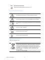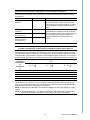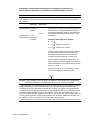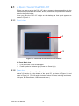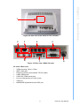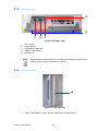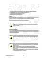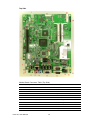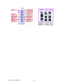
1
User Manual POC-127 Intel® Pineview-M N450 CPU based Point of Care Terminal with 12.1” LED panel The Instructions for the User The document combines text and illustrations, providing a comprehensive overview of the system. The information is presented as sequential steps of action, allowing the user to learn directly how to use the device. The text provides explanations and instructs the user step by- step in the practical use of the product, with short, clear instructions in easy-to-follow sequence. Definitions Warning! A WARNING statement provides important information about a potentially hazardous situation which, if not avoided, could result in death or serious injury. Caution! A CAUTION statement provides important information about a potentially hazardous situation which, if not avoided, may result in minor or moderate injury to the user or patient or in damage to the equipment or other property. Note! A NOTE provides additional information intended to avoid inconveniences during operation. POC-127 User Manual Part No. 2008012700 Edition 1 Printed in Taiwan November 2011 ii Safety Instructions Strictly follow these Instructions for Use, please read these safety instructions carefully. Remind to keep this User's Manual for later reference, and any use of the product requires full understanding and strict observation of all portions of these instructions. Observe all WARNINGS and CAUTIONS as rendered throughout this manual and on labels on the equipment. Repair of the device may also only be carried out by trained service personnel. Advantech recommends that a service contract be obtained with Advantech Service and that all repairs also be carried out by them. Otherwise the correct functioning of the device may be compromised. Warning! Because of the danger of electric shock, never remove the cover of a device while it is in operation or connected to a power outlet. If one of the following situations arises, get the equipment checked by service personnel: a. The power cord or plug is damaged. b. Liquid has penetrated into the equipment. c The equipment has been exposed to moisture. d. The equipment does not work well, or you cannot get it to work according to the user's manual. e. The equipment has been dropped and damaged. f. The equipment has obvious signs of breakage. Disconnect this equipment from any AC outlet before cleaning. Use a damp cloth. Do not use liquid or spray detergents for cleaning and keep this equipment away from humidity. Caution! To avoid short-circuiting and otherwise damaging the device, do not allow fluids to come in contact with the device. If fluids are accidentally spilled on the equipment, remove the affected unit from service as soon as possible and contact the service personnel to verify that patient safety is not compromised. Put this equipment on a reliable surface during installation. Dropping it or letting it fall may cause damage. For plug-in equipment, the power outlet socket must be located near the equipment and must be easily accessible. Caution! To prevent overheating, do not cover the openings and place the device in direct sunlight or near radiant heaters. Make sure the voltage of the power source is correct before connecting the equipment to the power outlet. Position the power cord so that people cannot step on it. Do iii POC-127 User Manual not place anything over the power cord. If the equipment is not used for a long time, disconnect it from the power source to avoid damage by transient over voltage. Caution! Do not leave this equipment in an uncontrolled environment where the storage temperature is below -20° C (-4°F) or above 60° C (140°F). This may damage the equipment. If your computer is losing dramatic time or the BIOS configuration reset to default, the battery has no power. Caution! Do not replace battery yourself. Please contact a qualified technician or your retail. The computer is provided with a battery-powered real-time clock circuit. There is a danger of explosion if battery is incorrectly replaced. Replace only with same or equivalent type recommended by the manufacture. Discard used batteries according to the manufacturer’s instructions. Improper installation of VESA mounting can result in serious personal injury! VESA mount installation should be operated by professional technician, please contact the service technician or your retail if you need this service. The detail operating procedure specified on Appendix A. CLASSIFICATION: Supply Class I adapter No applied part IPX1 Continuous Operation Not AP or APG category Warning! This device is not suitable for use in the presence of flammable anesthetic mixture with air, oxygen, nitrous oxide, or for life support system. Maintenance: to properly maintain and clean the surfaces, use only the approved products or clean with a dry applicator. Caution! When servicing the device, always use replacement parts that are qualified to Advantech standards. Advantech Medical cannot warrant or endorse the safe performance of third-party replacement parts for use with our medical device. Make sure the user not to contact SIP/SOPs and the patient at the same time. When networking with electrical devices, the operator is responsible for ensuring that the resulting system meets the requirements set forth by the following standards: POC-127 User Manual iv ®C EN 60601-1 (IEC 60601-1) Medical electrical equipment Part 1: General requirements for safety ®C EN 60601-1-1 (IEC 60601-1-1) Medical electrical equipment Part 1-1: General requirements for safety Collateral standard: Safety requirements for Medical electrical systems ®C EN 60601-1-2 (IEC 60601-1-2) Medical electrical equipment Part 1-2: General requirements for safety Collateral standard: Electromagnetic compatibility; Requirements and tests Warning! If fix the equipment to mobile equipment, re-evaluation of the product in according to IEC/EN 60601-1 will be required. Accessory equipment connected to the analog and digital interfaces must be in compliance with the respective nationally harmonized IEC standards (i.e. IEC 60950 for data processing equipment, IEC 60065 for video equipment, IEC 61010-1 for laboratory equipment, and IEC 60601-1 for medical equipment.) Furthermore all configurations shall comply with the system standard IEC 60601-1-1. Everybody who connects additional equipment to the signal input part or signal output part configures a medical system, and is therefore, responsible that the system complies with the requirements of the system standard IEC 60601-1-1. The unit is for exclusive interconnection with IEC 60601-1 certified equipment in the patient environment and IEC 60XXX certified equipment outside of the patient environment. If in doubt, consult the technical services department or your local representative. Grounding reliability can only be achieved when the equipment is connected to an equivalent receptacle marked “Hospital Only” or “Hospital Grade”. Use a power cord that matches the voltage of the power outlet, which has been approved and complies with the safety standard of your particular country. v POC-127 User Manual Note! Environmental protection Follow national requirements to dispose of unit. Explanation of Graphical Symbols IEC 60878 and ISO 3864-B.3.6 : Warning: dangerous voltage. ISO 7000-0434 : Caution, consult ACCOMPANYING DOCUMENTS. ISO 7000-1641 : Follow operating instructions or Consult instructions for use. IEC 60417 -5009 : SANDY-BY. IEC 60417-5031 : Direct current. IEC 60417-5021 : Equipotentiality. Disposing of your old product Within the European Union EU-wide legislation, as implemented in each Member State, requires that waste electrical and electronic products carrying the mark (left) must be disposed of separately from normal household waste. This includes monitors and electrical accessories, such as signal cables or power cords. When you need to dispose of your display products, please follow the guidance of your local authority, or ask the shop where you purchased the product, or if applicable, follow any agreements made between yourself. The mark on electrical and electronic products only applies to the current European Union Member States. POC-127 User Manual vi Guidance and manufacturer’s declaration - electromagnetic emissions The model POC-127 is intended for use in the electromagnetic environment specified below. The customer or the user of the model POC-127 should assure that it is used in such an environment. Emissions test Compliance Electromagnetic environment - guidance RF emissions CISPR 11 Group 1 The model POC-127 uses RF energy only for its internal function. Therefore, its RF emissions are very low and are not likely to cause any interference in nearby electronic equipment. RF emissions CISPR 11 Class B Harmonic emissions IEC 61000-3-2 Class A Voltage fluctuations/ flicker emissions IEC 61000-3-3 Not applicable The model POC-127 is suitable for use in all establishments, including domestic establishments and those directly connected to the public low-voltage power supply network that supplies buildings used for domestic purposes. Recommended separation distances between portable and mobile RF communications equipment and the model POC-127 The model POC-127 is intended for use in an electromagnetic environment in which radiated RF disturbances are controlled. The customer or the user of the model POC-127 can help prevent electromagnetic interference by maintaining a minimum distance between portable and mobile RF communications equipment (transmitters) and the model POC-127 as recommended below, according to the maximum output power of the communications equipment. Separation distance according to frequency of transmitter Rated m maximum output power 150 kHz to 80 MHz 80 MHz to 800 MHz 800 MHz to 2,5 GHz of d = 1,2 d = 1,2 d = 2,3 transmitter W 0.01 0.12 0.12 0.23 0.1 0.38 0.38 0.73 1 1.2 1.2 2.3 10 3.8 3.8 7.3 100 12 12 23 For transmitters rated at a maximum output power not listed above, the recommended separation distance d in metres (m) can be estimated using the equation applicable to the frequency of the transmitter, where P is the maximum output power rating of the transmitter in watts (W) according to the transmitter manufacturer. NOTE 1 At 80 MHz and 800 MHz, the separation distance for the higher frequency range applies. NOTE 2 These guidelines may not apply in all situations. Electromagnetic propagation is affected by absorption and reflection from structures, objects and people. vii POC-127 User Manual Information on potential electromagnetic interference and advice on how to avoid or minimize such interference (IEC/EN 60601-1-2:2007) Guidance and manufacturer’s declaration - electromagnetic immunity The model POC-127 is intended for use in the electromagnetic environment specified below. The customer or the user of the model POC-127 should assure that it is used in such an environment. Immunity test IEC 60601 Complitest level ance level Electromagnetic environment - guidance Conducted RF 3 Vrms 3 Vrms IEC 61000-4-6 150 kHz to 80 MHz Portable and mobile RF communications equipment should be used no closer to any part of the model POC-127, including cables, than the recommended separation distance calculated from the equation applicable to the frequency of the transmitter. 3 V/m Radiated RF 3 V/m IEC 61000-4-3 80 MHz to 2,5 GHz Recommended separation distance d = 1,2 d = 1,2 80 MHz to 800 MHz d = 2,3 800 MHz to 2,5 GHz where P is the maximum output power rating of the transmitter in watts (W) according to the transmitter manufacturer and d is the recommended separation distance in metres (m). Field strengths from fixed RF transmitters, as determined by an electromagnetic site survey, a should be less than the compliance level in each frequency range. b Interference may occur in the vicinity of equipment marked with the following symbol: NOTE 1 At 80 MHz and 800 MHz, the higher frequency range applies. NOTE 2 These guidelines may not apply in all situations. Electromagnetic propagation is affected by absorption and reflection from structures, objects and people. a Field strengths from fixed transmitters, such as base stations for radio (cellular/cordless) telephones and land mobile radios, amateur radio, AM and FM radio broadcast and TV broadcast cannot be predicted theoretically with accuracy. To assess the electromagnetic environment due to fixed RF transmitters, an electromagnetic site survey should be considered. If the measured field strength in the location in which the model POC-127 is used exceeds the applicable RF compliance level above, the model POC-127 should be observed to verify normal operation. If abnormal performance is observed, additional measures may be necessary, such as reorienting or relocating the model POC-127. b Over the frequency range 150 kHz to 80 MHz, field strengths should be less than 3 V/m. POC-127 User Manual viii FCC Class B This equipment has been tested and found to comply with the limits for a Class B digital device, pursuant to Part 15 of the FCC Rules. These limits are designed to provide reasonable protection against harmful interference when the equipment is operated in a residential environment. This equipment generates uses and can radiate radio frequency energy. If not installed and used in accordance with this user's manual, it may cause harmful interference to radio communications. Note that even when this equipment is installed and used in accordance with this user's manual, there is still no guarantee that interference will not occur. If this equipment is believed to be causing harmful interference to radio or television reception, this can be determined by turning the equipment on and off. If interference is occurring, the user is encouraged to try to correct the interference by one or more of the following measures: Reorient or relocate the receiving antenna. Increase the separation between the equipment and receiver. Connect the equipment into an outlet on a circuit different from that to which the receiver is connected. Consult the dealer or an experienced radio/TV technician for help. Warning! Any changes or modifications made to the equipment which are not expressly approved by the relevant standards authority could void your authority to operate the equipment. List of Accessories Before installing your Point of Care Terminal, ensure that the following materials have been received: POC-127 series Point of Care Terminal Accessories for POC-127 – CD-ROM disc-"Drivers, User's manual and Utilities" – Mounting kits and packet of screws. – VESA mounting note x1 – China RoHs note x1 Warning! No user serviceable parts inside, refer servicing to qualified personnel. Only the accessories indicated on the list of accessories above have been tested and approved to be used with the device. Accordingly it is strongly recommended that only these accessories be used in conjunction with the specific device. Otherwise the correct functioning of the device may be compromised. ix POC-127 User Manual Additional Information and Assistance Contact your distributor, sales representative, or Advantech's customer service center for technical support if you need additional assistance. Please have the following information ready before you call: Product name and serial number Description of your peripheral attachments Description of your software (operating system, version, application software, etc.) A complete description of the problem The exact wording of any error messages This equipment is a source of electromagnetic waves. Before use please, make sure that there are not EMI sensitive devices in its surrounding which may malfunction therefore. Environmental protection Follow national requirements to dispose of unit. Contact Information Manufacturer Advantech Co., Ltd. No.1, Alley 20, Lane 26, Reuiguang Road Neihu District, Taipei, Taiwan 114, R.O.C. TEL: (02)27927818 Distributed in European by Advantech Europe GmbH Kolberger Strasse 7 D-40599 Dusseldorf, Germany Tel: 49-211-97477350 Fax: 49-211-97477300 Visit the Advantech websites at www.advantech.com or www.advantech.com.tw if you need more information. POC-127 User Manual x Chapter Chapter 1 General Information ............................1 1.1 1.2 Introduction ............................................................................................... 2 Specifications ............................................................................................ 2 Table 1.1: Specifications ............................................................. 2 Figure 1.1 Dimension................................................................... 4 Figure 1.2 VESA Mounting .......................................................... 4 2 System Setup .......................................7 2.1 2.3 2.4 2.5 A Quick Tour of the POC-127 ................................................................... 8 2.1.1 Front view ..................................................................................... 8 Figure 2.1 Front View of the Point of Care Terminal ................... 8 2.1.2 Rear view ...................................................................................... 8 Figure 2.2 Rear view of the Point of Care Terminal..................... 9 Figure 2.3 Rear view of Multi I/O ports ........................................ 9 2.1.3 Bottom view ............................................................................... 10 Figure 2.4 Bottom view .............................................................. 10 2.1.4 Left side view .............................................................................. 10 Figure 2.5 Left side view........................................................... 10 Installation Procedures............................................................................ 11 2.2.1 Connecting the power cord ......................................................... 11 Figure 2.6 Connecting the power cord....................................... 11 2.2.2 Connecting the Ground pin ......................................................... 11 Figure 2.7 POC-127 Equipotential Terminal Pin....................... 12 Figure 2.8 Grounding cable with connector ............................... 12 2.2.3 Switch on the power.................................................................... 12 Figure 2.9 Press the power button to boot system .................... 12 Running the BIOS Setup Program .......................................................... 13 Installing System Software...................................................................... 13 Installing the Drivers................................................................................ 13 3 Chipset ...............................................15 3.1 3.2 3.5 Introduction ............................................................................................. 16 Installation of Intel(R) Rapid Storage Technology Driver ........................ 18 3.2.1 Installation for Windows XP ........................................................ 18 Installation of Chipset Driver ................................................................... 19 3.3.1 Installation for Windows XP ........................................................ 19 Installation of Graphics Driver ................................................................. 22 3.4.1 Intel chipset graphics driver install .............................................. 22 Further information.................................................................................. 25 4 Audio Interface ..................................27 4.1 4.2 4.3 Introduction ............................................................................................. 28 Installation of Audio Driver ..................................................................... 28 4.2.1 Installation for Windows XP ........................................................ 28 Further information.................................................................................. 30 5 PCI Express Ethernet ........................31 5.1 5.2 Introduction ............................................................................................. 32 Installation of Ethernet Driver.................................................................. 32 5.2.1 Installation for Windows XP ........................................................ 32 Further information.................................................................................. 35 2.2 Chapter 3.3 3.4 Chapter Chapter 5.3 xi POC-127 User Manual Chapter 6 Touch Panel....................................... 37 6.1 6.3 Introduction ............................................................................................. 38 6.1.1 SAW Touch Controller ................................................................ 38 6.1.2 Resistive Touch Controller.......................................................... 38 Installation of Touch Screen Driver......................................................... 38 6.2.1 Installation for touch screen driver.............................................. 38 Further information.................................................................................. 44 7 Optional Devices............................... 45 7.1 ................................................................................................................ 46 7.1.1 RFID ........................................................................................... 46 7.1.2 Driver installation ........................................................................ 46 7.1.3 Further information ..................................................................... 48 ................................................................................................................ 48 7.2.1 Smart Card Reader Introduction................................................. 48 7.2.2 Installation of Smart Card Driver................................................. 48 7.2.3 Further information ..................................................................... 49 ................................................................................................................ 50 7.3.1 Wireless Module Introduction ..................................................... 50 7.3.2 Installation of Driver .................................................................... 50 7.3.3 Further information ..................................................................... 51 ................................................................................................................ 52 7.4.1 Advantech SUSI Introduction...................................................... 52 7.4.2 Install Advantech SUSI driver ..................................................... 55 ................................................................................................................ 59 7.5.1 Advantech POC Dashboard Introduction.................................... 59 7.5.2 Install Advantech Dashboard driver........................................... 63 6.2 Chapter 7.2 7.3 7.4 7.5 Chapter 8 Utility and Hot fix .............................. 65 8.1 8.2 Introduction ............................................................................................. 66 Wakeup by external USB device at S3 resume (wakeup) ...................... 66 8.2.1 Installation for Windows XP ........................................................ 66 9 Operation and Safety information ... 67 Appendix A MB Connector Map and Table ......... 69 Appendix B PCM-8708 MB Jumper setting ......... 73 Appendix C POC-127 Cleaning and Disinfecting 77 C.1 Point-of-Care Terminal Cleaning and Disinfecting.................................. 78 Chapter POC-127 User Manual xii Chapter 1 1 General Information 1.1 Introduction The POC-127 is a Intel® AtomTM Processor N450 1.66GHz mobile processor-based computer that is designed to serve as a Point of Care terminal (POC.) It is a PCbased system with 12.1” color TFT LCD display, Single DVI-I Port, Dual on-board 10/ 100/1000 PCI-E Ethernet controller, Quad COM ports, Quad USB 2.0 ports and a 24bit stereo audio controller. With a 2.5” SATA HDD drive optional, the POC-127 is an user-friendly computer. For system integrators, this highly integrated multimedia system lets you easily build a Point of Care (POC) terminal into your applications. The POC-127 makes it an ideal and safe POC solution for patients and hospital practitioners. The POC-127 is specially designed to resist spills and water damage, and ensures dust resistance with its protected LCD, sealed ports, like a complete system. The high contrast ratio (700:1) of POC-127 makes it a perfect image terminal for PACS and DICOM applications. The POC-127 is a reliable solution to your application's processing requirements. The POC-127 is intended to serve as a Point of Care terminal for integration with hospital systems. POC-127 medical computer is designed for general purpose use in hospital environments. POC-127 is for data collection and display for reference - not to be used for life-support systems. The latest version of the user manual is available to be downloaded from http://support.advantech.com.tw/support/ 1.2 Specifications Table 1.1: Specifications Chipset Intel Pineview-M; Intel ICH8M CPU Intel® AtomTM N450 1.66G Hz Processor Front Side Bus 667 MHz Memory Up to 2GB DDR2 667 MHz SDRAM Input rating 18 Vdc, 3.5 A Graphics Controller INTEL Pineview-M with Extreme Graphic technology Expansion Slot Mini PCIe 1 x mini PCIe PCIe /PCI 1 x PCIe x4 slot or PCI x1 (by riser card option) HDD 1 x 2.5” SATA Computing System Storage Identification Ethernet 1x Smart Card Reader (option) Interface 1 x Gigabit Ethernet (isolated) interface (RJ-45) I/O Ports 1 x RS-232 (isolated) and 1 x RS232/422/485 (isolated) serial port; 4 x USB 2.0 ports; 1 x IEEE 1394a ports; 1 x PS/2 mouse and K/B; 1 x VGA port; 1 x Mic-in, 1x headphone (Line)-out, Line-in Speakers 2 x 1 W speakers POC-127 User Manual 2 Chapter 1 Table 1.1: Specifications Display 12.1 inch Display Mode TN, Normally white Max. Resolution 1024 x 768 Max. Colors 262k/16.2M colors Dot size (mm) 0.24 x 0.24 Viewing angle 160/140 Luminance 600 cd/m2 Backlight LED Contrast ratio 700 : 1 DC Model AC adapter Input voltage 1. 100-240Vac, 47-63Hz, 1.62-0.72A 2. 100-240Vac, 47-63Hz, 1.2-0.5A Output voltage 1. 18Vdc, 3.5A (63W) 2. 18Vdc, 5.55A (100W) Battery 3S1P 2100mHA (option) Support over one hours Remark: Trade-off with smart card reader & add on card Power Supply Smart Card reader Supporting ISO/IEC 7816-1, 2, 3 Optional Optional Touch Screen WLAN IEEE 208.11 b/g/n RFID Supports ISO14443A/B and 15693 standard Bluetooth Supports CSR Bluetooth 2.0 + Enhanced Data Rate (EDR) DOM 1-8GB disk on module kit Type Analog Resistive Resolution Continuous Light transmission 75% Controller RS-232 interface (use COM 6) Durability 30 million touches CE,FCC Class B approved Certification Environment Physical Characteristics Platform & utility UL60601-1,EN60601-1 approved Temperature 0 ~ 40°C (32 ~ 104°F) (operating) -20 ~ 60°C (storage) -20 ~ 60°C (transportation) Humidity 10 ~ 95%@40°C (non-condensing) 5 ~ 95% (non condensing) (storage) 5 ~ 95% (transportation) Shock Resistance 20G peak acceleration (11ms duration) Pressure 700-1013 hPa (operation) 375 mmHg to 760 mmHg (storage) 375 mmHg to 760 mmHg (transportation) Water/dust Resistance IPX1 compliant Dimensions (W x H x D) 348 x 287 x 92 mm (13.70" x 11.22" x 3.62") Weight 4.5 kg XP Professional, Windows 7, SUSI 3 POC-127 User Manual General Information Display size Unit: mm 287.36 92.3 348.47 Figure 1.1 Dimension VESA Mounting: 75 x 75 mm Figure 1.2 VESA Mounting POC-127 User Manual 4 Cleaning/Disinfecting During normal use of the POC-127 may become soiled and should, therefore, be cleaned regularly. Agents: Green tinctured soap and Enzymatic detergents Steps: 1. Wipe the POC-127 with a clean cloth that has been moistened in the cleaning solution. 2. Prepare agent per manufacturer’s instructions or hospital protocol. 3. Wipe thoroughly with a clean cloth. Caution! Do not immerse or rinse the POC-127 and its peripherals. If you accidentally spill liquid on the device, disconnect the unit from the power source. Contact your IT support regarding the continued safety of the unit before placing it back in operation. Do not spray cleaning agent on the chassis. Do not use disinfectants that contain phenol. Do not autoclave or clean the POC-127 or its peripherals with strong aromatic, chlorinated, ketone, ether, or Esther solvents, sharp tools or abrasives. Never immerse electrical connectors in water or other liquids. 5 POC-127 User Manual General Information Optional modules Memory: DDR2 667 MHz SDRAM HDD: 2.5" SATA HDD Touchscreen: Analog resistive Chapter 1 Warning! Use suitable mounting apparatus to avoid risk of injury. POC-127 User Manual 6 Chapter 2 System Setup 2 2.1 A Quick Tour of the POC-127 Before you start to set up the POC-127, take a moment to become familiar with the locations and purposes of the controls, drives, connections and ports, which are illustrated in the figures below. When you place the POC-127 upright on the desktop, its front panel appears as shown in Figure 2-1. 2.1.1 Front view 1 2 Figure 2.1 Front View of the Point of Care Terminal 2.1 Front Bezel view 1. LCD panel with Touch Screen option. 2. Power symbol w/ indicator light (Power on: Green light). 2.1.2 Rear view When you turn the Point of Care Terminal around and look at its rear cover, the sunken I/O section is at the bottom of the panel PC, as shown in Figure 2-2 and zoom in Figure 2-3. (The I/O section includes various I/O ports, including serial ports, VGA port, the Ethernet port, USB ports and so on.) POC-127 User Manual 8 Chapter 2 1 System Setup Figure 2.2 Rear view of the Point of Care Terminal 2 3 6 4 5 7 8 Figure 2.3 Rear view of Multi I/O ports 2-2 and 2-3 Rear view 1. VESA mounting 75mm x 75mm 2. IEEE 1394a port 3. Ethernet (network) ports labeled TCP/IP (LAN1) 4. USB1-USB4 ports* 5. COM1 ®C COM2 serial ports 6. Line-out, Microphone-in & Line in jack 7. VGA port 8. KB/MOUSE (keyboard/mouse) PS/2 port 9 POC-127 User Manual 2.1.3 Bottom view 12 13 9 10 11 Figure 2.4 Bottom view 9. 10. 11. 12. 13. DC-in Jack Power switch Equipotential terminal Add-on card bracket Speaker x2 Note! Equipotential terminal need link to hospital ground/earth system before system boot to protect operator and system. 2.1.4 Left side view 14 Figure 2.5 Left side view 14. Smart Card Reader ( option and the smart card for sample only ) POC-127 User Manual 10 2.2.1 Connecting the power cord Figure 2.6 Connecting the power cord 2.2.2 Connecting the Ground pin Step 1.Find the Equipotential Terminal on rear side of POC. An Equipotential Terminal is provided to optionally connect to a hospital ground/earth system Equipment Terminal Figure 2.7 POC-127 Equipotential Terminal Pin 11 POC-127 User Manual System Setup The POC-127 could only be powered by a DC power adapter (SINPRO Model no.MPU63-107 or HPU100-107). Be sure to always handle the power cords by holding the plug ends only. Follow these procedures in order: 1. Connect the female end of the power adapter to the DC jack of the panel PC. (See Figure 2-7.) 2. Connect the female end of the power cord to the DC power adapter. 3. Connect the 3-pin male plug of the power cord to an electrical outlet. Chapter 2 2.2 Installation Procedures Step 2.Prepare the grounding cable and the other terminal links to the hospital ground/earth system. Figure 2.8 Grounding cable with connector Step 3.Grounding cable plug with POC-127 Equipotential Terminal (See Figure 2-8). 2.2.3 Switch on the power Switch on the reset switch on the front cover. (See Figure 2-4.) Figure 2.9 Press the power button to boot system 2.3 Running the BIOS Setup Program Your POC-127 is likely to have been properly set up and configured by your dealer prior to delivery. You may still find it necessary to use the BIOS (Basic Input-Output System) setup program to change system configuration information, such as the current date and time or your type of hard drive. The setup program is stored in readonly memory. It can be accessed either when you turn on or reset the panel PC, by pressing the “Crtl+Alt+Del" key on your keyboard immediately after powering on the computer. The settings you specify with the setup program are recorded in a special area of memory called CMOS RAM. This memory is backed up by a battery so that it will not be erased when you turn off or reset the system. Whenever you turn on the power, the system reads the settings stored in CMOS RAM and compares them to the equipment check conducted during the power on self-test (POST). If an error occurs, POC-127 User Manual 12 2.4 Installing System Software Recent releases of operating systems from major vendors include setup programs which load automatically and guide you through hard disk preparation and operating system installation. The guidelines below will help you determine the steps necessary to install your operating system on the panel PC hard drive. Some distributors and system integrators may have already preinstalled system software prior to shipment of your panel PC. If required, insert your operating system's installation or setup diskette into the external diskette drive until the release button pops out. The BIOS supports system boot-up directly from the CD-ROM drive. You may also insert your system installation CD-ROM disk into your external CD-ROM drive. Power on or reset the system by pressing the "Ctrl"+"Alt"+"Del" keys simultaneously. The Point of Care Terminal will automatically load the operating system from the diskette or CD-ROM. If you are presented with the opening screen of a setup or installation program, follow the instructions on screen. The setup program will guide you through preparation of your hard drive, and installation of the operating system. 2.5 Installing the Drivers After installing your system software, you will be able to set up the Chipset, Graphics, Ethernet, audio and touch screen functions by your own external CD-ROM drive. All the drivers except the CD-ROM drive driver are stored in a CD-ROM disc entitled "Drivers and Utilities." The standard procedures for installing the drivers are described in Chapters 3~8 respectively. The various drivers and utilities in the CD-ROM disc have their own text files which help users install the drivers and understand their functions. These files are a very useful supplement to the information in this manual. For your reference, the directory of drivers on the "Drivers and Utilities" CD-ROM “d:\driver” folder Note! The drivers and utilities used for the POC-127 panel PCs are subject to change without notice. If in doubt, check Advantech's website or contact our application engineers for the latest information regarding drivers and utilities. 13 POC-127 User Manual System Setup Note! Chapter 2 an error message will be displayed on screen, and you will be prompted to run the setup program. POC-127 User Manual 14 Chapter 3 Chipset 3 3.1 Introduction The POC-127 uses the Intel® AtomTM Processor N400 series (code named Pineview-M single-core processor) referred as the processor and Intel® I/O Controller Hub 8 (ICH8) Family Express Chipset referred as the chipset. Processor features: The processor is built on 45-nanometer Hi-K process technology The processor is designed for a two-chip platform as opposed to the traditional three-chip platforms (processor, GMCH, and ICH) On die, primary 32-kB instructions cache and 24-kB write-back data cache Intel® Hyper-Threading Technology (2 threads per core) Single-core processors have on-die 512KB, 8-way L2 cache; dual-core processors have on-die 2 x 512KB, 8-way L2 cache Supports IA 32-bit and Intel 64 architecture Intel® Streaming SIMD Extensions 2 and 3 (SSE2 and SSE3) and Supplemental Streaming SIMD Extensions 3 (SSSE3) support Micro-FCBGA8 packaging technologies Thermal management support via Intel Thermal Monitor 1 (TM1) Thermal Monitor 2 (TM2) Supports C-state of C0/C1(E)/C2(E)/C4(E) Enhanced Intel SpeedStep Technology (EIST) Supports L2 dynamic cache sizing Execute Disable Bit support for enhanced security Memory features: Support DDR2 SDRAMs – Support for DDR2 at data transfer rate of 667 MT/s – One channel of DDR2 memory (consists of 64-bit of data lines): Maximum of two SO-DIMMs in Raw Card-A or Raw Card-C format – I/O Voltage of 1.8 V for DDR2 – Non-ECC, unbuffered DDR2 SO-DIMMs only – 512-Mb, 1-Gb and 2-Gb DDR2 DRAM technologies supported – Maximum of 2-GB memory capacity supported: Maximum of 1-GB memory capacity on one SO-DIMM or Memory Down * Due to standard PC architecture, a certain amount of memory is reserved for system usage and therefore the actual memory size is less than the stated amount. Direct media interface features: Compliant to Direct Media Interface (DMI) Supports 2 lanes in each direction, point-to-point DMI interface to the chipset Raw bit-rate on the data pins of 2.5Gb/s, resulting in a real bandwidth per pair of 250MB/s given the 8b/10b encoding used to transmit data across this interface. Does not account for packet overhead and link maintenance Maximum theoretical bandwidth on interface of 500MB/s in each direction simultaneously, for an aggregate of 1GB/s for the interface 100-MHz reference clock 64-bit downstream address (only 36-bit addressable from the processor) POC-127 User Manual 16 APIC messaging support. Will send Intel-defined “End of Interrupt” broadcast message when initiated by the processor Message Signaled Interrupt (MSI) messages supported Power Management state change messages supported SMI, SCI and SERR error indication Legacy support for ISA regime protocol (PHOLD/PHOLDA) required for parallel port DMA, floppy drive, and LPC bus masters Hybrid AC-DC coupling solution between the processor and the chipset Polarity inversion supported The ICH8 provides extensive I/O support. Functions and capabilities include: PCI Express* Base Specification, Revision 1.1 support PCI Local Bus Specification, Revision 2.3 support for 33 MHz PCI operations (supports up to four Req/Gnt pairs). ACPI Power Management Logic Support Enhanced DMA controller, interrupt controller, and timer functions Integrated Serial ATA host controllers with independent DMA operation on up to three ports (ICH8M only) and AHCI support Integrated IDE controller supports Ultra ATA100/66/33 (Mobile only) USB host interface with support for up to ten USB ports; five UHCI host controllers; two EHCI high-speed USB 2.0 Host controllers Integrated 10/100/1000 GbE MAC with circuit breaker System Management Bus (SMBus) Specification, Version 2.0 with additional support for I2C devices) Supports Intel® High Definition Audio Low Pin Count (LPC) interface Firmware Hub (FWH) interface support Serial Peripheral Interface (SPI) support 17 POC-127 User Manual Chipset Integrated graphics controller feature: The integrated graphics controller contains a refresh of the 3rd generation graphics core Intel® Dynamic Video Memory Technology 4.0 DirectX* 9 compliant Pixel Shader 2.0 200-MHz render clock frequency 2 display ports: LVDS and RGB – Integrated single LVDS channel support resolution up to 1280*800 or 1366*768 – Analog RGB display output up to resolution 1400x1050 @ 60Hz Intel® Clear Video Technology – MPEG2 Hardware Acceleration – ProcAmp Chapter 3 3.2 Installation of Intel (R) Rapid Storage Technology Driver Complete the following steps to install the Chipset driver. Follow the procedures in the flow chart that apply to the operating system that you are using within your POC127. Note! The following windows illustrations are examples only. You must follow the flow chart instructions and pay attention to the instructions which appear on your screen. Note! The CD-ROM drive is designated as °×D°± throughout this chapter. Note! <Enter> means pressing the °×Enter°± key on the keyboard. Note! Before you install the graphic driver of POC-127, please ensure you have installed the “Intel Chipset Software Installation Utility”. You can find this driver in the Utility CD-ROM. Note! The resolution of window display will be fix on 640 x 480 before you install Graphics driver. Depend on your monitor native resolution, the black area might be different. 3.2.1 Installation for Windows XP Because SATA controller default is configured as AHCI mode, you must pre-install the Intel(R) Rapid Storage Technology driver using the F6 installation method described below. Step 1.At the beginning of the operating system installation, press F6 to install a third party SCSI or RAID driver. Step 2.When prompted, select 'S' to Specify Additional Device. Step 3.When prompted, insert the media (floppy, CD/DVD or USB) included Intel Rapid Storage Technology driver and press Enter. Step 4.At this point you should be presented with a selection for ICH8M listed in the picture. Highlight the selection and press Enter. POC-127 User Manual 18 3.3 Installation of Chipset Driver Complete the following steps to install the Chipset driver. Follow the procedures in the flow chart that apply to the operating system that you are using within your POC127. Step 1.Double Click ”infinst_autol.exe” in D:\Driver\XP\Chipset folder. The Install dialog will appear. Step 2.Click Next to continue. Step 3.Read License Agreement and click Yes to proceed. 19 POC-127 User Manual Chipset 3.3.1 Installation for Windows XP Chapter 3 Step 5. Press Enter again to continue. Leave the floppy disk in the system until the next reboot as the software will need to be copied from the floppy disk again when setup is copying files. Step 4.Read file information and click Next to proceed. POC-127 User Manual 20 Chapter 3 Step 5.When the 'Setup COMPLETE' message appears click Finish to restart your computer. Chipset 21 POC-127 User Manual 3.4 Installation of Graphics Driver Complete the following steps to install the graphics driver. Follow the procedures in the flow chart that apply to the operating system that you are using within your POC127. 3.4.1 Intel chipset graphics driver install Step 1.Double Click “winxp.exe” in D:\Driver\XP\VGA folder. Step 2.Driver Information will appear as the picture below, click Next to continue. Step 3.Click Next to continue. POC-127 User Manual 22 Chapter 3 Chipset Step 4.Read License Agreement and click Yes to proceed. Step 5.Read file information and click Next to proceed. 23 POC-127 User Manual Step 6.When the 'Click Next to continue’ message appears click Next to proceed. POC-127 User Manual 24 Chapter 3 Step 7.When the 'Setup Is Complete' message appears click Finish to restart your computer. Chipset 3.5 Further information For further information about the installation in your POC-127, included Driver updates, troubleshooting guides and FAQ lists please visit the following web resources. Intel website: www.intel.com Advantech websites: www.advantech.com www.advantech.com.tw 25 POC-127 User Manual POC-127 User Manual 26 Chapter 4 Audio Interface 4 4.1 Introduction The POC-127's onboard audio interface provides high-quality stereo sound by using the ALC892 audio controller from Realtek. The ALC892 series are high performance 7.1+2 channel High Definition Audio Codecs providing ten DAC channels that simultaneously support 7.1 sound playback, plus 2 channels of independent stereo sound output (multiple streaming) through the front panel stereo outputs. Key Features: All DACs support 44.1K/48K/96K/192KHz sample rate All ADCs support 44.1K/48K/96K sample rate Software selectable boost gain for analog microphone input All analog jacks are stereo Build in headphone amplifiers for headphone jack Supports anti-pop mode when analog power AVDD is on and digital power is off. POC-127 contains one headphone output (Green color) jack, one microphone (Pink color) input jack and one line-in jack. There are two internal speakers to provide stereo audio. 4.2 Installation of Audio Driver Before installing the audio driver, please take note of the procedures detailed below. You must know which operating system you are using in your POC-127, and then refer to the corresponding installation flow chart. Just follow the steps in the flow chart. You can quickly and successfully complete the installation, even though you are not familiar with instructions for Windows. This setup program will install the audio driver and Realtek utility into your system. Note! The following windows illustrations are examples only. You must follow the flow chart instructions and pay attention to the instructions which appear on your screen. Note! The CD-ROM drive is designated as “D” throughout this chapter. Note! <Enter> means pressing the “Enter” key on the keyboard. 4.2.1 Installation for Windows XP Step 1.Double Click “Setup.exe” in D:\Driver\XP\Audio folder. The Install dialog will appear. POC-127 User Manual 28 Chapter 4 Step 2.Click 'Next' to continue. Install program will install driver and utility. It will spend a period of time processing. Audio Interface Step 3.When the 'InstallShield Wizard Complete' message appears click Finish to restart your computer.. 29 POC-127 User Manual 4.3 Further information For further information about the Audio interface installation in your POC-127, included Driver updates, troubleshooting guides and FAQ lists please visit the following web resources. Realtek website: www.realtek.com.tw Advantech websites: www.advantech.com www.advantech.com.tw POC-127 User Manual 30 Chapter 5 5 PCI Express Ethernet 5.1 Introduction The POC-127 is equipped with a high performance PCIe Ethernet chipset Intel 82567V which is fully compliant with IEEE 802.3 10/100/1000 Mbps standards. The Ethernet port provides a standard RJ-45 jack. Product Features (82567V): Reduced power consumption during normal operation and power down modes IEEE 802.3 Ethernet interface for 1000BASE-T,100BASE-TX, and 10BASE-T applications (802.3, 802.3u, and 802.3ab) conformance Supports up to 9 kB jumbo frames (full duplex) Supports carrier extension (half duplex) Auto-negotiation with support for next page Smart speed operation, for automatic speed reduction on faulty cable plants Automatic MDI crossover capable PMA loopback capable (No echo cancel) Advanced power management: – Low power link up – Auto Connect Battery Saver ®C link disconnect Advanced cable diagnostics: – TDR – Channel frequency response Extended configuration load sequence Automatic resolution of FDX/HDX mismatch in 10/100 forced configurations Dual interconnect between MAC and PHY: – LCI for 10/100 Mb/s operation control traffic – GLCI for 1000 Mb/s operation Three LED outputs Multiple voltage regulation modes: – External voltage regulation – Fully integrated linear regulator (nominal 1.05 V, programmable) – Discrete linear voltage regulator (nominal 1.8 V-1.9 V) Supported ICH Integrated MAC Features: – Linksec (ICH10 only) – Manageability: vPro Compatible – Performance: RSS Support Checksum offload 5.2 Installation of Ethernet Driver 5.2.1 Installation for Windows XP Step 1.Double Click “PROWin32.exe” in D:\Driver\XP\LAN folder. POC-127 User Manual 32 Chapter 5 Step 2.Click Next to continue. 33 POC-127 User Manual PCI Express Ethernet Step 3.Read License Agreement and select “accept the terms in the license Agreement” and click Next to proceed. Step 4.When the 'Setup Options' message appears click Next to proceed. Step 5.When the 'Ready to Install the program' message appears click Install to proceed. POC-127 User Manual 34 Step 7.When the 'InstallShield Wizard Complete' message appears click Finish to finish the install program. Chapter 5 Step 6.Several install progress message appear, please wait several minutes to install. PCI Express Ethernet 5.3 Further information For further information about the installation in your POC-127, included Driver updates, troubleshooting guides and FAQ lists please visit the following web resources. Intel website: www.intel.com Advantech websites: www.advantech.com www.advantech.com.tw 35 POC-127 User Manual POC-127 User Manual 36 Chapter 6 Touch Panel 6 6.1 Introduction The POC-127 is supported with a system integrated touch panel. SAW and Resistive touch screen types can be chosen. SAW type was controlled by system COM5, and Resistive Touch Sensor was linked to system COM6. Caution! Please don't install both SAW Touch driver and Resistive Touch driver at same system. Only install one touch driver base on your hardware configuration. 6.1.1 SAW Touch Controller Elo Touch 2701 control board (Elo Part Number D68054-000) 6.1.2 Resistive Touch Controller Build-in Resistive Touch Controller on Mother Board (EETI number: ETP-CP-S5XR) 6.2 Installation of Touch Screen Driver 6.2.1 Installation for touch screen driver Step 1.Double Click “Setup.exe” in D:\Driver\XP\Touch folder. The Install dialog will appear. Step 2.Click Next to continue. POC-127 User Manual 38 Chapter 6 Touch Panel Step 3.Click Next to continue.Because POC-127’s touch controller is controlled by COM6, please do not select the “Install PS/2 interface driver”. 39 POC-127 User Manual Step 4.Click Next to continue. “Install RS232 interface driver” is selected by default. Step 5.Click Next to continue. Please select “None” for “Do 4 point calibration”. The driver install program will do this 4 point calibration when the install completes. POC-127 User Manual 40 Chapter 6 Step 6.Click OK to continue. 41 POC-127 User Manual Touch Panel Step 7.Click Next to continue. Please select “Support Multi-Monitor System”. Step 8.Click Next to continue. If you want to change the driver destination folder, you can click the Browse button to change the folder. Step 9.Click Next to continue. POC-127 User Manual 42 Chapter 6 Step 10.Check “Create an eGalaxTouch Utility shortcut on desktop”. Click Next to continue. Touch Panel Step 11.Click Yes to continue. The install program will search the touchscreen controller, and find it on COM6. Calibrate the panel: Step 12.Click Yes to continue. Please do 4 point calibration to calibrate the touch screen. 43 POC-127 User Manual Step 13.Touch 'X' once at each of the 4 corners on the panel. Please touch each ‘X’ icon at the corners until the icon stops blinking. 6.3 Further information For further information about the installation in your POC-127, included Driver updates, troubleshooting guides and FAQ lists please visit the following web resources. Elo Touch website: www.elotouch.com EETI website: http://www.eeti.com.tw/ Advantech websites: www.advantech.com www.advantech.com.tw POC-127 User Manual 44 Chapter 7 Optional Devices 7 7.1 7.1.1 RFID POC-127 contains ASTAG PMHNFC0003-3 RFID Module. RFID reader helps nurses identify patients and verify themselves as authorized caregivers, as well as reducing prescription errors Feature HF READER SUPPORTS: ISO-14443A, ISO-14443B, ISO-15693, Felic, ISO-18000-3 mode 1, Mifare UltraLight Near Field Communication: NFCIP-1, NFCIP-2, ISO-18092 Compliant, Peer to Peer Communication, Bit rate from 106k up to 848kbps FREQUENCY: 13.56Mhz ± 7KHz Caution! This RFID is a optional function, please don’t install this driver if you didn't install the RFID module. 7.1.2 Driver installation Step 1.Double Click “RFID_NFC_Install.exe” in D:\Driver\XP\RFID folder. The Install dialog will appear. Step 2.Click “Next” to continue. POC-127 User Manual 46 Chapter 7 Step 3.Click “Next” to continue. Optional Devices Step 4.When the complete message appears click 'Finish' to finish the install program. 47 POC-127 User Manual 7.1.3 Further information For further information about the installation in your POC-127, included Driver updates, troubleshooting guides and FAQ lists please visit the following web resources. Advantech websites: www.advantech.com www.advantech.com.tw 7.2 7.2.1 Smart Card Reader Introduction POC-127 contains Smart Card Reader Module. Smart card reader built-in help verify clinicians' identifications Features Supports EMV specification. Supports the Universal Serial Bus Specification, version 2.0, in full speed. Based on ISO7816 implementation. Supports PC Smart Card industry standard ®C PC/SC 1.0. Supports Microsoft Smart Card for Windows. Meets Microsoft WHQL USB Smart Card Reader requirements. Meets US Federal Information Processing Standards (FIPS) Publication 201 requirements on smart card reader interoperability. Includes WDM driver to work on Windows 98 and Windows 2000 Supports CT-API. Supports dual slots for higher security application. Supports T0, T1 protocol, I2C memory card, SLE4418, SLE4428, SLE4432, SLE4442, AT88SC1608 and AT45D041 card. Dedicated hardware block implementation for IC and memory card protocols for highest performance. Implemented as an USB full speed device with bulk transfer endpoint. Built-in 3.3V regulator for single 5V operation Built-in PLL for USB and Smart Card clocks requirements. Supports EEPROM for USB descriptors customization, including VID/PID Available in 48-LQFP Package. Based on USB-CCID class, short APDU level Compatible with Microsoft USB-CCID driver Supports 3V/5V card. 7.2.2 Installation of Smart Card Driver Step 1.Double Click “SmartCardReader_SingleSlot_Driver_Generic_AU9520,9525_1.7.20.13_set up.exe” in D:\Driver\XP\smart card folder. The Install dialog will appear and automatically proceed the installation. Step 2.Select “Finish” to complete the installation. POC-127 User Manual 48 Chapter 7 Optional Devices 7.2.3 Further information For further information about the installation in your POC-127, included Driver updates, troubleshooting guides and FAQ lists please visit the following web resources. Advantech websites: www.advantech.com www.advantech.com.tw 49 POC-127 User Manual 7.3 7.3.1 Wireless Module Introduction PCIE full size Mini-Card wireless module is a highly integrated wireless local area network (WLAN) solution to let users enjoy digital content through the latest wireless technology without using extra cables and cords. It enables a high performance, cost effective, low power, compact solution that easily fits onto one side of a PCIE full size Mini-Card. Compliant with the IEEE 802.11b/g/n standard, module uses Direct Sequence Spread Spectrum (DSSS), Orthogonal Frequency Division Multiplexing (OFDM), BPSK, QPSK, CCK and QAM baseband modulation technologies. A full implementation of the power management functions specified in the IEEE 802.11 standard minimizes system power requirements. Longer Range: Increases wireless range by up to 3 times and reduces dead spots in coverage area. The device adopts Multiple In, Multiple Out” (MIMO) technology with which effectively doubles the data rate. Unlike ordinary wireless networking technologies that are confused by signal reflections, MIMO actually uses these reflections to increase the range and reduce “dead spots” in the wireless coverage area. The robust signal travels farther, maintaining wireless connections up to 3 times farther than standard 802.11g. Faster Speed: WLAN up to 300Mbps data rate. Features: PCIE full size Mini-Card Compliant with IEEE802.11n Draft 6.0 standard Antenna to support 1(Transmit) X 2 (Receive) MIMO technology High speed wireless connection up to 300 Mbps Low power consumption and high performance Enhanced wireless security 7.3.2 Installation of Driver Install Windows Installer Step 1.Double Click “Setup.exe” in D:\Driver\XP\Wireless\Install_CD folder. The Install dialog will appear. Step 2.Click Install be begin the installation. POC-127 User Manual 50 Chapter 7 Optional Devices Step 3. Click Finish to exit the wizard. 7.3.3 Further information For further information about the installation in your POC-127, included Driver updates, troubleshooting guides and FAQ lists please visit the following web resources. Advantech websites: www.advantech.com www.advantech.com.tw 51 POC-127 User Manual 7.4 7.4.1 Advantech SUSI Introduction SUSI - A Bridge to Simplify & Enhance H/W & Application Implementation Efficiency When developers want to write an application that involves hardware access, they have to study the specifications to write the drivers. This is a time-consuming job and requires lots of expertise. Advantech has done all the hard work for our customers with the release of a suite of APIs (Application Programming Interfaces), called the Secured & Unified Smart Interface (SUSI). SUSI provides not only the underlying drivers required but also a rich set of userfriendly, intelligent and integrated interfaces, which speeds development, enhances security and offers add-on value for Advantech platforms. SUSI plays the role of catalyst between developer and solution, and makes Advantech embedded platforms easier and simpler to adopt and operate with customer applications. SUSI Functions Control GPIO General Purpose Input/Output is a flexible parallel interface that allows a variety of custom connections. It supports various Digital I/O devices - input devices like buttons, switches, output devices such as cash drawers, LED lights etc. And, allows users to monitor the level of signal input or set the output status to switch on/off the device. Our API also provides Programmable GPIO which allows developers to dynamically set the GPIO input or output status SMBus SMBus is the System Management Bus defined by Intel Corporation in 1995. It is used in personal computers and servers for low-speed system management communications. Today, SMBus is used in all types of embedded systems. The SMBus API allows a developer to interface a Windows XP or CE PC to a downstream embedded system environment and transfer serial messages using the SMBus protocols, allowing multiple simultaneous device control. POC-127 User Manual 52 I2 C Chapter 7 The I2C API allows a developer to interface a Windows XP or CE PC to a downstream embedded system environment and transfer serial messages using the I2C protocols, allowing multiple simultaneous device control. Monitor Watchdog A watchdog timer (WDT) is a device or electronic card that performs a specific operation after a certain period of time if something goes wrong with an electronic system and the system does not recover on its own. A watchdog timer can be programmed to perform a warm boot (restarting the system) after a certain number of seconds during which a program or computer fails to respond following the most recent mouse click or keyboard action. Hardware Monitor The Hardware Monitor (HWM) API is a system health supervision API that inspects certain condition indexes, such as fan speed, temperature and voltage. 53 POC-127 User Manual Optional Devices I2C is a bi-directional two wire bus that was developed by Phillips for use in their televisions in the 1980s. Today, I2C is used in all types of embedded systems. Hardware Control The Hardware Control API allows developers to set the PWM (Pulse Width Modulation) value to adjust Fan Speed or other devices; can also be used to adjust the LCD brightness. Display Brightness Control The Brightness Control API allows a developer to interface Windows XP and Windows CE PC to easily control brightness. Backlight The Backlight API allows a developer to control the backlight (screen) on/off in Windows XP and Windows CE. POC-127 User Manual 54 Chapter 7 Power Saving CPU Speed Refers to a series of methods for reducing power consumption in computers by lowering the clock frequency. These API allow users to lower the clock from 87.5% down to 12.5%. Benefits Faster Time to Market SUSI's unified API helps developers write applications to control the hardware without knowing the hardware specs of the chipsets and driver architecture. Reduced Project Effort When customers have their own devices connected to the onboard bus, they can either: study the data sheet and write the driver & API from scratch, or they can use SUSI to start the integration with a 50% head start. Developers can reference the sample program on the CD to see and learn more about the software development environment. Enhances Hardware Platform Reliability SUSI provides a trusted custom ready solution which combines chipset and library function support, controlling application development through SUSI enhances reliability and brings peace of mind. Flexible Upgrade Possibilities SUSI supports an easy upgrade solution for customers. Customers just need to install the new version SUSI that supports the new functions. 7.4.2 Install Advantech SUSI driver Step 1.Double Click “Setup.exe” in D:\Driver\XP\SUSI folder. The Install dialog will appear. Step 2.Click Next to continue. 55 POC-127 User Manual Optional Devices Makes use of Intel SpeedStep technology to save power consumption. The system will automatically adjust the CPU Speed depending on the system loading. System Throttling Step 3.Read and accept End-User License Agreement. Click Install to continue. POC-127 User Manual 56 Chapter 7 Step 4.Microsoft .NET Framework 2.0 has been installed, click Finish to continue. Optional Devices Step 5.Click Next to install SUSI. 57 POC-127 User Manual Step 6.Read and accept License Agreement. Click Next to continue. Step 7.Click Install to begin installation. Step 8.Click OK to finish installation and to restart system. POC-127 User Manual 58 7.5.1 Advantech POC Dashboard Introduction 1. Introduction of POC Dashboard This POC Dashboard is a user friendly utility to combine Battery status, Peripheral status, Brightness control, Volume control, Display control and Touch control from one Main Menu. Below is the Dashboard Main Menu, Chapter 7 7.5 Optional Devices Clicking the dash icon on the top right corner will hide the Dashboard to the bot- tom of the Window. Clicking the minimized restore the Dashboard. Clicking the icon in taskbar will icon in the top right corner will close the application. 2. Brightness Control There are 7 levels of display brightness in POC-127. Clicking the icon in “Brightness Control” panel will decrease the brightness in the panel. And the light bar will also show the current brightness level at the same time. 59 POC-127 User Manual Clicking the icon in “Display Control” panel, the Dashboard will turn off the display. Hotkeys “O” and “F” switch display status. 3. Volume Control Clicking the clicking the POC-127 User Manual icon in “Volume Control” panel will decrease the volume and icon will increase it. 60 Chapter 7 Optional Devices 4. Touch Control Clicking the icon in “Touch Control” panel will enable touch functions, and clicking the icon will disable them. (Once touch funtions have been dis- abled, you will need to use the mouse to re-enable them.) 61 POC-127 User Manual 5. Peripheral Status There are five additional devices that POC can install. Blue color text means that the device has been installed and white text means no equipment has been installed. Note: For authorized parts only 6. Battery Status When you click on the Battery button, you may see below message when POC is operating a Battery Pack. “Total Power Remaining” shows the capacity of the battery pack. “Power Source” shows whether “AC” or “Battery” is being used. 7.5.2 Install Advantech Dashboard driver Step 1.Double Click “dotNetFx40_Full_x86_x64.exe” in D:\Driver\XP\Dash board folder. To begin installing Microsoft .NET Framework 4.0. POC-127 User Manual 62 Chapter 7 Step 2.Execute “POC Dashboard.exe”, then showing the dashboard screen. Optional Devices 63 POC-127 User Manual POC-127 User Manual 64 Chapter 8 Utility and Hot fix 8 8.1 Introduction The POC-127 system needs a specific utility or hot fix to support special functions. 8.2 Wakeup by external USB device at S3 resume (wakeup) POC-127 supports three different sleep (suspend) modes, they are: 1. S1: Power On Suspend - system will stop the clock, turn off LCD backlight, but keep all power on. Users can press any key (by mouse or keyboard) to wakeup the system. 2. S3: Suspend to RAM - system will stop the clock and turn off most power rails but RAM will remain powered. It will save all necessary information into memory. In this sleep mode, Windows XP system needs a Hot fix to wakeup the system by USB mouse or keyboard. 3. S4: Suspend to Disk (Hibernation) - system will stop the clock and turn off most power, including RAM memory power, and it will save all necessary information into the Hard Disk. In this sleep mode, users need to press and hold the power button to wakeup the system. 8.2.1 Installation for Windows XP Step 1.Double click the “USBRG.REG” in D:\Driver\XP\USB folder Step 2. Click Yes to install this registry information. Step 3.Click OK to close the successfully installed information window. POC-127 User Manual 66 Chapter 9 9 Operation and Safety information General Safety Guide For your own safety and that of your equipment, always take the following precautions. Disconnect the power plug (by pulling the plug, not the cord), from your computer if any of the following conditions exists: * The power cord or plug becomes frayed or otherwise damaged * You spill something into the case * Your computer has been dropped or the case has been otherwise damaged * You suspect that your computer needs service or repair * You want to clean the computer or screen * You want to remove/install any parts Thermal The rear metal VESA mount holes of the POC-127 case functions as a cooling air flow inlet. And POC-127 case side vent hole as a cooling air flow outlet. These air inlet and outlet transfer heat from inside the computer to the cooler air outside. Do not block these hole/vent by any soft material. Warning! Do not place your POC-127 system on a pillow or other soft material when it is on, as the material may block the airflow and cause the computer to overheat. Disconnect the power The only way to disconnect power completely is to unplug the power cord. Make sure at least one end of the power cord is within easy reach so that you can unplug the computer when you need to. Warning! Your AC cord came equipped with a three-wire grounding plug (a plug that has a third grounding pin). This plug will fit only a grounded AC outlet. If you are unable to insert the plug into an outlet because the outlet is not grounded, contact a licensed electrician to replace the outlet with a properly grounded outlet. Do not defeat the purpose of the grounding plug. Warning! Never push objects of any kind into this product through the openings in the case. Doing so may be dangerous and result in fire or a dangerous electric shock. Never place anything on system case before turn off computer. Never turn on your computer unless all of its internal and external parts are in place. Operating the computer when it is open or missing parts can be dangerous and can damage your computer. POC-127 User Manual 68 Appendix A A MB Connector Map and Table Top Side Mother Board Connector Table (Top Side) No. Description No. Description 1 DC-IN Connector 24 P/S2 2 Battery Connector 25 COM 3 3 PCIEx16 Slot 26 COM 4 4 Bluetooth Connector 27 System Reset Jumper 5 RFID Connector 28 EC Reset Button 6 Smart Card Reader Connector 29 COM1 RS232/422/485 Jumper 7 Disk On Module(DOM) Connector 30 SATA1 Signal Connector 8 Internal Power Button 31 SATA0 Signal Connector 9 Speaker Connector 32 SATA1 Power Connector 10 Power Button 33 SATA0 Power Connector 11 Power LED Connector 34 Keyboard Matrix Connector POC-127 User Manual 70 Headphone Out 35 CF Card 13 Mic. In 36 Clear CMOS Jumper 14 Line In 37 DDR3 Socket B 15 CRT 38 DDR3 Socket A 16 1394a 39 Touch Screen Connector 17 LAN 40 MINI-PCIE Connector 18 USB(Port3) 41 LVDS Connector 19 USB(Port2) 20 USB(Port1) 21 USB(Port0) 22 COM 1 23 COM 2 Mother Board Connector Table (Bottom Side) MB Connector Table (Top Side) No. DescriptionNo.Description 44 RTC Battery Connector No. Description 44 RTC Battery Connector No. Description 71 POC-127 User Manual Appendix A MB Connector Map and Table 12 POC-127 User Manual 72 Appendix B B PCM-8708 MB Jumper setting Jumper Setting: CN10 Clear CMOS CN45 System Reset CN26 COM1 (RS232/422/485) Select CN10 Clear CMOS Description Clear CMOS Setup Setting Function (1-2) Clear CMOS Setup (No Connect) Normal Operation (Default) POC-127 User Manual 74 System Reset Description System Reset Switch Setting Function (1-2) System Reset (No Connect) Normal Operation (Default) MB CN7 LVDS Power Select Description LVDS Power 3.3V/5V Select Setting Function (1-2) 5 V (Default) (2-3) 3.3 V CN26 COM1 RS232/422/485 output type setting Description COM1 RS232/422/485 output type setting Setting Function (5-6), (7-9), (8-10), (13-15), (14-16) RS232 (Default) (3-4), (9-11) (10-12), (15-17) (16-18) RS422 (1-2), (9-11) (10-12), (15-17) (16-18) RS485 75 Appendix B PCM-8708 MB Jumper setting CN45 POC-127 User Manual POC-127 User Manual 76 Appendix C C POC-127 Cleaning and Disinfecting C.1 Point-of-Care Terminal Cleaning and Disinfecting During normal use of the POC (Point-of-Care Terminal) the device may become dirty and should be regularly cleaned. Steps: 1. Prepare cleaning agent per manufacturer’s instructions or hospital protocol. 2. Wipe the POC with a clean cloth that has been moistened in the cleaning solution. 3. Wipe thoroughly with a clean cloth. Cleaning agent list: chemical disinfectants which have been tested on the POC. No. Cleaning Agents 1 Cidex 2 Isopropyl alcohol 3 Green tinctured soap 4 Windex 5 Alcohol 6 Alcohol 70% 7 Chloride 1000 PPM Caution! XXX-XXXX User Manual Do not immerse or rinse the POC or its peripherals. If you accidentally spill liquid on the device, disconnect the unit from the power source. Contact your IT support department regarding the continued safety of the unit before placing it back in operation-Do not spray cleaning agent on the chassis. Do not use disinfectants that contain phenol. Do not autoclave or clean the POC or its peripherals with strong aromatic, chlorinated, ketone, either, or ether solvents, sharp tools or abrasives. Never immerse electrical connectors in water or other liquids. 78 Appendix C POC-127 Cleaning and Disinfecting XXX-XXXX User Manual 79 www.advantech.com Please verify specifications before quoting. This guide is intended for reference purposes only. All product specifications are subject to change without notice. No part of this publication may be reproduced in any form or by any means, electronic, photocopying, recording or otherwise, without prior written permission of the publisher. All brand and product names are trademarks or registered trademarks of their respective companies. © Advantech Co., Ltd. 2011