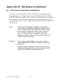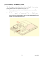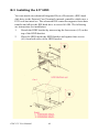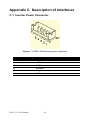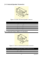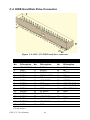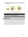
1
POC-125
Pentium® M processor-based
Point of Care Terminal with 12.1"
TFT LCD
User Manual
Copyright
This document is copyrighted 2006, by Advantech Co., Ltd. All rights are
reserved. Advantech Co., Ltd. reserves the right to alter the products
described in this manual at any time without notice.
No part of this manual may be reproduced, copied, translated or transmitted in any form or by any means without the prior written permission of
Advantech. Information provided in this manual is intended to be accurate and reliable. However, Advantech assumes no responsibility for use
of this manual, nor for any infringements upon the rights of third parties
which may result from such use.
Acknowledgements
All brand and product names mentioned herein are trademarks or registered trademarks of their respective holders.
Part No. 2006012500
1st Edition
Printed in Taiwan
POC-125 User Manual
Mar 2006
ii
Declaration of Conformity
FCC Class B
This equipment has been tested and found to comply with the limits for a
Class B digital device, pursuant to Part 15 of the FCC Rules.
These limits are designed to provide reasonable protection against harmful interference when the equipment is operated in a residential environment. This equipment generates, uses and can radiate radio frequency
energy. If not installed and used in accordance with this user manual, it
may cause harmful interference to radio communications.
Note that even when this equipment is installed and used in accordance
with this user manual, there is still no guarantee that interference will not
occur. If this equipment is believed to be causing harmful interference to
radio or television reception, this can be determined by turning the equipment on and off. If interference is occurring, the user is encouraged to try
to correct the interference by one or more of the following measures:
•
Reorient or relocate the receiving antenna
•
Increase the separation between the equipment and the receiver
•
Connect the equipment to a power outlet on a circuit different from
that to which the receiver is connected
•
Consult the dealer or an experienced radio/TV technician for help
Warning
Any changes or modifications made to the equipment which are not expressly approved by the
relevant standards authority could void your
authority to operate the equipment.
Caution
Danger of explosion if battery is incorrectly
replaced. Replace only with the same or equivalent type recommended by the manufacturer.
Dispose of used batteries according to the manufacturer's instructions.
iii
Packing List
Before installing your Point of Care Terminal, ensure that the following
materials have been received:
•
POC-125 series Point of Care Terminal
•
User manual
•
Accessories for POC-125
-
Y-shaped adapter for PS/2 mouse and keyboard
-
Power cord (1.8 m) - USA type (other types are available on
request)
-
Drivers and Utilities CD-ROM disc
-
Mounting kits and packet of screws
Warning
To prevent electric shock, do not remove cover.
No user serviceable parts inside, refer servicing
to qualified personnel.
Technical Support and Assistance
1.
Visit the Advantech websites at www.advantech.com or
www.advantech.com.tw where you can find the latest information
about the product.
2.
Contact your distributor, sales representative, or Advantech's customer service center for technical support if you need additional
assistance. Please have the following information ready before you
call:
• Product name and serial number
•
Description of your peripheral attachments
•
Description of your software (operating system, version, application software, etc.)
•
A complete description of the problem
•
The exact wording of any error messages
•
This equipment is a source of electromagnetic waves. Before
use please, make sure that there are no EMI sensitive devices in
nearby which may malfunction because of these electromagnetic waves.
POC-125 User Manual
iv
Note
1 Use only the following approved power adapters:
•
SINPRO Model no.MPU50-108
(Input voltage rated 100 ~ 240 VAC, 47 ~
63 Hz, 1.35 A max; output voltage rated 24
VDC, 2.08 A)
•
XPiQ Model no.PCM80PS24
(Input voltage rated 100 ~ 240 VAC, 47 ~
63 Hz, 1.1 ~ 0.45 A; output voltage rated
24 VDC, 3.33 A max)
2 Use a 3 V @ 195 mA lithium battery (Model
No. BR2032)
3 Carry the unit with both hands, handle with
care
4 Our European representative is:
Advantech Europe GmbH
Kolberger Straße 7
D-40599 Düsseldorf, Germany
Tel: 49-211-97477350
Fax: 49-211-97477300
5 To properly maintain and clean the surfaces,
use only approved products or clean with a
dry applicator
v
Safety Instructions
1.
Read these safety instructions carefully.
2.
Keep this User Manual for later reference.
3.
Disconnect this equipment from any AC outlet before cleaning.
Use a damp cloth. Do not use liquid or spray detergents for cleaning.
4.
For plug-in equipment, the power outlet socket must be located
near the equipment and must be easily accessible.
5.
Keep this equipment away from humidity.
6.
Put this equipment on a reliable surface during installation. Dropping it or letting it fall may cause damage.
7.
The openings on the enclosure are for air convection. Protect the
equipment from overheating. DO NOT COVER THE OPENINGS.
8.
Make sure the voltage of the power source is correct before connecting the equipment to the power outlet.
9.
Position the power cord so that people cannot step on it. Do not
place anything over the power cord.
10.
All cautions and warnings on the equipment should be noted.
11.
If the equipment is not used for a long time, disconnect it from the
power source to avoid damage by transient overvoltage.
12.
Never pour any liquid into an opening. This may cause fire or electrical shock.
13.
Never open the equipment. For safety reasons, the equipment
should be opened only by qualified service personnel.
14.
If one of the following situations arises, get the equipment checked
by service personnel:
a. The power cord or plug is damaged.
b. Liquid has penetrated into the equipment.
c. The equipment has been exposed to moisture.
d. The equipment does not work well, or you cannot get it to work
according to the user manual.
e. The equipment has been dropped and damaged.
f. The equipment has obvious signs of breakage.
15.
DO NOT LEAVE THIS EQUIPMENT IN AN UNCONTROLLED
ENVIRONMENT WHERE THE STORAGE TEMPERATURE IS
POC-125 User Manual
vi
BELOW -20° C (-4° F) OR ABOVE 60° C (140° F). THIS MAY
DAMAGE THE EQUIPMENT.
16.
If your computer’s clock is losing time, or the BIOS configuration
has reset to defaults, the battery has no power.
Caution
1 Do not replace the battery yourself. Please
contact a qualified technician or your supplier.
2 The computer is provided with a battery-powered real-time clock circuit. There is a danger
of explosion if battery is incorrectly replaced.
Replace only with same or equivalent type
recommended by the manufacturer. Discard
used batteries according to the manufacturer's instructions.
17.
IMPROPER INSTALLATION OF THE VESA MOUNTING KIT
CAN RESULT IN SERIOUS PERSONAL INJURY! The VESA
mounting kit should be installed by a professional technician.
Please contact a service technician or your supplier if you need this
service.
18.
CLASSIFICATION:
• Class I Equipment
•
No applied part
•
IPX1
•
Continuous Operation
•
Not AP or APG category
19.
Disconnect device at the appliance inlet.
20.
Follow national regulations when disposing of the unit.
21.
To properly maintain and clean the surfaces, use only the approved
products or clean with a dry applicator.
22.
Contact information:
No.1, Alley 20, Lane 26, Reuiguang Road
Neihu District, Taipei,
Taiwan 114, R.O.C.
TEL: (02)27927818
vii
23.
This equipment shall not be used in life support systems.
24.
This equipment shall be connected only to IEC 60601-1 approved
equipment.
25.
The sound pressure level at the operator's position according to IEC
704-1:1982 is no more than 70dB(A).
DISCLAIMER
POC-125 User Manual
This set of instructions is given according to IEC
704-1. Advantech disclaims all responsibility for
the accuracy of any statements contained herein
viii
Contents
Chapter
1 General Information ....................................... 2
1.1
1.2
1.3
1.4
Chapter
2 Chapter 2 System Setup................................ 10
2.1
2.2
2.3
2.4
2.5
Chapter
Chapter
2.2.1
2.2.2
2.2.3
2.2.4
2.2.5
Connecting the power cord ........................................... 11
Connecting the keyboard and mouse ............................ 13
Switching on the power................................................. 14
Connecting the COM ports (COM 1, 2)........................ 14
Install the ground safety cable....................................... 14
Running the BIOS Setup Program .................................. 15
Installing System Software.............................................. 15
Installing the Drivers....................................................... 16
3 PCI Bus Ethernet Interface.......................... 18
Introduction ..................................................................... 18
Installation of Ethernet Driver......................................... 18
3.3
Further information ......................................................... 20
3.2.1
Installation for Windows 2000/XP................................ 18
4 PCI Graphic Setup........................................ 22
4.2
4.3
Chapter
A Quick Tour of the POC-125 ........................................ 10
Installation Procedures .................................................... 11
3.1
3.2
4.1
Chapter
Introduction ....................................................................... 2
General Specifications....................................................... 2
Cleaning/Disinfecting........................................................ 6
Dimensions........................................................................ 7
Introduction ..................................................................... 22
4.1.1
4.1.2
4.1.3
Chipset........................................................................... 22
Display memory ............................................................ 22
Display types ................................................................. 22
Installation of PCI Graphic Driver .................................. 22
4.2.1
Installation for Windows 2000/XP................................ 23
Further information ......................................................... 24
5 Audio Interface.............................................. 26
5.1
5.2
Introduction ..................................................................... 26
Installation of Audio Driver ............................................ 26
5.3
Further information ......................................................... 27
5.2.1
Installation for Windows 2000/XP............................... 27
6 Touchscreen Interface .................................. 30
6.1
6.2
6.3
Introduction ..................................................................... 30
6.1.1
6.1.2
6.1.3
General Information ...................................................... 30
General specifications ................................................... 30
Environmental specifications ........................................ 30
Installation of Driver for Touchscreen ............................ 31
6.2.1
6.2.2
Installation for Windows 2000...................................... 32
Installation for Windows XP......................................... 33
Further Information ......................................................... 33
ix
Table of Contents
Appendix A VESA Mounting ............................................ 36
A.1
Install VESA Mounting................................................... 36
Appendix B Hardware Installation................................... 38
B.1
B.2
B.3
Overview of Hardware Installation ................................. 38
Installing the Battery Pack .............................................. 39
Installing the 2.5" HDD................................................... 40
Appendix C Description of Interfaces............................... 44
C.1
C.2
C.3
C.4
C.5
C.6
C.7
C.8
C.9
Inverter Power Connector .............................................. 44
Internal Speaker Connector ............................................ 45
Internal Power Button Connector.................................... 45
EIDE Hard Disk Drive Connector .................................. 46
CD-ROM Connector (*Reserved)................................... 47
CPU Fan Power Connector (*Reserved)......................... 47
PCI Bus Expansion Connector (PCI1) ............................ 48
Touchscreen Connector................................................... 48
COM2.............................................................................. 49
Appendix D Jumper Settings and Connectors ................. 52
D.1
D.2
D.3
D.4
Jumpers and connectors .................................................. 52
D.1.1
D.1.2
D.1.3
D.1.4
D.1.5
Setting jumpers.............................................................. 52
Jumpers and switches .................................................... 53
Locating jumpers........................................................... 53
Connectors..................................................................... 54
Locating connectors ...................................................... 54
CMOS Clear for External RTC (S2) ............................... 55
COM port Interface Configuration (JP1) ........................ 55
D.3.1 COM1/COM2/COM3 Pin9 Output Type Setting (JP2/
JP4/JP3) ......................................................................... 57
VGA Interface ................................................................. 57
D.4.1 VGA information .......................................................... 58
POC-125 User Manual
x
CHAPTER
1
2
General Information
This chapter gives background information of the POC-125.
Sections include:
•
Introduction
•
General Specifications
•
Cleaning/Disinfecting
•
Dimensions
Chapter 1 General Information
1.1 Introduction
The POC-125 is a multimedia Pentium® Mobility processor-based computer that is designed to serve as a Point of Care terminal (POC). It is a
PC-based system with 12.1" color TFT LCD display, on-board PCI Ethernet controller, dual COM port interfaces and a 16-bit stereo audio controller. With a built-in 2.5" HDD drive, and CF card sockets, the POC-125 is
as quiet and user-friendly as a notebook computer. For system integrators,
this silent, compact, mobile, and highly integrated multimedia system lets
you easily build a Point of Care Terminal into your applications. Common industrial applications include factory automation systems, precision
machinery, and production process control. It is also suitable for many
non-industrial applications, including interactive kiosk systems, entertainment management, and car park automation. The POC-125 is a reliable solution to your application's processing requirements.
1.2 General Specifications
General
•
Dimensions (W x H x D): 348 x 257 x 92 mm (13.70" x 10.12" x
3.62 ")
•
Weight: 4.54 kg (10 lb)
•
Power supply: DC model: 50 watts max
External DC Adapter (Manufacturer: SINPRO; Model no. MPU50108) used within POC-125XXXXXXXX
-
Input voltage: 100 ~ 240 VAC, 47 ~ 63 Hz, 1.35 A max
-
Output voltage: +24 VDC, 2.08 A max
External DC Adapter (Manufacturer:XPiQ; Model no.
PCM80PS24) used within POC-125XXXXXXXX
-
Input voltage: 100 ~ 240 VAC, 47 ~ 63 Hz, 1.1 ~ 0.45 A
-
Output voltage: +24 VDC, 3.33 A max
•
Disk drive housing: Space for one 2.5" HDD
•
Front panel: IP65/NEMA compliant
•
Whole System: IPX1 compliant
POC-125 User Manual
2
Standard PC functions
•
CPU: Intel® Pentium® M or Celeron® M processor
•
Memory: DDR200/266/333 SDRAM, 184-pin DIMM socket x 2,
Max. to 2 GB capacity
•
System chipset: Intel 855GME GMCH/ ICH4 Chipset 400 MHz
PSB
•
BIOS: Award 256 KB Flash BIOS, supports Plug & Play, APM
•
Serial ports: Two RS-232 ports with optical isolation. All ports are
compatible with 16C550 UARTs
•
Universal serial bus (USB) port: Supports up to four USB ports
•
IEEE1394a port:1 IEEE1394a port
•
Watchdog timer: 62-level, interval 1 ~ 62 seconds. Automatically
generates system reset when the system stops due to a program
error or EMI.
•
CMOS Battery (BIOS): 3.0 V @ 195 mA lithium battery
Flat panel interface
•
Chipset: Intel 855GME
•
Memory Size: Optimized shared memory architecture, supports 1
or 8 MB frame buffer using system memory
•
Display type: Simultaneously supports CRT and flat panel displays
(EL, LCD and gas plasma)
•
Display resolution: Supports non-interlaced CRT and TFT LCD
displays up to 1280 x 1024 @ 16 M colors
Audio function
•
Chipset: Realtek ALC202
•
Audio controller: 16-bit codec, Full-Duplex stereo single-chip PCI
audio solution
•
Speaker: Full alarm volume > 70 dB(A) 1 meter
•
Stereo sound: 100% DOS game compatible (Sound Blaster or
Sound Blaster Pro)
•
Audio interface: Microphone-in, Line-in, Line-out and Game
ports (MPU-401)
3
Chapter 1
PCI bus Ethernet interface
•
Ethernet interface: Full compliance with IEEE 802.3u 100Base-T
and 10 Base-T specifications. Includes software drivers and boot
ROM
•
100/10Base-T auto-sensing capability
Touchscreen (optional)
Type
Resolution
Light Transmission
Controller
Power Consumption
Software Driver
Durability
(touches in a lifetime)
Note
Analog Resistive
Continuous
75%
RS-232 interface (uses COM4)
+5 V @ 200 mA
Supports Windows 2000, Windows XP
30 million
The Point of Care Terminal with the optionally
installed touchscreen will share COM4. Once the
touchscreen is installed, COM4 cannot be used
for other purposes.
Optional modules
•
Memory: 128/256/512 MB DDR200/266/333 DRAM
•
HDD: 2.5" HDD
•
Touchscreen: Analog resistive
POC-125 User Manual
4
Environment
•
Temperature: 0 ~ 40° C (32 ~ 104° F)
•
Relative humidity: 10 ~ 40° C / 20% ~ 90% RH operating -20 ~
50° C / 10% ~ 95% RH Storage (Non-condensing)
•
Shock: 30 G, half sine, 11 msec duration
•
Random Vibration: 0.002 G²/Hz (1Grms) (5 ~ 500 Hz)
•
Power MTBF: 100,000 hours
•
Altitudes: 6,000 feet (Operational); 40,000 feet (shipping)
•
Certifications:
-
EMC: CE, FCC approved
-
Safety: UL60601-1 and EN60601-1 approved.
-
This device bears the CE label in accordance with the provisions of the EMC Directive 89/336/EMC.
LCD Specifications
•
Display type: 12.1" TFT LCD
•
Resolution: 800 x 600
•
Colors: 262,144 (6 bits/color)
•
Dot size (mm): 0.307 x 0.307
•
Viewing angle (H/V): 140°/110°
•
Luminance: 400 cd/m2
•
Contrast ratio: 500 : 1
•
LCD MTBF: 50,000 hours
•
Backlight lifetime: 50,000 hours
5
Chapter 1
1.3 Cleaning/Disinfecting
During normal use, the POC-125 may become soiled and should, therefore, be cleaned regularly. Agents: Green tinctured soap and Enzymatic
detergents.
Steps:
1.
Wipe the POC-125 with a clean cloth that has been moistened in
the cleaning solution.
2.
Prepare the cleaning agent according to the manufacturer's instructions or hospital protocol.
3.
Wipe thoroughly with a clean cloth.
Cautions
Do not immerse or rinse the POC-125 and its
peripherals. If you accidentally spill liquid on the
device, disconnect the unit from the power
source. Contact your Biomed regarding the continued safety of the unit before placing it back in
operation.
Do not spray cleaning agent on the chassis.
Do not use disinfectants that contain phenol.
Do not autoclave or clean the POC-125 or its
peripherals with strong aromatic, chlorinated,
ketone, ether, or Esther solvents, sharp tools or
abrasives.
Never immerse electrical connectors in water or
other liquids.
POC-125 User Manual
6
1.4 Dimensions
Figure 1.1: Dimensions of the POC-125
7
Chapter 1
POC-125 User Manual
8
CHAPTER
2
2
System Setup
This chapter provides brief instructions
for operating the POC-125.
Sections include:
•
A Quick Tour of the POC-125
•
Installation Procedures
•
Running the BIOS Setup Program
•
Installing System Software
•
Installing the Drivers
Chapter 2 Chapter 2 System Setup
2.1 A Quick Tour of the POC-125
Before you start to set up the POC-125, take a moment to become familiar with the locations and purposes of the controls, drives, connections
and ports, which are illustrated in the figures below.
When you place the POC-125 upright on the desktop, its front panel
appears as shown in Figure 2-1.
Figure 2.1: Front View of the Point of Care Terminal
When you turn the Point of Care Terminal around and look at its rear
cover, the sunken I/O section is at the rear of the panel PC, as shown in
Figure 2-2. The I/O section includes various I/O ports, including serial
ports, VGA port, the Ethernet port, USB ports, the microphone jack, and
so on.
POC-125 User Manual
10
Figure 2.2: Rear view of the Point of Care Terminal
2.2 Installation Procedures
2.2.1 Connecting the power cord
The POC-125 can only be powered by a DC power adapter (SINPRO
Model no.MPU50-108). Be sure to always handle the power cords by
holding the plug ends only.
Follow these procedures:
1.
Connect the female end of the power adapter to the DC jack of the
panel PC. (See Figure 2-3.)
2.
Connect the female end of the power cord to the DC power adapter.
11
Chapter 2
3.
Connect the 3-pin male plug of the power cord to an electrical outlet.
Figure 2.3: Connecting the power cord
POC-125 User Manual
12
2.2.2 Connecting the keyboard and mouse
1.
Connect the Y-shaped adapter to the PS/2 mouse and keyboard port
on the I/O section of the POC-125. (See Figure 2-4.)
2.
Connect the PS/2 mouse and keyboard to the Y-shaped adapter.
(See Figure 2-4.)
Figure 2.4: Connecting the mouse and keyboard
13
Chapter 2
2.2.3 Switching on the power
Switch on the power switch on the rear cover. (See Figure 2-5.)
2.2.4 Connecting the COM ports (COM 1, 2)
Figure 2.5: COM port and power switch location
2.2.5 Install the ground safety cable
The POC-125 provides an Earth Ground connector (See Figure 2-2). This
connector provides earth ground to the unit if the AC power receptacle
you are plugging into does not contain a ground prong.
POC-125 User Manual
14
2.3 Running the BIOS Setup Program
Your POC-125 is likely to have been properly set up and configured by
your dealer prior to delivery. You may still find it necessary to use the
BIOS (Basic Input-Output System) setup program to change system configuration information, such as the current date and time or your type of
hard drive. The setup program is stored in read-only memory. It can be
accessed either when you turn on or reset the panel PC, by pressing the
Crtl+Alt+Del keys immediately after powering on the computer.
The settings you specify with the setup program are recorded in a special
area of memory called CMOS RAM. This memory is backed up by a battery so that it will not be erased when you turn off or reset the system.
Whenever you turn on the power, the system reads the settings stored in
CMOS RAM and compares them to the equipment check conducted during the power on self-test (POST). If an error occurs, an error message
will be displayed on screen, and you will be prompted to run the setup
program.
2.4 Installing System Software
Recent releases of operating systems from major vendors include setup
programs which load automatically and guide you through hard disk
preparation and operating system installation. The guidelines below will
help you determine the steps necessary to install your operating system
on the panel PC hard drive.
Note
Some distributors and system integrators may
have already pre-installed system software prior
to shipment of your panel PC.
If required, insert your operating system's installation or setup diskette
into the external diskette drive until the release button pops out.
The BIOS supports system boot-up directly from the CD-ROM drive.
You may also insert your system installation CD-ROM disk into your
external CD-ROM drive.
Power on or reset the system by pressing the Ctrl+Alt+Del keys simultaneously. The Point of Care Terminal will automatically load the operating
system from the diskette or CD-ROM.
15
Chapter 2
If you are presented with the opening screen of a setup or installation program, follow the instructions on screen. The setup program will guide
you through preparation of your hard drive, and installation of the operating system.
2.5 Installing the Drivers
After installing your system software, you will be able to set up the Ethernet, VGA, audio and touchscreen functions by your own external CDROM drive. All the drivers except the CD-ROM drive driver are stored in
a CD-ROM disc entitled “Drivers and Utilities.”
The standard procedures for installing the Ethernet, VGA, audio, and
touchscreen drivers are described in Chapters 3, 4, 5, and 6 respectively.
The utility directory includes multimedia programs. Refer to the
README.TXT file inside the VGA folders for more detailed information. The various drivers and utilities in the CD-ROM disc have their own
text files which help users install the drivers and understand their functions. These files are a very useful supplement to the information in this
manual. For your reference, the directory of drivers on the “Drivers and
Utilities” CD-ROM is:
D:
Audio (drivers)
Chipset (software)
Document (manuals)
Elotouch (drivers)
LAN (Ethernet drivers)
USB 2.0 (drivers)
VGA (drivers)
Figure 2.6: The file directory on “Drivers and Utilities” CD-ROM
Note
The drivers and utilities used for the POC-125
panel PCs are subject to change without notice.
If in doubt, check Advantech's website or contact
our application engineers for the latest information regarding drivers and utilities.
POC-125 User Manual
16
CHAPTER
3
2
PCI Bus
Ethernet Interface
This chapter provides brief instructions
about configuring the Ethernet interface of the POC-125.
Sections include:
•
Introduction
•
Installation of Ethernet Driver
•
Further information
Chapter 3 PCI Bus Ethernet Interface
3.1 Introduction
The POC-125 is equipped with a high-performance 32-bit
Ethernet chipset which is fully compliant with IEEE 802.3
100 Mbps CSMA/CD standards. It is supported by major network operating systems. It is also both 100Base-T and
10Base-T compatible.
3.2 Installation of Ethernet Driver
3.2.1 Installation for Windows 2000/XP
Complete the following steps to install the LAN driver. Follow the procedures in the flow chart that apply to the operating system that you are using within your POC-125.
Important
The following Windows illustrations are examples
only. You must follow the flow chart instructions
and pay attention to the instructions which
appear on your screen.
Note
The external CD-ROM drive is designated as “D”
throughout this chapter.
<Enter> means pressing the “Enter” key on the
keyboard.
POC-125 User Manual
18
19
Chapter 3
3.3 Further information
For further information about the Ethernet installation in your POC-125,
included Driver updates, troubleshooting guides and FAQ lists please
visit the following web resources.
Realtek website:
www.intel.com.tw
Advantech websites:
www.advantech.com
www.advantech.com.tw
POC-125 User Manual
20
CHAPTER
4
2
PCI Graphic Setup
This chapter provides brief instructions
about configuring the graphics interface of the POC-125.
Sections include:
•
Introduction
•
Installation of PCI Graphic
Driver
•
Further information
Chapter 4 PCI Graphic Setup
4.1 Introduction
The POC-125 has an on-board PCI/AGP flat panel/VGA interface. The
specifications and features are described as follows.
4.1.1 Chipset
The POC-125 uses a Intel 855GME for its graphic controller. It supports
LVDS LCD displays, and CRT monitors.
4.1.2 Display memory
The 855GME chip can support up to an 8 MB dynamic frame buffer that
is shared with system memory. The VGA controller can drive CRT displays up to 1600 x 1200 at 85 Hz and 2048 x 1536 at 75 Hz. Color panel
displays in the LVDS model support resolutions up to UXGA panel resolution with frequencies between 25 MHz and 112 MHz.
4.1.3 Display types
CRT and panel displays can be used simultaneously. The POC-125 can be
set in one of three configurations: CRT only, LVDS only, both CRT and
LFP (LVDS). The system is initially set to simultaneous display mode CRT and LFP (LDVS).
4.2 Installation of PCI Graphic Driver
Complete the following steps to install the VGA driver. Follow the procedures in the flow chart that apply to the operating system that you are
using within your POC-125.
Important
The following Windows illustrations are examples
only. You must follow the flow chart instructions
and pay attention to the instructions which
appear on your screen.
POC-125 User Manual
22
Note
The external CD-ROM drive is designated as “D”
throughout this chapter.
<Enter> means pressing the “Enter” key on the
keyboard.
Before you install the graphic driver of POC-125,
please ensure you have installed the INF driver
of the Intel 855GME chipset. You can find this
driver in the Utility CD-ROM.
4.2.1 Installation for Windows 2000/XP
23
Chapter 4
4.3 Further information
For further information about the VGA installation in your POC-125,
included Driver updates, troubleshooting guides and FAQ lists please
visit the following web resources.
Intel website:
www.intel.com
Advantech websites:
www.advantech.com
www.advantech.com.tw
POC-125 User Manual
24
CHAPTER
5
2
Audio Interface
This chapter provides brief instructions
about configuring the audio interface of
the POC-125.
Sections include:
•
Introduction
•
Installation of Audio Driver
•
Further information
Chapter 5 Audio Interface
5.1 Introduction
The POC-125's onboard audio interface provides high-quality stereo
sound and FM music synthesis (ESFM) by using the ALC202 audio controller from Realtek. The audio interface can record, compress, and play
back voice, sound, and music with a built-in mixer control. The POC125's onboard audio interface also supports the Plug and Play (PnP) standard and provides PnP configuration for audio, FM, and MPU-104 logical devices. It is compatible with Sound Blaster, Sound Blaster Pro
version 3.01, voice, and music functions. The ESFM synthesizer has
extended capabilities and is register compatible with the OPL3 chip.
5.2 Installation of Audio Driver
Before installing the audio driver, please take note of the procedures
detailed below. You must know which operating system you are using in
your POC-125, and then refer to the corresponding installation flow
chart. Just follow the steps in the flow chart. You can quickly and successfully complete the installation, even though you are not familiar with
instructions for Windows.
Important
The following Windows illustrations are examples
only. You must follow the flow chart instructions
and pay attention to the instructions which
appear on your screen.
Note
The external CD-ROM drive is designated as “D”
throughout this chapter.
<Enter> means pressing the “Enter” key on the
keyboard.
Before you install the graphic driver of POC-125,
please ensure you have installed the INF driver
of the Intel 855GME chipset. You can find this
driver on the Utility CD-ROM.
POC-125 User Manual
26
5.2.1 Installation for Windows 2000/XP
5.3 Further information
For further information about the Audio interface installation in your
POC-125, included Driver updates, troubleshooting guides and FAQ lists
please visit the following web resources.
Realtek website:
www.realtek.com.tw
Advantech websites:
www.advantech.com
www.advantech.com.tw
27
Chapter 5
POC-125 User Manual
28
CHAPTER
6
2
Touchscreen Interface
This chapter provides brief instructions
about configuring the touchscreen
interface of the POC-125.
Sections include:
•
Introduction
•
Installation of Driver for Touchscreen
•
Further Information
Chapter 6 Touchscreen Interface
6.1 Introduction
6.1.1 General Information
The POC-125's optional touchscreen incorporates advanced second-generation 5-wire resistive technology. They allow 75% light transmission
respectively. The resistive and capacitive models have an antiglare surface. All models provide greatly enhanced visual resolution. They also
have new improved scratch-resistant features.
The touchscreen is manufactured from UL-recognized components.
When properly installed, the touchscreen's ball impact resistance meets
the UL 1950 standard. Its fire resistance meets the UL-746C, 19 mm
(0.75") flame test standard. Systems incorporating the touchscreen, controllers, and cables have been approved to FCC Class A and Class B standards.
6.1.2 General specifications
Please refer to Chapter 1, Section 1.2 of this manual.
6.1.3 Environmental specifications
•
•
•
Temperature:
-
0 ~ 40° C (operating)
-
20 ~ 60° C (storage)
Relative humidity:
-
90 RH at 35° C (operating)
-
90 RH at 35° C for 240 hours, non-condensing (storage)
Chemical resistance: The active area of the touchscreen is resistant
to the following chemicals when exposed for a period of one hour
at a temperature of 21° C (71° F):
-
Acetone
-
Methylene chloride
-
Methyl ethyl ketone
-
Isopropyl alcohol
-
Hexane
-
Ammonia-based glass cleaners
-
Turpentine
POC-125 User Manual
30
-
Mineral spirits
-
Foods and beverages
6.2 Installation of Driver for Touchscreen
To facilitate installation of the touchscreen driver, you should read the
instructions in this section carefully before you attempt installation.
Important
The following Windows illustrations are examples
only. You must follow the flow chart instructions
and pay attention to the instructions which
appear on your screen.
Note
The external CD-ROM drive is designated as “D”
throughout this chapter.
<Enter> means pressing the “Enter” key on the
keyboard.
Before you install the graphic driver of POC-125,
please ensure you have installed the INF driver
of the Intel 855GME chipset. You can find this
driver in the Utility CD-ROM.
31
Chapter 6
6.2.1 Installation for Windows 2000
POC-125 User Manual
32
6.2.2 Installation for Windows XP
6.3 Further Information
For further information about the Touchscreen installation in your POC125, included Driver updates, troubleshooting guides and FAQ lists
please visit the following web resources.
Elo website:
www.elotouch.com
Advantech websites:
www.advantech.com
www.advantech.com.tw
33
Chapter 6
POC-125 User Manual
34
A
APPENDIX
2
VESA Mounting
This appendix provides brief instructions about configuring the VESA
mounting of the POC-125.
Appendix A VESA Mounting
A.1 Install VESA Mounting
The POC-125 also provides standard VESA mounting to help system
integrators conveniently integrate the panel PC into their system.
Only use Advantech mounting brackets to prevent unreliable fixing of the
POC-125. The VESA mounting kit should be installed by a professional
technician. Please contact a service technician or your supplier if you
need this service.
Installation instructions follow:
The wall-mounting attachment is comprised of two parts: one back
bracket, and one mounting bracket.
1.
Attach the back bracket to the rear cover of the POC-125, securing
it in place with four of the Phillips-head screws provided.
2.
Attach the mounting bracket to the wall or another flat surface. The
back bracket slides vertically from the top into the mounting
bracket. It can be secured to the mounting bracket by screwing four
of the Phillips-head screws provided through the corresponding
holes at the top of the mounting bracket.
Warning
Be sure to secure the screws of the mounting
bracket tightly. Loose joints between POC-125
and mounting bracket could harm human life.
Figure A.1: VESA mounting dimension diagram (75 x 75 mm)
POC-125 User Manual
36
APPENDIX
B
2
Hardware Installation
This appendix provides brief instructions about internal mechanical installation of the POC-125.
Sections include:
• Overview of Hardware Installation
• Installing the Battery Pack
• Installing the 2.5" HDD
Appendix B Hardware Installation
B.1 Overview of Hardware Installation
The Point of Care Terminal consists of a PC-based computer that is
housed in a plastic rear panel and a metal shielding case. Your HDD,
DDR DRAM, power supply, CPU, and so on are all readily accessible by
removing the rear panel and shielding case. Any maintenance or hardware upgrades can be easily completed after removing the rear panel and
shielding case.
Note
The color LCD display installed in the Point of
Care Terminal is high-quality and reliable. However, it may contain a few defective pixels which
do not always illuminate. With current technology, it is impossible to completely eliminate
defective pixels. Advantech is actively working to
improve this technology.
Warning
Do not remove the plastic rear cover until you
have verified that no power is flowing within the
panel PC.
Power must be switched off and the power cord
must be unplugged. Every time you service the
panel PC, you should be aware of this.
POC-125 User Manual
38
B.2 Installing the Battery Pack
The following are standard procedures for installing the Li-ion battery
pack. All procedures are illustrated in Figure B-2.
1.
Unscrew the screws that secure the plastic rear cover, and then
remove the cover.
2.
Put the battery pack in, then connect the battery cable to battery
connector at the left side of POC-125's motherboard (CN1). Make
sure the red wire corresponds to Pin 1 on the connector. Screw the
screws that secure the metal cover.
39
Appendix B
B.3 Installing the 2.5" HDD
You can attach one enhanced Integrated Device Electronics (IDE) hard
disk drive to the Point of Care Terminal's internal controller which uses a
PCI local-bus interface. The advanced IDE controller supports faster data
transfer and allows the IDE hard drive to exceed 60 GB. The following
are instructions for installation:
1.
Detach the HDD bracket by unscrewing the four screws (#2) on the
top of the HDD bracket.
2.
Place the HDD inside the HDD bracket and tighten four screws
(#1) from both sides of the HDD bracket.
POC-125 User Manual
40
3.
The HDD cable (1 x 44-pin to 1 x 44-pin) is next to the HDD
bracket. Connect the HDD cable to the POC-125. Make sure that
the red wire corresponds to Pin 1 on the connector (CN6), which is
labeled on the board. Plug the other end of the cable into the HDD,
with Pin 1 on the cable corresponding to Pin 1 on the HDD.
Caution
Always disconnect the power cord from your
panel PC when you are working on it. Do not
make connections while the power is on as sensitive electronic components can be damaged by
the sudden rush of power. Only experienced
electronics personnel should open the panel PC.
41
Appendix B
POC-125 User Manual
42
APPENDIX
C
2
Description of
Interfaces
This appendix provides a description of
the Interfaces provided by the
POC-125.
Appendix C Description of Interfaces
C.1 Inverter Power Connector
Figure C.1: POC-125 Inverter power connector
Table C.1: Inverter power connector (CN9)
Pin No.
1
2
3
4
5
POC-125 User Manual
Signal Description
+12 V
GND
ENABLE
Brightness Adjustment
+5V
44
C.2 Internal Speaker Connector
Figure C.2: POC-125 Internal speaker connector
Table C.2: Internal speaker connector (CN25)
Pin No.
Signal Description
1
2
3
4
Speaker out_RSpeaker out_R+
Speaker out_L+
Speaker out_L-
C.3 Internal Power Button Connector
Figure C.3: POC-125 internal power button connector
Table C.3: Table C-3: Internal power button connector (CN4)
Pin No.
1
2
Signal Description
Power SW+
Power SW45
Appendix C
C.4 EIDE Hard Disk Drive Connector
Figure C.4: POC-125 EIDE hard drive connector
Table C.4: EIDE hard disk connector (CN6)
Pin
No.
1
2
3
4
5
6
7
8
9
10
11
12
13
14
15
Signal
Description
IDE RESET#
GND
DATA7
DATA8
DATA6
DATA9
DATA5
DATA10
DATA4
DATA11
DATA3
DATA12
DATA2
DATA13
DATA1
Pin
No.
16
17
18
19
20
21
22
23
24
25
26
27
28
29
30
Signal
Description
DATA14
DATA0
DATA15
SIGNAL GND
NC
HDD DREQ
GND
IO WRITE
GND
IO READ
GND
HD READY
CABLE SELECT
HD ACK0#
GND
# Low active
POC-125 User Manual
46
Pin
No.
31
32
33
34
35
36
37
38
39
40
41
42
43
44
Signal
Description
IRQ14
NC
ADDR1
NC
ADDR0
ADDR2
HDD SELECT 0#
HDD SELECT 1#
IDE ACTIVE 0#
GND
Vcc
Vcc
GND
NC
C.5 CD-ROM Connector (*Reserved)
Table C.5: CD-ROM connector (CN8)
Pin
No.
1
2
3
4
5
6
7
8
9
10
11
12
13
14
Signal
Description
Audio_L
Audio_R
GND
GND
IDE RESET #
DATA8
DATA7
DATA9
DATA6
DATA10
DATA5
DATA11
DATA4
DATA12
Pin
No.
15
16
17
18
19
20
21
22
23
24
25
26
27
28
Signal
Description
DATA3
DATA13
DATA2
DATA14
DATA1
DATA15
DATA0
HDD DREQ
GND
IO READ
IO WRITE
GND
HD READY
HD ACK0#
Pin
No.
29
30
31
32
33
34
35
36
37
38
39
40
Signal
Description
IRQ15
NC
ADDR1
NC
ADDR0
ADDR2
HDD SELECT 0#
HDD SELECT 1#
Vcc (+5V)
Vcc (+5V)
GND
GND
C.6 CPU Fan Power Connector (*Reserved)
Figure C.5: POC-125 CPU fan connector
Table C.6: Table C-6: CPU fan power connector (CN3)
Pin No.
Signal Description
1
2
3
FAN_DET
+12V
GND
47
Appendix C
C.7 PCI Bus Expansion Connector (PCI1)
Figure C.6: POC-125 PCI slot connector
Note
This PCI slot uses standard PCI Bus V2.2. If you
wish to use this slot, you can connect the add-on
cards directly without any issues.
C.8 Touchscreen Connector
Figure C.7: POC-125 Touchscreen connector
Table C.7: Touchscreen connector (CN33)
Pin No.
1
2
3
4
5
POC-125 User Manual
Signal Description
H
X
SENSE
Y
L
48
C.9 COM2
Figure C.8: POC-125 COM2 connector
Table C.8: COM2 pin assignment
Configure
Signal Description
Pin No.
RX
TX+
DATA+
1
2
3
4
5
6
7
TX
DTR
GND
DSR
RTS
CTS
RI
RX+
RXGND
-----
--------
49
Appendix C
POC-125 User Manual
50
APPENDIX
D
2
Jumper Settings and
Connectors
This appendix describes POC-125
jumper settings and connectors.
Section include:
• Jumpers and connectors
• CMOS Clear for External RTC
• COM port Interface Configuration
• VGA Interface
Appendix D Jumper Settings and
Connectors
D.1 Jumpers and connectors
D.1.1
Setting jumpers
You can configure your Point of Care Terminal to match the needs of
your application by setting jumpers. A jumper is the simplest kind of
electrical switch. It consists of two metal pins and a small metal clip
(often protected by a plastic cover) that slides over the pins to connect
them. To “close” a jumper, you connect the pins with the clip. To “open”
a jumper you remove the clip. Sometimes a jumper will have three pins,
labeled 1, 2, and 3. In this case, you would connect either pins 1 and 2 or
pins 2 and 3.
The jumper settings are schematically depicted in this manual as follows:
Figure D.1: Jumper Setting
A pair of needle-nose pliers may be helpful when working with jumpers.
If you have any doubts about the best hardware configuration for your
application, contact your local distributor or sales representative before
you make any changes.
POC-125 User Manual
52
D.1.2
Jumpers and switches
The motherboard of the Point of Care Terminal has a number of jumpers
that allow you to configure your system to suit your applications. The
table below lists the function of each of the board's jumpers.
Table D.1: Jumpers and their functions
Label
Function Description
JP6
S2
JP2
JP3
JP4
Isolated COM2 RS-232/422/485 setting
CMOS clear for external RTC
COM1 Pin 9 output type setting
COM3 Pin 9 output type setting
COM2 Pin 9 output type setting
D.1.3
Locating jumpers
Figure D.2: Locating jumpers on the POC-125 motherboard
53
Appendix D
D.1.4
Connectors
Onboard connectors link the Point of Care Terminal to external devices
such as hard disk drives or floppy drives. The table below lists the function of each of the board's connectors.
Table D.2: Panel PC connectors
Label
CN19
JP1
CN10
CN11
CN8
CN9
CN6
CN3
PCI1
D.1.5
Function Description
USB5/USB6 internal connector
Flat panel power selection connector
Flat panel display LVDS connector (Channel 1)
Flat panel display LVDS connector (Channel 2)
CD-ROM connector
Inverter power connector
EIDE hard disk drive connector
CPU fan power connector
PCI Bus expansion connector
Locating connectors
Figure D.3: Locating connectors on the POC-125 motherboard
POC-125 User Manual
54
D.2 CMOS Clear for External RTC (S2)
Warning
To avoid damaging the computer, always turn off
the power supply before setting “Clear CMOS”.
Set the jumper back to “Normal operation” before
turning on the power supply.
D.3 COM port Interface Configuration (JP1)
The Point of Care Terminal provides four serial ports (COM1/COM3/
COM4: RS-232; COM2: RS-232/422/485 optional in one COM port connector).
Figure D.4: COM port jumper
COM2 can be configured to operate in RS-232, RS-422, or RS-485 mode.
This is done via JP1. JP1 is the 18-pin jumper close to the COM Port
Connector.
Figure D.5: COM2 port configuration
55
Appendix D
Table D.3: COM2 Port Configuration (JP1)
Pin No.
Pin 5, 6
Pin 7. 9
Pin 8, 10
Pin 13, 15
Pin 14, 16
Pin 3, 4
Pin 9, 11
Pin 10, 12
Pin 15, 17
Pin 16, 18
Pin 1, 2
Pin 9, 11
Pn 10, 12
Pin 15, 17
Pin 16, 18
Open/Closed
Closed
Function Description
COM2 is RS-232 port (Default)
Closed
COM2 is RS-422 port
Closed
COM2 is RS-485 port
The IRQ and the address ranges for COM1, 2, 3, and 4 are fixed.
However, if you wish to disable the port or change these parameters later
you can do this in the system BIOS setup. The table overleaf shows the
default settings for the panel PC's serial ports. COM1 and COM2 are one
set. You can exchange the address range and interrupt IRQ of COM1 for
the address range and interrupt IRQ of COM2. After exchanging,
COM1's address range is 2F8 ~ 2FF and its interrupt is IRQ3, and
COM2's address range is 3F8 ~ 3FF and its interrupt is IRQ4. COM3 and
COM4 are another set. Their selectable function is the same as the
COM1/COM2 set.
Table D.4: Serial port default settings
Port No.
I/O Address Range
Interrupt Request
COM1
COM2
COM3
COM4
3F8~3FF
2F8~2FF
3E0~3E7
2E0~2E7
IRQ4
IRQ3
IRQ10
IRQ5
POC-125 User Manual
56
D.3.1COM1/COM2/COM3 Pin9 Output Type Setting (JP2/
JP4/JP3)
Figure D.6: COM port Pin 9 configuration
Table D.5: COM Port Pin 9 Output Type Configuration (JP2/JP4/JP3)
Pin No. Open/Closed
Function Description
Pin 3, 4 Closed
Pin 1, 3 Closed
COM1/COM2/COM3 port Pin 9 Ring (Default)
COM1/COM2/COM3 port Pin 9 output +5V
D.4 VGA Interface
The Point of Care Terminal's AGP VGA interface can drive conventional
CRT displays. It is also capable of driving a wide range of flat panel displays, including electroluminescent (EL), gas plasma, passive LCD and
active LCD displays. The board has two connectors to support these displays simultaneously: one for standard CRT VGA monitors, and one for
flat panel displays. Pin assignments for the flat panel display connector,
backlight connector and other related connectors are shown in Appendix
C.
57
Appendix D
D.4.1
VGA information
The analog display port provides a RGB signal output along with a
HSYNC and VSYNC signal. There is an associated DDC signal pair that
is implemented using GPIO pins dedicated to the analog port. The
intended target device is for a CRT-based monitor with a VGA connector.
Display devices such as LCD panels with analog inputs may work satisfactory but no functionality has been added to the signals to enhance that
capability.
Table D.6: Analog Display VGA Port
Pin No.
Function Description
1
2
3
4
5
6
7
8
9
10
11
12
13
14
15
Red Analog Video Output
POC-125 User Manual
Green Analog Video Output
Blue Analog Video Output
NC
GND
GND
GND
GND
Vcc
GND
NC
Analog DDC data
CRT Horizontal Synchronization
CRT Vertical Synchronization
Analog DDCA_Clock
58