1
Appendix A
A.2
Technical Specifications
DL-4 Specifications
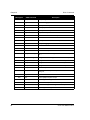
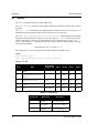
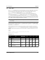
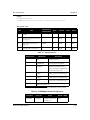
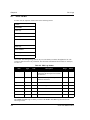
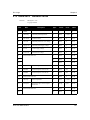
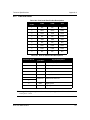
INPUT/OUTPUT CONNECTORS
Antenna input
TNC female jack, 50 Ω nominal impedance
+4.25 to +5.25 V DC, 90 mA max
(output from DL-4 to antenna/LNA)
Power
4-pin LEMO plug
4 W (typical while logging)
COM1
COM2
AUX
Strobes
DE9P connector
DE9P connector
DE9P connector
DE9S connector
+7 to +18 V DC
0.2 W (sleep mode)
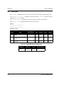
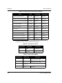
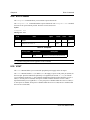
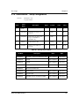
PERIPHERAL POWER OUTPUT
Voltage
≅ supplied voltage
Current
≤ 1 A (internal fuse), non-user replaceable
POWER MANAGEMENT
If the DL-4 is connected to a 12 V battery, the lower cutoff voltage should be set to 10.5 V using the
BATTERY command on Page 99 as the battery should not be allowed to discharge lower than 10.5 V.
If the DL-4 is connected to two batteries, it begins using the one with the higher voltage across its terminals.
When this voltage drops the specified cutoff voltage, the DL-4 switches to the secondary battery (if
available). Once the battery reserves are depleted, the DL-4 shuts itself off.
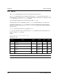
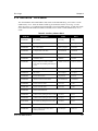
ENVIRONMENTAL
Operating Temperature
-40°C to +55°C (receiver)
Storage Temperature
-40°C to +85°C
Humidity
Not to exceed 90% non-condensing
-20°C to +55°C (display)
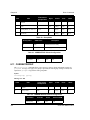
PHYSICAL
Size
180 mm x 160 mm x 70 mm
Weight
1.3 kg
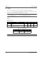
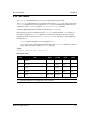
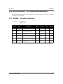
REAL-TIME CLOCK
A real-time internal clock allows the DL-4 to go into low-power ‘sleep mode’ between scheduled datacollection sessions. When the DL-4 is turned on, this clock is initialized using the GPS time reference, and
will indefinitely maintain an accuracy ±1 second and a resolution of 1 second. When the DL-4 is turned off,
the clock begins to drift. To compensate for this, the DL-4 emerges from sleep mode in advance of the next
scheduled data-collection session in order to re-initialize itself.
178
DL-4 User Manual Rev 3