1
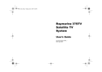
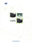
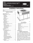
XBA
Bill Acceptor
Installation Guide
&
Service Manual
XBA
Use of Materials Limitations
International Currency Technologies Corporation (ICT) all rights reserved.
All materials contained are the copyrighted property of ICT.
All trademarks, service marks, and trade names are proprietary to ICT.
ICT reserves the right at all times to disclose or to modify any information as
ICT deems necessary to satisfy any applicable law, regulation, legal process
or governmental request, or to edit, refuse to post or to remove any information
or materials, in whole or in part, in ICT's sole discretion.
www.ictgroup.com.tw
XBA
Contents
1. General Information
1-1. Specifications..........................................................3
1-2. Dimensions............................................................. 4
1-3. Harness Application................................................ 5
1-4. Bezel Styles............................................................10
2. Software download and test
2-1. Download Firmware................................................11
2-2. Auto Testing Tool.................................................... 15
2-3. Component Names.................................................28
2-4. Assembling Procedure............................................29
3. Operation
3-1. Operation Flowchart...............................................36
3-2. I/O Circuit................................................................37
4. Maintenance..................................................................40
5. Troubleshooting
5-1. Introduction.............................................................41
5-2. Failed to Power Up.................................................42
5-3. Failed to Communicate...........................................43
5-4. Low Acceptance......................................................44
5-5. Wrong Credit Output...............................................45
5-6. Motor with Strange Sound......................................46
5-7. No Diagnostic LED Status......................................47
5-8. Bill Acceptor Error Code.........................................48
6. Parts and Assembly Views
6-1. Exploded Views......................................................58
6-2. Circuit Board Overviews.........................................64
7. Model Number Configuration.........................................65
www.ictgroup.com.tw
XBA
1. General Information
1-1. Specifications
General
Acceptance Rate
98% or greater
*Note: The acceptance rate excludes notes that are dirty, wet, broken
or wrinkled.
Bill Insertion
Four way acceptable
Transaction Speed
Approx. 2.5 s to stack
Interface
Pulse, MDB, RS232
Installation
Indoor & Outdoor
Electrical
Power Source
12V DC±10%
24V DC±10%
34V DC±10%
Power Consumption
Normal Mode- Standby : 0.15A, 1.8W
Operation: 1.0A, 12W
Maximum: 2A, 24W
Power Saving Mode- Mode 1: 50µA
Mode 2: 15µA
Operation Environment
Operation Temperature: -20°C~65°C
Storage Temperature : -30°C~70°C
Humidity: 30%~95%RH (no condensation)
Mechanical
Bill Box Capacity
Approx. 200 bills
400 bills
Weight
Approx. 1.5kg
Outline Dimension
Refer to page 4
Bill Accepted Width
62~77mm
-3-
www.ictgroup.com.tw
XBA
1-2. Dimensions
t Two Sided Bezel
147[5.79]400bills
115[4.53]200bills
23.5[0.93]
83[3.27]
100.7[3.97]
400pcs.
200pcs.
107[4.21]
132[5.2]
116[4.57]
115[4.5]
238.5[9.39]
]
8[0.3]
22
0.
6[
5.
83[3.27]
50.8[2.00]
48.6[1.91]
6-
104.2[4.10]
(Figure.1)
t TOB Bezel
104.2[4.10]
102[4.0]
117.5[4.63]200bills
300 pcs
100 pcs
106.3[4.18]
69.2[2.72]
25[0.98]
259.8[10.23]
153.3[6.04]
13.2[0.52]
20.2[0.79]
149.5[5.89]400bills
50.8[2.0]
117.5[4.63]
7.9[0.3]
81.2[3.20]
(Figure.2)
101.2[4.0]
Unit : m
: m [inch]
www.ictgroup.com.tw
-4-
XBA
1-3. Harness Application
Interface
Used
Voltage
12VDC
MDB
Pulse
ICT Protocol
Usage
Mode
6
WEL-RS7P02
6
WEL-RM006
7
Power & Data comm.
WEL-RV701
7
Extension Wire
CU-R961
8
Power & Data Comm.
WEL-RV703
8
Extension Wire
WEL-RV702
9
Power & Data Comm.
WEL-RXBA18
9
Extension Wire
CU-R961
Power & Data comm.
34VDC
Normal
12VDC
Sleep
24VAC
Normal
12VDC
Normal
Page
WEL-RV705
Sleep
12/24VDC
Harness
8
(Table.1)
*Data Comm. : Data Communication.
-5-
www.ictgroup.com.tw
XBA
Interface
Used Voltage
Mode
Usage
MDB
12V DC
Sleep
Power & *Data Comm.
WEL-RV705
PIN 1- BLUE..........................+12VDC INPUT
PIN 2- YELLOW..................................Ground
PIN 3- PURPLE.............MDB_WAKE_UP_EN
MOLEX 5559-06P PIN 4- ORANGE............MDB_MASTER_RXD
PIN 5- RED....................MDB_MASTER_TXD
BACK VIEW
PIN 6- GREEN...........................MDB Ground
4
5
6
1
2
3
MOLEX 5559-06P
6
5
4
3
2
1
MOLEX 5557-6R
BACK VIEW
#WEL-RV705
MOLEX 5557-6R
1
2
3
4
5
6
DC 12V MDB
1
2
3
4
5
6
PIN 1- BLUE..................................+12VDC INPUT
PIN 2- YELLOW..........................................Ground
PIN 3- PURPLE.....................MDB_WAKE_UP_EN
PIN 4- ORANGE....................MDB_MASTER_RXD
PIN 5- RED............................MDB_MASTER_TXD
PIN 6- GREEN...................................MDB Ground
*
*
2464 22AWG 6C CABLE
1
16
2
17
3
18
4
19
5
20
6
21
7
22
8
23
9
24
10
25
11
26
12
27
13
28
14
29
15
30
BLK-15*2
PIN 3- BLUE......................................+12V INPUT
PIN 6- ORANGE..................MDB_MASTER_RXD
PIN 14- RED..........................MDB_MASTER_TXD
PIN 17- PURPLE...................MDB_WAKE_UP_EN
PIN 20- YELLOW........................................Ground
PIN 28- GREEN.................................MDB Ground
(Figure.3)
Interface
Used Voltage
Mode
Usage
MDB
12 / 24VDC
Sleep
Power & *Data Comm.
WEL-RS7P02
4
5
6
1
2
3
MOLEX 5559-06P
BACK VIEW
PIN1 BLUE.......................DC+12/24V INPUT
PIN2 YELLOW....................................Ground
PIN3 PURPLE..............MDB_WAKE_UP_EN
PIN4 ORANGE.............MDB_MASTER_RXD
PIN5 RED......................MDB_MASTER_TXD
PIN6 GREEN..............................MDB Ground
6
5
4
3
2
1
MOLEX 5559-6R
BACK VIEW
DC 12/24V MDB
MOLEX 5559-06P
#WEL-RS7P02
MOLEX 5557-6R
1
2
3
4
5
6
2464 22AWG 6C CABLE
1
2
3
4
5
6
PIN3 BLUE.....................................+12V INPUT
PIN6 ORANGE.................MDB_MASTER_RXD
PIN14 RED........................MDB_MASTER_TXD
PIN17 PURPLE.................MDB_WAKE_UP_EN
PIN20 YELLOW.......................................Ground
PIN28 GREEN................................MDB Ground
PIN1 BLUE............................+12VDC INPUT
PIN2 YELLOW....................................Ground
PIN3 PURPLE...............MDB_WAKE_UP_EN
PIN4 ORANGE.............MDB_MASTER_RXD
PIN5 RED.....................MDB_MASTER_TXD
PIN6 GREEN.............................MDB Ground
*
*
1
16
2
17
3
18
4
19
5
20
6
21
7
22
8
23
9
24
10
25
11
26
12
27
13
28
14
29
15
30
BLK-15*2
(Figure.4)
www.ictgroup.com.tw
-6-
XBA
Interface
Used Voltage
Mode
Usage
MDB
34V DC
Normal
Power & *Data Comm.
WEL-RM006
4
5
6
1
2
3
MOLEX 5559-06P
BACK VIEW
PIN 1- BLUE..............................................34VDC
PIN 2- YELLOW.................34VDC Power Return
PIN 3- .............................................................N/C
PIN 4- ORANGE...................MDB_MASTER_RXD
PIN 5- RED...........................MDB_MASTER_TXD
PIN 6- GREEN.....................................MDB Groud
#WEL-M006
MOLEX 5559-06P
*
*
DC 34V MDB
MOLEX 5557-6R
1
2
3
4
5
6
1
2
3
4
5
6
1
16
2
17
3
18
4
19
5
20
6
21
7
22
8
23
9
24
10
25
11
26
12
27
13
28
14
29
15
30
HORN-30
6
5
4
3
2
1
MOLEX 5557-6R
BACK VIEW
PIN 1- BLUE............................................34VDC
PIN 2- YELLOW...............34VDC Power Return
PIN 3- ...........................................................N/C
PIN 4- ORANGE.................MDB_MASTER_RXD
PIN 5- RED.........................MDB_MASTER_TXD
PIN 6- GREEN...................................MDB Groud
PIN 6- ORANGE...............MDB_MASTER_RXD
PIN 14- RED.......................MDB_MASTER_TXD
PIN 16- YELLOW............+34VDC Power Return
PIN 23- BLUE...........................................34VDC
PIN 28- GREEN.................................MDB Groud
(Figure.5)
Used Voltage
Interface
12VDC
Pulse
Mode
Usage
Sleep
Power & *Data Comm.
WEL-RV701
2
1
6
5
4
8
7
9
+AMP
AMP 172340-1
BACK VIEW
DC 12V
3
*
*
#WEL-RV701
AMP 172340-1
1
2
3
4
5
6
7
8
9
PIN 1- YELLOW ........................................ INHIBIT+
PIN 2- GREEN ............................................ INHIBITPIN 5- RED ................................... +12V DC INPUT
PIN 7- BLUE ....................... CREDIT_RELAY (N.O.)
PIN 8- PURPLE ............... CREDIT_RELAY (C OM)
PIN 9- ORANGE ............................................ GND
PIN 1- PURPLE ............. CREDIT_RELAY ( COM)
PIN 2- BLUE ................... CREDIT_RELAY ( N.O.)
PIN 3- RED ................................ +12V DC INPUT
PIN 4- YELLOW ..................................... INHIBIT+
PIN 18- GREEN ........................................ INHIBITPIN 20- ORANGE .......................................... GND
1
16
2
17
3
18
4
19
5
20
6
21
7
22
8
23
9
24
10
25
11
26
12
27
13
28
14
29
15
30
BLK-15*2
(Figure.6)
-7-
www.ictgroup.com.tw
XBA
Interface
Used Voltage
Mode
Pulse
12V DC
Sleep
ICT Protocol
12V DC
Normal
Usage
Extension Wire for WEL-RV701
Extension Wire for WEL-RXBA18
WEL-RU961
1
2
3
4
5
6
7
8
9
2
1
6
5
4
8
7
9
DC 12V
3
2464 22 AWG 6C CABLE
#CU-R961-1
AMP 172332-1
202
202
202
202
202
202
PIN 1- YELLOW...............................INHIBIT+
PIN 2- GREEN.................................INHIBITPIN 5- RED......................... ..+12VDC INPUT
PIN 7- BLUE...............CREOIT-RELAY(N.O.)
PIN 8- PURPLE.........CREDIT-RELAY(COM)
PIN 9- ORANGE....................................GND
+AMP
AMP 172340-1 BACK VIEW
(Figure.7)
Interface
Used Voltage
Mode
Usage
Pulse
24V AC
Normal
Power & *Data Comm.
3
2
1
6
5
4
8
7
9
+AMP
AMP 172340-1
BACK VIEW
AC 24V
AMP 172340-1
1
2
3
4
5
6
7
8
9
#WEL-RV703
WEL-RV703
2464 22 AWG 6C CABLE
PIN 1- PURPLE..............CREDIT_RELAY (COM)
PIN 2- BLUE....................CREDIT_RELAY (N.O.)
PIN 4- YELLOW.....................................INHIBITPIN 16- ORANGE..........................+24V AC (RET)
PIN 18- GREEN........................................INHIBITPIN 23- RED.............................................+24V AC
PIN 2- YELLOW............................................INHIBIT+
PIN 4- BLUE...........................CREDIT_RELAY (N.O.)
PIN 5- PURPLE.....................CREDIT_RELAY (COM)
PIN 5- GREEN...............................................INHIBITPIN 7- ORANGE.................................+24V AC (RET)
PIN 8- RED....................................................+24V AC
BLK-15*2
*
*
1
16
2
17
3
18
4
19
5
20
6
21
7
22
8
23
9
24
10
25
11
26
12
27
13
28
14
29
15
30
(Figure.8)
www.ictgroup.com.tw
-8-
XBA
Interface
Used Voltage
Pulse
24V AC
Usage
Mode
Normal
Extension Wire
WEL-RV702
3
2
1
6
5
4
8
7
9
+AMP
AMP 172340-1
BACK VIEW
AC 24V
AMP 172332-1
202
202
202
#WEL-RV702
1
2
3
4
5
6
7
8
9
202
202
202
PIN 2- YELLOW................................................INHIBIT+
PIN 4- BLUE...............................CREDIT_RELAY (N.O.)
PIN 5- PURPLE.........................CREDIT_RELAY (COM)
PIN 5- GREEN...................................................INHIBITPIN 7- ORANGE.....................................+24V AC (RET)
PIN 8- RED.......................................................+24V AC
(Figure.9)
Used Voltage
Interface
ICT Protocol
Usage
Mode
Normal
12V DC
Power & *Data Comm.
WEL-RXBA18
4
8
7
9
+AMP
AMP 172340-1
BACK VIEW
PIN 1 PURPLE .....................CREDIT RELAY(COM)
PIN 2 BLUE............................CREDIT RELAY(N.O.)
PIN 3 RED........................................+12V DC INPUT
PIN 4 YELLOW.............................................INHIBIT+
PIN 18 GREEN..............................................INHIBITPIN 20 ORANGE..................................................GND
AMP 172340-1
1
2
3
4
5
6
7
8
9
DC 12/24V
1
5
D-SUB(F)
5
4 3 2 1
9 8 7 6
D-SUB 9F TOP VIEW
PIN 2.......................RXD
PIN 3.......................TXD
PIN 5......................GND
#WEL-RXBA18
2
6
ICT PROTOCOL
#WEL-RXBA18
3
PIN1 YELLOW...............................INHIBIT+
PIN2 GREEN..................................INHIBITPIN5 RED............................+12V DC INPUT
PIN7 BLUE.................CREDIT RELAY(N.O.)
PIN8 PURPLE...........CREDIT RELAY(COM)
PIN9 ORANGE......................................GND
PIN 10- YELLOW........................GND
PIN 25- RED................................VCC
PIN 26- BLACK...........................TX11
PIN 27 -WHITE...........................RX11
1
16
2
17
3
18
4
19
5
20
6
21
7
22
8
23
9
24
10
25
11
26
12
27
13
28
14
29
15
30
BLK-15X2
(Figure.10)
-9-
www.ictgroup.com.tw
XBA
1-4. Bezel Styles
t Standard-Bezel
Part Number: A421900-R
48.6[1.91]
2]
15[0.59]
33[1.30]
41.5[1.63]
12.4[0.49]
50.8[2.00]
78[3.07]
102[4.02]
2
[0.
9[0.35]
8[0.31]
5.5
24.5[1.0]
107[4.21]
116[4.57]
84.5[3.33]
83[3.27]
(Figure.11)
t T-Bezel
Part Number: A422000-R
12.5[0.5]
106.3[4.18]
117.5[4.63]
153.3[6.04]
102[4.02]
81.2[3.20]
7.9[0.31]
5.2
[0.2
0]
30.5[1.20]
39[1.54]
50.8[2.0]
78[3.07]
84.8[3.34]
(Figure.12)
www.ictgroup.com.tw
-10-
XBA
2. Software download and test
2-1. Download Firmware
2-1-1. PC
BA
Step 1:
Select Firmware File: File -> Open
(Figure.13)
Step 2:
Select Firmware File & Press Open
(Figure.14)
Step 3:
After opening , screen will display
the file size and Checksum.
(Figure.15)
-11-
www.ictgroup.com.tw
XBA
Step 4:
Connection XBA & PC, turn on the
XBA ,Press “Connect USB”
(Figure.16)
Step 5:
Display Connect
(Figure.17)
www.ictgroup.com.tw
-12-
XBA
Step 6:
To set the DIP. Please select Set Dip
Switch. And selecting DIP, Outside is
a side DIP, Inside is an internal DIP.
(Figure.18)
Press Download.
(Figure.19)
-13-
www.ictgroup.com.tw
XBA
Step 7:
Download Success.
(Figure.20)
Step 8:
After rebooting BA.
Step 9:
BA Version->Read Version. Check
BA Version & Checksum.
(Figure.21)
www.ictgroup.com.tw
-14-
XBA
2-2. Auto Testing Tool
2-1-1. Connection
Preparation before start A. XBA Auto test tool
B. Connection cables(#WEL-RXBA06/#WEL-RHP57)
C. Power source
D. PC(OS Windows XP、Win7)
E. XBA calibration card
POWER
WEL-RV701
WEL-RHP57
(Figure.22)
XBA
PC
Step 1:
Start the tool and make sure the version is the latest one.
(Figure.23)
-15-
www.ictgroup.com.tw
XBA
Step 2:
Enter the version and CheckSUM of this auto test tool.
(Figure.24)
www.ictgroup.com.tw
-16-
XBA
Step 3:
Press Connect USB. Message at upper left corner becomes “USB Connected”.
It means the connection is successful. Turn off and turn on the BA and then the
tool reads BA program version, shows the test items it will perform.
(Figure.25)
-17-
www.ictgroup.com.tw
XBA
Step 4:
Press the 【Start test】 button, the tool starts testing in order.
(Figure.26)
www.ictgroup.com.tw
-18-
XBA
Step 5:
01 Fram Test 、02 I/O Sensor Test、03 Motor Test.
It will appear “NG” if error happens.
(Figure.27)
-19-
www.ictgroup.com.tw
XBA
Step 6:
Calibration Test: Please insert XBA series calibration card.
(Figure.28)
www.ictgroup.com.tw
-20-
XBA
Step 7:
The message shows at the bottom left corner.
(Figure.29)
-21-
www.ictgroup.com.tw
XBA
Step 8:
Bill test. Please insert any Banknote for Accept Testing.
(Figure.30)
www.ictgroup.com.tw
-22-
XBA
Step 9:
Mask LED Test: Please check if the LED flashed the correct color and
press OK or NG in the pop-up window.
(Figure.31)
Step 10:
Stacker Test: Automatically perform stacking for one time, it will be listed
as NG if error happens.
-23-
www.ictgroup.com.tw
XBA
Step 11:
Pulse Test : Please check if the pulse the correct and press OK or NG
in the pop-up window.
(Figure.32)
www.ictgroup.com.tw
-24-
XBA
Step 12:
Dip Switch Test: Please turn on/off the DIP switch according to the message
at the bottom left corner.
(Figure.33)
-25-
www.ictgroup.com.tw
XBA
Step 13:
While testing “10 Cash box Test”, please remove and reinstall the cash box
according to the message at the bottom left corner.
(Figure.34)
Step 14:
Optical anti-stringing design Test, test Optical anti-stringing function.
It will appear “NG” if error happens.
www.ictgroup.com.tw
-26-
XBA
Step 15:
Flash Test There will be error message in the Test information if the
read/write error happens.
The “Issue” shows the result after the entire test:
(Figure.35)
-27-
www.ictgroup.com.tw
XBA
2-3. Component Names
Stack Module
CPU Door
Bill Box Module
M3x8 Screw with washer
CPU Board
ØM3*8 Self-tapping Screw
Black Zinc Plated TP2
M4x12 Screw
Upper Base Module
Lower Base Module
Standard Bezel Unit
www.ictgroup.com.tw
Main Module
(Figure.36)
-28-
XBA
2-4. Assembling Procedure
2-4-1. Disassembly Procedure
Step 1:
Remove bill box.
3
1
2
(Figure.37)
(Figure.38)
Step 2:
Loosen four screws to remove
the bezel.
Step 3:
Remove the cover plate of main unit.
(Figure.39)
(Figure.40)
-29-
www.ictgroup.com.tw
XBA
Step 4:
Loosen four screws to remove cpu
board.
Step 5:
Press the snap on both left and right
sides to remove the upper base.
(Figure.41)
Step 7:
Loosen four screws to remove
transmission module.
Step 6:
Loosen two screws to remove the
Lower Base.
(Figure.43)
www.ictgroup.com.tw
(Figure.42)
-30-
(Figure.44)
XBA
Step 8:
1. Remove the sensor unit top cover.
2. Remove Upper Base Waterproof
Foam. Remove Upper Base Baffle
Board.
Waterproof Foam
Baffle Board
Waterproof
long foam
Sensor Board
(Figure.45)
3. Disassembly IR LED/ Sensor mirror.
(Figure.47)
-31-
(Figure.46)
4. Disassembly
security hook.
(Figure.48)
www.ictgroup.com.tw
XBA
Step 9:
1. Loosen three screws to remove the
Lower Base cover.
2. Remove Lower Base Water Proof
Rubber. Loosen three screws to
remove the LED board.
Lower Base
cover.
Water Proof
Rubber
LED Board
(Figure.49)
(Figure.50)
3. Loosen four screws on the side to
remove the Lower Base Gear
Cover Plate.
(Figure.51)
www.ictgroup.com.tw
-32-
XBA
4. Loosen two screws to remove
Lower Base Waterproof cover.
5. Remove two Plastic Axle Bush to
take rubber wheels out.
(Figure.52)
(Figure.53)
-33-
www.ictgroup.com.tw
XBA
Step 10:
1. Disassembly transmission module.
Loosen screw to remove Sensor
board.
2. Loosen two screws to remove
Block structure Rails.
LED Board
(Figure.54)
4. Remove E-ring. Pull the Belt Axle
out. Remove Belt Roller.
3. Loosen four screws to remove
Bill Sending Motor Set.
(Figure.56)
www.ictgroup.com.tw
(Figure.55)
-34-
(Figure.57)
XBA
5. Rise Stacker Board up. Remove
E-ring. Remove Stacker Board.
(Figure.58)
6. Loosen three screws to remove
Stacker Motor.
(Figure.59)
7. Remove E-ring. Pull the Belt Axle out.
Remove Belt & Belt Roller.
(Figure.60)
-35-
www.ictgroup.com.tw
XBA
3. Operation
Power On
3-1. Operation Flowchart
No
Check
working voltage
10~15V?
YES
First time
wake up?
No
YES
Auto check
All check ok
NO
YES
No
Exception Mode
No
YES
Time Out
Time Out
NO
Device ready
YES
NO
Sleep Mode
YES
Time Out
NO
YES
Sleep Mode
Wait Bill insert
YES
Get pattern
Bill Judge
Sleep Mode
NO
Reject
YES
NO
Laser detect
Input Sensor
Trigger?
YES
Is Fish?
YES
Power ON
YES
Reject
NO
Stack
Stacking OK
NO
Exception Mode
NO
Time Out
YES
Sleep Mode
(Figure.61)
www.ictgroup.com.tw
-36-
XBA
3-2. I/O Circuit
Pulse Interface.
+5VDC~+12VDC
+5VDC
4K7
Credit_Relay_NO
Credit O/P
Credit_Relay_COM
Bill Acceptor
Customer Side
+5VDC~+12VDC
+5VDC
1K
Inhibit I/P
Inhibit+
InhibitHi"TR ON
Lo"TR OFF
TR
Bill Acceptor
Customer Side
Table.11
BA Status
Inhibit
Enable
DIP SW Setting
Inhibit
Active
Inhibit
Active
Control Signal
Low
Low
High
High
Low
High
High
Low
(Figure.62)
-37-
www.ictgroup.com.tw
XBA
MDB Interface.
+5VDC
+5VDC~+12VDC
TXD
1
8
2
7
3
6
4
5
MDB_MASTER_RXD
Bill Acceptor
Customer Side
+5VDC
RXD
1K
+5VDC~+12VDC
8
1
7
2
6
3
5
4
MDB_MASTER_TXD
1K
HiZTR ON
LoZTR OFF
Bill Acceptor
Customer Side
(Figure.63)
www.ictgroup.com.tw
-38-
XBA
ICT Interface.
+5VDC
+5VDC
TXD
TXD
RXD
Bill Acceptor
1K
Customer Side
+5VDC
RXD
TXD
RXD
Hi"TR ON
Lo"TR OFF
Bill Acceptor
Customer Side
(Figure.64)
-39-
www.ictgroup.com.tw
XBA
4. Maintenance
To make sure the bill acceptor always works smoothly, please clean
the internal parts regularly.
To clean the internal parts:
1. Press the buttons on the sides
of bill path and pull the unit out.
Buttons
(Figure.65)
(Figure.66)
2. Use a soft, dry cloth or towel to
clean the bill path and sensors.
Sensors
Sensors
(Figure.67)
(Figure.68)
(Figure.69)
Maintenance Notice
(Any improper maintenance will result invalid warranty.)
Alcohol
www.ictgroup.com.tw
Recommended
Mild, non-abrasive, soap water.
DO NOT USE
Organic solvent , Alcohol, Volatility liquid.
-40-
XBA
5. Trouble Shooting
5-1. Introduction
INTRODUCTION
Check if the unit is
flashing in red error ?
YES
NO
Refer to 5-8
Refer to 5-2
(Figure.70)
-41-
www.ictgroup.com.tw
XBA
5-2. Failed to Power Up
Failed to Power Up
Make sure the input
voltage is 12V DC.
Make sure the harness
connection is correct.
Can power
be applied to unit?
NO
Is there any pin or
harnesses missing?
YES
Replace Power Line
YES
NO
Replace CPU Board
Test the unit by
inserting notes.
(Figure.71)
www.ictgroup.com.tw
-42-
XBA
5-3. Failed to Communicate
Failed to Communicate
Is the connection to PC correct ?
YES
YES
Can power
be applied to unit?
Is unit programmable?
Reload the program
NO
NO
Replace CPU Board
Replace CPU Board
NO
Is the problem
solved?
YES
Test the unit by
inserting notes.
(Figure.72)
-43-
www.ictgroup.com.tw
XBA
5-4. Low Acceptance
Low Acceptance
Clean the bill path.
Make sure the program
is the latest version.
Is the problem
solved?
NO
YES
Replace Sensor Board
Is the problem
solved?
NO
Replace LED Board
Is the problem
solved?
YES
Test the unit by
inserting notes.
NO
Please contact ICT
for technical support.
(Figure.73)
www.ictgroup.com.tw
-44-
XBA
5-5. Wrong Credit Output
Wrong Credit Output
Is credit multiplier
used by the host?
NO
YES
NO
RS232
Pulse
Check firmware for
the denominations.
Check DIP Switch
for proper setting.
Verify credit output
independently.
Is the problem
solved?
NO
Replace Dip Switch
YES
Is the problem
solved?
Replace CPU Board
Test the unit by
inserting notes.
(Figure.74)
-45-
www.ictgroup.com.tw
XBA
5-6. Motor with Strange Sound
Motor with Strange Sound
Make sure belts, pulleys and
wheels are in position.
Is the problem
solved?
NO
Replace Drive
Motor Assembly
YES
Test the unit by
inserting notes
(Figure.75)
www.ictgroup.com.tw
-46-
XBA
5-7. No Diagnostic LED Status
No Diagnostic LED Status
YES
Can power be applied to
the unit?
Refer to 5-2
"Failed to Power Up"
Replace CPU Board
NO
NO
YES
Is the problem
solved?
Replace LED or
Sensor Board
Test the unit by
inserting notes.
(Figure.76)
-47-
www.ictgroup.com.tw
XBA
5-8. Bill Acceptor Error Code
Flash of Diagnostic LED
ONE Red
Bill Jammed (See. 5-8-1)
TWO Red
Disabled From The System
(See. 5-8-2)
General Sensor Error (See. 5-8-3)
THREE Red
THREE+TWO
Red
Hook Sensor Error (See. 5-8-4)
THREE+FOUR
Red
Fish Sensor Error (See. 5-8-5)
A stringing attempt has been
detected. (See. 5-8-6)
FOUR Red
FIVE Red
Stacker Open (See. 5-8-7)
SIX Red
Stacker Error (See. 5-8-8)
Motor Error (See. 5-8-9)
SEVEN Red
(Figure.77)
www.ictgroup.com.tw
-48-
XBA
5-8-1. One Flash
One Flash
Bill Jammed
Clean the bill path.
Is the problem
solved?
YES
NO
Check hook sensor
Is the problem
solved?
NO
Replace Sensor
or LED Board
Test the unit by
inserting notes.
(Figure.78)
-49-
www.ictgroup.com.tw
XBA
5-8-2. Two Flashes
Two Flashes
Disabled From The System
Adjust Dip switch
accordingly or Disable
inhibit signal.
Is the problem
solved?
NO
Replace CPU Board
YES
Test the unit by
inserting notes
(Figure.79)
www.ictgroup.com.tw
-50-
XBA
5-8-4. Three Flashes
Three Flashes
Sensor Error
Clean the bill path.
Is the problem
solved?
NO
Replace LED Board
Is the problem
solved?
NO
YES
Replace Sensor Board
Is the problem
solved?
NO
Replace CPU Board
Test the unit by
inserting notes.
(Figure.80)
-51-
www.ictgroup.com.tw
XBA
5-8-5. Three+Two Flashes
Three + Two Flashes
Hook Sensor Error
Clean the bill path.
Check hook sensor.
Is the hook
in position?
NO
YES
Replace Hook Spring
Is the problem
solved?
NO
YES
Replace Sensor Board
Test the unit by
inserting notes.
(Figure.81)
www.ictgroup.com.tw
-52-
XBA
5-8-6. Three+Four Flashes
Three+Four Flashes
Fish Sensor Error
Clean the bill path.
Is there anything blocking
output sensor?
YES
Remove
NO
Replace output Sensor on
Sensor board
NO
Is the problem
solved?
YES
Test the unit by
inserting notes.
(Figure.82)
-53-
www.ictgroup.com.tw
XBA
5-8-7. Four Flashes
Four Blinks Flashes
A stringing attempt
has been detected.
Clean the bill path.
Power OFF
Power ON
Test the unit by
inserting notes.
(Figure.83)
www.ictgroup.com.tw
-54-
XBA
5-8-8. Five Flashes
Five Flashes
Stacker Open
Remove notes from
the stacker.
YES
Is the problem solved?
NO
Check Stacker Open
Sensor Unit
YES
Is the problem solved?
NO
Replace CPU Board
Test unit by
inserting notes.
(Figure.84)
-55-
www.ictgroup.com.tw
XBA
5-8-9. Six Flashes
Six Flashes
Stacker Error
Remove bills and reset Unit.
Is the problem
solved?
NO
Make sure stacker cap
is in position.
NO
Is stacker cap in position?
YES
Replace Stack Sensor Board
Is the problem
solved?
YES
YES
NO
Replace Stacker Motor
Assembly
Test unit by
inserting notes.
www.ictgroup.com.tw
-56-
(Figure.85)
XBA
5-8-10. Seven Blinks
Seven Flashes
Motor Error
Is there anything blocking
the bill path?
YES
NO
Replace Drive Motor Module
Remove
Is the problem solved?
NO
YES
Replace CPU Board
Test the unit by
inserting notes.
(Figure.86)
-57-
www.ictgroup.com.tw
XBA
6. Parts and Assembly Views
6-1. Exploded Views
XBA Main Module
11
5
10
9
3
8
7
1
4
7
6
5
4
3
2
1
SS399A
S30660
A41990-R
3RMB-SBX85000
3RMB-FAC40000
3RMB-CAS17000
3RMB-DWN24001
3RMB-UPX18001
3RMB-CAS18000
CPU Board
M3x8 Screw with washer
XBA CPU Door
200P Bill Box Module
Standard Bezel Unit
Stack Module
XBA Lower Base Module
XBA Upper Base Module
XBA Main Module
1
6
1
1
1
1
1
1
1
Quantity
8
4
Appellation
9
S30750
4
Part number
10
ØM3*8 Self-tapping Screw Black Zinc
Plated TP2
(Table.2)
M4x12 Screw
11
6
S40310
Order
2
(Figure.87)
-58-
www.ictgroup.com.tw
XBA
Upper Base Module
10
19
17
14
1
12
7
18
1
6
8
13
11
10
9
5
4
15
A4181000-R
Spring
Upper Base Unit
6
1
Quantity
G11170
2
Appellation
1
Ldler Cover
Part number
2
A21280-R
Order
3
3
15
14
13
12
11
10
9
8
7
6
5
4
Z51370-R
A42060-R
G11290-R
C23990-R
Z51330-R
Z51290-R
S20060 D
S30750
A41820-R
A41860-R
A41840-R
A41830-R
A33700-R
A31460-R
Upper Base Waterproof Foam
Upper Base Baffle Board Mylar
Leler Mount
Burglarproof Hook Drawspring
Upper Base Baffle Board
Prism Dust Eraser
Upper Base Dust Eraser
Upper Base Waterproof cover
LED light guide prism
Upper Base Upper Cover
Burglarproof
Leler Mount
Press Roller
1
1
1
2
1
1
2
1
1
2
1
1
4
6
(Table.3)
2
7
16
Z51380-R
Sensor Board
Ø3*8 Self-tapping Screw Black Zinc
Plated TP2
2.3X6 Self-tapping Screw Black Zinc
Plated TP2
17
SS399Hxx
2
18
19
16
(Figure.88)
www.ictgroup.com.tw
-59-
XBA
8
13
3
4
16
14
9
15
21
6
7
1
5
11
10
19
18
2
17
(Figure.89)
9
8
7
6
5
4
3
2
1
S31240
A41940-R
A41910-R
A41960-R
F10940-R
F10880-R
F11250-R
Z51310-R
A42070-R
SS399Gxx
A4189000-R
Lower Base Gear Cover Plate (Left)
M3x4 I Type Screw Black Zinc Plated
Lower Base Gear Cover Plate (Right)
Lower Base Waterproof cover
Optical Shutter (30P)
O Type Gear( M0.7x T15xW2)
O Type Gear( M0.7x T25xW2)
D Type Gear(M0.7xT10xW2)
Lower Base Water Proof Rubber
Roller D Type
LED Board
Lower base Module
1
4
1
1
2
2
2
2
2
2
1
1
Quantity
10
A41950-R
6
Appellation
11
Plastic Axle Bush
Part number
12
A35390-R
Order
13
2
4
Front Roller Axle
1
B15130-R
1
14
S30750
Ø3*8 Self-tapping Screw Black Zinc
Plated TP2
Lower Base Water Proof Rubber
2
S10020
Z51300-R
Lower Base Cover
15
16
A41900-R
M3*8 Screw with washer
20
19
A41970-R
Z51320-R
Waterproof cover light guide
O ring (P3)
2
2
8
17
S30660
E3-E Type Ring
18
21
(Table.4)
-60-
www.ictgroup.com.tw
20
12
Lower Base Module
XBA
19
4
01
Stack Module
3
20
17
2
22
9
28
24
29
14
1
21
7
15
25
27
26
11
28
16
10
11
29
23
8
6
(Figure.90)
18
5
21
(Table.5)
4
4
4
E3-E Type Ring
2
Quantity
S10020
Ø3*8 Self-tapping Screw Black Zinc
Plated TP2
M3x8 Screw with washer
2
Appellation
S30750
Belt Roller T30 Type D
2
M3x20 Round Head Screw with washer
Part number
4
S30660
O Type Gear( M0.7x T25xW2)
4
S31430
5
A20740-R
Belt Roller T20 Type O
1
1
Order
6
F10880-R
Bearings-740ZZ(D7Xd4Xt2.5)
1
3
7
A29850-R
Bill Stacking Structure Pedestal
1
M3x30 Round Head Screw with washer
8
J11140-R
Right Scissors Unit
1
S31700
9
A4198000-R
Left Scissors Unit
1
2
10
C2397000-R
Stacker Motor
2
11
C2398000-R
Bill Sending Motor Set (Right)
Anti-skid Rubber
12
3RMB-MOT21000
Z50530-R
13
3RMB-MOT20000
3
14
28
27
26
25
24
23
22
21
20
19
18
17
16
A42250-R
E50460-R
G11170
A42040-R
A42050-R
B15150-R
B15140-R
B15160-R
F12020-R
A42010-R
A42000-R
SS399Fxx
A42020-R
3RMB-MOT22000
Plastic E3-E Type Ring(3mm)
Belt(140MXL-4.8W)
Spring
Press Roller
Leler Mount
Belt Axle (20T)
Belt Axle Type D (25T)
Belt Axle Type D (30)
Spur Gears(M0.7X12T-D type)
Block structure Rails L
Block structure Rails R
Cash Box Sensor Board
Stacker Board
Bill Sending Motor Set (Left)
6
2
2
2
2
2
2
2
2
1
1
1
1
1
1
15
29
www.ictgroup.com.tw
-61-
XBA
Bill Box Module (200P)
12
11
3
13
2
10
16
9
1
5
4
14
15
8
7
6
(Figure.91)
9
8
7
6
5
4
3
2
1
B10860-R
G1038A-R
A2202A-R
C20280-R
J11160-R
G11580-R
A42170-R
A42180-R
A42120-R
A42100-R
A42110-R
Door Link Spindle
Tensional Spring of Door Link
Door Link
Spring
Slider
Pick
Tensional Spring of Bill Pressed Board
(0.3x3.0x10T)
1/4" Nylon Ball
Bill Pressed Board
Positioned lens
Bill Box Door Plate
Bill Box Top Cover
Bottom Base Module of Bill Box
1
2
2
2
2
1
1
5
4
1
1
1
1
1
Quantity
10
G12040-R
Vortex Spring
Appellation
11
B13600-R
Bills Supporting Board
Part number
12
G11130-R
Order
13
A42130-R
1
1
14
Bill Box Sticker 140 x 67 mm
15
16
(Table.6)
-62-
www.ictgroup.com.tw
XBA
Bill Box Module (400P)
13
10
9
17
11
16
18
8
4
19
12
2
14
7
15
6
1
5
3
(Figure.92)
Order
Part number
Appellation
Quantity
A42170-R
Tensional Spring of Bill Pressed Board
(0.3x3.0x10T)
1/4" Nylon Ball
Bill Pressed Board
1
4
4
1
1
G11580-R
Pick
2
1
4
J11160-R
Slider
2
Bottom Base Module of Bill Box
5
C20280-R
Door Link
2
Bill Box Top Cover
6
A2202A-R
Tensional Spring of Door Link
1
A42110-R
7
B10860-R
Door Link Spindle
1
A42140-R
8
G12040-R
Bills Supporting Board
2
1
9
B14500-R
Bill Box Door Plate
1
2
10
A42160-R
Scissors
1
11
A42150-R
Vortex Spring
Positioned lens
12
C23760-R
A42180-R
13
G12710-R
3
14
S10010
B15060-R
Spring
E2-E Type Ring
Scissors Spindle
1
4
2
1
15
16
G1038A-R
1
17
Bill Box Sticker 140 x 67 mm
18
19
(Table.7)
www.ictgroup.com.tw
-63-
XBA
6-2. Circuit Board Overviews
LED BOARD
INPUT SENSOR
3BA-RSS399Gxx
3BA-RAA399Gxx
3BA-RSS399Fxx
3BA-RAA399Fxx
SENSOR BOARD
3BA-RSS399Hxx
3BA-RAA399Hxx
WEL-RQ705
WEL-RXBA07
FFC-RG12070
MOTOR DECODER
CPU BOARD
CPU BOARD
3BA-RSS399Exx
3BA-RAA399Exx
3BA-RSS399Axx
3BA-RAA399Axx
3BA-RSS399Axx
3BA-RAA399Axx
WEL-RXBA02
(Figure.93)
www.ictgroup.com.tw
-64-
XBA
7. Model Number Configuration
XBA - X X X X X XX X X XX
A
B C D E F G
H
I
J
K
A: Model
E: Bezel
I: Denominations
B: Retention code
F: Coating method
J: Customer
C: Voltage
G: Interface
K: Software Version
D: Bill Box Capacity
H: Currency
(A): Mode
Code
Model
XBA
XBA Series
(Table.8)
(B): Retention code
Code
-
Retention code
(Table.9)
(C): Voltage
Code
Voltage
1
DC 12V
2
DC 24V
3
DC 34V
4
AC 24V / DC 34V
(Table.10)
(D): Bill Box Capacity
Code
Bill Box Capacity
2
200 Bills
4
400 Bills
(Table.11)
-65-
www.ictgroup.com.tw
XBA
(E): Bezel
Code
Bezel
D
Standard Bezel (Two-Sided)
T
T-Bezel
(Table.12)
(F): Coating method
Code
Coating method
P
PVD
N
Non-PVD
(Table.13)
(G): Interface
Code
Interface
M
MDB
P
Pulse
R
ICT002
(Table.14)
(H): Currency : EU. Euro
( I ): Denominations
Code
Denominations
1
1 Denomination
2
2 Denominations
3
3 Denominations
4
4 Denominations
5
5 Denominations
6
6 Denominations
7
4 Denominations
(Table.15)
(J): Customer
Customer
Code
(Table.16)
(K): Software Version : 00~99
www.ictgroup.com.tw
-66-
Taiwan
International Currency Technologies Corporation
Ji-Hong Building, No 24, Alley 38, Lane 91, Nei-hu Rd., Sec. 1, Taipei, Taiwan, R.O.C.
Tel: 886-2-2797-1238 ‧ Fax: 886-2-2797-1634
[email protected] (For Sales) ‧ [email protected] (For Customer Service)
Website: www.ictgroup.com.tw
www.ictgroup.com.tw
2013 International Currency Technologies Corporation
V. 1.0
Part Number: H