1
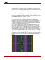
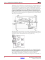
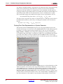
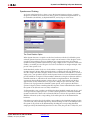
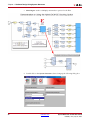
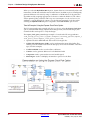
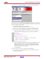
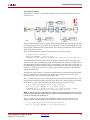
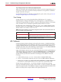
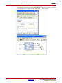
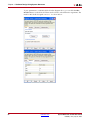
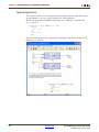
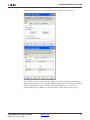
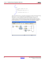
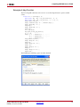
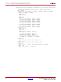
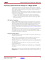
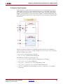
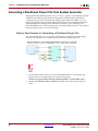
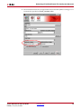
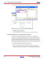
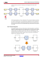
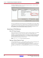
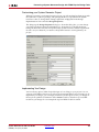
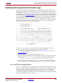
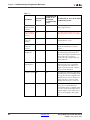
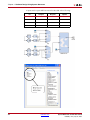
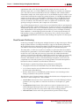
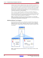
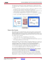
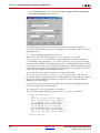
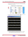
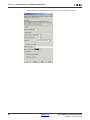
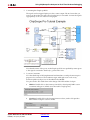
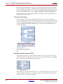
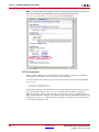
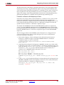
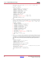
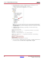
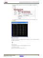
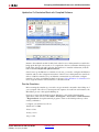
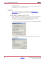
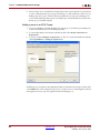
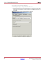
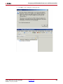
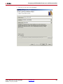
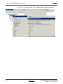
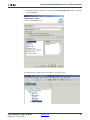
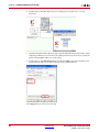
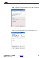
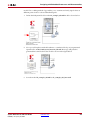
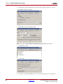
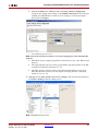
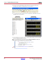
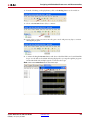
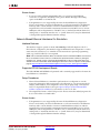
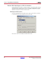
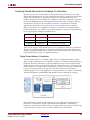
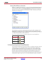
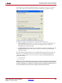
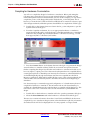
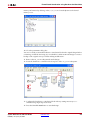
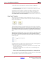
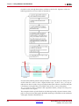
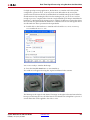
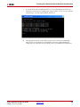
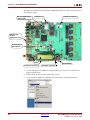
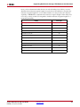
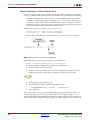
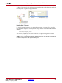
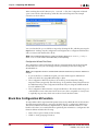
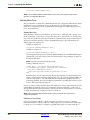
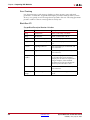
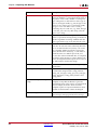
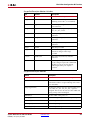
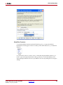
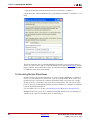
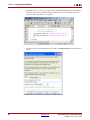
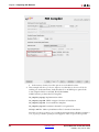
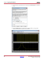
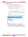
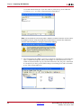
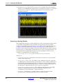
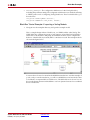
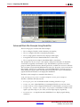
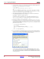
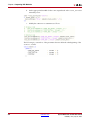
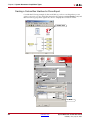
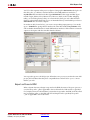
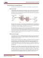
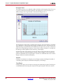
Resetting Auto-Generated Clock Enable Logic
Resetting Auto-Generated Clock Enable Logic
System Generator provides a bit and cycle accurate modeling of FPGA hardware in the
Simulink environment. Several clocking options are available including the default option
Clock Enables. With this option, System Generator uses a single clock accompanied by
clock enables (ce) to keep various sample domains in sync. Multirate clocking is described
in detail in the topic Compilation Results. System Generator models are often included as
part of a bigger system design which need dynamic control for specifying the beginning of
data path sampling. To allow this control within a bigger framework System Generator
token provides an optional ce_clr port in the top-level HDL clock wrapper for resetting
the clock enable generation logic. The figure below shows the reset of the CE4 signal
generation logic after ce_clr signal is de-asserted.
The effect of ce_clr signal cannot be simulated using the original System Generator
design. To model this behavior within Simulink follow the steps below:
1.
Select Provide clock enable clear pin and NGC Netlist Compilation option on the
System Generator token.
2.
Press the Generate button on the System Generator token.
3.
Run the following command from the MATLAB console to produce the post translate
VHDL netlist. Use “-ofmt verilog” with netgen for generating Verilog netlist:
>> !netgen -ofmt vhdl ./<target_directory>/<design_name>_cw.ngc
4.
Bring in the post translate VHDL/Verilog file as a Black Box within Simulink and use
HDL co-simulation to model the effect of asserting ce_clr signal on your design.
ce_clr and Rate Changing Blocks
The ce_clr signal changes the sampling phase of all the multi-sample data signals. This
behavior has the potential of changing the functionality of all rate changing blocks which
rely heavily on the ce signal to have a periodic occurrence. The various rate changing
blocks and their behavior with regards to the de-assertion of the ce_clr signal is
explained in the table below. These blocks were characterized by importing and simulating
the post translate HDL model as a black box.
System Generator for DSP User Guide
UG640 (v 14.2) July 25, 2012
www.xilinx.com
105