1
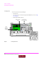
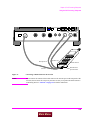
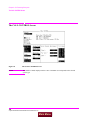
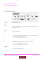
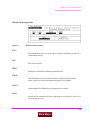
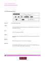
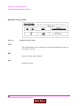
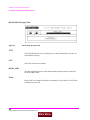
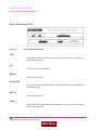
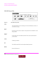
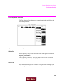
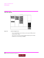
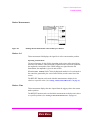
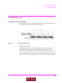
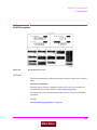
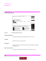
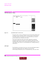
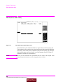
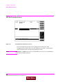
Chapter 23, TX Test Screen
Field Descriptions
TX Freq Error,
TX Frequency
This measurement area is used to display transmitter frequency error or
transmitter frequency.
See Also
“Tune Mode” on page 568
TX Power
Transmitter power measures RF power at the RF IN/OUT port.
Operating Considerations
Maximum signal levels at each port are printed on the front panel.
Only the RF IN/OUT port can be used for measuring TX Power on this screen.
When the Input Port is set to Ant, four dashes (- - - -) appear in place of digits
for this measurement.
Use the Spectrum Analyzer1 to measure low-level RF power (≤200 mW) at the
ANT IN port.
CAUTION:
Connecting a signal of >200 mW to the ANT IN port can cause instrument damage (although
internal protection circuits can typically withstand a short-duration signal of 1 or 2 Watts).
If the overpower circuit is triggered (signified by a warning message at the top of
the screen), remove the signal from the ANT IN port, and press
the MEAS RESET key or turn the Test Set off and on to reset it.
See Also
“Input Port” on page 567 (Operating Considerations)
“TX Power” on page 569
“TX Power” on page 490
“TX Pwr Zero” on page 491
1.
Spectrum Analyzer is an option on some Test Set models.
569
Main Menu