1
MODELS MDA 100, 200
& 400
BEARINGLIFEGUARD
USER MANUAL REV 2.0,
1 / 33
Table of contents
GENERAL INFORMATION ......................................................................................................... 3
DISCLAIMER .......................................................................................................................... 3
SOFTWARE INSTALLATION ................................................................................................ 4
Setting up the 400 PDA .................................................................................................... 4
Setting up SQLite database ............................................................................................. 6
RECREATE- INITIALIZE ................................................................................................... 6
DATABASE ............................................................................................................................. 7
CREATING A USER .......................................................................................................... 7
1.1 Concept of Operations ................................................................................................ 8
Setting up Assemblies ................................................................................................. 9
1.1.1 Creating New Database ....................................................................................... 11
1.1.2 Removing a Database .......................................................................................... 11
Startup .............................................................................................................................................
Logon ..................................................................................................................................... 11
Selecting the Data Acquisition Type .................................................................................. 12
Main Screens ........................................................................................................................ 13
Collecting data-400 ......................................................................................................... 14
Data Collection Modes-100/200 ............................................................................... 16
AssemblySelection- 100/200/400 ............................................................................ 17
Acquisition Settings 100/200 .................................................................................... 18
SEARCH 100/400 ...................................................................................................... 20
Analyzing Data ................................................................................................................. 20
Bearing Information .................................................................................................... 21
Forecast .................................................................................................................. 21
Factors .................................................................................................................... 22
Discriminants ......................................................................................................... 23
TimeHistory ................................................................................................................. 24
SpectrumHistory ......................................................................................................... 26
Settings ........................................................................................................................ 28
Technician Mode ................................................................................................... 28
Analyst Mode .......................................................................................................... 29
Engineering Mode ................................................................................................. 30
OPERATIONAL HINTS .............................................................................................. 30
REFERENCES ................................................................................................................ 33
ASSISTANCE-SUPPORT .............................................................................................. 33
DATA COLLECTION ........................................................................................................... 33
General Gudelines ........................................................................................................... 33
2 / 33
GENERAL INFORMATION
1.1.1Equipment
Familiarization
The system requires an electrical connection between the accelerometer
located on the motor bearing housing load zone and the data acquisition
hardware attached to the local computer. There is no immediate electrical
hazard associated with this connection. However, the user may be close to
rapidly spinning machine elements. It is often advisable to install the
Vibration sensors permanently and run cables out to a BNC access switch
box with barcodes to facilitate safe and rapid data collection.
1.1.2Access
Control
The login name used by the program assigns the user privilege level. Both
the user name and password are case sensitive, e.g. “User” is not the
same as “USER”. The user must successfully log in, to use the program.
The login process will terminate after 3 unsuccessful attempts.
1.1.3Installation
And Setup
The software can be run in networked or standalone mode. In standalone
mode which is the default mode. the SQLite data base server must be
installed and running on the local machine. For more information see
User's Manual.
1.1Stopping
And Suspending Work
The program can be stopped normally by clicking on the window close box
or the exit button on the toolbar. The program cannot be stopped or
suspended normally during a measurement sequence
.
Created with the Standard Edition of HelpNDoc: Free PDF documentation generator
DISCLAIMER
Disclaimer: Please read carefully.
1
1. Bearing failure may be initiated by a variety of factors and has been shown to be
random in nature. Failure patterns conform generally to a Weibull exponential
probability distribution. Bearing LifeGuard estimates are based on the results of
diagnostic assessment of six widely accepted vibration analysis techniques, carefully
averaged and converted to metrics representing a range of optimum to severely
degraded condition. When at maximum they provide the user with credible evidence of
severely degraded bearing surfaces.
3 / 33
The philosophy employed is to convey that information in a clear format to maintenance
personnel so as to provide reasonable advance warning and encourage prompt action
to avert catastrophic operational failure. Given the statistical nature of failure, the
bearing could fail immediately or run for six months. The information is provided and the
assessment of the risk is left to the user. Experience will provide guidance on the
reliability of readings and allow the user to make appropriate adjustments if required.
2. HIGH RISK ACTIVITIES. The standard hardware used for the BearingLifeGuard
system is not intrinsically safe! For use in hazardous areas please contact the manufacturer.
The Software is not designed, manufactured or intended for use, or to be used, as the sole
basis for maintenance or repair decisions in environments in which its failure could lead
directly to death, personal injury, or severe physical or environmental damage, such as in the
operation of nuclear facilities, aircraft navigation or communication systems, air traffic
control, direct life support machines, or weapons systems ("High Risk Activities").
ACCORDINGLY, WE AND OUR SUPPLIERS SPECIFICALLY DISCLAIM ANY
EXPRESS OR IMPLIED WARRANTY OF FITNESS FOR HIGH RISK ACTIVITIES. BY
ACTIVATING THIS SYSTEM YOU AGREE THAT WE WILL NOT BE LIABLE FOR
ANY CLAIMS OR DAMAGES ARISING FROM THE USE OF THE SOFTWARE IN
SUCH APPLICATIONS.
Created with the Standard Edition of HelpNDoc: Full featured Documentation generator
SOFTWARE INSTALLATION
NO ENTRY
Created with the Standard Edition of HelpNDoc: Full featured Help generator
Setting up the 400 PDA
HELPFUL QUICK HINTS:
TO SET UP YOUR MDA 400 PDA HANDHELD COMPUTER
1) When unit is first received from DMC-CT:
All BearingLifeGuard tm software and PDA drivers have been
installed and unit battery has been charged. Plug Unit
into docking station and charge up for minimum of 12 hrs. Subsequent
charges until light on unit is green. Then unit it is ready to go.
For convenience unit should be left in docking station
on trickle charge when not in use.
2) If battery is completely discharged and boots up to calibrate screen,
recharge and follow simple instructions on screen to Calibrate
and reset the Windows tm program. .
Be sure to press Enter on completion of Screen Calibration.
This resets Windows tm and the program settings. Note: if Auto
Load program is installed when unit is turned off/on with Power button the
BearingLifeGuard data collection program will
load automatically on Start Up Caution: a cold or warm boot may cause
loss of data and require reinstalling the program.
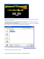
--To reinstall Data Collection Program on 962::
A) Verify USB connection to 962 in Docking Station/Activate Sync link.
4 / 33
Note: In Setting up Active Sync- when prompted, select 'synchronize all
files'.
B) From 962 PDA Install| 962 | pocket PC drivers folder, DAQmxbase CE
setup.exedouble click to load drivers on PDA
.
C) Open mobil device folder to view 962 files- Copy and paste Data collection
V8 to WINDOWS START UP folder on 962. In 962
Windows start up folder.
copy and paste. Check PDA Windows Start up to verify LifeGuard progam Icon is
present. Suggeest: Copy and paste to PDA opening display for convenience in restarting
directly.paste Lifeguard program icon to Windows program display.
Turn unit off and on with power button to verify auto load. If auto load fails, go to
Windows Start up and activate with Icon..
BearingLifeGuard will then load automatically on Start Up using red 'Power
On' button.
Note: if unit is shut down and battery removed. Repeat above procedure for
Auto Load.
3) Enable Barcode scanner by selecting Control Panel-Scanner-To KPDcheck Start Scan2Key when exit. Test by depressing buttons on
side of 962 housing. Scanner will automatically enable at start..
4) To check battery power; go to Control Panel/Power settings.
System defaults are: one minute-Idle.... three minutes-System Idle,,,,
four minutes-Suspend.
Initial Computer Software Installation for PDA-MDA 400
There are four software components which must be loaded onto the computer in order to use the
MDA 400 BearingLifeGuard system. The components are:
1. A compatible SQLite database which is used to store the captured information as well as the
motor
assembly parameters and location. (See below.)
2. The NI DAQmxbase driver software for the data acquisition card.
3. The BearingLifeGuard software for the 400 and the data collection exe.file for the PDA data
collection.
4. Active Sync (If not on PC.)
5. After installation of BearingLifeGuard software, in PDA Install folder activate DAQmx Base CE
setup to install NI drivers and create link to PDA.
6) Using ActiveSync copy and paste MDA400 data collection to 962 in the My Documents file.
7) Using BearingLifeGuard Set up install MDA software in host PC or Laptop.
Initial Computer Software Installation-MDA 100- 200
1. The NI DAQmx driver software for the data acquisition card.
2. Net 2.0 (dotnetfx)
3. Install DBUtilitiy with setup program.
4. Activate DBUtility Icon to open database selection screen.
Select SQLite to open database.
5. Create shortcut by right clicking on DBUtility icon (Start/All Programs)..
6. Install the model 100 software from the BearingLifeGuard software disc on your PC..
7. SQLite is your default database.
8. Run the DBUtility
1. recreate all files
5 / 33
2. recreate users
3. edit table/ users, add new users and passwords. Set Access levels.
4. edit table/company, change company #1 from default to your company
add additional companies as needed.
5. edit table/assemblies, add/create new assemblies ID's, machines,buildings, rooms,
floors as needed. Define each point individually.
9. Install the NIDAQ software. Turn on PDA power and MDA program. Connect and confirm w/
ActiveSync that the program is active and communicating with the DAQ card.
10 Collect data and review.
.
Database-Installation
1.
A copy of SQLite database utility is included. When installed it will create the SQLite database.
Subsequently, when the DbUtility is opened it will display a database selection screen. The user
simply selects and opens SQLite.
2.
Created with the Standard Edition of HelpNDoc: Easy to use tool to create HTML Help files and Help web sites
Setting up SQLite database
Initial Software Installation-MDA 400 only.
There are four software components which must be loaded onto the computer in order to use the
MDA 400 BearingLifeGuard system. The components are:
1. A compatible database which is used to store the captured information as well as the motor
assembly parameters and location. (See below.)
2. The NI driver software for the data acquisition card.
3. The BearingLifeGuard software for the 400 and the data collection exe.file for the PDA data
collection.
4. Active Sync (If not on PC.)
After installation of BearingLifeGuard software, in PDA Install folder activate DAQmx Base CE
setup to install NI drivers and create link to PDA. Using ActiveSync copy and paste MDA400 data
collection to 962 in My Documents file.
Created with the Standard Edition of HelpNDoc: Easily create HTML Help documents
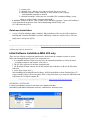
RECREATE- INITIALIZE
In opening the DBUtility program a drop down menu appears and offers
and selecting Edit/Table/ Assemblies -Company- measurement -Summary-Users
6 / 33
The Edit function allows the User to go into the database and edit or add to assemblies, companies or
users etc.
It allows the Administrator to change the content in the Assemblies, Company, tables and Users.
and set the Information screen Alarm display levels.
'Initialize' Creates sample test assemblies for the new user, populating the Unplanned assembly tree and
measurement and summary tables with test samples for use in training or familiarization training.
After training and practice the user may op to clear out the test assemblies and gain more space in the
database.
By using the Re-create feature which clears out all 'test' assemblies and the measurement/summary
tables and
allowing the user to start with a clean database.
CAUTION: BOTH INITIALIZE AND RECREATE WILL ERASE THE EXISTING CONTENT OF YOUR
DATABASE!
Created with the Standard Edition of HelpNDoc: Free CHM Help documentation generator
DATABASE
1.1NO
ENTRY
Created with the Standard Edition of HelpNDoc: Easily create HTML Help documents
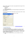
CREATING A USER
7 / 33
The user table contains user names, user password and user type. There
are three user types
Technician
Analyst
Engineer(Supervisor)
The most privileged user type is the Engineer(Supervisor) and the least is
the Technician.
To create a new User: Select |New -Enter new user name in field. |Create
new passwordSelect User Type access level for this User. | Save
Created with the Standard Edition of HelpNDoc: Free PDF documentation generator
1.1 Concept of Operations
Concept of Operations
The bearing lifeguard program uses a database for persistent storage.
Prior to using the bearing lifeguard application the administrator must
select and open the SQLite database. Once opened the database tables
must be initialized using the SQLite DButility application. [See RecreateInitialize in Software Installation.]
The program uses 5 database tables to store information, these are:
User
1.1
8 / 33
Company
Assembly
Measurement
Summary
When first using the system and prior to having collected and stored any
live data, 'a default database exists' with sample assemblies. A supervisor
may elect to erase any sample/test data and start off clean. Do this by
selecting Table | Recreate All from the program menu and answer “OK” to
the dialog –'will destroy all files' click on OK.
Created with the Standard Edition of HelpNDoc: Easily create Help documents
Setting up Assemblies
After installation of DbUtility and BearingLifeGuard software, click on
DbUtility icon in Start | All programs | Bearing LifeGuard. Ó This brings up
the DbUtility menu. Select Table | Edit | Assembly.
This will bring up one of the assembly screens. This confirms that
database has been initialized
and contains sample assemblies with test data. Use the scroll bar to view
the sample ID's stored.
Selecting any of the others will bring up the screens for examination or
editing.
If the assembly screens are blank use initialize to populate them. To
Initialize click on the SQLite DbUtility icon to produce the SQLite menu.
Table | Edit | Initialize
Note the Entry Fields and how they are used to set up an assembly ID
point.
9 / 33
The machine point field identifies the location in the database and may
be a barcode # or a manually entered ID either numerical or text.
The company field contains the Host Facility number created in the
DButility.
The Assembly Name & number describes the machine and location of
the sensor. ex. Pump 2 front drive bearing. Sensor number I-2 etc
Rigid mount - Check if machine is bolted to concrete or solid foundation.
Variable Speed - check brings up option of defining VFD noise
suppression filters,
Gear Drive-allows option of defining gear teeth and ratios to reject gear
mesh noise.
RPM - Enter rotational frequency in rotations per minute.
Accelerometer Sensitivity mv/g.
Cost of failure - best estimate of financial cost of catastrophic or
unscheduled breakdown.
Cost of repair- best estimate of routine scheduled repair, time and
material.
Alarm Levels- User entered settings limits for triggering user warning
alerts displayed on Condition Information Screen.
Building, Floor and Room are entered in last three boxes.
This information now identifies the measurement point so that any data
collected at that point entered as ID will be available as a date stamped
entry in the BearingLifeGuard program on the PC.
10 / 33
Created with the Standard Edition of HelpNDoc: Easily create iPhone documentation
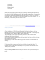
1.1.1 Creating New Database
1.1.1 Creating New Database:
In opening the DBUtility program a list of available databases will be
displayed. The user is requested
to select the database to be used. In 'File name', enter the name of the
new database to be used.
When entered, the user will be taken to the 'new data base' in the DBUtility
program. The user may than proceed to Initialize setting up a new
database which creates a sample company and several demo assemblies
which the user can than Edit add to or delete as required by entering new
Companies, Users and machine Assemblies with new ID's in the
program.
When completed, the New Database will then appear in the list for
selection when either DBUtility or the BearingLifeGuard program are
opened.
Created with the Standard Edition of HelpNDoc: Easily create PDF Help documents
1.1.2 Removing a Database
1.1.2 Removing a Database: SEE USER'S manual. Note: It is
recommended that only an IT supervisor be authorized to remove or
modify an existing database
Created with the Standard Edition of HelpNDoc: Create iPhone web-based documentation
Logon
The user must select a Database Name, and enter a user name and password into the
appropriate text box and then click on the submit button. The Bearing Lifeguard program will
terminate if an incorrect user name or password are entered three (3) times.
The User name and password are created in the DBUtility. Table | Edit | Users. Each user name
is associated with one of three privilege levels, technician, analyst and engineer selected in the
DBUtility. The lowest privilege level is the technician and the highest is the engineer. The
privilege level limits what operations can be performed from the main screen and the settings
screen.
11 / 33
Note: The user name and password are case sensitive and may be different than the computer
login name and password.
The DBUitlity program allows the administrator (Engineer/Supervisor) to modify the user name, user
password and assign a user's privilege level.
After Submit the Select a Database file screen is the first screen a user will see. The database
name is SQLite. The user will select it and Open to start the program..
Created with the Standard Edition of HelpNDoc: Full featured Documentation generator
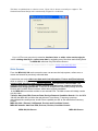
Selecting the Data Acquisition Type
Se le cting a Data Acquisition Source [Applys only to MDA 100 & 200]
12 / 33
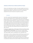
This Data Acquisition Source selection screen, Figure 510, is shown to an analyst or engineer. The
National Instruments DAQCard is automatically assigned to a technician.
Figure 510The user may elect to examine simulated sine or white noise random signals,
select existing data files or collect new data by activating one of the three and clicking Done.
The MDA 400 will show only PDA as the Source.
Created with the Standard Edition of HelpNDoc: Easily create Web Help sites
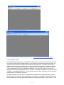
Main Screens
From the MDA 100, 200 main screen the user can access the help system, collect new, or
review and search for previously collected data.
A technician can only collect new data and view Information, Factors and Discriminants
while an analyst or engineer can collect new data, review or search, as well as look at tab
selected time waveform and frequency spectrums for previously collected data. The
Engineer(Supervisor) may also create planned program routes, examine and edit the
database and assign passwords. If the user is assigned the technician privilege level the
Review and Condition Search buttons will be dimmed and unavailable.
In the MDA 400 screen data resides on an external PDA. The Main screen will initially contain
only four tabs:
Transfer data from PDA, Process Data, Review Data and Condition Search. Like the MDA
100-200 the MDA 400 provides the tab selected Time History, Frequency spectrum,
demodulated time and spectra, all with Zoom capability as well as the Information Summary
screen.
MDA 100, 200-- Planned, UnPlanned, Preview and Condition Search
MDA 400 transfer data from PDA, Process, Review, Condition Search
MDA 100,200 Screen
MDA 400 Screen
13 / 33
m
Created with the Standard Edition of HelpNDoc: Free CHM Help documentation generator
Collecting data-400
The Bearing LifeGuard system is configured so that users may elect to have the data collected
by personnel with minimal vibration training, who need only have familiarity with the facility, the
machine locations and have diligent observational and safety skills. The data is stored in the
database for review and examination by the supervisor. When necessary an Analyst may need
to be consulted, but generally, if properly configured, all the information necessary to make a
sound maintenance decision is available immediately. The collection process is made user
friendly and relatively uncomplicated. When required, the Analyst or Engineer may take the MDA
100/200 or a portable MDA 400 PC to the machine site and collect and observe all the vibration
characteristics on location in real time.
The MDA 400 data collection is done by handheld Portable Data Acquisition (PDA) Computer
with inserted accelerometer power supply and data acquisition capability. A barcode scanner is
used to identify the collection point and the data are collected and stored in Flash memory. The
14 / 33
PDA is placed in a docking station and the Supervisor uploads the data to the PC. Once
transferred, the records are removed from the PDA and it is ready to collect more data.
15 / 33
Created with the Standard Edition of HelpNDoc: Easily create Web Help sites
Data Collection Modes-100/200
There are two (2) data collection modes for the MDA 100 & 200, Planned and Unplanned, and
two(2) data Review and Search modes:
1. The Planned mode limits the assemblies displayed to items preselected by a session
planner.
2. The Unplanned mode allows a user to view and select Ad Hoc, any assembly stored in the
database.
3. The Review mode, using a data tree created on collected points, allows the user to
immediately review the informational results for any selected point. Other detailed data is
also available in Review mode.
4. The Search mode allows the Analyst or Engineer to select view only those units that exceed
any one of three
16 / 33
selected criteria. Failure Probability, ( Requires Service attention?, High Dynamic Force.
(Shortening
Machine life which also costs money.) or Financial Risk ( How much money?)
To start collecting data a user clicks on either the planned or un-planned button on the main
window tool bar.
1.1.1.1.1Data Collection (Acquisition) Modes
In the MDA 100 and 200 there are two (2) data acquisition modes, planned or un-planned. The
planned mode lists only those measurements scheduled for a particular session, while the unplanned mode allows the user to sample data on any machine currently in the database. The
user can select the acquisition point using barcode scanner or by manually highlighting the
measurement point on his Planned/Unplanned tree display on his data collector. A plan file is a
text file which contains a list in order of the assembly ID's to be sampled, one assembly ID per
line.
A review mode (Figure 512) in the 100, 200 and 400 brings an assembly tree with all points with
collected data. When a point is selected, the Information Screen immediately appears giving the
user quick assessment of a measured bearing point's condition. The user can continue to
examine all the additional data waveforms and spectra as necessary.
An additional Condition Search mode allows the user to search and display any assemblies
exhibiting levels of % Probability of Failure, Dynamic Force levels or levels of high Financial Risk.
The user selects any of the three search criteria, enters the level and initiates the search. All
units meeting any one of the criteria will be displayed in the database tree. An operation or
measurement is initiated by clicking on the appropriate program tool bar icon.
Figure 513
Created with the Standard Edition of HelpNDoc: Full featured Documentation generator
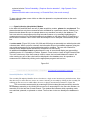
AssemblySelection- 100/200/400
The assembly ID uniquely identifies the tree location to a single sensor location on a particular motor. Note
that there may be more than one sensor on a motor. Selecting an assembly by clicking on the assembly ID
will bring up the next screen which allows the user to change measurement parameters, Figure 514.
1.1.1.1.1The user selects an assembly by scanning ID point location barcode previously stored in
the database assembly,or by clicking the mouse on an assembly ID in the tree view window. An
assembly ID is the last item at each branch. The window title indicates which operating mode
was selected, planned, un-planned or review. The first item in the tree identifys the database in
use.
17 / 33
Created with the Standard Edition of HelpNDoc: Free iPhone documentation generator
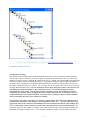
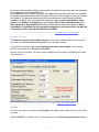
Acquisition Settings 100/200
OAcquisition Se ttings
The default values for Motor Speed and Wide Band Detection are taken from the Assembly database.
The operator is given a chance to enter notes prior to starting the measurements. The user selects the
number of sample averages required, the sample time (0.2 sec. default.) the motor RPM is taken from the
assembly set up but may be manually input by user. To minimize imbalance and misalignment influences
on bearing noise calculations, by default the BearingLifeGuard system uses high frequency energy over
four times rotational frequency to 15kHz . The user may elect to use frequencies from 3 Hz to 15 kHz by
checking Wideband Detection. Once an assembly ID has been selected a new screen will pop up
and display the default settings for the measurement set. The default settings should be
acceptable for most cases. One general exception would be motor speed which should be
measured and entered when recording data on a variable speed motor. In this latter case it is
recommended that a consistant RPM be used each time a reading is taken so that conditions
will be essentially the same from reading to reading.
The operator may enter comments, for example, a description about the motor appearance or
performance information, belt vibration, loose foundation, leaks, etc., into the notes area. Any
comments entered are stored in the database with the measurement data for this reading. Any
VFD or Gear Mesh notch frequencies used in the assembly point set up will be displayed. The
first block represents the number of samples to be captured and averaged. The Duration determines the
bandwidth resolution. Example: 1/0.2 = 5 Hz frequency bandwith. Motor speed is obtained from the
18 / 33
Assemby set up in the DB Utility or may be entered directly in this field block in RPM. This figure will
determine the 4X low frequency cut off used in the HF (High Frequency) energy measurement.
Once satisfied with the information; click on the Collect button to start the data collection
sequence.
The first record will be captured and a plot of the raw data will be presented to the user. The user
must accept the data by clicking "Process this data" in order to continue. If the user closes the
dialog or clicks "Collect data again" the data will be re-sampled and presented to the user again.
If the user clicks on "skip to next assembly" the data collection for this motor will be bypassed.
Once the data is accepted the remaining samples will be read without interruption and a
progress bar will be displayed during the data collection process.
19 / 33
IEPE BIAS FAULT- the MDA systems are configured to measure bias levels on IEPE sensors to
assure the user that the sensor is functioning properly. The nominal bias range is approximately one half
the constant current power supply level. The MDA system is designed to check for bias level and warn
the user if it is within the proper range typically 7 to 15 volts. This is important to verify proper operation
of the IEPE sensor. When bias is out of range a user alert message is displayed warning the user. This
message may be ignored if user is aware that the connection is valid and an IEPE input is not being
used. i. e. A preconditioned sensor signal with zero bias level is connected as the source. The user may
elect 'Continue" and the system will process the AC signal with a zero bias level. The error message
does not effect the processing of the AC coupled portion of the signal.
Created with the Standard Edition of HelpNDoc: Full featured Documentation generator
SEARCH 100/400
The CONDITION SEARCH MODE allows a Supervisor to focus efforts and resources by
quickly identifying machines that require attention. The user chooses criteria for selecting
specific ID locations for closer review. Three criteria are provided which allow review of only
those machine points that exceed specific Probability of Failure, DF (Dynamic Forces) levels,
or $(Financial or safety) Risk factors.
For example: A Supervisor may wish to know which machines have a $ risk which exceeds
$2000 and have POF levels in excess of 40%. By entering the numbers into the fields and
disabling the the DF field by putting it over 10, only those machines with values exceeding those
figures will be brought up for review in an assembly tree.
Created with the Standard Edition of HelpNDoc: Easy CHM and documentation editor
Analyzing Data
Analyzing Data: The Bearing LifeGuard system has been designed to minimize the need
for detailed vibration analysis. The system is designed to allow a technician to identify the
collection point via barcode, connect and automatically power up the accelerometer,
initiate the collection process, observe and validate the vibration waveform, collect the data
20 / 33
and move to the next point. Notes may be taken if needed. A point may also be accessed
by highlighting it on the assembly tree.
On completion of the collection process, the supervisor may review the data, do a search
to identify and further examine deviant points. If there are none worthy of note, the process
is complete. The data has been stored for future reference in the Bearing LifeGuard
database. Problem units revealed in the search process, may be examined in more
detail by the Analyst or Engineer by reviewing the ID Factors, Discriminants or the
time, spectral or demodulated information to identify the cause and correct it. Since
information is available from six powerful diagnostic procedures the vast majority
of problems will be quickly identified and rectified.
Created with the Standard Edition of HelpNDoc: Free help authoring environment
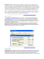
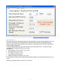
Bearing Information
The Bearing Condition Information window is shown after a data set has been collected or
when the user selects Review or Search from the program tool bar.
The window title indicates the current Assembly Identifier (AssemblyID). In the example
below the Assembly ID is "Bearing 5 HVY ABR"
which is just a test sample. The most recent reading for this Assembly is identified with a date
and time stamp.
Created with the Standard Edition of HelpNDoc: Free Web Help generator
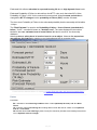
Forecast
The user can select a forecast period, 90 days is the default. Other choices are 60, 120, 180 or
270 days.
Estimated MTTF is a Mean Time To Failure based on the last BC Bearing Condition reading.
21 / 33
Estimated Life reflects reduction in expected bearing life due to high dynamic force levels
Estimated Probability of Failure is derived from the MTTF value such that when BC=10 the
Probability of Failure = 63% for the selected forecast period. When forecast period time is
changed the MTTF changes but the probability of failure (POF) remains constant.
The short term Probability of Failure is the estimated probability that the assembly will fail within
14 days.
The "Risk Estimate" is equal to the Probability of failure * Cost of Actual (unscheduled)
failure, "CoAF", sometimes known as "Avoided cost". The value displayed in the text box
labeled is the user estimated cost of actual failure in $ and is stored in the Assembly
database.
Note that when a safety issue is involved cost is not an object. However the supervisor
may still use this feature by entering a very high estimated risk in monetary units.
Created with the Standard Edition of HelpNDoc: Create HTML Help, DOC, PDF and print manuals from 1
single source
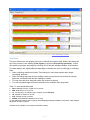
Factors
FACTORS
BC - Indication of actual bearing condition where <1.0 = Optimum(Like new.) and 10 = Near
failure
LE - Indicator of projected bearing life including effects of both BC and DF. where <1.0 = Optimum
and 10 = near failure.
DF-indicates level of life reducing dynamic forces( Ex.Caused by imbalance and misalignment) where
<1.0 = Optimum and 10 = Danger
22 / 33
Created with the Standard Edition of HelpNDoc: Free HTML Help documentation generator
Discriminants
DISCRIMINANTS
LFF = Low frequency acceleration level where <1= optimum and 10 = danger.
HFD = High frequency acceleration energy where <1 = optimum and 10 = damage-surface
roughness..
CFD = Crest factor ratio of peak to rms acceleration where < 1 = acceptable and 10 = early
fatique cracking defects.
KFD = Weighted value of Kurtosis acceleration factor where <1 - smooth and 10 = surface
damage heavy impacts.
EDD = Weighted value of demodulated acceleration envelope where < 1 = smooth and 10 =
Impacting damage
23 / 33
Created with the Standard Edition of HelpNDoc: Free Web Help generator
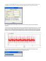
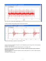
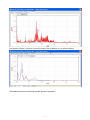
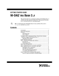
TimeHistory
The time histories are line graphs of the raw or filtered acceleration data. Select tabs along the
top of the screen to view reading (Time signal.) or spectrum(Frequency spectrum.) . Select
the specific signal type and range by selecting one of the tabs along the bottom of the window.
The data displays are slightly different depending on whether the user is collecting or reviewing
data.
· When collecting data there will be a Time History for each data sample and a single
(averaged) spectrum.
· When reviewing data only the last reading of each measurement set and the ten sample
spectrum associated with the last reading are shown.
· To zoom time-left click, drag and outline the section to observe
· To zoom amplitude-right click-select desired zoom multiplier from drop down.
Tabs- To view acceleration data
·
·
·
·
·
·
Raw-Unfiltered incoming signal.3 Hz to 40 kHz.
WB- Wide band 3 Hz to 15 kHz.
LF- Low frequency acceleration (g) or Velocity (in/sec)-Severity
HF- Filtered 4x rotation to 15 kHz.
VHF- Filtered 15 kHz to 40 kHz.
DeMod--Enveloped demodulated 3 Hz to 1kHz.
To view additional readings select settings and add/highlight readings available in drop down. New readings
will appear as tabs on top bar.
150 Milli sec acceleration time sample of defective bearing.
24 / 33
12 milli sec sample of same bearing. Note the impact and ring down.
Twenty five kHz frequency spectrum of same bearing.
NOTE: Instantaneous amplitude or frequency may be displayed by right clicking mouse. Time and spectral
waveforms may be Zoomed
by rolling center mouse control and/or depressing button to move right or left.
No need to look at all the technical details. Immediate Condition assessment report provided to
Maintenance Supervisor.
This report provides all the information required to make a service decision. If no action is taken and failure
occurs it could cost
over $5000 in interruption costs.
25 / 33
Created with the Standard Edition of HelpNDoc: Free PDF documentation generator
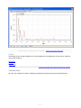
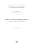
SpectrumHistory
The spectrum plots are averaged results of selected number of time historiy samples in g (rms).
User may view frequency and amplitude of selected spectrum peaks on top display bar as
shown, by right clicking and selecting 'view marker' in drop down menu. Drag the red diamond
below to desired frequency.
To zoom display amplitude, right click and select from drop down menu. To expand section,
click and drag to outline portion to be observed.
Tab Select:
·
·
·
·
·
Raw-.Unfiltered incoming signal.3 Hz to 40 kHz.
WB- Wide band 3 Hz to 15 kHz.
HF- Filtered 4x rotation to 15 kHz.
VHF- Filtered 15 kHz to 40 kHz.
DeMod--Enveloped demodulated 3 Hz to 1kHz
To view additional readings select settings and add readings available. New readings will appear as tabs on
top bar.
Wide band, unfiltered frequency spectrum 1 hz to 25 kHz.
26 / 33
Low frequency frequency spectrum of Velocity( Severity) and acceleration in g on defective bearing.
Demodulated spectrum indicating periodic impact frequencies.
27 / 33
Created with the Standard Edition of HelpNDoc: Easily create Web Help sites
Settings
The settings screen changes based on the user's privlage level. The differences can be seen by selecting
one of the links below.
Technician
Analyst
Engineering
Created with the Standard Edition of HelpNDoc: Single source CHM, PDF, DOC and HTML Help creation
Technician Mode
All users can change the number of readings considered when plotting the factors and discriminants.
28 / 33
Created with the Standard Edition of HelpNDoc: Easily create Help documents
Analyst Mode
If the user is has analyst privileges they can view previously recorded data and select the number of prior
collections to be viewed. Last five to All. The user must then hit Display reading tab and select the specific
date that is to be displayed. Usually the most recent. This is accomplished by selecting a reading number
using the pull down text box in the middle of the screen. The reading number corresponds to the data which
generated the bargraphs on the factors and discriminants screen. Values range from <1 (Optimum) in the
Green to 10 (Near failure) Red. The date|time of the data collection proceeds from left to right. Right click
and select show point values. then holding cursor on the bar will show the specific reading magnitude and
the date time data was collected.
Created with the Standard Edition of HelpNDoc: Full featured Documentation generator
29 / 33
Engineering Mode
If the user has engineering privileges they can view and alter the coefficient table to optimize performance for
specific operating conditions.Note:
Caution: Supervisors are urged to view section on 'Operational Hints' before modifying any of the default
settings. In general the defaults should
be adjusted to compensate for machine RPM and other special characteristics. However actual experience
should be used to reach conclusions
about making changes in coefficients for particular machines. Example: if a facility has 100 machines of the
same type one can
easily begin to look at variability and scatter in the family to create useful norms. Then if one finds that
adjustments should
be made to one or more coefficients the change can be made on all.
tm
The patented Multiple Discriminant Analysis coefficients are provided to allow users to optimize the
tm
benefits of your BearingLifeGuard system.
Created with the Standard Edition of HelpNDoc: Easily create PDF Help documents
OPERATIONAL HINTS
1.1Operational Hints
1.2 Variations with RPM
The MTTF and Life Estimates in BearingLifeGuard are based on remaining cycles to failure. That
is, one hour on a 3600 RPM machine equals represents 216,000 cycles. On an 1800 RPM
machine it represents 108,000. Hence, the 1800 RPM machine will have twice the estimated
MTTF of a 3600 RPM machine in the same condition. All vibration readings, including the impact
and RMS levels measured at the bearing housing load zone will vary with speed, mounting,
bearing design, installation and system orientation. (vertical/horizontal). The BearingLifeguard
system is designed to allow adjustment to minimize the effect of these variables.
30 / 33
The system automatically adjusts the filter band for envelope detection and demodulation. For
RPM 1200 or greater it assumes an accelerometer resonance between approximately 16 kHz
and 24 kHz. For RPM below 900 it assumes that a high sensitivity sensor with a
resonance between 8 kHz and 13 kHz will be used. [For machines operating below 700
RPM see Factory]
Following are some general guide lines and suggestions for adjustments that may be required in
setting up assembly coefficients to optimize system performance.
[Coefficients for POF & DF level screen alarms as well as Cost & Risk $ levels are made
available in the SQLiteUtility. and in the Settings screen located on the monitored point display
screen. The default settings are for rotational speeds of 3600 RPM. ]
1.3The Forecast period:
Manufacturers failure estimates are typically given in number of cycles and then converted to
hours at a given RPM for convenience. Since the Bearing LifeGuard estimates are in hours the
machine speed must be accounted for. The fault detection coefficients are set up for 3600 RPM
and therefore a machine running at 7200 or 1800 will reach the same number of cycles in half or
twice the running time respectively. So forecast period should be set accordingly from 90 to 45
or 180 days and 120 or 270 days respectively. The forecast POF will not change, but both the
‘short term' POF and the MTTF and MTTF-E, based on number of cycles, will. The financial risk
remains the same because it is derived from the estimated cost of failure and the estimated
POF.
1.4Rotational Frequency Coefficient Settings:
L10 bearing life is stated in cycles to failure meaning that estimated bearing life in hours is
inversely proportion to rotational frequency. When rotational frequency is doubled life will be cut
in half. When rotational frequency is cut in half expected bearing life is doubled.
BearingLifeGuard diagnostics vary with frequency also, and they roughly approximate the life
change with rotational frequency.
Measured housing acceleration varies roughly as frequency squared. Therefore we expect to
compensate adjusting coefficients for systems with different rotational frequencies. Experience
indicates that default settings will satisfy most common situations in the range of 1800 to 3600
RPM. To keep estimated cycles to failure approximately the same with RPM we suggest
changing the forecast time period at 7200 to 45 days and 1800 to 180 days etc. Experience will
also dictate changes for specific situations. In general we always recommend erring on the side
of caution. Coefficient are weighted and the weighting will change with rotational speed.
If there is doubt, the specific time waveforms, and spectra are available for examination by the
engineer or analyst to confirm severity prior to shutdown.
Note: On a variable frequency machine when possible, data should be collected at
roughly the same speed for trending consistency
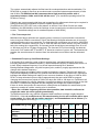
The discriminant levels vary w/RPM.-suggested initial coefficient settings roughly based on
ISO10816-1. Note: As coefficients are increased warning levels and readouts will be more
conservative. (i.e. User will get earlier warnings.) recommendations are as follows: [For
Supervisor/Engineer level only.] Default Settings.
ISO NEAR FAIL (g rms) .015Coefficient RPM-(min/max)
0.050.1
0.10.15
0.150.3
0.3-0.7
3
5
.02
<200
<400
<60
0
<100
0
12001500
17502400
3600
10-20
20-50
5000<72 <1200
00
0
PEAK g
0,2/1500
100200
25-80
1030
2-6
3
2
1
0.5
0.1
C2- KFD2
1
1
1
1
1
1
1
0.5
0.1
31 / 33
0.1/100.
C4- BDF Scale
0.2/100
1
1
1
20-50 1030
1
1
1
1
1
1
5-10
3-7
2
1
0.5
0,1
C5 -DF Scale
0.1/1500
*(see note
50150
C6- DF/HF cont.
0.0/0.6
0.2
0.2
0.2
0.2
0.2
0.2
0.2
0.2
0.2
C7- DF/LF cont.
0.7/4
0.8
0.8
0.8
0.8
0.8
0.8
0.8
0.8
0.8
C9- LE| DF
0.1/0.5
0.2
0.2
0.2
0.2
0.2
0.2
0.2
0.2
0.2
S1- HF Scale
0.25/1500
50200
25-80 1030
4-6
3
2
1
0.5
0.1
S2- ED Scale
500.25/100
200
* LF rms g x mass of housing.
25-80 1030
5-16
5-10
4
1
0.5
0.25
General hints: [Read carefully.]
Coefficients for approximate RPM are set by the Supervisor for each assembly to produce POF
based on measured severity of surface defects. The coefficients may be adjusted to
compensate for anticipated variations in measured acceleration with RPM.[DF] Peak g and
High frequency RMS g [HF] for a given machine, will vary roughly as the square of RPM. When
properly set they should produce 63% POF for a near failure defect condition. Defaults are set
based on measurements made with test machines running at 3600 RPM. Forecast period is
defaulted at 90 days (Deemed a reasonable period for required action.) for machines running
near 3600 RPM. Since L10 beaing design life is specified in cycles, it is reasonable to
estimate a machine running at 7200 RPM will fail sooner and that one running at 1800 or
1200 RPM will run longer with a given defect severity. 90 days is approximately 5 year
MTTF, 45 days 2.5 yrs., 180 10 years and 270 15 yrs. 270 is suggested for machines running <
600 RPM. A supervisor will change the forecast period and coefficients accordingly. (In general
user should adjust to satisfy individual risk tolerance and critical nature of the machine
under test.) .
C6 User selected % contribution of High Frequency energy to lower frequency Dynamic Forces
.(0.2=20%)
C9 User selected Dynamic Force reduction of estimated bearing life at DF max.of 10 (0.2=20%
. 0.5 =50%) Estimated reduction in expected life due to excessive DF.
.
Note: These setting recommendations are provided for guidance only. User experience
will be the most important guide. If you tear down a bearing with surface condition that reflects
lesser or more severe degradation than the discriminants may have indicated the engineer/
supervisor has the ability to go in and adjust the coefficients accordingly. In general raising the
coefficient will make the system more sensitive and provide earlier warnings.They are intended
to provide adequate warning and to allow the user the flexibility to optimize the diagnostic
effectiveness of the system. If a user discovers that the range of adjustment is not sufficient,
please provide feedback to DMC/tech support and that request will be evaluated and if needed, a
change will be made on the basic package and sent free of charge to all users. For machines
operating outside the 200 to 12,000 RPM range users are requested to contact
[email protected]. Important: when an increase in any discriminant is
noted it indicates a degrading condition and a need to monitor the machine more
frequently to observe trend of problem indicated.
32 / 33
Created with the Standard Edition of HelpNDoc: Easily create PDF Help documents
REFERENCES
1)
2)
3)
4)
5)
6)
7)
Rolling Bearing Analysis-3rd Edition, Tedric A. Harris, Wiley- Interscience Publication.
Torrington Fafnir Kilian Service Catalog. 2001 ( Now Timkin Bearing Co.)
Shock & Vibration Handbook, Third Edition, Cyril M. Harris
ISO standard 10816.
Mechanical Failure Prevention Society (MFPT)
62-Virginia Beach, Virginia, US
Update on BearingLifeGuard project.
Copyright 2010, Dynamic Measurement Consultants, LLC
US Patents 8950.6495.4495 & 7.606.673
Created with the Standard Edition of HelpNDoc: Easily create Web Help sites
ASSISTANCE-SUPPORT
The system is provided with a Quick Start User's Manual in addition to the Help Screen. This is
the first place to look for additional information. In addition, the program website has a Frequently
Asked Question (FAQ) area. , if your question is not answered by one of the FAQ's you can email or contact technical support at [email protected] . E-mail questions are
generally answered within one or two business day.
Created with the Standard Edition of HelpNDoc: Create iPhone web-based documentation
DATA COLLECTION
Created with the Standard Edition of HelpNDoc: Free iPhone documentation generator
General Gudelines
Please contact Technical Support @ bearinglifeguard.com
Created with the Standard Edition of HelpNDoc: Free PDF documentation generator
33 / 33