1
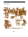
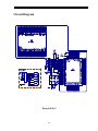
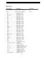
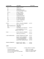
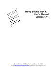
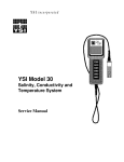
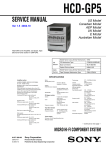
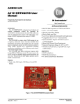
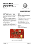
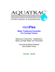
YSI Model 55 Handheld
Dissolved Oxygen System
Service Manual
EMPLOYEE-OWNED
YSI INCORPORATED
Yellow Springs, Ohio 45387 USA
937-767-7241 n 800 765-4974
Fax 513 767-9353
Table of Contents
Service Philosophy
2
Specifications
3
Principles of Operation
4
Probe Operation & Maintenance
5
Calibration
6
Troubleshooting
8
Disassembly Procedures
9
Assembly Drawing
10
Board Assemblies
11
Test Procedures
12
Circuit Diagrams
13
Parts List
15
Warranty and Repair
17
Service Philosophy
The YSI Model 55 is sold as a complete dissolved oxygen measuring system including an attached
probe and either a 12 or 25 foot cable. Most service issues which occur in dissolved oxygen
systems are caused by improper maintenance of the probe or cable. For this reason,
troubleshooting efforts should be initially directed at determining the condition and function of the
probe and cable.
In the event that a service problem is isolated to the meter itself, YSI recommends the replacement
of the entire defective sub-assembly rather than individual components. All replacement systems
are available through YSI; see section entitled Warranty & Repair for details.
2
Specifications
Operating Environment
Medium: fresh, sea, or polluted water
Temperature: -5 to +45oC
Depth: 0 to 12 or 0 to 25 feet (depending on cable length)
Storage Temperature: -10 to +50oC
Material: ABS, Stainless Steel, Acrylic, and other materials.
Dimensions:
Height:
Thickness:
Width:
Weight:
.5 inches
2.2 inches
.5 inches max.
1.7 pounds
(24.13 cm)
(49.53 cm)
( 8.89 cm)
( 3.74 kg)
Power: 9 VDC - 6 AA-size Alkaline Batteries (included)
Approximately 100 hours operation from each new set of batteries
Water Tightness: Meets or exceeds IP65 standards
Extensive testing of the YSI Model 55 suggests the following typical performance:
Temperature
Sensor Type:
Range:
Accuracy:
Resolution:
Thermistor
-5 to +45oC
± 0.4oC
0.1oC
Dissolved Oxygen % Saturation
Sensor Type: Membrane covered polarographic
Range:
0 to 200 % air saturation
Accuracy:
± 2 % air saturation
Resolution:
0.1 % air saturation
Dissolved Oxygen mg/L
Sensor Type: Calculated from % air saturation, temperature and salinity.
Range:
0 to 20 mg/L
Accuracy:
± 0.3 mg/L
Resolution:
0.01 mg/L
3
Principles of Operation
The sensor consists of an acrylic body
with a circular gold cathode embedded in
the end. Inside the gold ring there is a
small chamber containing a porous silver
anode. In operation, this chamber is filled
with a solution of KCl electrolyte
containing a small amount of surfactant to
improve wetting action.
A thin permeable membrane, stretched
over the sensor, isolates the electrodes
from the environment, while allowing
gases to enter. When a polarizing voltage
is applied to the sensor electrodes,
oxygen which has passed through the
membrane reacts at the cathode causing a
current to flow.
The membrane passes oxygen at a rate
proportional to the pressure difference across it. Since oxygen is rapidly consumed at the cathode,
it can be assumed that the oxygen pressure under the membrane is zero. Hence, the force causing
the oxygen to diffuse through the membrane is proportional to the partial pressure of oxygen
outside the membrane. As the oxygen partial pressure varies, so does the oxygen diffusion through
the membrane. This causes the probe current to change proportionally.
It is important to recognize that oxygen dissolved in the sample is consumed during the test. It is
therefore essential that the sample be continuously stirred at the sensor tip. If stagnation occurs,
your readings will be artificially low. Stirring may be accomplished by mechanically moving the
sample around the probe tip, or by rapidly moving the probe through the sample. The rate of
stirring should be at least 1 foot per second.
4
Probe Operation & Maintenance
1. Membrane life depends on usage. Membranes will last a long time if installed properly and
treated with care. Erratic readings are a result of loose, wrinkled, damaged, or fouled
membranes, or from large (more than 1/8" diameter) bubbles in the electrolyte reservoir. If
erratic readings or evidence of membrane damage occurs, you should replace the membrane
and the KCl solution. The average replacement interval is two to four weeks.
2. If the membrane is coated with oxygen consuming (e.g. bacteria) or oxygen evolving organisms
(e.g. algae), erroneous readings may occur.
3. Avoid any environment which contains substances that may attack the probe materials. Some of
these substances are concentrated acids, caustics, and strong solvents. The probe materials that
come in contact with the sample include FEP Teflon, acrylic plastic, EPR rubber, stainless steel,
epoxy, polyetherimide and the polyurethane cable covering.
4. For correct probe operation, the gold cathode must always be bright. If it is tarnished (which
can result from contact with certain gases), or plated with silver (which can result from extended
use with a loose or wrinkled membrane), the gold surface must be restored. To restore the
cathode you may either return the instrument to the factory, or clean it using the YSI Model
5680 Probe Reconditioning Kit. Never use chemicals or abrasives not supplied with this kit.
5. It is also possible for the silver anode to become contaminated, which will prevent successful
calibration and/or operation. To clean the anode, remove the O-ring and membrane and soak
the probe overnight in 3% ammonium hydroxide. Next, rinse the sensor tip and KCl reservoir
with deionized water, add new KCl solution, and install a new membrane and O-ring. Turn the
instrument on and allow the system to stabilize for at least 30 minutes. The same anode cleaning
procedure can be done using a 14% solution of ammonium hydroxide and soak the sensor tip
for 3-5 minutes. If, after several hours of stabilization time, you are still unable to calibrate or
operate the probe, return the YSI Model 55 system to an authorized service center for service.
NOTE:Soaking the anode in this fashion can, over time, errode the silver so that the probe is no
longer functional. It is important, therefore, that the probe not be soaked longer than
specified above.
6. If the sensor O-ring is worn or loose, replace it with the appropriate O-ring provided in the YSI
Model 5945 O-ring Pack. It is recomended that the O-ring be replaced at least 4 times a year
regardless of its physical appearance.
5
Calibration
Before You Calibrate
Before you calibrate the YSI Model 55, be certain that the probe is properly filled with
KCl solution and has a new membrane and O-ring.
To accurately calibrate the YSI Model 55, you will need to know the following information:
1. The approximate altitude of the region in which you plan to take your dissolved oxygen
measurements.
2. The approximate salinity of the water you will be analyzing. Fresh water has a salinity of
approximately zero. Sea water has a salinity of approximately 35 parts per thousand (PPT). If
you are not certain what the salinity of the sample water is, use a YSI Salinity-ConductivityTemperature meter to determine it.
The Calibration Process
1. Ensure that the sponge inside the
instrument's calibration chamber is wet.
Insert the probe into the calibration
chamber.
2. Turn the instrument on by pressing the
ON/OFF button on the front of the
instrument. Wait for the dissolved oxygen
and temperature readings to stabilize
(usually 15 to 30 minuites is required).
Note: It is normal for error messages to
appear momentarily at power up.
3. Use two fingers to press and release the
two Ù Ú keys at the same time.
CALIBRATION CHAMBER
4. The LCD will prompt you to enter the
local altitude in hundreds of feet. Use the
arrow keys to increase or decrease the
altitude.
Example: Entering the number 12 here
indicates 1200 feet.
6
When the proper altitude appears on the LCD, press the ENTER key once to view the
calibration value in the lower right of the LCD; and a second time to move to the salinity
compensation procedure.
7
5. The LCD will prompt you to enter the approximate salinity of the water you are about to
analyze. You can enter any number from 0 to 40 parts per thousand (PPT) of salinity. Use the
arrow keys to increase or decrease the salinity compensation. When the correct salinity
appears on the LCD, press the ENTER key.
Operation
Once the calibration process is complete, the only keys which will remain operational are the
MODE key, the LIGHT key, and the ON/OFF key. You can move back and forth from reading
dissolved oxygen in the mg/L mode or the % air saturation mode by pressing the MODE key. If
you are working in a dark area or have difficulty reading the LCD, press and hold the LIGHT key
to activate the back-light of the YSI Model 55. The ON/OFF key turns the instrument on or off.
NOTE: Each time the YSI Model 55 has been turned off, it may be necessary to recalibrate before taking measurements. All calibrations should be completed at a
temperature which is as close as possible to the sample temperature. Dissolved
Oxygen readings are only as good as the calibration.
8
Troubleshooting
SYMPTOM
1. Instrument will not turn on
2. Instrument will not calibrate
3. Instrument "locks up", keypad is
non-functional
4. Instrument readings are inaccurate
or irratic
POSSIBLE CAUSE
A. Low battery voltage
B. Keypad is defective
C. Main board is defective
A. Membrane is fouled or damaged
B. Probe anode is fouled or dark
C. Probe cathode is tarnished
D. Probe is defective
A. Instrument has rec'd a shock
B. Batteries are low or damaged
C. Main board is defective
A. Cal altitude/salinity are incorrect
B. Probe not in 100% O2 saturated air
during Cal procedure
C. Probe didn’t stabilize long enough
before calibration
D. Probe electrodes fouled or tarnished
5. LCD displays "LO BAT"
6. LCD displays message "ER 0"
A. Batteries are low or damaged
A. Instrument's self-test detects
improper probe voltage during
calibration.
7. LCD displays message "ER 1"
A. Instrument's self-test detects a
variance in RAM
8. LCD displays message "ER 2"
A. Instrument's self-test detects a
variance in ROM checksum
9. LCD displays message "ER 3"
A. Instrument's self-test detects a system
malfunction or component failure
10. LCD displays message "ER 4"
A. Sample O2 concentration is more than
20mg/l.
B. High probe output current
11. LCD displays message "ER 5"
A. Sample O2 concentration is below -0.5
mg/l.
B. Low probe output current
12. LCD displays message "ER 6"
A. Sample saturation is greater than
200%
B. High probe current
13. LCD displays message "ER 7"
A. Sample saturation is less than -3.0%.
B. Low probe output current
14. LCD displays message "ER 8"
A. Sample temperature is more than
9
ACTION
A. Replace batteries
B. Replace keypad
C. Troubleshoot or replace board
A. Replace membrane & KCl
B. Clean anode
C. Clean cathode
D. Replace probe
A & B. Remove battery lid, wait 15
seconds for reset, replace lid.
B. Replace batteries
C. Troubleshoot or replace main board
A. Recalibrate w/correct value
B. Moisten sponge & place in Cal
chamber w/ probe & Recal
C. Recalibrate after 15-30 minutes warmup time
D. Clean probe electrodes or replace
probe
A. Replace batteries
A1. Clean probe electrodes and retry
A2. Replace probe
A3. Replace main board
A1. Remove battery lid, wait 15 seconds
for reset, replace lid.
A2. Replace main board
A1. Remove battery lid, wait 15 seconds
for reset, replace lid.
A2. Replace main board
A1. Remove battery lid, wait 15 seconds
for reset, replace lid.
A2. Replace main board
A. Recalibrate using correct altitude and
salinity compensation
B1. Service probe electrodes and retry
B2. Replace probe assembly
A. Recalibrate using correct altitude and
salinity compensation
B1. Service probe electrodes and retry
B2. Replace probe assembly
A. Recalibrate using correct altitude and
salinity compensation
B1. Service probe electrodes and retry
B2. Replace probe assembly
A. Recalibrate using correct altitude and
salinity compensation
B1. Service probe electrodes and retry
B2. Replace probe assembly
A. Reduce the sample temperature
SYMPTOM
15. LCD displays message "ER 9"
POSSIBLE CAUSE
+46oC.
B. Probe thermistor defective
A. Sample temperature is less than -5oC.
B. Probe thermistor defective
10
ACTION
B. Replace probe assembly
A. Increase sample temperature
B. Replace probe assembly
Disassembly Procedures
Refer to the Assembly drawing on the next page before attempting to disassemble the meter case.
Follow these steps to disassemble the meter case:
STEP 1 -- Place the instrument face down on a flat cloth-covered surface. Use a phillips screw
driver to completely remove the screw located at the bottom of the hand strap.
STEP 2 -- Using a standard screwdriver or a small coin, loosen the battery lid screw and remove
the battery lid and all six AA-size batteries.
STEP 3 -- With the instrument face down on the flat, cloth-covered surface, place two fingers into
the battery chamber and your other hand over the cable strain-relief. Pull straight up on the battery
chamber to seperate the case halves. Unplug the power connector from the PC Board.
NOTE: Because the Model 55 is water tight, the case halves will be relatively difficult to
separate.
STEP 4 -- The main PC Board is held in place by a single phillips screw located in the center of
the board. Remove the screw, and gently pull the PC Board away from the front case.
NOTE: The leads on the cable which connect to the main PC Board are quite short. Be
careful not to damage the terminal connectors when you pull the PC Board away from the
front case.
STEP 5 -- Carefully slide the probe cable terminal connector out of its mating connector. Make
note of the wire color configuration so that the connectors can be correctly re-installed later.
STEP 6 -- To separate the probe cable from the front case, unscrew the outer portion of the strain
relief (that portion which does not make contact with the front case). Slide the spiral portion of the
strain relief down the cable toward the probe. Next, unscrew the remaining portion of the strain
relief from the front case.
STEP 7 -- To separate the LCD from the main PC Board, squeeze the four plastic off-set spacers
and slide the LCD PC board away from the main board one corner at a time. Next, remove the
four small phillips screws from the back of the LCD and remove the LCD from its clear plastic
frame.
STEP 8 -- To remove the keypad from the front case, use a small phillips screwdriver to remove
the screws from the keypad's metal backplate; then lift the keypad away from the front case.
11
Assembly Drawing
1
2
3
4
6
5
7
3
Bubble Number
1
2
3
4
5
6
6
7
Item Number
055201
055203
055204
055202
055219
055205
055206
055210
Description
Front Cover Assembly W/Keypad
Main Board Assembly W/055212 Display
Case Hardware Kit
Rear Cover Assembly
Sponge
Probe Assembly, 12 Foot
Probe Assembly, 25 Foot
Battery Hardware Kit
12
Board Assemblies
(PCB-A) Main Board
(PCB-B)Display Board
(PCB-C)Keypad Board
13
Test Procedures
System Test
The Model 55 and it’s probe can be easily tested using the YSI 16423 Test Box. If a test box
isn’t available, the following quick test can be used to verify the system’s operation.
1. If necessary, service the probe’s electrodes. Follow the instructions on page 5.
2. Install a fresh membrane and KCl solution. Place the probe in its calibration chamber.
3. Turn the system on and allow it to stabilize for 30 minutes.
4. Calibrate the system as described in the Calibration section of this manual.
5. With the probe in the calibration chamber, check the displayed reading for stability. Erratic or
drifting readings indicate a possible problem. See the Troubleshooting section for help.
6. Place the probe in a zero oxygen environment. The display should decrease rapidly and reach 0
±2% in 7 minutes or less.
A zero oxygen environment can be obtain by taking a reading in pure nitrogen gas, in a sodium
sulfite solution, or in a BOD bottle filled with 350 mL of distilled water in which 3 to 7 grams of
active dry yeast has been dissolved and allowed to consume the oxygen (about 5 minutes).
Probe Test
The probe thermistor can be tested by measuring its resistance in a temperature controlled bath
and comparing the reading to the chart below. With the probe disconnected from the instrument,
connect a precision ohm meter to the Red and Black probe wires. All readings are ± 10 ohms .
Bath temperature
Degrees Celsius
5
10
15
20
Resistance
in Ohms
5721.11
4484.22
3540.50
2815.03
Bath temperature
Degrees Celsius
25
30
35
40
Resistance
in Ohms
2253.30
1815.32
1471.56
1200.00
Electrical leakage between the sensor electrodes and/or the thermistors can cause system failures.
Before using the test below, remove the probe’s membrane and rinse the electrodes with distilled
water. Then, thoroughly dry the sensor end, inside and outside, with compressed air or a soft towel
before testing.
Ohm Meter Lead #1
Green (silver anode)
Green (silver anode)
White (gold cathode)
Green, White, Red
Green, White, Red
Ohm Meter Lead #2
White (gold cathode)
Red (thermistor)
Red (thermistor)
Thermistor Tube
Stainless steel probe body
14
Resistance Reading
200 meg ohm or greater
200 meg ohm or greater
200 meg ohm or greater
200 meg ohm or greater
200 meg ohm or greater
Circuit Diagram
Board-A
15
Circuit Diagram
Boards B & C
16
Parts List
Circuit Symbol
Description
YSI Order #
PCB-A & PCB-B................MAIN BOARD W/DISPLAY.........055203
PCB-A.............................MAIN BOARD ASSEMBLY.........
R1..................................... RES,1M,5%,1/4W
R2..................................... RES,68K,5%,1/4W
R3,R13,R15...................... RES,100K,5%,1/4W
R4..................................... RES,10M,5%,1/4W
R5..................................... RES,15K,5%,1/4W
R6..................................... RES,180K,1%,1/4W
R7..................................... RES,154K,1%,1/4W
R8..................................... RES,787K,1%,1/4W
R9..................................... RES,232K,1%,1/4W
R10................................... RES,196K,1%,1/4W
R11................................... RES,715K,1%,1/4W
R12................................... RES,220K,5%,1/4W
R14................................... RES,4.02K,1%,1/4W
R16,R17 ........................... RES,120,5%,1/4W
R18................................... RES,180,5%,1/4W
R19................................... RES,17.2K,1%,1/4W
R20................................... RES,750K,1%,1/4W
R21................................... RES,261K,1%,1/4W
R22................................... RES,127K,1%,1/4W
R23,R25,R27.................... RES,1K,1%,1/4W
R24................................... RES,18.7K,1%,1/4W
R26................................... RES,78.7K,1%,1/4W
R28,R30 ........................... RES,34.8K,1%,1/4W
R29................................... RES,23.2K,1%,1/4W
R31................................... RES,121K,1%,1/4W
RN1.................................. RES SIP,100K
L1..................................... COIL,220uH,10%,1/2W
C1,C12,C13,C14,C15 ..... CAPR,.1uF
C2,C3............................... CAPR,CER,20pF
C4 .................................... CAPR,ELE,22uF,16V
C5,C10............................. CAPR,ELE,100uF,16V,105OC
C7 .................................... CAPR,FILM,.47uF,5%,50V
C8,C9,C19....................... CAPR,FILM,.1uF,100V
C11 .................................. CAPR,ELE,10uF,25V
C16 .................................. CAPR,FILM,.33uF,50V
C17 .................................. CAPR,FILM,.47uF,100V
D1,D2,D3,D4,D5 ............. DIODE,1N4148A
17
055211
Circuit Symbol
Description
X1 .................................... CRYSTAL,2.000MHz
Q1 .................................... TRSTR,A733P118C
Q2 .................................... TRSTR,M945
U1 .................................... IC,EXCL,XLS93C46P
U2 .................................... IC,MOTR,MC68HC705C8S
U3,U11............................. IC,NATL,LM358N
U4 .................................... IC,TOSH,TC4011B
U5 .................................... IC,S81250HG9485
U6 .................................... IC,HARR,DC8069J027
U7 .................................... IC,HARR,7663SACPA
U8 .................................... IC,TLDN,TSC7660CPA
U9 .................................... IC,TLDN,TSC500CPE
U10 .................................. IC,NATL,CD4053BCN
U12 .................................. IC,PMI,OP177GP
YSI Order #
PCB-B.................................... DISPLAY BOARD ASSEMBLY....... 055212
R32................................... RES,357K,1%,1/4W
D6,D7,D8,D9,D10,D11.... LED,GREEN
U13 .................................. IC,HD61603
LCD1 ............................... LCD DISPLAY (P/N 0701032) ......... 055214
.... LCD HOLDER (P/N 1701150)
ZEBRA CONNECTOR ................ ......... 055215
PCB-C ................................... KEYPAD BOARD ASSEMBLY ....... 055213
KEYPAD (P/N 0801081)................... 055216
CASE COMPONENTS........ SPRING TERMINAL,BATTERY...... 055217
FRONT COVER ASSEMBLY .......... 055201
REAR COVER ASSEMBLY ............. 055202
** CASE HARDWARE KIT.............. 055204
## BATTERY HARDWARE KIT ...... 055210
PROBE ASSEMBLIES...........WITH 12 FOOT CABLE ................... 055205
WITH 25 FOOT CABLE .................. 055206
NOTE:
** Case hardware kit includes:
1 Case gasket,custom
1 PCB screw,self-threaded,BT,#4
1 Case screw,metric,M3x1.5x42.5mm,custom
1 Case screw o-ring
18
## Battery hardware kit includes:
1 Battery cover,molded
1 Battery screw,stainless,custom
1 Battery cover gasket,custom
Only parts with YSI order numbers are available from YSI.
19
Warranty And Repair
The YSI Model 55 Handheld Dissolved Oxygen Meter is warranted for two years from date of
purchase, against defects in materials and workmanship, exclusive of batteries. YSI Model 55
dissolved oxygen probes and cables are warranted for one year from date of purchase, against
defects in material and workmanship.
YSI products should be serviced by YSI Authorized Service Centers. Service by nonauthorized technicians will void the manufacturer's warranty.
If you are experiencing difficulty with any YSI product, during or after the warranty period, contact
the YSI dealer from whom you purchased the product, the YSI European Service Center or the
YSI Technical Support Department. If a YSI product is returned for service during the warranty
period, please supply proof of purchase.
YSI Incorporated
Repair Center
1725 Brannum Lane
Yellow Springs, OH 45387
YSI European Service Center
Lynchford House
Lynchford Lane
Farnborough, Hampshire
GU14 GLT, England
Phone 937 767-7241
800 765-4974
Fax
937 767-9353
Phone 44 252 514711
Fax
44 252 511855
YSI PART# 055223
DWG A55223 Rev. C
20