1
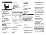
OPERATING INSTRUCTIONS
RC2108
Please maintain these instructions and
review them before using the unit:
!
Warning:
1. This unit is panel mounted type with its
output terminals getting connected to the
host equipment. Such equipment shall also
comply with basic EMI/EMC and safety
requirements like BSEN 61326-1 and BSEN
61010 respectively.
2. To avoid electric shock, power supply of the
unit should be kept off while wiring. Wiring
should be done strictly as per the terminal
layout, given in the manual.
3. Use lugged terminals to meet M3 screws.
4. The unit does not have a built-in fuse.
External fuse with a rating of 275VAC/1A is
recommended.
!
Caution:
1. This unit is not intended for outdoor use.
2. The power connection cable must have a
cross-section of atleast 1mm2 and insulation
capacity of atleast 1.5kV.
3. The output connections must not be loaded
beyond the specified values/range.
4. Avoid inflow of dust and contact of conductive
material with the internal circuitry of the unit.
5. The unit must not operate in presence of
heating sources, caustic vapors, oil, steam,
vibration or impact etc.
6. Clean the equipment with a clean soft cloth,
do not use any organic cleaning agent. Care
must be taken to avoid entry of water into the
circuitry through the ventilation holes.
Terminal Connections:
Specifications:
DISPLAY
4 digits, 0.5'' height, red 7 segment LED.
SUPPLY VOLTAGE
90 to 270V AC/DC
24V AC/DC
RATE MODE
RPS, RPM, RPH (programmable).
RANGE
4 to 9999 RPM.
INPUTS
3-30 VDC from Proximity switches (PNP),
Encoders, Potential free contacts, Limit
switches etc..
SETPOINTS
2 (Low alarm and High alarm).
SCALE FACTOR
Programmable from 0.001 to 9.999 x 10n
n = 0, 1, 2, -3, -2, -1.
MAXIMUM INPUT SPEED
3.5kHz.
LED INDICATION
Low alarm status,
High alarm status.
ACCURACY
±0.05 %.
SENSOR SUPPLY
12 VDC(±10%) , 30 mA. Short circuit
protected.
CONFIGURATION LOCK
via rear terminals.
OUTPUT
1 C/O each for high and low alarm.
HOUSING
Flame retardant plastic.
OPERATING TEMP.
Operating: 0 to 50OC.
Storage: -20 to 75OC.
HUMIDITY
95% RH
WEIGHT
approx 200 gms
Panel Cutout
68
72
72
10
115
Short for Config
3
1
2
+12V
CNT
6
5
4
GND CONFIG
13
+
L
14
-
N
NO1 COM1 NC1
7
NO2 COM2 NC2
11
10
9
8
RELAY1
12
RELAY2
Description
Terminal
69
1. To select scale factor mantissa
Default : 1.000
+12VDC sensor supply
Key press
2
Count input
4
GND
Scale factor
mantissa
4-5
7-8-9
Short to enter configuration
NO - COM - NC of relay1- low alarm
10 - 11 - 12 NO - COM - NC of relay2- high alarm
L-N
(+) - Neutral (-)
Live
Display
Description
Set between
0.001 to 9.999 as
described above.
*
2. Press key to select scale factor
exponent
Default : 0
Scale factor
exponent
0
10 = 1
*
10 1 = 10
Press
*
Input connection for proximity sensor:
1
+12V
2
102 = 100
Press
*
With PNP sensor:
10-3 = 0.001
Press
3
CNT
4
5
*
6
GND
10 -2 = 0.01
Press
*
PNP
10-1 = 0.1
Press
NOTE: dp indicates -ve*sign.
With NPN sensor:
+12V 1k
2
3
CNT
4
5
6
GND
NPN
69
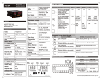
CONFIGURATION SCHEME (parameter setting)
To enter configuration scheme:
1) Short terminal no 4 & 5
2) Turn power ON.
3) Program configuration setting as per
instructions below:
1
1
Overall Dimensions:
Setting numerical values:
'*' indicates blinking digit. The blinking digit,
increments by 1 for every press of the key and
rolls over from 9 to 0. The blinking shifts to the
next digit (right) for every press of key. Using
these keys user can set the required value.
Note: Sensor color codesRed --> +12V, Green --> CNT, Black --> GND
Brown --> +12V, Black --> CNT, Blue --> GND
3. Press
key to select Power ON delay
Default : 000
Power
ON Delay
000 to 999 sec
*
Power ON delay: If alarm condition is present
at power ON, the alarm output will be activated
only after the time set as, Power ON delay.
Document name: Operating/1007/RC2108/version 3 OP-114-V03 Pg. 1 of 2.
Key press
4. Press
Display
Description
key to select Alarm delay
Default : 000
Alarm Delay
000 to 999 sec
*
key to select Reset all
key to select Hysteresis
Default : 05
00 to 99 least
counts.
Hysteresis
*
Press
Press
*
No Action
*
No Action
Press
*
Press
No Action
*
Press
No Action
Press
key to select Resolution
Default : 1
Resolution
*
Press
Press
*
Press
*
7. Press
key to select Mode
Default : 1 (RPM)
RPM
Mode
*
RPH
Press
*
Press
Press
for 3sec to set High Alarm value
Default : 9999
High Alarm value
To quit configuration:
1) Turn power off
2) Remove link between terminal no 4 & 5
3) Turn power on
Note:
1. If input speed is above the indication range,
display indicates 1 in the MSD position.
2. If input speed is below the indication range,
display indicates 0.
*
The blinking digit increments by 1 for every press
of the key & rolls over from 9 to 0.
The blinking shifts to next digit (right) for every
press of key. Using these keys user can set
the required value.
Press key to enter the Low Alarm value &
come out of programming for Low Alarm.
NOTE: High Alarm value should always be
greater than the Low Alarm value. If high
alarm value is set lower than the low alarm
value or vice versa, the unit will not come out
of alarm programming, till the values are
corrected.
TO READ ALARMS
Key press
(MOMENTARY)
Name /
Description
Display
Press
Low Alarm value
Press
High Alarm value
NOTE: Maximum display time is 3 sec.
TYPICAL APPLICATION:
RPS
*
*
All parameter values
set to factory setting
If terminal no 4 & 5 are shorted at
power on, rate indicator will go in to the
configuration mode. To quit configuration setting
mode, turn power off, remove link between 4 &
5 & switch power on.
*
*
The blinking digit increments by 1 for every press
of the key & rolls over from 9 to 0. The blinking
shifts to next digit (right) for every press of key.
Using these keys user can set the required value.
Press key to enter the Low Alarm value &
come out of programming for Low Alarm.
No Action
By pressing key now, all parameters will
reset to factory settings and display will go to
step 1 (scale factor mantissa setting).
Data available:
Example 1:
Diameter of the measuring wheel = 10cm.
The proximity switch generates 1 pulse / rev. of
the measuring wheel.
Low Alarm value
*
Press
6. Press
for 3sec to set Low Alarm value
Default : 0000
key to complete configuration.
*
Low Alarm is activated when Rate < = LA value.
It turns off when, Rate > (LA value + Hysteresis).
High Alarm is activated when Rate >= HA value.
It turns off when, Rate < (HA value - Hysteresis).
TO SET ALARMS
No Action
Reset all
Press
dp indicates Alarm delay.
Power ON delay: When alarm condition
occurs, the alarm output will be activated only
after the time set as alarm delay.
Note: At Power ON, the higher of the two delay
values is considered.
5. Press
8. Press
Objective: To display the delivery rate of the cord
(meters / minute).
LO
selec
RC2108
HI
LOW
Proximity
Switch
Measuring
Wheel
HIGH
Calculations:
Circumference of the wheel =
3.142857 x 0.1 = 0.3142857m.
Therefore, the length of the rope delivered /
revolution is 0.3142857m. Since the proximity
switch gives 1 pulse / revolution, the display
should increment by 0.3142857 for every pulse.
Therefore, scale factor = 3.142857 x 10⁻¹.
Set scale factor mantissa = 3.14285
Exponent = 10-1
The RC2106 will show rate in meters / minute.
Example 2:
In the same application, if 60 PPR encoder is
fitted instead of proximity switch then:
a) The length of rope delivered per revolution is
0.3142857m.
b) The number of pulses / revolution = 60.
c) Length of rope delivered / count pulse =
0.3142857 / 60 = 0.005238m.
The display should increment by 0.005238 for
every pulse.
Therefore, scale factor = 5.23800 x 10⁻³.
Set scale factor mantissa = 5.23800
Exponent = 10-3 for required display.
Selec Controls Pvt. Ltd.
Specifications are subject to change, since development is a
continuous process
Telephone: +91-22-40394200 / 40394202
Fax: +91-22-28471733
Toll free: 1800 227 353
Website: www.selec.com
Email: [email protected]
Operating/1010/RC2108/OP114-V03
(Page 2 of 2)