1
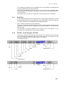
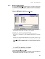
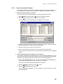
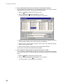
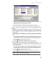
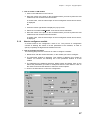
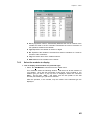
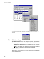
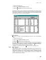
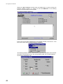
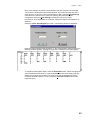
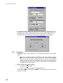
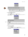
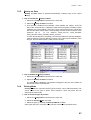
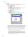
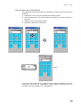
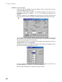
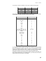
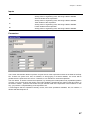
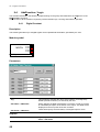
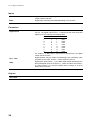
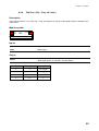
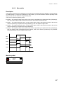
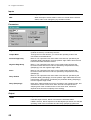
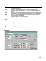
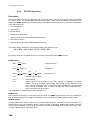
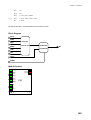
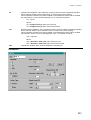
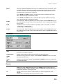
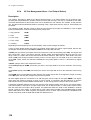
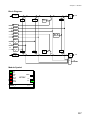
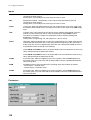
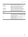
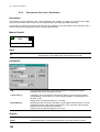
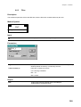
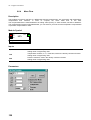
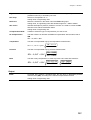
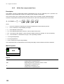
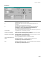
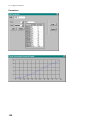
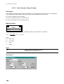
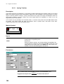
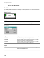
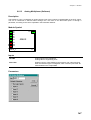
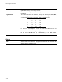
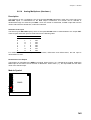
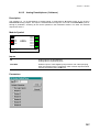
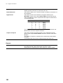
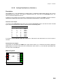
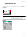
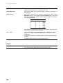
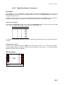
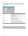
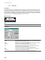
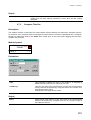
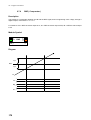
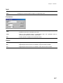
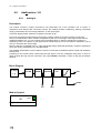
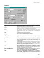
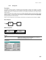
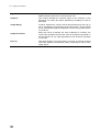
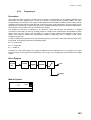
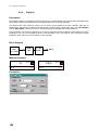
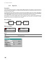
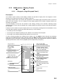
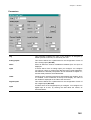
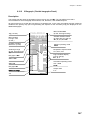
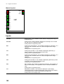
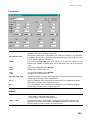
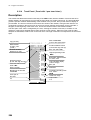
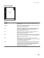
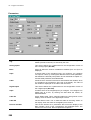
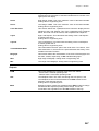
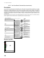
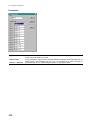
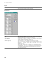
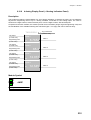
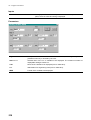
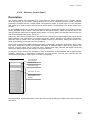
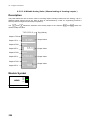
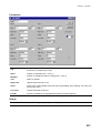
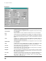
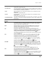
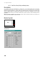
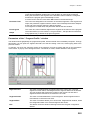
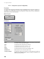
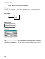
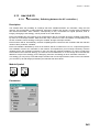
Chapter 9. – Modules
TAG
This parameter indicates the name of the instance, as assigned by
default (module mnemonic) or entered by the user.
Points
In this section you describe the shape of the characteriser, by entering,
one at a time, the data of the breakpoints. The maximum number of
points is 12.
A breakpoint is defined by specifying the IN and OUT coordinate
values.
Format
The field specifies the number of digits (mask) and the digital point
position, that all the breakpoint coordinates must have.
To avoid loss of precision, or this selection must be in line with the
number of digits of the IN signal.
Y-Value
Value of the coordinate OUT for a breakpoint of the characteriser, in
engineering units.
X-Value
Value of the coordinate IN for a breakpoint of the characteriser, in
engineering units.
Operating Notes
To operate correctly, carry on the following steps:
1) Set the proper Format, by selecting the mask setting you prefer.
2) Enter the number of breakpoints the characteriser profile consists of. Automatically in the bottom part of
the window, a table, with all the breakpoints, is shown.
3) Click on the coordinate location of the breakpoint, you want to modify, and enter the new values. Repeat
this operation for all the breakpoint you have to set or modify.
Output
OUT
Characteriser Output with the value of the characteriser profile function
F, corresponding to the value of the input IN
Analog value in engineering units.
137