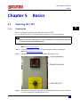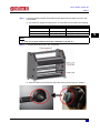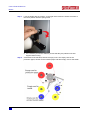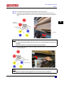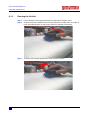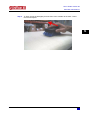
1
User’s Guide User’s Guide Unifixer 65 Copyright notice COPYRIGHT © 1/4/10 Mutoh Europe nv All rights reserved. Mutoh Europe nv reserves the right to modify the information contained in this manual at any time without prior notice. This document may not be reproduced by any means, in whole or in part, without written permission of the copyright owner. Mutoh furnished this document to support the Unifixer 65. In consideration of the furnishing of the information contained in this document, the party to whom it is given, assumes its custody and control and agrees to the following: The information herein contained is given in confidence, and any part thereof shall not be copied or reproduced without written consent of Mutoh Europe nv This document or the contents herein under no circumstances shall be used in the manufacture or reproduction of the article shown and the delivery of this document shall not constitute any right or license to do so. 1 April 2010 Published: Mutoh Europe nv, Archimedesstraat 13, B-8400 Oostende, BELGIUM www.mutoh.eu AP-75393 - Revision 1.1 3 User’s Guide Unifixer 65 IMPORTANT NOTICE Trademarks mentioned in this guide Mutoh, Unifixer 65 are registered trademarks or product names of Mutoh Europe nv. Windows95, Windows98, Windows NT4.0, Windows2000, Windows XP, and MS-DOS are registered trademarks or product names of Microsoft Corporation. Other company and product names may be registered trademarks or product names. Note 4 The product and the contents of this publication may be changed without prior notification. Mutoh Europe nv has made the best efforts to keep this publication free from errors, but if you find any uncertainties or misprints, please contact the reseller from which you bought this equipment or email us: [email protected]. Mutoh Europe nv shall not be liable for any damages or troubles resulting from the use of this equipment or this guide. AP-75393 - Revision 1.1 User’s Guide Unifixer 65 Table of contents Chapter 1 Safety instructions . . . . . . . . . . . . . . . . . . . . . . . . . . . 7 1.1 Compliance with the following regulations . . . . . . . . . . . . . . . 7 1.2 Managing fumes and vapours . . . . . . . . . . . . . . . . . . . . . . . . . . 8 1.3 Warnings, cautions and notes . . . . . . . . . . . . . . . . . . . . . . . . . . 8 1.4 Safety instructions . . . . . . . . . . . . . . . . . . . . . . . . . . . . . . . . . . . 9 Safety mechanisms. . . . . . . . . . . . . . . . . . . . . . . . . . . . . . . . . . . . . . . 11 1.5 Safety labels . . . . . . . . . . . . . . . . . . . . . . . . . . . . . . . . . . . . . . . 12 Chapter 2 Unpacking the machine . . . . . . . . . . . . . . . . . . . . . . 13 2.1 In-the-box contents. . . . . . . . . . . . . . . . . . . . . . . . . . . . . . . . . . 13 2.2 Unpacking procedure . . . . . . . . . . . . . . . . . . . . . . . . . . . . . . . . 14 Chapter 3 Installing the Unifixer 65 . . . . . . . . . . . . . . . . . . . . . 19 3.1 Introduction . . . . . . . . . . . . . . . . . . . . . . . . . . . . . . . . . . . . . . . . 19 Installation environment requirements . . . . . . . . . . . . . . . . . . . . . . . 19 3.2 Securing the Unifixer 65 in its end location . . . . . . . . . . . . . . 20 3.3 Installing the feeding tray. . . . . . . . . . . . . . . . . . . . . . . . . . . . . 21 3.4 Installing the heating element . . . . . . . . . . . . . . . . . . . . . . . . . 23 3.5 Connecting an air filter . . . . . . . . . . . . . . . . . . . . . . . . . . . . . . . 29 Chapter 4 Product overview . . . . . . . . . . . . . . . . . . . . . . . . . . . 31 4.1 Front view . . . . . . . . . . . . . . . . . . . . . . . . . . . . . . . . . . . . . . . . . 31 4.2 Rear view . . . . . . . . . . . . . . . . . . . . . . . . . . . . . . . . . . . . . . . . . . 33 AP-75393 - Revision 1.1 - 1/4/10 5 User’s Guide Unifixer 65 4.3 Operation panel. . . . . . . . . . . . . . . . . . . . . . . . . . . . . . . . . . . . . 34 4.4 Overview technical specifications. . . . . . . . . . . . . . . . . . . . . . 36 Overview recommended exposure time . . . . . . . . . . . . . . . . . . . . . 36 Chapter 5 Basics . . . . . . . . . . . . . . . . . . . . . . . . . . . . . . . . . . . . 37 5.1 Powering ON / OFF . . . . . . . . . . . . . . . . . . . . . . . . . . . . . . . . . . 37 5.2 Powering ON . . . . . . . . . . . . . . . . . . . . . . . . . . . . . . . . . . . . . . . . . . . . 37 Powering OFF . . . . . . . . . . . . . . . . . . . . . . . . . . . . . . . . . . . . . . . . . . . 38 Emergency stop . . . . . . . . . . . . . . . . . . . . . . . . . . . . . . . . . . . . 39 5.3 5.4 5.5 Emergency reset . . . . . . . . . . . . . . . . . . . . . . . . . . . . . . . . . . . . . . . . . 39 Loading media. . . . . . . . . . . . . . . . . . . . . . . . . . . . . . . . . . . . . . 40 Loading media for transfer paper printing . . . . . . . . . . . . . . . . . . . . 40 Loading media for fixing direct printed fabric . . . . . . . . . . . . . . . . . 50 Adjustments and recommendation . . . . . . . . . . . . . . . . . . . . . 59 Temperature adjustment . . . . . . . . . . . . . . . . . . . . . . . . . . . . . . . . . . 59 Speed adjustment . . . . . . . . . . . . . . . . . . . . . . . . . . . . . . . . . . . . . . . . 60 Media tension adjustment . . . . . . . . . . . . . . . . . . . . . . . . . . . . . . . . . 60 Transportation. . . . . . . . . . . . . . . . . . . . . . . . . . . . . . . . . . . . . . 61 Short distance transportation . . . . . . . . . . . . . . . . . . . . . . . . . . . . . . 61 Long distance transportation . . . . . . . . . . . . . . . . . . . . . . . . . . . . . . . 61 Chapter 6 Periodical maintenance . . . . . . . . . . . . . . . . . . . . . . 63 6.1 Done by the end user.. . . . . . . . . . . . . . . . . . . . . . . . . . . . . . . . 63 Cleaning the felt belt . . . . . . . . . . . . . . . . . . . . . . . . . . . . . . . . . . . . . . 64 AP-75393 - Revision 1.1 - 1/4/10 6 User’s Guide Unifixer 65 Safety instructions Chapter 1 Safety instructions This chapter explains the installation of Unifixer 65, warning terms that operators need to know, caution items and warning labels on the main unit. 1 Important 1.1 When installing and operating the Unifixer 65, be sure to follow the directions and warnings in this guide. Compliance with the following regulations The CE marking is a mandatory European marking for certain product groups to indicate conformity with the essential health and safety requirements set out in European Directives. By affixing the CE marking, the manufacturer, his authorized representative, or the person placing the product on the market or putting it into service ensures that the item meets all the essential requirements of all applicable EU directives and that the applicable conformity assessment procedures have been applied. Your product is designed and manufactured with high-quality materials and components, which can be recycled and reused. When this crossed-out wheeled bin submenu is attached to a product, it means the product is covered by the European Directive 2002/96/EC - WEEE regulation. Please inform yourself about the local separate collection system for electrical and electronic products. Please act according to local rules and do not dispose of your old products with your normal household waste. The correct disposal of your old product will help prevent potential negative consequences for the environment and human health. AP-75393 - Revision 1.1 7 User’s Guide Unifixer 65 Safety instructions 1.2 1.3 Managing fumes and vapours When the unit is used for transferring from paper to fabric, no fumes or vapours need to be taken care of. During the fixation process of directly printed fabrics however, depending on the ink type and fabric used, hot fumes & vapours may be released. In order to protect human health, these fumes and vapours need to be managed. To do this, an air purification system (APS) needs to be connected. Be aware that the released fumes and vapours will be hot. When cooling down they will condensate. When using a Mutoh APS this condensate will be managed. Regarding the use and maintenance of the proper Mutoh APS, please consult the Mutoh APS user manual. When using a non-Mutoh APS, you will need to make sure that these liquids do not damage your APS. Because of differences in the local regulations and required working conditions, it is wise to consult a local consultancy agency to determine the involved regulations. Warnings, cautions and notes Safety terms in this manual and the contents of warning labels attached to the Unifixer 65 are categorized into the following three types, depending on the degree of risk (or the scale of accident). Read the following explanations carefully and follow the instructions in this manual. Safety terms Important Caution Notes 8 Details Must be followed carefully to avoid death or serious bodily injury. Must be observed to avoid bodily injury (moderate or light) or damage to your equipment. Contains important information and useful tips on the operation of your Unifixer 65. AP-75393 - Revision 1.1 User’s Guide Unifixer 65 Safety instructions 1.4 Safety instructions Machines must be installed according to Mutoh’s installation procedure also after moving machines to another location: maintenance needs to be done according to the service manual. To prevent fire or electrical shock, never use a power supply source other than the one rated for the product in the country where you purchased the product. Use only the provided power cable. To prevent fire or electrical shock, follow the instructions below when handling the power cable: Do not cut or modify the cable. Do not put heavy objects on the cable. Do not bend, twist, knot or pull the cable. Do not wire the cable near equipment that generates heat. Do not use the cable with any other electrical device Do not handle the cable with wet hands Be aware of all caution and warning labels to avoid potentially hazardous situations. To prevent fire or electrical shock, machines must be connected to a properly grounded electrical power outlet. Do not connect the power cable to a power strip or a power source shared by other electrical devices. Make sure that no foreign substances such as dust etc. are stuck to the power plug. Make sure that the power plug is firmly inserted to the edge of the power socket. Do not plug to a multi-socket plug Do not leave the electric lead in contact with a warm surface. Do not use extension cord with a small diameter section not corresponding to the power of the machine To unplug the machine, disconnect the plug without pulling on the supply lead. Do not disable any safety precautions systems. Do not operate the unit unless all parts are mounted. Do not place the machine in the following areas. Doing so may result in the machine tipping or falling over and causing injury. Unstable surfaces Sloping floors Areas subject to vibration by other equipment Do not stand on or place heavy objects on your machine. Doing so may result in the machine tipping or falling over and causing injury. AP-75393 - Revision 1.1 9 1 User’s Guide Unifixer 65 Safety instructions 10 Do not place the machine in humid and dusty areas, close to water or in areas exposed to flammables. Doing so may result in electrical shock or fire. Do not insert or drop metal or inflammable objects into openings, such as ventilation outlets. Doing so may result in electrical shock and fire. Do not touch the media guide during operation. Stop using your machine if a liquid has been spilled into it. This may cause electrical shock or fire. Switch the machine off as soon as possible, unplug the power cord, and contact your local Mutoh dealer. Do not use the machine if the supply lead is damaged. Be sure to power OFF the machine and unplug the power cable from the outlet before cleaning the machine. Use a damp cloth to clean the machine. Do not use thinner, benzene, alcohol or other active agents. Do not tilt the machine, place it against a wall or turn it upside down. Movement after transport is also not covered by the warranty. When cutting roll media, be careful. Incorrect handling can result in injury to the hands and fingers from the razor blade. To prevent back pains and other injuries, always work with at least 2 people to unpack or move the machine. Keep the machine horizontally during transportation. when using the screw jack while unloading the machine, ensure the screw jack is laying well flat on the pallet floor and prevent it from slipping and sliding Do NOT transport the machine to another room without contacting your local Authorized Mutoh Dealer. At least 2 persons are required for installing the feeding tray To install the heating element, it is necessary to open both sides of the machine. This should be done by a skilled and approved technician. While installing the heater element, ensure the machine is not plugged in to the power The machine should be installed in a well-ventilated place. The dye sublimation heat transfer calender works with high temperature. It is recommended not to leave the workshop till it has come down to the ambient temperature In order to preserve the equipment, use only material that are suitable for heat transfer. Adjust the working temperature according to the media you are using. Do not feed material that would not stand excess amount of heat with a risk of burning or melting when exposed to too much heat - i.e. Adhesive tape. AP-75393 - Revision 1.1 User’s Guide Unifixer 65 Safety instructions 1.4.1 Safety mechanisms The Unifixer 65 has got 2 safety mechanisms that would immediately stop the rotation of the heating drum. Plexiglas safety cover: The safety cover must be lowered (=in the working position) in order to start the motor. This safety mechanism has to be kept on the machine in order to protect the user from crushing hands and to prevent undesired object from getting taken into the machine and therefore possible mechanical hazards. 2 emergency stop buttons: easily reachable, one on the front right hand side and one on the rear right hand side. The use of one of these emergency stop buttons would switch off instantly the rotation of the heating drum. Safety reset button Each time one of these safety mechanisms is used, correct the defect, press on the safety reset button (Rep. 8) to reset the system and run the machine normally. Despite the operation safety mechanisms on the machine, highest caution and care have to be made when using or maintaining the machine: Do not put fingers or other body part between the heating drum and the felt belt. Crushing and scald hazards. Tie up long hairs, do not wear tie or wide clothes in order to avoid getting trapped inside the driving mechanism. Risks of strangling, scalds and tearing of hairs. Do not wear jewellery when using the machine. Such object, if fed into the machine may cause damages to the mechanic of the machine. Always unplug the machine from the power plug when maintaining the machine. Electrocution risk. AP-75393 - Revision 1.1 11 1 User’s Guide Unifixer 65 Safety instructions 1.5 Safety labels Be sure to read and understand the safety warnings before handling the printer. A safety label is used on parts of the machine which especially need your attention. Understand the locations and the descriptions of the danger associated with each label before operating the Unifixer 65. Label Description This sign is next to warm surfaces and indicates that there is a burning risks This sign shows the presence of electrical components and indicates that there is an electrocution risks This sign warns about physical injuries and indicates that there is a crushing risks 12 AP-75393 - Revision 1.1 User’s Guide Unifixer 65 Unpacking the machine Chapter 2 2.1 Unpacking the machine 2 In-the-box contents Please read this chapter to know the in-the-box content. N° Description 1 Unifixer 65 2 User’s Guide (this manual) 3 EU power cable fixed on the Unifixer 65 4 Media loading shaft (6 pieces premounted) 5 Screw jack 6 Quartz glass heating element (packed separately) 7 Wooden ramp AP-75393 - Revision 1.1 13 User’s Guide Unifixer 65 Unpacking the machine 2.2 Unpacking procedure Please read this chapter thoroughly to unpack the Unifixer 65 correctly. 14 Step 1: Remove the lid on top of the cardboard case. Step 2: Tear off the cardboard end and remove it. Step 3: Screw the 3 brake handles provided on the left of the machine. Unlock both lower shaft locking system and unload the shafts from the machine. AP-75393 - Revision 1.1 User’s Guide Unifixer 65 Unpacking the machine Step 4: A wooden ramp is provided for easy unloading of the machine. Take it out of the crate, going through the two lower tension bars. Position the ramp edge to edge with the pallet. 2 Step 5: The machine is fixed to the pallet with 2 metal brackets. These brackets are screwed to the pallet. Unscrew the 4 nuts with a 17mm key and an 8 mm hexagon key. Remove each locking screws. AP-75393 - Revision 1.1 15 User’s Guide Unifixer 65 Unpacking the machine Step 6: To remove the brackets, turn them horizontally to the top of the machine and slide them toward the centre of the machine. Take them out of the machine from the front. Step 7: The machine is resting on 4 wooden blocks (2 on each end). To unload the machine, these blocks have to be removed, using the screw jack provided. Position the screw jack in the middle of the castors, on the side where you have installed the ramp. Lift up the machine so that you have enough space to remove the 2 wooden blocks on this side by sliding them out. Lift the machine down from this side and repeat at the other side of the machine. Caution 16 Ensure that the screw jack is lying well flat on the pallet floor and prevent it from slipping and sliding. AP-75393 - Revision 1.1 User’s Guide Unifixer 65 Unpacking the machine Roll the machine slowly down to the floor on the ramp. Step 8: Two persons are required to guide and keep the machine straight. Caution Maintain and guide firmly the machine while unloading 2 Step 9: Finally, place the machine at the required location in your premises, considering the remarks in Securing the Unifixer 65 in its end location on page 20. AP-75393 - Revision 1.1 17 User’s Guide Unifixer 65 Unpacking the machine 18 AP-75393 - Revision 1.1 User’s Guide Unifixer 65 Installing the Unifixer 65 Chapter 3 3.1 Installing the Unifixer 65 3 Introduction It is very important that the installation environment fulfils following conditions to obtain good quality: 3.1.1 Install the Unifixer 65 on a flat floor, next to an easily accessible plug. Do not touch the socket with damp hands. The machine should be installed in a well-ventilated place. Installation environment requirements Choose a place for installation following the requirements in the table below. Dimensions W x H x D 208 x 155 x 96 cm AP-75393 - Revision 1.1 Net weight 480 kg Voltage 230 V / 50 - 60 Hz (single phase) Frequency 50-60Hz Current 28 A 19 User’s Guide Unifixer 65 Installing the Unifixer 65 3.2 Securing the Unifixer 65 in its end location The machine is delivered with 4 stabilising feet to be installed on the machine, once the machine is on the floor. To install these feet, make sure the lockable castors are locked first. Step 1: Lift up the machine with the screw jack on one end, and screw the stabilising feet in. Step 2: Do the same on the other end. The stabilising feet enable you to adjust the level of the machine. To do so, adjust the height of each foot with a flat 17mm nut key. Each foot has got a counter locking nut to screw back after adjustment in order to lock the position. Note 20 It is highly recommended to use these stabilising feet to ease the strength on the castors, especially when loading heavy material reels. AP-75393 - Revision 1.1 User’s Guide Unifixer 65 Installing the Unifixer 65 3.3 Installing the feeding tray Note Step 1: 2 persons are required to install the feeding tray. Loosen the screw (one on each side) while the other person keeps the table high. 3 Note Make sure that the insulation strips remain between the feeding tray and the body of the machine. AP-75393 - Revision 1.1 21 User’s Guide Unifixer 65 Installing the Unifixer 65 Step 2: Lower the table and screw the 2 screws in the working position. Note 22 Do not loosen the screws closer to the felt belt! AP-75393 - Revision 1.1 User’s Guide Unifixer 65 Installing the Unifixer 65 3.4 Installing the heating element To install the heating element, it is necessary to open both sides of the machine. This should be done by a skilled and approved technician. Step 1: Place back all self locking shaft on the machine and unscrew totally the 3 braking handles. AP-75393 - Revision 1.1 23 3 User’s Guide Unifixer 65 Installing the Unifixer 65 Unscrew the metal side panels with a Torx T20 screwdriver. Step 2: Caution Make sure the machine is powered OFF. Note Step 3: 24 For each metal side panel, start by unscrewing the screws at the bottom. Be careful when unscrewing the top screws, the metal side panel is heavy. Unscrew the heating element holder on both sides with an 8 mm nut key. AP-75393 - Revision 1.1 User’s Guide Unifixer 65 Installing the Unifixer 65 Insert the quartz heating element in the heating drum. Step 4: Align the heating element connectors straight with the glass. Caution Handle the heating element with highest care. Note Perform following steps with 2 persons. Person 1 inserts the lamp while person 2 helps taking the lamp out at the other side. To make the insertion of the heating element through the heating drum easier, align your eye with the glass tube and the light from the opposite drum hole. Step 5: In case the connector ends bend, it will become difficult to take it out from the other end. In this case, take the heating element back out, align the connector straight again and restart. Once the quartz heating element is inserted, let a similar length of connector out of the heating drum on each side. AP-75393 - Revision 1.1 25 3 User’s Guide Unifixer 65 Installing the Unifixer 65 26 Step 6: Put the quartz holder back in position on each end, including the quartz centring part to the quartz holder. Step 7: Screw the left quartz holder and connect the quartz heating element to the connector. AP-75393 - Revision 1.1 User’s Guide Unifixer 65 Installing the Unifixer 65 Step 8: Screw the right quartz holder and connect the quartz heating element to the safety thermostat connector. 3 Note After installing the left and right bracket, verify that the quartz centring part is still positioned correctly. An incorrect positioned bracket could lead to a malfunctioning machine. AP-75393 - Revision 1.1 27 User’s Guide Unifixer 65 Installing the Unifixer 65 Step 9: 28 Take the metal side panels back in place and screw all screws back in with a Torx T20 screwdriver starting from the top. Screw the 3 bracking handles back in position. AP-75393 - Revision 1.1 User’s Guide Unifixer 65 Installing the Unifixer 65 3.5 Connecting an air filter When the unit is used for transferring from paper to fabric, no fumes or vapours need to be taken care of. During the fixation process of directly printed fabrics however, depending on the ink type and fabric used, hot fumes & vapours may be released. In order to protect human health, these fumes and vapours need to be managed. To do this, an air purification system (APS) needs to be connected. Be aware that the released fumes and vapours will be hot. When cooling down they will condensate. When using a Mutoh APS this condensate will be managed. Regarding the use and maintenance of the proper Mutoh APS, please consult the Mutoh APS user manual. When using a non-Mutoh APS, you will need to make sure that these liquids do not damage your APS. Because of differences in the local regulations and required working conditions, it is wise to consult a local consultancy agency to determine the involved regulations. AP-75393 - Revision 1.1 29 3 User’s Guide Unifixer 65 Installing the Unifixer 65 30 AP-75393 - Revision 1.1 User’s Guide Unifixer 65 Product overview Chapter 4 4.1 Product overview Front view 4 N° AP-75393 - Revision 1.1 Description 1 P-Stabilising feet 2 Lockable castors 3 Loading of the lower reel 4 Lower and middle shaft locking systems 5 Loading of the central reel 6 Lower and middle shaft locking systems 7 Feeding table 8 Belt guide 9 Working parameter control board 10 Emergency stops 31 User’s Guide Unifixer 65 Product overview N° 32 Description 11 Self locking shaft guide 12 Loading of the upper reel 13 Plexiglas safety cover AP-75393 - Revision 1.1 User’s Guide Unifixer 65 Product overview 4.2 Rear view 4 N° AP-75393 - Revision 1.1 Description 1 Exhaust fumes extraction holes 2 Fuse holder 3 Main switch 4 Felt belt 5 Reel self locking shaft 6 Emergency stops 7 Tension adjustment handle for the upper feeding shaft 8 Tension adjustment handle for the middle feeding shaft 9 Tension adjustment handle for the lower feeding shaft 10 Media exit guide 11 Power cord 12 Take up of the lower reel 13 Take up of the central reel 14 Take up of the upper reel 33 User’s Guide Unifixer 65 Product overview 4.3 Operation panel N° Description 34 1 Temperature control 2 PV: Display of the actual drum temperature given by the infra red sensor 3 SV: Working set temperature 4 Increase working temperature 5 Lower working temperature 6 Temperature unit AP-75393 - Revision 1.1 User’s Guide Unifixer 65 Product overview N° Description 7 Heat exposure contact time (seconds) (speed adjustment) 8 Forward 9 Stop 10 Reverse 4 11 Safety reset 12 Emergency stop 13 Heating signal AP-75393 - Revision 1.1 35 User’s Guide Unifixer 65 Product overview 4.4 4.4.1 Overview technical specifications Maximum working width 1700 mm (67'') Maximum temperature 220°C - 428°F Diameter of the heating drum 250 mm (10'') Type heater Quartz Infra red Belt material Nomex Recommended Working speed / Exposure time Min: 17 m/h / 90 s Max: 65 m/h / 40s Dimensions W x H x D 208 cm x 155 cm x 96 cm 81'' x 61'' x 38'' Net weight 480 Kg - 1058 lbs Voltage 230 - 240 V (Single phase) Frequency 50Hz - 60Hz Current 28 A Overview recommended exposure time Exposure time Transfer capacity (m / min) / (Yard / min) Transfer capacity (m / h) / (Yard / h) 20 1.40 / 1.53 83.8 / 91.8 25 1.32 / 1.44 79.0 / 86.4 30 1.24 / 1.36 74.2 / 81.6 35 1.16 / 1.27 69.5 / 76.2 40 1.10 / 1.20 64.7 / 72.0 45 1.00 / 1.10 59.9 / 66.0 50 0.92 / 1.01 55.1 / 60.6 55 0.84 / 0.92 50.3 / 55.2 60 0.76 / 0.83 45.5 / 49.8 65 0.68 / 0.74 40.7 / 44.4 70 0.60 / 0.66 35.9 / 39.6 75 0.52 / 0.57 31.1 / 34.2 80 0.44 / 0.48 26.3 / 28.8 85 0.36 / 0.39 21.5 / 23.4 90 0.28 / 0.31 16.7 / 18.6 The grey values correspond to the recommended exposure time for good transfer results. 36 AP-75393 - Revision 1.1 User’s Guide Unifixer 65 Basics Chapter 5 Basics 5.1 Powering ON / OFF 5.1.1 Powering ON 5 When connecting the machine to the power grid, make sure that: Your machine’s tension corresponds with the tension of you electrical network. Note Step 1: Refer to the local regulations for more information concerning the electrical connection norm and compatible plug. Switch on the power switch located at the back of the machine. Refer to Rear view on page 33 Step 2: Press the reset button in order to activate all machine safety mechanisms. Refer to Operation panel on page 34 Step 3: Set the temperature (215°C recommended) and speed to slow. Step 4: Wait until the Unifixer 65 reaches the requested temperature (215°C) before starting to use the Unifixer 65. This takes about 35 min. AP-75393 - Revision 1.1 37 User’s Guide Unifixer 65 Basics 5.1.2 Powering OFF Step 1: Set the heater temperature as low as possible. Refer to Operation panel on page 34 Step 2: Increase the rotation speed of the felt belt to the maximum and let the machine cool down for 10 minutes. Step 3: Switch off the power switch located at the back of the machine. Note Make sure no objects such as protection paper, transfer paper or fabrics are on or near the Unifixer 65. Due to static electricity, it might happen that the protection paper, transfer paper or fabric is being pulled into the machine again. Note 38 The machine may be switched off while the temperature is still hot, but this is not recommended. AP-75393 - Revision 1.1 User’s Guide Unifixer 65 Basics 5.2 Emergency stop Important If a situation requires an immediate shutdown of all activities push the emergency without hesitation. If using the emergency break, make sure to remove all materials such as protection paper, transfer paper and fabric as soon as possible. The Unifixer 65 has 2 emergency stops that immediately stop the rotation of the heating drum. They are easily reachable, one on the front right hand side and one on the rear right hand side. A third emergency break is the front cover. In case of opening the cover, all mechanical processes will stop immediately. Be aware that opening the front cover will not stop the heaters. 5.2.1 Emergency reset Important Before resetting the emergency brake, make sure solve the situation that caused the emergency shutdown. To run the machine, the emergency stop must be released and the user protection cover must be in working position. Once done, press on the reset button to reset the safety mechanisms. Refer to Operation panel on page 34 When switching the machine on with the main switch, press the safety reset button to activate the machine. AP-75393 - Revision 1.1 39 5 User’s Guide Unifixer 65 Basics 5.3 Loading media 5.3.1 Loading media for transfer paper printing In order to preserve the equipment, use only material that are suitable for heat transfer. Adjust the working temperature according to the media you are using. Do not feed material that does not stand excess amount of heat with a risk of burning or melting when exposed to too much heat. Note When loading protection paper, fabric or transfer paper, make sure no tape remains on them. Due to the temperature the tape might melt and ruin your print and even the felt belt. The following is a technical drawing of how to load your media. The arrows next to the print roll indicate the printed side. The arrows next to the textile roll indicate the side on which you want the print to be transferred. 40 AP-75393 - Revision 1.1 User’s Guide Unifixer 65 Basics Step 1: Load the protection paper, the printed transfer paper and the fabric roll onto a self locking shaft. The maximum weight and dimensions of media that can be loaded are following: Media Max diameter Max weight Protection paper 250 mm (9.84 “) 100 kg (220 lbs) Printed transfer paper 250 mm (9.84”) 100 kg (220 lbs) Textile 250 mm (9.84”) 100 kg (220 lbs) 5 Note Step 2: The core of your media should have a diameter of 76 mm (3”). Load the self-locking core in the Unifixer 65. AP-75393 - Revision 1.1 Push the shaft in its left support and twist it a bit so that it locks it in position. 41 User’s Guide Unifixer 65 Basics Step 3: Lock the shafts with the lockers, on the right of the machine. Secure the locker in the lower position with the spring screw. Step 4: 42 It is necessary to lock the shafts to prevent that they are pulled out of their support while running. At the back of the machine, foresee 3 empty cores. One empty core for the protection paper, another for the transfer paper and third empty core for the textile. AP-75393 - Revision 1.1 User’s Guide Unifixer 65 Basics Step 5: Cut the front of the protection paper in a V-shape. Step 6: Open the front cover. Step 7: Position the protection paper correctly on the shaft. 5 Note Before loading the protection paper into the Unifixer 65, verify that the protection paper is larger than the printed transfer paper. This to protect the felt belt. AP-75393 - Revision 1.1 43 User’s Guide Unifixer 65 Basics Step 8: Carefully insert the protection paper with your hands as deep as possible. Note Be careful not to crush your fingers when performing this action. Make sure that the protection cover is open when doing this. Never load the protection paper over the protection cover, this will result in damage to protection cover and possibly to the Unifixer 65. Step 9: 44 Close the cover and push the reset button. AP-75393 - Revision 1.1 User’s Guide Unifixer 65 Basics Step 10: Push the start button, the felt belt will grab the protection paper. Step 11: At the back of the Unifixer 65, grab the out-coming protection paper and move it under the tension bar and over the swing arms to the protection paper take up and fix it. 5 Note In case the protection paper tears apart when it is already loaded, the tension is too high. Lower the tension on the protection paper with the brakes. Step 12: In front of the Unifixer 65, take the transfer paper and move it over the tension bar onto the platform. Note Make sure that the speed adjustment is set to the working conditions. AP-75393 - Revision 1.1 45 User’s Guide Unifixer 65 Basics Step 13: Place the transfer paper flat on the table with equal tension to the left and right side. Step 14: Carefully insert the transfer paper until it is being grabbed by the belt and protection paper. Note 46 Make sure that the printed side of the transfer paper is facing up. AP-75393 - Revision 1.1 User’s Guide Unifixer 65 Basics Step 15: Once the transfer paper is moving, place the fabric onto the transfer paper with equal tension left and right. By slightly pushing down the fabric, the transfer paper will guide the fabric into the Unifixer 65. 5 Note Make sure that the side of the fabric you want to print is facing down onto the transfer paper. Step 16: At the back of the Unifixer 65, the transfer paper will come seconds earlier then the fabric. It is essential that both the transfer paper and fabric are loaded correctly for optimum output quality. AP-75393 - Revision 1.1 47 User’s Guide Unifixer 65 Basics Transfer paper 48 load the transfer paper behind the first tensioning swingbar, over the second one. Afterwards, lead the transfer paper behind the tensioning bar and fix the transfer paper to the empty core. AP-75393 - Revision 1.1 User’s Guide Unifixer 65 Basics Fabric load the fabric before the first tensioning swingbar, over the second one. Afterwards, fix the fabric to the empty core. 5 AP-75393 - Revision 1.1 49 User’s Guide Unifixer 65 Basics 5.3.2 Loading media for fixing direct printed fabric The following is a technical drawing of how to load your media. The arrows next to the textile roll indicate the side on which you want the print to be transferred. 50 AP-75393 - Revision 1.1 User’s Guide Unifixer 65 Basics Step 1: Load the 2 rolls of protection paper, and the printed fabric roll onto a self locking shaft. The maximum weight and dimensions of media that can be loaded is as follows: Media Max diameter Max weight Protection paper 250 mm (9.84 “) 100 kg (220 lbs) Printed textile 250 mm (9.84”) 100 kg (220 lbs) 5 Note Step 2: The core of your media should have a diameter of 76 mm (3”). Load the self-locking core in the Unifixer 65. AP-75393 - Revision 1.1 Push the shaft in its left support and twist it a bit so that it locks it in position. 51 User’s Guide Unifixer 65 Basics Step 3: Lock the shafts with the lockers, on the right of the machine. Secure the locker in the lower position with the spring screw. It is necessary to lock the shafts to prevent that they are pulled out of their support while running. Step 4: Cut the front of the protection paper in a V-shape. Step 5: Open the front cover. Step 6: Position the protection paper correctly on the shaft. Note 52 Before loading the protection paper into the Unifixer 65, verify that the protection paper is larger than the printed transfer paper. This to protect the felt belt. AP-75393 - Revision 1.1 User’s Guide Unifixer 65 Basics Step 7: Carefully insert the protection paper with your hands as deep as possible. 5 Note Be careful not to crush your fingers when doing this. Make sure that the protection cover is open when doing this. Never ever load the protection paper over the protection cover, this will result in damage to protection cover and possibly to the Unifixer 65. AP-75393 - Revision 1.1 53 User’s Guide Unifixer 65 Basics Step 8: Close the cover and push the reset button. Step 9: Push the start button, the felt belt will grab the protection paper. Step 10: At the back of the Unifixer 65, grab the out-coming protection paper and move it under the 2 tension bars to the protection paper take up and fix it. Note 54 In case the protection paper tears apart when it is already loaded, the tension is too high. Lower the tension on the protection paper with the brakes. AP-75393 - Revision 1.1 User’s Guide Unifixer 65 Basics Step 11: In front of the Unifixer 65, cut the front of the second roll of protection paper in a V-shape. 5 AP-75393 - Revision 1.1 55 User’s Guide Unifixer 65 Basics Step 12: Load the second layer of protection paper over the tension bar onto the platform. 56 AP-75393 - Revision 1.1 User’s Guide Unifixer 65 Basics Step 13: Carefully insert the protection paper until it is being grabbed. 5 Note Make sure that the speed adjustment is set to the working conditions. Step 14: At the back of the machine, grab the protection paper, and load it to the empty core. AP-75393 - Revision 1.1 57 User’s Guide Unifixer 65 Basics Step 15: Once both protection papers are loaded, place the fabric onto the protection paper with equal tension left and right. By slightly pushing down the protection paper will guide the fabric into the Unifixer 65. Note Make sure that the side of the fabric you want to print is facing up. Step 16: On the back of the Unifixer 65, lead the fabric in front of the first tension swing arm directly to the empty core on the middle shaft. 58 AP-75393 - Revision 1.1 User’s Guide Unifixer 65 Basics 5.4 Adjustments and recommendation 5.4.1 Temperature adjustment The heating of the heating drum will start if the set temperature is above the actual read temperature. 5 Note The infra red sensor measuring the heat on the heating drum is adjusted and precise for temperature ranging from 160°C (320°F) to 220°C (428°F), corresponding to the current working temperature area. Out of this range, the accuracy of the measured heat on the display may not be right. Adjust the heating drum temperature by pressing the temperature adjustment keys. Refer to Operation panel on page 34 To preserve the machine and avoid any damage on the felt belt, the maximum set temperature is limited at 220°C (428°F). Recommended working temperature: 215°C (419°F). It is important to adapt the speed adjustment (heat exposure contact time) in accordance with the machine features. If temperature decreases too much while transferring, increase the working temperature or the heat exposure contact time. The right combination of speed and heat on the machine will enable you to reach your expected quality level. It is recommended to increase the set temperature by 10-15°C above the working temperature in order to compensate possible loss of heat caused by thermal exchanges between the media and the heating drum. While heating up the machine, let the drum spin at the "SLOW" speed. This heating speed will provide a homogeneous spread of the temperature in the heating drum and will help to reach the set working temperature faster. AP-75393 - Revision 1.1 59 User’s Guide Unifixer 65 Basics 5.4.2 Speed adjustment The speed is adjusted with the speed adjustment button. Refer to Operation panel on page 34 The recommended working speed, depending on the transfer paper and fabric, is between 90 and 45 seconds. Forward To start the motor, press the forward button. The motor starts automatically. Refer to Operation panel on page 34 Stop To stop the motor, press the stop button. Refer to Operation panel on page 34 Backwards This button has to be kept pressed in order to keep driving reverse motion. The reverse speed is adjusted with the speed adjustment button as for the forward mode. Refer to Operation panel on page 34 5.4.3 Media tension adjustment The brake handles enable to adjust the tension of the media. Adjusting the tension can be necessary in case you notice unequal tension on your media. To increase the tension, turn the brake handle clockwise (+). To release the tension, turn it counter clockwise (-). Refer to Rear view on page 33 Note 60 Always set the brakes so that the media is slightly tensioned. AP-75393 - Revision 1.1 User’s Guide Unifixer 65 Basics 5.5 Transportation 5.5.1 Short distance transportation For short distances (moving to another room, etc) there are no special requirements. Just make sure that: there are no rough transitions for example at the doorstep. Otherwise several items such as the lamp could get damaged. In case of rough transitions, refer to Long distance transportation on page 61. all shafts are safely secured, if necessary with some extra tape or wire. all support feet are completely turned in to avoid breaking them during transportation. Note 5.5.2 When reinstalling the Unifixer 65 after transportation, condense could occur. Remove this condense with a dry cloth. Long distance transportation In case of moving the Unifixer 65 over a longer distance, for example to another building or to an exhibition, there are several topics that you need to keep in mind. Make sure: all media is removed from the shafts. all shafts are safely secured, if necessary with some extra tape or wire. the quartz glass heating element is removed from the Unifixer 65. In case of removal, follow the procedure in Installing the heating element on page 23 in reverse order. all support feet are completely turned in to avoid breaking them during transportation. the Unifixer 65 is safely secured on a pallet and protected in a crate like when it first arrived. Note In case of rough transitions, make use of the wooden ramp. Note When reinstalling the Unifixer 65 after transportation, condense could occur. Remove this condense with a dry cloth. AP-75393 - Revision 1.1 61 5 User’s Guide Unifixer 65 Basics 62 AP-75393 - Revision 1.1 User’s Guide Unifixer 65 Periodical maintenance Chapter 6 Periodical maintenance 6 This chapter describes the periodical services required on a Unifixer 65. The periodical services ensure a stable quality of the machine. In the periodical services, some parts need to be checked, cleaned or replaced by the end user or by an authorized Mutoh technician 6.1 Done by the end user. Note Please use Original Mutoh spare parts. Any problems caused by use of non-original Mutoh spare parts or other consumables will not be covered by the warranty. Frequency Component Action Immediately Ink waste on the felt belt Let the machine run at working temperature until the remaining ink disappears on the felt belt Felt belt Gently wash with water and soap Make sure it is completely dry before using again. Cleaning the felt belt on page 64 Feeding table Gently wash with water and soap Make sure it is completely dry before using again. Tension bars Gently wash with water and soap Make sure it is completely dry before using again. Metal body Gently wash with water and soap Weekly AP-75393 - Revision 1.1 63 User’s Guide Unifixer 65 Periodical maintenance 6.1.1 64 Cleaning the felt belt Step 1: Let the felt belt running (speed between 90” and slow) at roughly 180°C. Step 2: Brush the belt with a textile brush previously soaked in a soapy water mix. Begin to brush the belt like shown on the picture (from front calender to the back). Step 3: To preserve the felt belt appearance brush the belt clockwise. AP-75393 - Revision 1.1 User’s Guide Unifixer 65 Periodical maintenance Step 4: To finish, brush the belt lightly from the front of the calender to the back. This to remove felt surplus. 6 AP-75393 - Revision 1.1 65 User’s Guide Unifixer 65 Periodical maintenance 66 AP-75393 - Revision 1.1