1
1.0 DESCRIPTION
3.0 INSTALLATION
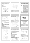
The DM3600 is a highly accurate and stable digital process indicator that accepts all commonly used process
signals. The unit can be used "stand alone" or with the Modbus serial communications option, as part of a
larger system. The case design enables Option Pods to be easily installed without the need for dismantling
or re-calibration. A range of Pods are available for:
Relay outputs
Isolated (4 to 20) mA re-transmission
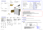
FRONT PANEL
SEALED
TO IP66
BRIGHT SIX
DIGIT
DISPLAY
DISCRETE LED
ALARM
INDICATORS
CYCLE
KEY
SHIFT
KEY
INCREMENT
KEY
WARNING !
INSTALLER - This section must be used by competent personnel only. If this equipment is not installed
in accordance with these instructions, protection against electrical hazards may be impaired. It is the
responsibility of the person installing this equipment to implement this procedure in accordance with the
relevant code of practice (for the installation of instrumentation used in process control systems), issued
by a recognised local body.
MOUNTING - This equipment is classed as PERMANENTLY CONNECTED EQUIPMENT. Hazardous voltages
may be present on the terminals of this equipment. The equipment must be panel mounted into a suitable
enclosure which provides at least IP20 protection behind the panel.
SUPPLY - The supply terminals and associated internal circuitry are isolated from all other parts of the
equipment in accordance with BS EN61010-1, for connection to an installation over-voltage Category II
supply, (pollution degree 2). The supply voltage and frequency must remain within the limits stated on the
product label. The mains supply to the unit must be protected by an external 1 A fuse and a suitable switch
or circuit breaker must be located close to the equipment, in order to isolate the supply.
SIGNAL INPUT/OUTPUTS - All signal input, and communication terminals and associated internal circuitry
are intended for operation at voltages less than 40 VDC. These circuits, which may become accessible
during NORMAL OPERATION, must ONLY be connected to signals complying with the requirements for Safety
Extra Low Voltage (SELV) circuits.
1A 1B 2A 2B
°C
(Read the following safety information before installation)
Tag No.
RELAYS - The relay terminals and associated internal circuitry are isolated from all other parts of the
equipment in accordance with BS EN 61010-1, for connection to an installation over-voltage Category II supply,
(pollution degree 2). The relay operating voltage and current must remain within the limits stated. (Refer
to Section 7.0).
LEGEND
WINDOW
SERVICE - This equipment contains no user serviceable parts and must be returned to supplier for repair.
OPTION
POD SLOT 1
OPTION POD
SLOT 2
(NOT SHOWN)
3.1 INSTALLING INTO A PANEL
The maximum panel thickness is 10 mm. The instrument case has an integral gasket which forms a seal
when the instrument is tightened against the panel. The panel should be clean, smooth and at least 1.6 mm
thick for the seal to be effective.
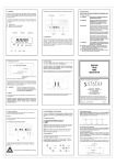
PROCESS
INPUTS
RJ45 COMMS
+ DIGITALS
POWER
CONNECTOR
The diagram below shows the rear panel positions for all electrical connections.
2.0 UNPACKING
WARNING
Use only the retaining screws provided to clamp the instrument to the panel (screws
must be tightened sufficiently to effect a seal but must never be over tightened).
3.2 WIRING
Please inspect the instrument carefully for any signs of shipping damage. The packaging has been designed
to provide maximum protection, however, we cannot guarantee that mishandling will not have damaged
the instrument. In the case of this unlikely event, please contact your supplier immediately and retain the
packaging for subsequent inspection.
Page 1
All connections are made to sockets which are removable for ease of maintenance.
NOTE: CABLE SIZE (0.5 to 1.5) mm²
Page 2